EP2183099B1 - Wall construction and thermal insulation plate - Google Patents
Wall construction and thermal insulation plate Download PDFInfo
- Publication number
- EP2183099B1 EP2183099B1 EP08828126.6A EP08828126A EP2183099B1 EP 2183099 B1 EP2183099 B1 EP 2183099B1 EP 08828126 A EP08828126 A EP 08828126A EP 2183099 B1 EP2183099 B1 EP 2183099B1
- Authority
- EP
- European Patent Office
- Prior art keywords
- capillary
- conductive
- layer
- thermal insulation
- wall construction
- Prior art date
- Legal status (The legal status is an assumption and is not a legal conclusion. Google has not performed a legal analysis and makes no representation as to the accuracy of the status listed.)
- Not-in-force
Links
- 238000009413 insulation Methods 0.000 title claims description 74
- 238000010276 construction Methods 0.000 title claims description 17
- 239000010410 layer Substances 0.000 claims description 119
- 239000000463 material Substances 0.000 claims description 19
- 239000004020 conductor Substances 0.000 claims description 5
- 239000012790 adhesive layer Substances 0.000 claims description 3
- 239000006260 foam Substances 0.000 description 9
- 239000000378 calcium silicate Substances 0.000 description 5
- 229910052918 calcium silicate Inorganic materials 0.000 description 5
- OYACROKNLOSFPA-UHFFFAOYSA-N calcium;dioxido(oxo)silane Chemical compound [Ca+2].[O-][Si]([O-])=O OYACROKNLOSFPA-UHFFFAOYSA-N 0.000 description 5
- 239000004570 mortar (masonry) Substances 0.000 description 5
- 238000009421 internal insulation Methods 0.000 description 4
- 229920005989 resin Polymers 0.000 description 4
- 239000011347 resin Substances 0.000 description 4
- 230000004888 barrier function Effects 0.000 description 3
- 239000011230 binding agent Substances 0.000 description 3
- 230000003139 buffering effect Effects 0.000 description 3
- 238000009422 external insulation Methods 0.000 description 3
- 239000011810 insulating material Substances 0.000 description 3
- 238000004519 manufacturing process Methods 0.000 description 3
- 239000004568 cement Substances 0.000 description 2
- 239000004927 clay Substances 0.000 description 2
- 238000009792 diffusion process Methods 0.000 description 2
- 239000000945 filler Substances 0.000 description 2
- 229910052500 inorganic mineral Inorganic materials 0.000 description 2
- 239000011707 mineral Substances 0.000 description 2
- 239000011490 mineral wool Substances 0.000 description 2
- 239000011505 plaster Substances 0.000 description 2
- 239000004814 polyurethane Substances 0.000 description 2
- 239000000126 substance Substances 0.000 description 2
- NIXOWILDQLNWCW-UHFFFAOYSA-M Acrylate Chemical compound [O-]C(=O)C=C NIXOWILDQLNWCW-UHFFFAOYSA-M 0.000 description 1
- BPQQTUXANYXVAA-UHFFFAOYSA-N Orthosilicate Chemical compound [O-][Si]([O-])([O-])[O-] BPQQTUXANYXVAA-UHFFFAOYSA-N 0.000 description 1
- 229910019142 PO4 Inorganic materials 0.000 description 1
- 239000004698 Polyethylene Substances 0.000 description 1
- 239000004793 Polystyrene Substances 0.000 description 1
- 229920005830 Polyurethane Foam Polymers 0.000 description 1
- 239000002174 Styrene-butadiene Substances 0.000 description 1
- 229920001807 Urea-formaldehyde Polymers 0.000 description 1
- 229920002522 Wood fibre Polymers 0.000 description 1
- 238000010521 absorption reaction Methods 0.000 description 1
- 239000012615 aggregate Substances 0.000 description 1
- GZCGUPFRVQAUEE-SLPGGIOYSA-N aldehydo-D-glucose Chemical compound OC[C@@H](O)[C@@H](O)[C@H](O)[C@@H](O)C=O GZCGUPFRVQAUEE-SLPGGIOYSA-N 0.000 description 1
- PNEYBMLMFCGWSK-UHFFFAOYSA-N aluminium oxide Inorganic materials [O-2].[O-2].[O-2].[Al+3].[Al+3] PNEYBMLMFCGWSK-UHFFFAOYSA-N 0.000 description 1
- 238000009435 building construction Methods 0.000 description 1
- MTAZNLWOLGHBHU-UHFFFAOYSA-N butadiene-styrene rubber Chemical compound C=CC=C.C=CC1=CC=CC=C1 MTAZNLWOLGHBHU-UHFFFAOYSA-N 0.000 description 1
- 239000001913 cellulose Substances 0.000 description 1
- 229920002678 cellulose Polymers 0.000 description 1
- 239000004567 concrete Substances 0.000 description 1
- 239000007799 cork Substances 0.000 description 1
- 230000018044 dehydration Effects 0.000 description 1
- 238000006297 dehydration reaction Methods 0.000 description 1
- 239000006185 dispersion Substances 0.000 description 1
- 230000000694 effects Effects 0.000 description 1
- 229920001971 elastomer Polymers 0.000 description 1
- 239000000806 elastomer Substances 0.000 description 1
- 239000003822 epoxy resin Substances 0.000 description 1
- 239000004794 expanded polystyrene Substances 0.000 description 1
- 239000004795 extruded polystyrene foam Substances 0.000 description 1
- 230000002349 favourable effect Effects 0.000 description 1
- 239000011494 foam glass Substances 0.000 description 1
- 150000002334 glycols Chemical class 0.000 description 1
- 239000010440 gypsum Substances 0.000 description 1
- 229910052602 gypsum Inorganic materials 0.000 description 1
- LNEPOXFFQSENCJ-UHFFFAOYSA-N haloperidol Chemical compound C1CC(O)(C=2C=CC(Cl)=CC=2)CCN1CCCC(=O)C1=CC=C(F)C=C1 LNEPOXFFQSENCJ-UHFFFAOYSA-N 0.000 description 1
- 238000009434 installation Methods 0.000 description 1
- 239000012774 insulation material Substances 0.000 description 1
- 239000007788 liquid Substances 0.000 description 1
- 238000000034 method Methods 0.000 description 1
- 239000000203 mixture Substances 0.000 description 1
- 239000000025 natural resin Substances 0.000 description 1
- 230000000149 penetrating effect Effects 0.000 description 1
- 239000010451 perlite Substances 0.000 description 1
- 235000019362 perlite Nutrition 0.000 description 1
- ISWSIDIOOBJBQZ-UHFFFAOYSA-N phenol group Chemical group C1(=CC=CC=C1)O ISWSIDIOOBJBQZ-UHFFFAOYSA-N 0.000 description 1
- 239000010452 phosphate Substances 0.000 description 1
- NBIIXXVUZAFLBC-UHFFFAOYSA-K phosphate Chemical compound [O-]P([O-])([O-])=O NBIIXXVUZAFLBC-UHFFFAOYSA-K 0.000 description 1
- 229920003229 poly(methyl methacrylate) Polymers 0.000 description 1
- 229920000647 polyepoxide Polymers 0.000 description 1
- -1 polyethylene Polymers 0.000 description 1
- 229920000573 polyethylene Polymers 0.000 description 1
- 229920000582 polyisocyanurate Polymers 0.000 description 1
- 239000011495 polyisocyanurate Substances 0.000 description 1
- 229920000642 polymer Polymers 0.000 description 1
- 239000004926 polymethyl methacrylate Substances 0.000 description 1
- 229920002223 polystyrene Polymers 0.000 description 1
- 229920002635 polyurethane Polymers 0.000 description 1
- 239000011496 polyurethane foam Substances 0.000 description 1
- 230000002265 prevention Effects 0.000 description 1
- 230000001105 regulatory effect Effects 0.000 description 1
- 230000000087 stabilizing effect Effects 0.000 description 1
- 239000011115 styrene butadiene Substances 0.000 description 1
- 229920003048 styrene butadiene rubber Polymers 0.000 description 1
- 239000010455 vermiculite Substances 0.000 description 1
- 229910052902 vermiculite Inorganic materials 0.000 description 1
- 235000019354 vermiculite Nutrition 0.000 description 1
- XLYOFNOQVPJJNP-UHFFFAOYSA-N water Substances O XLYOFNOQVPJJNP-UHFFFAOYSA-N 0.000 description 1
- 239000002023 wood Substances 0.000 description 1
- 239000002025 wood fiber Substances 0.000 description 1
- 210000002268 wool Anatomy 0.000 description 1
Images

Classifications
-
- E—FIXED CONSTRUCTIONS
- E04—BUILDING
- E04B—GENERAL BUILDING CONSTRUCTIONS; WALLS, e.g. PARTITIONS; ROOFS; FLOORS; CEILINGS; INSULATION OR OTHER PROTECTION OF BUILDINGS
- E04B1/00—Constructions in general; Structures which are not restricted either to walls, e.g. partitions, or floors or ceilings or roofs
- E04B1/62—Insulation or other protection; Elements or use of specified material therefor
- E04B1/74—Heat, sound or noise insulation, absorption, or reflection; Other building methods affording favourable thermal or acoustical conditions, e.g. accumulating of heat within walls
- E04B1/76—Heat, sound or noise insulation, absorption, or reflection; Other building methods affording favourable thermal or acoustical conditions, e.g. accumulating of heat within walls specifically with respect to heat only
- E04B1/78—Heat insulating elements
- E04B1/80—Heat insulating elements slab-shaped
-
- B—PERFORMING OPERATIONS; TRANSPORTING
- B32—LAYERED PRODUCTS
- B32B—LAYERED PRODUCTS, i.e. PRODUCTS BUILT-UP OF STRATA OF FLAT OR NON-FLAT, e.g. CELLULAR OR HONEYCOMB, FORM
- B32B3/00—Layered products comprising a layer with external or internal discontinuities or unevennesses, or a layer of non-planar form; Layered products having particular features of form
- B32B3/10—Layered products comprising a layer with external or internal discontinuities or unevennesses, or a layer of non-planar form; Layered products having particular features of form characterised by a discontinuous layer, i.e. formed of separate pieces of material
- B32B3/18—Layered products comprising a layer with external or internal discontinuities or unevennesses, or a layer of non-planar form; Layered products having particular features of form characterised by a discontinuous layer, i.e. formed of separate pieces of material characterised by an internal layer formed of separate pieces of material which are juxtaposed side-by-side
- B32B3/20—Layered products comprising a layer with external or internal discontinuities or unevennesses, or a layer of non-planar form; Layered products having particular features of form characterised by a discontinuous layer, i.e. formed of separate pieces of material characterised by an internal layer formed of separate pieces of material which are juxtaposed side-by-side of hollow pieces, e.g. tubes; of pieces with channels or cavities
-
- E—FIXED CONSTRUCTIONS
- E04—BUILDING
- E04B—GENERAL BUILDING CONSTRUCTIONS; WALLS, e.g. PARTITIONS; ROOFS; FLOORS; CEILINGS; INSULATION OR OTHER PROTECTION OF BUILDINGS
- E04B1/00—Constructions in general; Structures which are not restricted either to walls, e.g. partitions, or floors or ceilings or roofs
- E04B1/62—Insulation or other protection; Elements or use of specified material therefor
- E04B1/74—Heat, sound or noise insulation, absorption, or reflection; Other building methods affording favourable thermal or acoustical conditions, e.g. accumulating of heat within walls
- E04B1/76—Heat, sound or noise insulation, absorption, or reflection; Other building methods affording favourable thermal or acoustical conditions, e.g. accumulating of heat within walls specifically with respect to heat only
- E04B1/7675—Insulating linings for the interior face of exterior walls
Definitions
- the invention relates to a wall structure with an insulating layer, in particular an inside insulating layer, wherein the insulating layer is formed in particular as a thermal insulation board. Furthermore, the invention relates to a thermal insulation board with an insulating layer, in particular for use in a wall structure.
- buildings are insulated on the outside of the masonry or equipped with an insulating material.
- the temperature of the wall is relatively high, because the temperature drop takes place in particular in the outer insulating material.
- an insulation of the wall on the inside of the temperature drop takes place substantially in the inner insulating material.
- the temperature of the masonry is much lower than with an external insulation.
- the vapor pressure gradient is then higher and more moisture gets into the wall.
- the condensate level is then close to the insulation layer on the inside of the wall. The condensate can cause structural damage.
- the DE 101 46 174 C2 proposes a thermal insulation board, which has in addition to an insulating layer inside a water-resistant mineral layer with a special capillary activity.
- calcium silicate is typically used. With the calcium silicate, the diffusion openness of the wall is maintained.
- a problem here is the relatively low thermal insulation performance of the homogeneously constructed calcium silicate layer, which is significantly lower than the conventional insulation materials for external insulation. The cost of calcium silicate layer are relatively high.
- the layer has capillary-conductive areas which extend from one side of the insulating layer to the other side of the insulating layer run.
- the capillary conductive areas are formed continuously. "Through" is to be understood in the sense of an uninterrupted capillary conductivity.
- the sides of the insulating layer indicate the surfaces facing the interior and the masonry.
- a low-cost, very good thermal insulation board or such a wall structure is created, which is kapillarleittransport.
- a diffusion-active and kapillarleitNe interior insulation is created, which achieves comparable with today's exterior insulation and energy savings.
- the wall structure on a kapillarleitdeterminede layer which is arranged on the wall side behind the insulating layer and connected to the kapillarleitchangeen areas.
- a layer can absorb accumulating condensate and feed the capillary conductive areas. It also ensures the breathability of the wall structure and contributes to thermal insulation.
- This layer can either be part of the insulation or the insulation board or is preferably at the same time an adhesive layer with which the thermal insulation board is attached to a wall.
- this may also be a material, for example a mortar, which on the one hand forms the kapillarleitrede layer when applying an insulating board with apertures and on the other hand simultaneously passes through the prefabricated openings in an insulating board and forms the kapillarleitshiften areas in these breakthroughs.
- the wall structure consists of individual layers that are assigned specific tasks such as thermal insulation, breathability or moisture buffering.
- the kapillarleüNormen areas are also here "continuously" formed by the insulating layer. In particular, these areas completely penetrate the insulating layer. The rest of the insulating layer is not or only slightly capillary conductive, at least much less capillary conductive than the introduced capillary conductive areas.
- these capillary conductive areas are realized by openings in which a kapillarleitores material is introduced.
- the structure of the thermal insulation panel is preferably designed in a similar form as the wall structure.
- the heat-insulating board on the side which is provided for wall-side installation, a capillary conductive layer, which is connected to the capillary conductive areas.
- the materials of the capillary conductive layer and the capillary conductive regions are preferably identical. However, different substances can be combined.
- the capillary-conductive regions can also be formed into the capillary-conductive layer and can also be formed up to its end.
- the heat-insulating panel preferably has a capillary-conductive moisture buffer layer.
- the capillary conductive areas may also be formed by cavities.
- capillary conductivity can be achieved by introducing a wide variety of minute cuts or cuts. With such, e.g. With a needle introduced stitches a very small kapillarleitschreiber cavity or opening is created, in which not necessarily another material would have to be used, but also as a cavity or when filled with air capillary conductive.
- the insulating layer of the insulating board and the insulating layer in the wall structure thicker than the other layers described.
- the insulating layer is preferably thicker than the sum of the thicknesses of the capillary-conductive layer and the moisture buffer layer together, preferably even thicker than twice the sum of kapillarleitschreiber layer and moisture buffer layer.
- the insulating layer is preferably made of materials commonly used in outdoor insulation, such as mineral wool and foam products. These typically have significantly lower insulation values than calcium silicate boards.
- the insulating layer is typically not or only slightly capillary conductive without the kapillarleitchangeen breakthroughs.
- capillary-conductive openings Materials which can be used here and provided with capillary-conductive openings are, for example, foam glass, expanded perlite, expanded polystyrene, expanded vermiculite, flexible elastomer foam, mineral wool, polyisocyanurate foam, polyethylene foam, phenolic foam / hard foam, rigid polyurethane foam, urea-formaldehyde resin foam, extruded polystyrene foam, expanded cork, expanded clay lightweight aggregates, wood fiber, wood wool and cellulose filler.
- the capillary conductive layer may also be made of a variety of different materials, which will be exemplified below.
- the kapillarleitchangeen areas can be realized with breakthroughs that are filled with a capillary conductive material.
- the material in the apertures is the same as that of the capillary conductive layer.
- a layer such as mortar
- a mortar in various compositions can be used.
- fillers both porous and non-porous forms can be used.
- binders mineral binders such as cement, gypsum, high-alumina cement, silicate or phosphate can be used.
- resins are used as binders.
- resins natural resins, 2-component resins such as epoxy resins, PMMA or PU, or dispersion resins such as acrylate or styrene-butadiene or others can also be used.
- the visible, in particular interior side moisture buffer layer is preferably designed as a plaster. This in turn may preferably consist of clay, a Klimaputz or other diffusible materials.
- suitable materials such as glycols, water-storing polymers or the like may additionally be contained.
- thermal insulation board or the wall structure as interior insulation, climate plate for damp rooms and also for ceiling, wall and floor.
- the wall structure and also the thermal insulation board can in principle also be oriented so that such thermal insulation is arranged on the outside of the masonry.
- a thermal insulation board 1 according to the invention is shown, which essentially comprises an insulating layer 3 and transversely directed to the insulation board plane capillary conductive areas 2, which are formed here as breakthroughs. These preferably extend perpendicular to the plate plane and penetrate them completely, so that a liquid transport through the insulating layer 3 is possible therethrough.
- the openings 2 are evenly distributed in the insulating layer 3. In the example shown, these breakthroughs occupy about 2% of the area.
- the breakthroughs are circular in cross-section here for production reasons. In principle, however, the shape, course and size of the individual breakthroughs are not relevant.
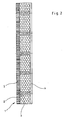
- the thermal insulation board 1 is shown in cross section.
- the thermal insulation board 1 has a kapillarleitfixed layer 4, which is in communication with the capillary conductive areas 2.
- This layer 4 absorbs accumulating condensate and supplies it to the capillary-conductive regions 2.
- the kapillarleitchangeen areas 2 direct the condensate to the outside of the thermal insulation board 1, ie to the interior.
- the material of the vertical capillary layer 4 and the material arranged in the capillary-conductive regions 2 are preferably identical.
- the heat-insulating panel 1 still has a capillary-conductive buffer layer 5.
- the main task of this layer is the buffering of the room air humidity over 24 hours and the delivery and distribution of the condensate transported through the capillary-conductive areas 2.
- This layer 5 also contributes to the breathability and thermal insulation.
- the layer thickness of the insulating layer 3 is about 2/3 of the total thickness, while the vertical capillary layer 4 1/6 and the moisture buffer layer 5 2/6 makes, that is about twice as strong as the vertical capillary 4.
- the insulation layer 3 is prefers the thickest of the three layers.
- the insulating layer with the capillary-conductive openings may have thicknesses between 5 mm and 120 mm, preferably 15 mm and 80 mm, in particular between 20 mm and 60 mm and preferably a thickness of 40 mm.
- the capillary-conductive layer 4 may have thicknesses between 0.1 mm and 20 mm, in particular thicknesses between 1 mm and 5 mm.
- the buffer layer 5 may have thicknesses between 0.5 mm and 40 mm and preferably between 2 mm and 20 mm and in particular in the range of 4 mm to 10 mm.
- the kapillarleitchangeen areas 2 can, unlike shown in the drawing and extend into the vertical capillary layer 4 into or even into the buffer layer 5 or even form the conclusion.
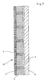
- Fig. 3 an inventive wall structure 10 is shown.
- the previously described insulation board is attached inside or the wall structure has been created in a comparable form on site.
- an insulating layer 3 is arranged with transversely directed to the wall or insulation level capillary conductive areas 2.
- the kapillarleitfounde layer 4 may be part of an insulating board in this wall structure, which is applied or at the same time serve as an adhesive layer with which the insulating layer 2 is attached to the wall 11.
- the layer 4 can also be applied from a material or in such a thickness on the wall 11, that when attaching an insulation board with openings these openings are filled by the capillary conductive material.
- the outer capillary conductive buffer layer 5 can also be created on site or alternatively applied as a finished plate system.
- the buffer layer 5 is formed by a 6 mm thick moisture control plaster.
- the insulating layer 3 is provided, which consists of a 50 mm thick layer of polyurethane or polystyrene. This material is not or only insignificantly capillary conductive per se.
- a square grid with intervals of about 40 mm openings are provided, which are each circular and have a diameter of about 4 mm.
- a capillary conductive mortar is introduced, which thus forms the capillary conductive region 2.
- the grid is designed to that the openings to the edge still half the pitch, so that when assembling two insulation boards, the grid is again formed completely and continuously.
- the capillary layer 4 adjoins the insulating layer 3, which is formed in the preferred embodiment of a capillary-conductive Ansetzmörtel with a layer thickness of 5 mm.
- Such an insulating board is preferably used for internal insulation, but can also be used in principle for external insulation.
Description
Die Erfindung betrifft einen Wandaufbau mit einer Dämmschicht, insbesondere einer innenseitigen Dämmschicht, wobei die Dämmschicht insbesondere als Wärmedämmplatte ausgebildet ist. Weiterhin betrifft die Erfindung eine Wärmedämmplatte mit einer Dämmschicht, insbesondere zur Verwendung in einem Wandaufbau.The invention relates to a wall structure with an insulating layer, in particular an inside insulating layer, wherein the insulating layer is formed in particular as a thermal insulation board. Furthermore, the invention relates to a thermal insulation board with an insulating layer, in particular for use in a wall structure.
Typischerweise werden Gebäude auf der Außenseite des Mauerwerks gedämmt oder mit einem Dämmstoff ausgestattet. Dadurch ist die Temperatur der Wand relativ hoch, weil der Temperaturabfall insbesondere im außenliegenden Dämmstoff stattfindet. Im Fall einer Dämmung der Mauer auf der Innenseite findet der Temperaturabfall im wesentlichen im innenliegenden Dämmstoff statt. Dadurch ist die Temperatur des Mauerwerks viel niedriger als bei einer Außendämmung. Der Dampfdruckgradient ist dann höher und es gelangt mehr Feuchtigkeit in die Wand. Die Kondensatebene befindet sich dann in der Nähe der Dämmschicht auf der Innenseite der Wand. Durch das Kondensat können Bauschäden entstehen.Typically, buildings are insulated on the outside of the masonry or equipped with an insulating material. As a result, the temperature of the wall is relatively high, because the temperature drop takes place in particular in the outer insulating material. In the case of an insulation of the wall on the inside of the temperature drop takes place substantially in the inner insulating material. As a result, the temperature of the masonry is much lower than with an external insulation. The vapor pressure gradient is then higher and more moisture gets into the wall. The condensate level is then close to the insulation layer on the inside of the wall. The condensate can cause structural damage.
Um eine leicht zu verarbeitende Innendämmung zu schaffen, die dieses Problem behebt, wird in der
Die
Der Erfindung liegt die Aufgabe zugrunde, einen Wandaufbau und eine Wärmedämmplatte der eingangs genannten Art zu schaffen, die bei hoher Dämmung diffusionsoffen und preisgünstig herstellbar ist.The invention has for its object to provide a wall structure and a thermal insulation board of the type mentioned, which is open to diffusion with high insulation and inexpensive to produce.
Die Lösung dieser Aufgabe erfolgt mit einem Wandaufbau mit den Merkmalen des Patentanspruchs 1. Hinsichtlich der Wärmedämmplatte erfolgt die Lösung der Aufgabe mit einer Wärmedämmplatte mit den Merkmalen des Patentanspruchs 9. Vorteilhafte Ausgestaltungen der Erfindung sind in den Unteransprüchen beschrieben.The solution of this problem is carried out with a wall structure with the features of claim 1. With regard to the thermal insulation board, the solution of the problem with a thermal insulation board with the features of claim 9. Advantageous embodiments of the invention are described in the subclaims.
Bei einem Wandaufbau mit einer Dämmschicht, insbesondere innenseitigen Dämmschicht, insbesondere einer Wärmedämmplatte, ist erfindungswesentlich vorgesehen, daß die Schicht kapillarleitfähige Bereiche aufweist, die von einer Seite der Dämmschicht zur anderen Seite der Dämmschicht verlaufen. Die kapillarleitfähigen Bereiche sind dabei durchgehend ausgebildet. "Durchgehend" ist im Sinne einer ununterbrochenen kapillaren Leitfähigkeit zu verstehen. Die Seiten der Dämmschicht bezeichnen die dem Innenraum und dem Mauerwerk zugewandten Flächen.In a wall construction with an insulating layer, in particular insulating layer on the inside, in particular a thermal insulation board, it is essential to the invention that the layer has capillary-conductive areas which extend from one side of the insulating layer to the other side of the insulating layer run. The capillary conductive areas are formed continuously. "Through" is to be understood in the sense of an uninterrupted capillary conductivity. The sides of the insulating layer indicate the surfaces facing the interior and the masonry.
Durch die kapillarleitfähigen Bereiche kann Kondensat von der Außenseite der Dämmschicht also der wandseitigen Seite der Dämmschicht abgeführt und zurück in den Innenraum geführt werden. Dadurch werden Feuchtigkeits- und Schimmelprobleme im Mauerbereich vermieden. Außerdem wird die Diffusionsfähigkeit der Konstruktion sichergestellt. Auch kann von Außen eingedrungene Feuchtigkeit nach Innen abgegeben werden und die Konstruktion wird so getrocknet. Dies ist insbesondere an der Schlagregenseite von Relevanz.Due to the kapillarleitfähigen areas condensate can be removed from the outside of the insulating layer so the wall side of the insulating layer and fed back into the interior. This prevents moisture and mildew problems in the wall area. In addition, the diffusibility of the construction is ensured. In addition, moisture penetrated from the outside can be released inside and the construction is dried in this way. This is especially relevant on the driving rain side.
Mit der Erfindung wird eine preisgünstige, sehr gut wärmedämmende Platte bzw. ein solcher Wandaufbau geschaffen, der kapillarleitfähig ist. Im Ergebnis wird dadurch eine diffusionsaktive und kapillarleitfähige Innendämmung geschaffen, die eine mit der heute üblichen Außendämmung vergleichbare Dämmung und Energieeinsparung erreicht.With the invention, a low-cost, very good thermal insulation board or such a wall structure is created, which is kapillarleitfähig. As a result, a diffusion-active and kapillarleitfähige interior insulation is created, which achieves comparable with today's exterior insulation and energy savings.
In einer bevorzugten Ausgestaltung sind die kapillarleitfähigen Bereiche als kapillarleitfähige Durchbrüche ausgebildet, insbesondere als Durchbrüche, die mit einem kapillarleitfähigen Material gefüllt sind. Alternativ können die Durchbrüche selbst so ausgebildet sein, daß diese von sich aus kapillar-leitfähig sind. Dies kann insbesondere bei Schaumstoffplatten erreicht werden, die quer zur Plattenebene verlaufende Kapillaren ausbilden. Die Kapillare können senkrecht oder schräg zur Plattenebene verlaufen. Insbesondere bei dieser Art der Ausführungsform können die kapillarleitfähigen Bereiche flächig ausgebildet sein und nahezu die gesamte Dämmschicht ausmachen. Bevorzugt werden in einem solchen Fall die Wände dieser Durchbrüche mit benetzungsfördemden Stoffen beschichtet. Die kapillarleitfähigen Bereiche machen bevorzugt 1 bis 50 %, insbesondere jedoch weniger als 10 % und in besonders günstigen Ausgestaltungen weniger als 2 % der gedämmten Fläche aus.In a preferred embodiment, the capillary conductive areas are formed as kapillarleitfähige breakthroughs, in particular as openings, which are filled with a capillary conductive material. Alternatively, the openings themselves may be formed so that they are capillary-conductive per se. This can be achieved, in particular, with foam boards which form capillaries extending transversely to the plane of the board. The capillaries can be perpendicular or oblique to the plate plane. In particular, in this type of embodiment, the kapillarleitfähigen areas may be formed flat and make up almost the entire insulation layer. In such a case, the walls of these apertures are preferably coated with wetting-promoting substances. The capillary conductive areas preferably make 1 to 50%, but especially less than 10% and, in particularly favorable configurations, less than 2% of the insulated area.
In einer bevorzugten Ausgestaltung der Erfindung weist der Wandaufbau eine kapillarleitfähige Schicht auf, die wandseitig hinter der Dämmschicht angeordnet und mit den kapillarleitfähigen Bereichen verbunden ist. Eine solche Schicht kann anfallendes Kondensat aufnehmen und den kapillarleitfähigen Bereichen zuführen. Außerdem stellt sie die Atmungsfähigkeit des Wandaufbaus sicher und leistet einen Beitrag zur Wärmedämmung. Diese Schicht kann entweder Bestandteil der Dämmung bzw. der Dämmplatte sein oder ist bevorzugt gleichzeitig eine Klebschicht, mit der die Wärmedämmplatte an einer Mauer befestigt wird. Insbesondere kann dies auch ein Material, beispielsweise ein Mörtel sein, der beim Aufbringen einer Dämmplatte mit Durchbrüchen einerseits die kapillarleitfähige Schicht ausbildet und andererseits gleichzeitig durch die vorgefertigten Durchbrüche in einer Dämmplatte durchtritt und in diesen Durchbrüchen die kapillarleitfähigen Bereiche ausbildet. Der Wandaufbau besteht aus einzelnen Schichten, denen spezifische Aufgaben wie Wärmedämmung, Atmungsfähigkeit oder Feuchtepufferung zugewiesen sind.In a preferred embodiment of the invention, the wall structure on a kapillarleitfähige layer, which is arranged on the wall side behind the insulating layer and connected to the kapillarleitfähigen areas. Such a layer can absorb accumulating condensate and feed the capillary conductive areas. It also ensures the breathability of the wall structure and contributes to thermal insulation. This layer can either be part of the insulation or the insulation board or is preferably at the same time an adhesive layer with which the thermal insulation board is attached to a wall. In particular, this may also be a material, for example a mortar, which on the one hand forms the kapillarleitfähige layer when applying an insulating board with apertures and on the other hand simultaneously passes through the prefabricated openings in an insulating board and forms the kapillarleitfähigen areas in these breakthroughs. The wall structure consists of individual layers that are assigned specific tasks such as thermal insulation, breathability or moisture buffering.
Ein weiterer Aspekt der Erfindung besteht in der Bereitstellung einer Wärmedämmplatte, insbesondere zur Innendämmung, mit einer Dämmschicht, insbesondere zur Verwendung in einem solchen Wandaufbau, wobei die Dämmschicht kapillarleitfähige Bereiche aufweist, die von einer Seite der Dämmschicht zur anderen Seite der Dämmschicht verlaufen. Die kapillarleitfähigen Bereiche sind dabei quer zur Dämmschicht ausgerichtet. Der Begriff "quer" ist hier als geometrische Orientierung in dem Sinne zu verstehen, daß die kapillarleitfähigen Bereiche quer zur Plattenebene verlaufen, also die beiden sich gegenüberliegenden Plattenflächen miteinander verbinden. Dies kann senkrecht oder unter einem Winkel oder schräg zur Plattenebene erfolgen. Bevorzugt sind die kapillarleitfähigen Bereiche senkrecht zur Plattenebene orientiert. Die kapillarleüfähigen Bereiche sind auch hier "durchgehend" durch die Dämmschicht ausgebildet. Insbesondere durchdringen diese Bereiche vollständig die Dämmschicht. Die übrige Dämmschicht ist nicht oder nur unwesentlich kapillarleitfähig, jedenfalls wesentlich weniger kapillarleitfähig als die eingebrachten kapillarleitfähigen Bereiche.Another aspect of the invention is the provision of a thermal insulation board, in particular for internal insulation, with an insulating layer, in particular for use in such a wall structure, wherein the insulating layer capillary conductive areas which extend from one side of the insulating layer to the other side of the insulating layer. The capillary conductive areas are aligned transversely to the insulating layer. The term "transverse" is to be understood here as a geometric orientation in the sense that the kapillarleitfähigen areas extend transversely to the plane of the plate, so connect the two opposite plate surfaces together. This can be done vertically or at an angle or obliquely to the plate plane. The capillary-conductive regions are preferably oriented perpendicular to the plane of the plate. The kapillarleüfähigen areas are also here "continuously" formed by the insulating layer. In particular, these areas completely penetrate the insulating layer. The rest of the insulating layer is not or only slightly capillary conductive, at least much less capillary conductive than the introduced capillary conductive areas.
Bevorzugt sind diese kapillarleitfähigen Bereiche durch Durchbrüche realisiert, in denen ein kapillarleitfähiges Material eingebracht ist. Der Aufbau der Wärmedämmplatte ist bevorzugt in ähnlicher Form ausgestaltet wie der Wandaufbau. Bevorzugt weist die Wärmedämmplatte auf der Seite, die zum wandseitigen Einbau vorgesehen ist, eine kapillarleitfähige Schicht auf, die mit den kapillarleitfähigen Bereichen verbunden ist. Die Materialien der kapillarleitfähigen Schicht und der kapillarleitfähigen Bereiche sind bevorzugt identisch. Es können jedoch auch unterschiedliche Stoffe verbunden werden. Die kapillarleitfähigen Bereiche können dabei auch bis in die kapillarleitfähige Schicht hinein ausgebildet und auch bis zu deren Ende ausgebildet sein. Auf der gegenüberliegenden Seite weist die Wärmedämmplatte bevorzugt eine kapillarleitfähige Feuchtepufferschicht auf. Diese dient zur kurzfristigen Aufnahme von Feuchtigkeit aus dem Innenraum und zur Regulierung des Raumklimas. Diese Schicht trägt auch einen Anteil zur Wärmedämmung bei. Weiterhin kann über diese Schicht auch die durch die kapillarleitfähigen Bereiche hindurch transportierte Feuchtigkeit verteilt und damit über eine größere Oberfläche an den Innenraum abgegeben werden. Alternativ können die kapillarleitfähigen Bereiche auch durch Hohlräume gebildet sein. Insbesondere z.B. bei Verwendung von Schaumstoff oder anderen ähnlichen Materialien kann durch Einbringen einer großen Vielzahl von kleinsten Stichen oder Schnitten eine Kapillarleitfähigkeit erreicht werden. Mit solchen, z.B. mit einer Nadel eingebrachten Stichen wird ein sehr kleiner kapillarleitfähiger Hohlraum bzw. Öffnung geschaffen, in die nicht unbedingt ein anderes Material eingesetzt werden müßte, sondern auch als Hohlraum bzw. bei Füllung mit Luft kapillarleitfähig ist.Preferably, these capillary conductive areas are realized by openings in which a kapillarleitfähiges material is introduced. The structure of the thermal insulation panel is preferably designed in a similar form as the wall structure. Preferably, the heat-insulating board on the side, which is provided for wall-side installation, a capillary conductive layer, which is connected to the capillary conductive areas. The materials of the capillary conductive layer and the capillary conductive regions are preferably identical. However, different substances can be combined. The capillary-conductive regions can also be formed into the capillary-conductive layer and can also be formed up to its end. On the opposite side, the heat-insulating panel preferably has a capillary-conductive moisture buffer layer. This is used for short-term absorption of moisture from the interior and for regulating the indoor climate. This layer also contributes to thermal insulation. Furthermore, the moisture transported through the capillary-conductive regions can be distributed over this layer and thus released to the interior over a larger surface area. Alternatively, the capillary conductive areas may also be formed by cavities. In particular e.g. When foam or other similar materials are used, capillary conductivity can be achieved by introducing a wide variety of minute cuts or cuts. With such, e.g. With a needle introduced stitches a very small kapillarleitfähiger cavity or opening is created, in which not necessarily another material would have to be used, but also as a cavity or when filled with air capillary conductive.
In einer anderen bevorzugten Ausgestaltung der Erfindung ist die Dämmschicht der Dämmplatte und auch die Dämmschicht in dem Wandaufbau dicker als die anderen beschriebenen Schichten. Insbesondere ist die Dämmschicht bevorzugt dicker als die Summe der Dicken der kapillarleitfähigen Schicht und der Feuchtepufferschicht zusammen, bevorzugt sogar dicker als das zweifache der Summe aus kapillarleitfähiger Schicht und Feuchtepufferschicht.In another preferred embodiment of the invention, the insulating layer of the insulating board and the insulating layer in the wall structure thicker than the other layers described. In particular, the insulating layer is preferably thicker than the sum of the thicknesses of the capillary-conductive layer and the moisture buffer layer together, preferably even thicker than twice the sum of kapillarleitfähiger layer and moisture buffer layer.
Die Dämmschicht ist bevorzugt aus bei der Außendämmung gängigen Materialien, wie Mineralwolle und Schaumstoffprodukten hergestellt. Diese weisen typischerweise deutlich günstigere Dämmwerte als Calciumsilikatplatten auf. Die Dämmschicht ist dabei ohne die kapillarleitfähigen Durchbrüche typischerweise nicht oder nur unwesentlich kapillarleitfähig. Materialien, die hier verwendet und mit kapillarleitfähigen Durchbrüchen versehen werden können, sind beispielsweise Schaumglas, Blähperlit, expandiertes Polystyrol, expandiertes Vermiculit, flexibler Elastomerschaum, Mineralwolle, Polyisocyanurat-Schaum, Polyethylenschaum, Phenolharzschaum/hartschaum, Polyurethan-Hartschaum, Harnstoff-Formaldehydharz-Schaum, extrudierter Polystyrolschaum, expandierter Kork, Blähtonleichtzuschlagsstoffe, Holzfaser, Holzwolle und Zellulosefüllstoff. Die kapillarleitende Schicht kann ebenfalls aus einer Vielzahl verschiedener Materialen hergestellt sein, die im folgenden beispielhaft aufgezählt werden. Die kapillarleitfähigen Bereiche können mit Durchbrüchen realisiert sein, die mit einem kapillarleitfähigen Material gefüllt sind. Bevorzugt ist das Material in den Durchbrüchen dasselbe wie das der kapillarleitfähigen Schicht. Dadurch läßt sich die Herstellung vereinfachen. Bei der Herstellung des Wandaufbaus besteht auch die Möglichkeit, eine solche Schicht, z.B. Mörtel, zuerst auf einer Wand oder einer Mauer aufzubringen und Wärmedämmplatten mit vorgefertigten Durchbrüchen in den kapillarleitfähigen Mörtel einzudrücken, so daß dieser aus den Löchern herausquillt und dadurch die kapillarleitfähigen Bereiche ausbildet. Für die kapillarleitfähige Schicht kann ein Mörtel in verschiedenen Zusammensetzungen verwendet werden. Als Füllstoffe können sowohl poröse als auch nicht poröse Formen eingesetzt werden. Als Bindemittel können mineralische Bindemittel wie Zement, Gips, Tonerdeschmelzzement, Silikat oder Phosphat eingesetzt werden. Alternativ können auch Harze als Bindemittel eingesetzt werden. Als Harze können Naturharze, 2-Komponentenharze wie Epoxyharze, PMMA oder PU oder es können auch Dispersionsharze wie Acrylat oder Stryrol-Butadien oder andere eingesetzt werden.The insulating layer is preferably made of materials commonly used in outdoor insulation, such as mineral wool and foam products. These typically have significantly lower insulation values than calcium silicate boards. The insulating layer is typically not or only slightly capillary conductive without the kapillarleitfähigen breakthroughs. Materials which can be used here and provided with capillary-conductive openings are, for example, foam glass, expanded perlite, expanded polystyrene, expanded vermiculite, flexible elastomer foam, mineral wool, polyisocyanurate foam, polyethylene foam, phenolic foam / hard foam, rigid polyurethane foam, urea-formaldehyde resin foam, extruded polystyrene foam, expanded cork, expanded clay lightweight aggregates, wood fiber, wood wool and cellulose filler. The capillary conductive layer may also be made of a variety of different materials, which will be exemplified below. The kapillarleitfähigen areas can be realized with breakthroughs that are filled with a capillary conductive material. Preferably, the material in the apertures is the same as that of the capillary conductive layer. As a result, the production can be simplified. In the manufacture of the wall structure, it is also possible to apply such a layer, such as mortar, first on a wall or wall and press heat insulation panels with prefabricated openings in the capillary conductive mortar, so that it swells out of the holes and thereby forms the kapillarleitfähigen areas. For the capillary conductive layer, a mortar in various compositions can be used. As fillers both porous and non-porous forms can be used. As binders, mineral binders such as cement, gypsum, high-alumina cement, silicate or phosphate can be used. Alternatively you can also resins are used as binders. As resins, natural resins, 2-component resins such as epoxy resins, PMMA or PU, or dispersion resins such as acrylate or styrene-butadiene or others can also be used.
Die sichtseitige, insbesondere innenraumseitige Feuchtepufferschicht ist bevorzugt als Putz ausgebildet. Dieser kann wiederum bevorzugt aus Lehm, einem Klimaputz oder anderen diffusionsfähigen Materialien bestehen. Zur Pufferung können zusätzlich geeignete Materialien wie Glykole, wasserspeichernde Polymere oder ähnliche enthalten sein.The visible, in particular interior side moisture buffer layer is preferably designed as a plaster. This in turn may preferably consist of clay, a Klimaputz or other diffusible materials. For buffering, suitable materials such as glycols, water-storing polymers or the like may additionally be contained.
Es liegt ebenfalls im Bereich der Erfindung die Wärmedämmplatte bzw. den Wandaufbau als Innendämmung, Klimaplatte für Feuchträume und auch für Decke, Wand und Boden einzusetzen. Der Wandaufbau und auch die Wärmedämmplatte können grundsätzlich auch so ausgerichtet werden, daß eine solche Wärmedämmung auf der Außenseite des Mauerwerks angeordnet wird.It is also within the scope of the invention to use the thermal insulation board or the wall structure as interior insulation, climate plate for damp rooms and also for ceiling, wall and floor. The wall structure and also the thermal insulation board can in principle also be oriented so that such thermal insulation is arranged on the outside of the masonry.
Es versteht sich, daß die oben gegebenen Detailbeschreibungen, insbesondere hinsichtlich Materialauswahl und Funktion und in der folgenden Figurenbeschreibung, insbesondere hinsichtlich der Dimensionierung angegebenen Einzelheiten, die entweder für den Wandaufbau oder für Wärmedämmplatte beschrieben sind, umgekehrt auch für die Wärmedämmplatte oder den Wandaufbau zutreffen und beansprucht werden.It is understood that the detailed descriptions given above, in particular with regard to material selection and function and in the following description of the figures, in particular with regard to the dimensions specified details that are described either for the wall structure or for thermal insulation board, apply and apply vice versa for the thermal insulation board or the wall structure become.
Nachfolgend wird die Erfindung anhand eines in der Zeichnung dargestellten bevorzugten Ausführungsbeispiels weiter erläutert. Im Einzelnen zeigen die schematischen Darstellungen in:
- Fig. 1:
- eine Draufsicht auf eine erfindungsgemäße Dämmplatte;
- Fig. 2:
- eine geschnittene Seitenansicht einer erfindungsgemäßen Dämmplatte; und
- Fig. 3:
- eine geschnittene Seitenansicht eines erfindungsgemäßen Wandaufbaus.
- Fig. 1:
- a plan view of an insulation board according to the invention;
- Fig. 2:
- a sectional side view of an insulation board according to the invention; and
- 3:
- a sectional side view of an inventive Wall construction.
In
In
In
Ein konkretes Beispiel sieht dabei so aus, daß die Pufferschicht 5 von einem 6 mm starken Feuchteregulierungsputz gebildet ist. Zentral ist die Dämmschicht 3 vorgesehen, die hier aus einer 50 mm starken Schicht aus Polyurethan oder Polystyrol besteht. Dieses Material ist für sich gesehen nicht oder nur unwesentlich kapillarleitfähig. In einem quadratischen Raster mit Abständen von rund 40 mm sind Durchbrüche vorgesehen, die jeweils kreisförmig sind und einen Durchmesser von etwa 4 mm aufweisen. In den Durchbrüchen ist ein kapillarleitfähiger Mörtel eingebracht, der so den kapillarleitfähigen Bereich 2 ausbildet. Bei Ausbildung einer Dämmplatte ist das Raster so ausgebildet, daß die Durchbrüche zum Rand noch das halbe Rastermaß aufweisen, so daß bei Zusammensetzen zweier Dämmplatten das Raster wieder vollständig und kontinuierlich ausgebildet ist. An die Dämmschicht 3 schließt sich die Kapillarschicht 4 an, die im bevorzugten Ausführungsbeispiel aus einem kapillarleitfähigen Ansetzmörtel mit einer Schichtdicke von 5 mm gebildet ist. Eine solche Dämmplatte wird bevorzugt für die Innendämmung eingesetzt, kann jedoch auch grundsätzlich zur Außendämmung verwendet werden.A concrete example is that the
Claims (16)
- A wall construction comprising an insulation layer (3), in particular an inner insulation layer (3), the insulation layer comprising capillary-conductive regions, which run from one side of the insulation layer to the other side of the insulation layer,
characterised in that
the wall construction (10) comprises a capillary-conductive layer (4), which is arranged behind the insulation layer (3) on the wall side and is connected to the capillary-conductive regions (2),
and in that the wall construction (10) comprises a capillary-conductive moisture buffer layer (5) on the visible side. - The wall construction according to Claim 1, characterised in that the capillary-conductive regions (2) are formed as capillary-conductive apertures, which are filled with a capillary-conductive material.
- The wall construction according to Claim 1, characterised in that the capillary-conductive regions (2) are formed by capillary-active cavities.
- The wall construction according to Claim 3, characterised in that the capillary-conductive layer (4) consists of the same material as the material in the capillary-conductive regions (2).
- The wall construction according to one of Claims 3 or 4, characterised in that the capillary-conductive layer (4) is an adhesive layer.
- The wall construction according to one of the preceding claims, characterised in that the insulation layer (3) is thicker than the capillary-conductive layer (4), and the capillary-conductive moisture buffer layer (5) in particular is more than twice as thick as the sum of the two other layers.
- The wall construction according to one of the preceding claims, characterised in that the apertures have a diameter of approximately 4 mm.
- The wall construction according to one of the preceding claims, characterised in that the apertures occupy approximately 2 % of the area of the insulation layer.
- A thermal insulation plate comprising an insulation layer (3), in particular for a wall construction according to one of Claims 1 to 8, wherein the insulation layer (3) comprises capillary-conductive regions (2), which run continuously from one side of the insulation layer to the other side of the insulation layer,
characterised in that
the thermal insulation plate (1) comprises a capillary-conductive layer (4), which is connected to the capillary-conductive regions (2),
in that the thermal insulation plate (1) comprises a capillary-conductive moisture buffer layer (5),
and in that the capillary-conductive moisture buffer layer (5) and the capillary-conductive layer (4) are arranged on opposite sides of the insulation layer (3). - The thermal insulation plate according to Claim 9, characterised in that the capillary-conductive regions (2) extend perpendicularly through the insulation layer (3).
- The thermal insulation plate according to one of Claims 9 or 10, characterised in that the capillary-conductive regions (2) are formed as capillary-conductive apertures, in particular as apertures that are filled with a capillary-conductive material.
- The thermal insulation plate according to one of Claims 9 to 11, characterised in that the capillary-conductive regions (2) are formed by capillary-active cavities.
- The thermal insulation plate according to one of Claims 9 to 12, characterised in that the insulation layer (3) is thicker than the capillary-conductive layer (4), and the capillary-conductive moisture buffer layer (5) in particular is more than twice as thick as the sum of the two other layers.
- The thermal insulation plate according to one of Claims 9 to 13, characterised in that the apertures in the insulation layer have a diameter of approximately 4 mm.
- The thermal insulation plate according to one of Claims 9 to 14, characterised in that the capillary-conductive regions make up approximately 2 % of the insulated area or less.
- The thermal insulation plate according to one of the preceding claims, characterised in that the capillary-conductive layer and the capillary-conductive regions are formed from different materials.
Priority Applications (3)
| Application Number | Priority Date | Filing Date | Title |
|---|---|---|---|
| PL13181431T PL2666625T3 (en) | 2007-08-30 | 2008-08-29 | Wall construction and thermal insulation panel |
| PL08828126T PL2183099T3 (en) | 2007-08-30 | 2008-08-29 | Wall construction and thermal insulation plate |
| EP13181431.1A EP2666625B1 (en) | 2007-08-30 | 2008-08-29 | Wall construction and thermal insulation panel |
Applications Claiming Priority (2)
| Application Number | Priority Date | Filing Date | Title |
|---|---|---|---|
| DE102007040938.0A DE102007040938B4 (en) | 2007-08-30 | 2007-08-30 | Wall structure and thermal insulation board |
| PCT/DE2008/001419 WO2009026910A1 (en) | 2007-08-30 | 2008-08-29 | Wall construction and thermal insulation plate |
Related Child Applications (2)
| Application Number | Title | Priority Date | Filing Date |
|---|---|---|---|
| EP13181431.1A Division EP2666625B1 (en) | 2007-08-30 | 2008-08-29 | Wall construction and thermal insulation panel |
| EP13181431.1A Division-Into EP2666625B1 (en) | 2007-08-30 | 2008-08-29 | Wall construction and thermal insulation panel |
Publications (3)
| Publication Number | Publication Date |
|---|---|
| EP2183099A1 EP2183099A1 (en) | 2010-05-12 |
| EP2183099B1 true EP2183099B1 (en) | 2013-09-04 |
| EP2183099B2 EP2183099B2 (en) | 2018-08-08 |
Family
ID=39986271
Family Applications (2)
| Application Number | Title | Priority Date | Filing Date |
|---|---|---|---|
| EP08828126.6A Not-in-force EP2183099B2 (en) | 2007-08-30 | 2008-08-29 | Wall construction and thermal insulation plate |
| EP13181431.1A Active EP2666625B1 (en) | 2007-08-30 | 2008-08-29 | Wall construction and thermal insulation panel |
Family Applications After (1)
| Application Number | Title | Priority Date | Filing Date |
|---|---|---|---|
| EP13181431.1A Active EP2666625B1 (en) | 2007-08-30 | 2008-08-29 | Wall construction and thermal insulation panel |
Country Status (5)
| Country | Link |
|---|---|
| EP (2) | EP2183099B2 (en) |
| DE (1) | DE102007040938B4 (en) |
| DK (1) | DK2183099T3 (en) |
| PL (2) | PL2183099T3 (en) |
| WO (1) | WO2009026910A1 (en) |
Families Citing this family (19)
| Publication number | Priority date | Publication date | Assignee | Title |
|---|---|---|---|---|
| GB0908052D0 (en) * | 2009-05-11 | 2009-06-24 | Leaman Browne Ltd | Preparation of coverings |
| DE102010044789A1 (en) | 2010-09-09 | 2012-03-15 | Calsitherm Verwaltungs Gmbh | Thermal insulation plate for masonry wall, has chambers arranged between cover layer plate and barrier layer, where barrier layer is provided as barrier layer plate |
| DE102010044791A1 (en) | 2010-09-09 | 2012-03-15 | Calsitherm Verwaltungs Gmbh | Thermal insulation board, has covering layer plate and barrier layer serving as barrier layer plate, and chambers enclosed by capillary-active chamber bars that are capillary-active connected with covering and barrier layer plates |
| CH704044A1 (en) | 2010-11-02 | 2012-05-15 | Swisspor Man Ag | Insulation. |
| AT513134B1 (en) | 2012-11-15 | 2014-02-15 | Lb Engineering Gmbh | Cladding element for a building |
| EP2765251B1 (en) | 2013-02-12 | 2016-12-28 | Daw Se | Plate-shaped thermal insulation composite and thermal insulation composite area, in particular thermal insulation panel area, comprising plate-shaped thermal insulation composites, process for the preparation of thermal insulation composites, and use of thermal insulation composites for the thermal insulation of buildings |
| CN104234256A (en) * | 2013-09-02 | 2014-12-24 | 吴淑环 | Energy-saving heat-insulating wall body |
| CN104420550A (en) * | 2013-09-02 | 2015-03-18 | 吴淑环 | Energy-saving heat insulation wall |
| CN104420556A (en) * | 2013-09-02 | 2015-03-18 | 吴淑环 | Assembly type energy-saving wall |
| EP2860319A1 (en) | 2013-10-11 | 2015-04-15 | Daw Se | Thermal insulation composite and thermal insulation composite area and wall structure, comprising the thermal insulation composite or the thermal insulation composite area, and method for the preparation of wall structures |
| EP2921465A1 (en) | 2014-03-20 | 2015-09-23 | PROMAT GmbH | Use of an insulating body as an air conditioning panel |
| EP2990556B1 (en) | 2014-08-25 | 2016-10-26 | STO SE & Co. KGaA | Heat insulating panel made of a polymer particle foam and method for producing such a heat insulating panel |
| EP3031992B1 (en) | 2014-12-10 | 2018-02-14 | Daw Se | Thermal insulation composite and thermal insulation composite area and wall structure, comprising the thermal insulation composite or the thermal insulation composite area, and method for the preparation of wall structures |
| CN104499599B (en) * | 2014-12-12 | 2017-09-01 | 南京工程学院 | Low-temp radiating Climate Control Module wall based on capillary web frame |
| EP3045600A1 (en) * | 2015-01-16 | 2016-07-20 | Evonik Degussa GmbH | Thermal insulation body comprising capillary active elements |
| EP3053895B1 (en) | 2015-02-03 | 2020-04-15 | Daw Se | Preparation masses for porous substrates capable of capillary conduction and porous substrates capable of capillary conduction obtained from said preparation masses |
| DE102017008981A1 (en) * | 2017-09-26 | 2019-03-28 | Karl-Oskar Erley | Insulation Board |
| DE102018112260A1 (en) | 2018-05-22 | 2019-11-28 | Saint-Gobain Isover G+H Ag | Thermal insulation element, building construction and method for preventing moisture damage to a structure |
| DE102022120866A1 (en) | 2022-08-18 | 2024-02-29 | Remmers Gmbh | Method for producing a wall structure with internal insulation |
Family Cites Families (18)
| Publication number | Priority date | Publication date | Assignee | Title |
|---|---|---|---|---|
| AT368573B (en) | 1979-09-06 | 1982-10-25 | Krassnitzer Theobald Ing | THERMAL INSULATION FOR MASONRY |
| FR2520406A1 (en) * | 1982-01-22 | 1983-07-29 | Gachot Jean | THERMALLY INSULATING COATING APPLIED ON BUILDING WALLS AND METHOD OF USE |
| DE3317628A1 (en) * | 1983-05-14 | 1984-11-15 | Kalkspatgruben und Labranit-Edelputzwerk Heinrich Lahme, 5790 Brilon | Thermal insulating board with plaster lath |
| FR2552140B1 (en) † | 1983-09-21 | 1987-11-13 | Eternit Financiere | PLATE FOR WALL INSULATION THERMAL COATING |
| DE3610932A1 (en) † | 1984-10-03 | 1987-10-15 | Horst Dipl Ing Kempin | Process for strengthening concrete structures, in particular walls, pillars or the like of stone-chip concrete, and for producing mortars, concretes or products composed of these in a single-phase or two-phase mixture using an adhesive cement, and an adhesive cement designed for this purpose |
| WO1992010624A1 (en) | 1990-12-12 | 1992-06-25 | Kenitex S.A. | Method for fastening an element to a surface in order to increase the overall heat insulation coefficient of a building wall |
| DE19706223C2 (en) * | 1997-02-18 | 2000-11-30 | Cape Calsil Deutschland Gmbh | Wall renovation panel for salt-contaminated walls |
| DE19921284A1 (en) † | 1999-05-07 | 2000-11-09 | Gruenzweig & Hartmann | Coated mineral wool product and process for its production |
| ES2161608B1 (en) * | 1999-06-03 | 2002-06-16 | Vidal Maurell Joan | PROCEDURE FOR OBTAINING A CONSTRUCTION MATERIAL. |
| DE10146174C2 (en) | 2001-09-19 | 2003-10-16 | Calsitherm Silikatbaustoffe | Thermal insulation board for indoor installation |
| DE20305348U1 (en) | 2003-04-02 | 2003-06-05 | Veit Dennert Kg Baustoffbetr | Heat insulation has vapor blocking or decelerating layer provided between heat insulating layer and stabilizing moisture-absorbing layer |
| US20060032171A1 (en) * | 2004-07-27 | 2006-02-16 | Weir Charles R | Wall insulation system providing improved moisture control |
| DE102004050207A1 (en) | 2004-10-15 | 2006-04-20 | Haase, Werner, Dipl.-Ing. | Internal wall fitting for insulating building walls comprises internal insulation adjoining inside of outside wall and adjoined by internal wall layer which contains several pipes for passing through heating or cooling medium |
| DE202005005231U1 (en) † | 2005-03-31 | 2005-08-04 | Haacke Treuhand Gmbh Celle + Co. Kg | Half timbered house, has moisture wicking material panels or boards pressed against clay layer applied to inner side of house wall as thermal insulation |
| SI1900884T1 (en) | 2006-07-19 | 2009-02-28 | Pavatex Sa | Soft woodfibre panel for internal insulation |
| DE102007025303B4 (en) | 2007-05-30 | 2014-06-26 | Haacke Treuhand Gmbh | Building element for internal insulation of buildings and method for its production |
| DE102007027470A1 (en) † | 2007-06-14 | 2008-12-24 | Construction Research & Technology Gmbh | Polymer-modified building material dry mixtures |
| DE102007027477A1 (en) † | 2007-06-14 | 2009-01-02 | Construction Research & Technology Gmbh | Building material dry mixtures based on calcium sulfate |
-
2007
- 2007-08-30 DE DE102007040938.0A patent/DE102007040938B4/en active Active
-
2008
- 2008-08-29 PL PL08828126T patent/PL2183099T3/en unknown
- 2008-08-29 EP EP08828126.6A patent/EP2183099B2/en not_active Not-in-force
- 2008-08-29 WO PCT/DE2008/001419 patent/WO2009026910A1/en active Application Filing
- 2008-08-29 PL PL13181431T patent/PL2666625T3/en unknown
- 2008-08-29 EP EP13181431.1A patent/EP2666625B1/en active Active
- 2008-08-29 DK DK08828126.6T patent/DK2183099T3/en active
Also Published As
| Publication number | Publication date |
|---|---|
| DK2183099T3 (en) | 2013-12-16 |
| DE102007040938B4 (en) | 2023-09-21 |
| EP2183099A1 (en) | 2010-05-12 |
| EP2666625A1 (en) | 2013-11-27 |
| WO2009026910A1 (en) | 2009-03-05 |
| PL2183099T3 (en) | 2014-02-28 |
| DE102007040938A1 (en) | 2008-12-18 |
| EP2666625B1 (en) | 2017-05-03 |
| EP2183099B2 (en) | 2018-08-08 |
| PL2666625T3 (en) | 2017-10-31 |
Similar Documents
| Publication | Publication Date | Title |
|---|---|---|
| EP2183099B1 (en) | Wall construction and thermal insulation plate | |
| DE202009008493U1 (en) | Wall construction and thermal insulation board | |
| EP2639394A2 (en) | Wall edge strip, window border and wall construction with wall edge strip | |
| CH702833A1 (en) | Wall for separating the inside of a building from the outside. | |
| DE10146174C2 (en) | Thermal insulation board for indoor installation | |
| DE3223098A1 (en) | WALL ELEMENT FOR FERTIGHAEUSER | |
| EP2169132A2 (en) | Slab-shaped construction element | |
| WO2016091244A2 (en) | Panel system for creating rooms | |
| EP2143849A2 (en) | Wall cladding and method for drying a wall surface | |
| EP0697487A1 (en) | Wall, floor or roof element in panel form for buildings | |
| EP1566264B2 (en) | Heat insulating panel | |
| AT17112U1 (en) | Wall or roof cladding unit, wall and roof cladding system, in particular back-ventilated or rear-ventilated wall and roof cladding system, as well as wall, in particular wooden frame construction wall, and roof and use of the wall or roof cladding unit | |
| EP2522785B1 (en) | Method and system for insulating the interior of external building walls | |
| EP2739800A1 (en) | Multi-layer component | |
| DE2831252A1 (en) | Load-bearing heat insulated wall building block - has partitioned insulation filled chambers and vertical water retaining channels | |
| DE102009038773B4 (en) | Interior insulation panel with a hydrophilic, porous body | |
| DE2514259A1 (en) | Ventilated layered ceiling or wall structure panel - with waterproof and vapour repellent insulating layers, and spacers forming ducts | |
| DE2729474A1 (en) | Wall for prefabricated building - has wood frame with lightweight filling and brick or stone cladding glued to plastics foam | |
| DE8217728U1 (en) | WALL ELEMENT FOR FINISHED HOUSES | |
| DE3504110C2 (en) | ||
| DE3021537A1 (en) | Thermal insulation for tall or underground buildings - esp. where profiled polymer sheet forms air cushion between two aluminium sheets or foils | |
| DE3909157A1 (en) | Roof covering having metal profile sheets | |
| DE3129231A1 (en) | Multilayer element for receiving insulating materials | |
| DE102016012948A1 (en) | Prefabricated, multifunctional ceiling | |
| EP1596021A2 (en) | Wall element with a layer of clay or loam |
Legal Events
| Date | Code | Title | Description |
|---|---|---|---|
| PUAI | Public reference made under article 153(3) epc to a published international application that has entered the european phase |
Free format text: ORIGINAL CODE: 0009012 |
|
| 17P | Request for examination filed |
Effective date: 20100212 |
|
| AK | Designated contracting states |
Kind code of ref document: A1 Designated state(s): AT BE BG CH CY CZ DE DK EE ES FI FR GB GR HR HU IE IS IT LI LT LU LV MC MT NL NO PL PT RO SE SI SK TR |
|
| AX | Request for extension of the european patent |
Extension state: AL BA MK RS |
|
| DAX | Request for extension of the european patent (deleted) | ||
| GRAP | Despatch of communication of intention to grant a patent |
Free format text: ORIGINAL CODE: EPIDOSNIGR1 |
|
| GRAS | Grant fee paid |
Free format text: ORIGINAL CODE: EPIDOSNIGR3 |
|
| INTG | Intention to grant announced |
Effective date: 20130417 |
|
| GRAA | (expected) grant |
Free format text: ORIGINAL CODE: 0009210 |
|
| AK | Designated contracting states |
Kind code of ref document: B1 Designated state(s): AT BE BG CH CY CZ DE DK EE ES FI FR GB GR HR HU IE IS IT LI LT LU LV MC MT NL NO PL PT RO SE SI SK TR |
|
| REG | Reference to a national code |
Ref country code: GB Ref legal event code: FG4D Free format text: NOT ENGLISH |
|
| REG | Reference to a national code |
Ref country code: CH Ref legal event code: EP |
|
| REG | Reference to a national code |
Ref country code: AT Ref legal event code: REF Ref document number: 630243 Country of ref document: AT Kind code of ref document: T Effective date: 20130915 |
|
| REG | Reference to a national code |
Ref country code: IE Ref legal event code: FG4D Free format text: LANGUAGE OF EP DOCUMENT: GERMAN |
|
| REG | Reference to a national code |
Ref country code: DE Ref legal event code: R096 Ref document number: 502008010614 Country of ref document: DE Effective date: 20131024 |
|
| REG | Reference to a national code |
Ref country code: CH Ref legal event code: NV Representative=s name: PATENTANWAELTE SCHAAD, BALASS, MENZL AND PARTN, CH |
|
| REG | Reference to a national code |
Ref country code: NL Ref legal event code: T3 |
|
| REG | Reference to a national code |
Ref country code: DK Ref legal event code: T3 Effective date: 20131212 |
|
| PG25 | Lapsed in a contracting state [announced via postgrant information from national office to epo] |
Ref country code: CY Free format text: LAPSE BECAUSE OF FAILURE TO SUBMIT A TRANSLATION OF THE DESCRIPTION OR TO PAY THE FEE WITHIN THE PRESCRIBED TIME-LIMIT Effective date: 20130828 Ref country code: HR Free format text: LAPSE BECAUSE OF FAILURE TO SUBMIT A TRANSLATION OF THE DESCRIPTION OR TO PAY THE FEE WITHIN THE PRESCRIBED TIME-LIMIT Effective date: 20130904 Ref country code: SE Free format text: LAPSE BECAUSE OF FAILURE TO SUBMIT A TRANSLATION OF THE DESCRIPTION OR TO PAY THE FEE WITHIN THE PRESCRIBED TIME-LIMIT Effective date: 20130904 Ref country code: NO Free format text: LAPSE BECAUSE OF FAILURE TO SUBMIT A TRANSLATION OF THE DESCRIPTION OR TO PAY THE FEE WITHIN THE PRESCRIBED TIME-LIMIT Effective date: 20131204 Ref country code: LT Free format text: LAPSE BECAUSE OF FAILURE TO SUBMIT A TRANSLATION OF THE DESCRIPTION OR TO PAY THE FEE WITHIN THE PRESCRIBED TIME-LIMIT Effective date: 20130904 |
|
| PLBI | Opposition filed |
Free format text: ORIGINAL CODE: 0009260 |
|
| REG | Reference to a national code |
Ref country code: LT Ref legal event code: MG4D |
|
| PG25 | Lapsed in a contracting state [announced via postgrant information from national office to epo] |
Ref country code: LV Free format text: LAPSE BECAUSE OF FAILURE TO SUBMIT A TRANSLATION OF THE DESCRIPTION OR TO PAY THE FEE WITHIN THE PRESCRIBED TIME-LIMIT Effective date: 20130904 Ref country code: ES Free format text: LAPSE BECAUSE OF FAILURE TO SUBMIT A TRANSLATION OF THE DESCRIPTION OR TO PAY THE FEE WITHIN THE PRESCRIBED TIME-LIMIT Effective date: 20130904 Ref country code: FI Free format text: LAPSE BECAUSE OF FAILURE TO SUBMIT A TRANSLATION OF THE DESCRIPTION OR TO PAY THE FEE WITHIN THE PRESCRIBED TIME-LIMIT Effective date: 20130904 Ref country code: SI Free format text: LAPSE BECAUSE OF FAILURE TO SUBMIT A TRANSLATION OF THE DESCRIPTION OR TO PAY THE FEE WITHIN THE PRESCRIBED TIME-LIMIT Effective date: 20130904 Ref country code: GR Free format text: LAPSE BECAUSE OF FAILURE TO SUBMIT A TRANSLATION OF THE DESCRIPTION OR TO PAY THE FEE WITHIN THE PRESCRIBED TIME-LIMIT Effective date: 20131205 |
|
| REG | Reference to a national code |
Ref country code: PL Ref legal event code: T3 |
|
| 26 | Opposition filed |
Opponent name: DAW SE Effective date: 20140123 |
|
| PG25 | Lapsed in a contracting state [announced via postgrant information from national office to epo] |
Ref country code: CY Free format text: LAPSE BECAUSE OF FAILURE TO SUBMIT A TRANSLATION OF THE DESCRIPTION OR TO PAY THE FEE WITHIN THE PRESCRIBED TIME-LIMIT Effective date: 20130904 |
|
| REG | Reference to a national code |
Ref country code: DE Ref legal event code: R026 Ref document number: 502008010614 Country of ref document: DE Effective date: 20140123 |
|
| PG25 | Lapsed in a contracting state [announced via postgrant information from national office to epo] |
Ref country code: RO Free format text: LAPSE BECAUSE OF FAILURE TO SUBMIT A TRANSLATION OF THE DESCRIPTION OR TO PAY THE FEE WITHIN THE PRESCRIBED TIME-LIMIT Effective date: 20130904 Ref country code: SK Free format text: LAPSE BECAUSE OF FAILURE TO SUBMIT A TRANSLATION OF THE DESCRIPTION OR TO PAY THE FEE WITHIN THE PRESCRIBED TIME-LIMIT Effective date: 20130904 Ref country code: IS Free format text: LAPSE BECAUSE OF FAILURE TO SUBMIT A TRANSLATION OF THE DESCRIPTION OR TO PAY THE FEE WITHIN THE PRESCRIBED TIME-LIMIT Effective date: 20140104 Ref country code: EE Free format text: LAPSE BECAUSE OF FAILURE TO SUBMIT A TRANSLATION OF THE DESCRIPTION OR TO PAY THE FEE WITHIN THE PRESCRIBED TIME-LIMIT Effective date: 20130904 |
|
| PLBI | Opposition filed |
Free format text: ORIGINAL CODE: 0009260 |
|
| PLBI | Opposition filed |
Free format text: ORIGINAL CODE: 0009260 |
|
| PG25 | Lapsed in a contracting state [announced via postgrant information from national office to epo] |
Ref country code: PT Free format text: LAPSE BECAUSE OF FAILURE TO SUBMIT A TRANSLATION OF THE DESCRIPTION OR TO PAY THE FEE WITHIN THE PRESCRIBED TIME-LIMIT Effective date: 20140106 |
|
| 26 | Opposition filed |
Opponent name: CALSITHERM VERWALTUNGS GMBH Effective date: 20140530 |
|
| PLAX | Notice of opposition and request to file observation + time limit sent |
Free format text: ORIGINAL CODE: EPIDOSNOBS2 |
|
| 26 | Opposition filed |
Opponent name: HAACKE TREUHAND GMBH Effective date: 20140604 |
|
| PLBB | Reply of patent proprietor to notice(s) of opposition received |
Free format text: ORIGINAL CODE: EPIDOSNOBS3 |
|
| PG25 | Lapsed in a contracting state [announced via postgrant information from national office to epo] |
Ref country code: MC Free format text: LAPSE BECAUSE OF FAILURE TO SUBMIT A TRANSLATION OF THE DESCRIPTION OR TO PAY THE FEE WITHIN THE PRESCRIBED TIME-LIMIT Effective date: 20130904 Ref country code: LU Free format text: LAPSE BECAUSE OF FAILURE TO SUBMIT A TRANSLATION OF THE DESCRIPTION OR TO PAY THE FEE WITHIN THE PRESCRIBED TIME-LIMIT Effective date: 20140829 |
|
| REG | Reference to a national code |
Ref country code: FR Ref legal event code: PLFP Year of fee payment: 8 |
|
| PGFP | Annual fee paid to national office [announced via postgrant information from national office to epo] |
Ref country code: DK Payment date: 20150825 Year of fee payment: 8 Ref country code: IE Payment date: 20150819 Year of fee payment: 8 |
|
| PGFP | Annual fee paid to national office [announced via postgrant information from national office to epo] |
Ref country code: FR Payment date: 20150824 Year of fee payment: 8 |
|
| APBM | Appeal reference recorded |
Free format text: ORIGINAL CODE: EPIDOSNREFNO |
|
| APBP | Date of receipt of notice of appeal recorded |
Free format text: ORIGINAL CODE: EPIDOSNNOA2O |
|
| APAH | Appeal reference modified |
Free format text: ORIGINAL CODE: EPIDOSCREFNO |
|
| APBM | Appeal reference recorded |
Free format text: ORIGINAL CODE: EPIDOSNREFNO |
|
| APBP | Date of receipt of notice of appeal recorded |
Free format text: ORIGINAL CODE: EPIDOSNNOA2O |
|
| APBM | Appeal reference recorded |
Free format text: ORIGINAL CODE: EPIDOSNREFNO |
|
| APBP | Date of receipt of notice of appeal recorded |
Free format text: ORIGINAL CODE: EPIDOSNNOA2O |
|
| APBQ | Date of receipt of statement of grounds of appeal recorded |
Free format text: ORIGINAL CODE: EPIDOSNNOA3O |
|
| APBQ | Date of receipt of statement of grounds of appeal recorded |
Free format text: ORIGINAL CODE: EPIDOSNNOA3O |
|
| APBQ | Date of receipt of statement of grounds of appeal recorded |
Free format text: ORIGINAL CODE: EPIDOSNNOA3O |
|
| PG25 | Lapsed in a contracting state [announced via postgrant information from national office to epo] |
Ref country code: BG Free format text: LAPSE BECAUSE OF FAILURE TO SUBMIT A TRANSLATION OF THE DESCRIPTION OR TO PAY THE FEE WITHIN THE PRESCRIBED TIME-LIMIT Effective date: 20130904 |
|
| PG25 | Lapsed in a contracting state [announced via postgrant information from national office to epo] |
Ref country code: MT Free format text: LAPSE BECAUSE OF FAILURE TO SUBMIT A TRANSLATION OF THE DESCRIPTION OR TO PAY THE FEE WITHIN THE PRESCRIBED TIME-LIMIT Effective date: 20130904 |
|
| PG25 | Lapsed in a contracting state [announced via postgrant information from national office to epo] |
Ref country code: TR Free format text: LAPSE BECAUSE OF FAILURE TO SUBMIT A TRANSLATION OF THE DESCRIPTION OR TO PAY THE FEE WITHIN THE PRESCRIBED TIME-LIMIT Effective date: 20130904 Ref country code: HU Free format text: LAPSE BECAUSE OF FAILURE TO SUBMIT A TRANSLATION OF THE DESCRIPTION OR TO PAY THE FEE WITHIN THE PRESCRIBED TIME-LIMIT; INVALID AB INITIO Effective date: 20080829 |
|
| PGFP | Annual fee paid to national office [announced via postgrant information from national office to epo] |
Ref country code: NL Payment date: 20160824 Year of fee payment: 9 |
|
| PGFP | Annual fee paid to national office [announced via postgrant information from national office to epo] |
Ref country code: CH Payment date: 20160824 Year of fee payment: 9 Ref country code: IT Payment date: 20160823 Year of fee payment: 9 Ref country code: GB Payment date: 20160824 Year of fee payment: 9 Ref country code: DE Payment date: 20160706 Year of fee payment: 9 |
|
| PGFP | Annual fee paid to national office [announced via postgrant information from national office to epo] |
Ref country code: CZ Payment date: 20160818 Year of fee payment: 9 Ref country code: AT Payment date: 20160822 Year of fee payment: 9 Ref country code: PL Payment date: 20160817 Year of fee payment: 9 |
|
| PGFP | Annual fee paid to national office [announced via postgrant information from national office to epo] |
Ref country code: BE Payment date: 20160824 Year of fee payment: 9 |
|
| REG | Reference to a national code |
Ref country code: DK Ref legal event code: EBP Effective date: 20160831 |
|
| REG | Reference to a national code |
Ref country code: FR Ref legal event code: ST Effective date: 20170428 |
|
| REG | Reference to a national code |
Ref country code: IE Ref legal event code: MM4A |
|
| PG25 | Lapsed in a contracting state [announced via postgrant information from national office to epo] |
Ref country code: IE Free format text: LAPSE BECAUSE OF NON-PAYMENT OF DUE FEES Effective date: 20160829 Ref country code: DK Free format text: LAPSE BECAUSE OF NON-PAYMENT OF DUE FEES Effective date: 20160831 Ref country code: FR Free format text: LAPSE BECAUSE OF NON-PAYMENT OF DUE FEES Effective date: 20160831 |
|
| REG | Reference to a national code |
Ref country code: DE Ref legal event code: R119 Ref document number: 502008010614 Country of ref document: DE |
|
| REG | Reference to a national code |
Ref country code: CH Ref legal event code: PL |
|
| REG | Reference to a national code |
Ref country code: NL Ref legal event code: MM Effective date: 20170901 |
|
| APBU | Appeal procedure closed |
Free format text: ORIGINAL CODE: EPIDOSNNOA9O |
|
| APAN | Information on closure of appeal procedure modified |
Free format text: ORIGINAL CODE: EPIDOSCNOA9O |
|
| APBC | Information on closure of appeal procedure deleted |
Free format text: ORIGINAL CODE: EPIDOSDNOA9O |
|
| APBU | Appeal procedure closed |
Free format text: ORIGINAL CODE: EPIDOSNNOA9O |
|
| REG | Reference to a national code |
Ref country code: AT Ref legal event code: MM01 Ref document number: 630243 Country of ref document: AT Kind code of ref document: T Effective date: 20170829 |
|
| GBPC | Gb: european patent ceased through non-payment of renewal fee |
Effective date: 20170829 |
|
| PG25 | Lapsed in a contracting state [announced via postgrant information from national office to epo] |
Ref country code: LI Free format text: LAPSE BECAUSE OF NON-PAYMENT OF DUE FEES Effective date: 20170831 Ref country code: CZ Free format text: LAPSE BECAUSE OF NON-PAYMENT OF DUE FEES Effective date: 20170829 Ref country code: CH Free format text: LAPSE BECAUSE OF NON-PAYMENT OF DUE FEES Effective date: 20170831 |
|
| PG25 | Lapsed in a contracting state [announced via postgrant information from national office to epo] |
Ref country code: AT Free format text: LAPSE BECAUSE OF NON-PAYMENT OF DUE FEES Effective date: 20170829 |
|
| REG | Reference to a national code |
Ref country code: BE Ref legal event code: MM Effective date: 20170831 |
|
| PG25 | Lapsed in a contracting state [announced via postgrant information from national office to epo] |
Ref country code: NL Free format text: LAPSE BECAUSE OF NON-PAYMENT OF DUE FEES Effective date: 20170901 |
|
| PUAH | Patent maintained in amended form |
Free format text: ORIGINAL CODE: 0009272 |
|
| STAA | Information on the status of an ep patent application or granted ep patent |
Free format text: STATUS: PATENT MAINTAINED AS AMENDED |
|
| PG25 | Lapsed in a contracting state [announced via postgrant information from national office to epo] |
Ref country code: DE Free format text: LAPSE BECAUSE OF NON-PAYMENT OF DUE FEES Effective date: 20180301 Ref country code: GB Free format text: LAPSE BECAUSE OF NON-PAYMENT OF DUE FEES Effective date: 20170829 |
|
| 27A | Patent maintained in amended form |
Effective date: 20180808 |
|
| AK | Designated contracting states |
Kind code of ref document: B2 Designated state(s): AT BE BG CH CY CZ DE DK EE ES FI FR GB GR HR HU IE IS IT LI LT LU LV MC MT NL NO PL PT RO SE SI SK TR |
|
| REG | Reference to a national code |
Ref country code: DE Ref legal event code: R102 Ref document number: 502008010614 Country of ref document: DE |
|
| PG25 | Lapsed in a contracting state [announced via postgrant information from national office to epo] |
Ref country code: IT Free format text: LAPSE BECAUSE OF NON-PAYMENT OF DUE FEES Effective date: 20170829 Ref country code: BE Free format text: LAPSE BECAUSE OF NON-PAYMENT OF DUE FEES Effective date: 20170831 |
|
| PG25 | Lapsed in a contracting state [announced via postgrant information from national office to epo] |
Ref country code: PL Free format text: LAPSE BECAUSE OF NON-PAYMENT OF DUE FEES Effective date: 20170829 |