EP1566264B2 - Heat insulating panel - Google Patents
Heat insulating panel Download PDFInfo
- Publication number
- EP1566264B2 EP1566264B2 EP04003612A EP04003612A EP1566264B2 EP 1566264 B2 EP1566264 B2 EP 1566264B2 EP 04003612 A EP04003612 A EP 04003612A EP 04003612 A EP04003612 A EP 04003612A EP 1566264 B2 EP1566264 B2 EP 1566264B2
- Authority
- EP
- European Patent Office
- Prior art keywords
- thermal insulation
- insulation member
- member according
- heat
- mouldings
- Prior art date
- Legal status (The legal status is an assumption and is not a legal conclusion. Google has not performed a legal analysis and makes no representation as to the accuracy of the status listed.)
- Expired - Lifetime
Links
- 238000009413 insulation Methods 0.000 claims abstract description 53
- 238000000465 moulding Methods 0.000 claims abstract description 51
- 239000012774 insulation material Substances 0.000 claims abstract description 7
- 239000000463 material Substances 0.000 claims description 8
- VYPSYNLAJGMNEJ-UHFFFAOYSA-N Silicium dioxide Chemical compound O=[Si]=O VYPSYNLAJGMNEJ-UHFFFAOYSA-N 0.000 claims description 7
- 239000006260 foam Substances 0.000 claims description 6
- XAGFODPZIPBFFR-UHFFFAOYSA-N aluminium Chemical compound [Al] XAGFODPZIPBFFR-UHFFFAOYSA-N 0.000 claims description 5
- 229910052782 aluminium Inorganic materials 0.000 claims description 5
- 239000004794 expanded polystyrene Substances 0.000 claims description 4
- 230000000295 complement effect Effects 0.000 claims description 3
- 239000004033 plastic Substances 0.000 claims description 3
- 239000000377 silicon dioxide Substances 0.000 claims description 3
- 239000000126 substance Substances 0.000 claims description 2
- 239000004411 aluminium Substances 0.000 claims 1
- 229910052681 coesite Inorganic materials 0.000 claims 1
- 229910052906 cristobalite Inorganic materials 0.000 claims 1
- RMAQACBXLXPBSY-UHFFFAOYSA-N silicic acid Chemical compound O[Si](O)(O)O RMAQACBXLXPBSY-UHFFFAOYSA-N 0.000 claims 1
- 235000012239 silicon dioxide Nutrition 0.000 claims 1
- 229910052682 stishovite Inorganic materials 0.000 claims 1
- 229910052905 tridymite Inorganic materials 0.000 claims 1
- 238000011161 development Methods 0.000 description 5
- 230000018109 developmental process Effects 0.000 description 5
- 238000004519 manufacturing process Methods 0.000 description 4
- 238000010276 construction Methods 0.000 description 3
- 230000015572 biosynthetic process Effects 0.000 description 2
- 230000006978 adaptation Effects 0.000 description 1
- 239000002131 composite material Substances 0.000 description 1
- 238000013016 damping Methods 0.000 description 1
- 230000001419 dependent effect Effects 0.000 description 1
- 238000005516 engineering process Methods 0.000 description 1
- 238000005187 foaming Methods 0.000 description 1
- 239000011888 foil Substances 0.000 description 1
- 239000011810 insulating material Substances 0.000 description 1
- 210000001503 joint Anatomy 0.000 description 1
- 239000012229 microporous material Substances 0.000 description 1
- 239000004570 mortar (masonry) Substances 0.000 description 1
- 239000011505 plaster Substances 0.000 description 1
- 230000035939 shock Effects 0.000 description 1
Images
Classifications
-
- B—PERFORMING OPERATIONS; TRANSPORTING
- B32—LAYERED PRODUCTS
- B32B—LAYERED PRODUCTS, i.e. PRODUCTS BUILT-UP OF STRATA OF FLAT OR NON-FLAT, e.g. CELLULAR OR HONEYCOMB, FORM
- B32B5/00—Layered products characterised by the non- homogeneity or physical structure, i.e. comprising a fibrous, filamentary, particulate or foam layer; Layered products characterised by having a layer differing constitutionally or physically in different parts
- B32B5/18—Layered products characterised by the non- homogeneity or physical structure, i.e. comprising a fibrous, filamentary, particulate or foam layer; Layered products characterised by having a layer differing constitutionally or physically in different parts characterised by features of a layer of foamed material
-
- B—PERFORMING OPERATIONS; TRANSPORTING
- B32—LAYERED PRODUCTS
- B32B—LAYERED PRODUCTS, i.e. PRODUCTS BUILT-UP OF STRATA OF FLAT OR NON-FLAT, e.g. CELLULAR OR HONEYCOMB, FORM
- B32B3/00—Layered products comprising a layer with external or internal discontinuities or unevennesses, or a layer of non-planar shape; Layered products comprising a layer having particular features of form
- B32B3/02—Layered products comprising a layer with external or internal discontinuities or unevennesses, or a layer of non-planar shape; Layered products comprising a layer having particular features of form characterised by features of form at particular places, e.g. in edge regions
- B32B3/06—Layered products comprising a layer with external or internal discontinuities or unevennesses, or a layer of non-planar shape; Layered products comprising a layer having particular features of form characterised by features of form at particular places, e.g. in edge regions for securing layers together; for attaching the product to another member, e.g. to a support, or to another product, e.g. groove/tongue, interlocking
-
- B—PERFORMING OPERATIONS; TRANSPORTING
- B32—LAYERED PRODUCTS
- B32B—LAYERED PRODUCTS, i.e. PRODUCTS BUILT-UP OF STRATA OF FLAT OR NON-FLAT, e.g. CELLULAR OR HONEYCOMB, FORM
- B32B7/00—Layered products characterised by the relation between layers; Layered products characterised by the relative orientation of features between layers, or by the relative values of a measurable parameter between layers, i.e. products comprising layers having different physical, chemical or physicochemical properties; Layered products characterised by the interconnection of layers
- B32B7/03—Layered products characterised by the relation between layers; Layered products characterised by the relative orientation of features between layers, or by the relative values of a measurable parameter between layers, i.e. products comprising layers having different physical, chemical or physicochemical properties; Layered products characterised by the interconnection of layers with respect to the orientation of features
-
- E—FIXED CONSTRUCTIONS
- E04—BUILDING
- E04B—GENERAL BUILDING CONSTRUCTIONS; WALLS, e.g. PARTITIONS; ROOFS; FLOORS; CEILINGS; INSULATION OR OTHER PROTECTION OF BUILDINGS
- E04B1/00—Constructions in general; Structures which are not restricted either to walls, e.g. partitions, or floors or ceilings or roofs
- E04B1/62—Insulation or other protection; Elements or use of specified material therefor
- E04B1/74—Heat, sound or noise insulation, absorption, or reflection; Other building methods affording favourable thermal or acoustical conditions, e.g. accumulating of heat within walls
- E04B1/76—Heat, sound or noise insulation, absorption, or reflection; Other building methods affording favourable thermal or acoustical conditions, e.g. accumulating of heat within walls specifically with respect to heat only
- E04B1/78—Heat insulating elements
- E04B1/80—Heat insulating elements slab-shaped
- E04B1/803—Heat insulating elements slab-shaped with vacuum spaces included in the slab
-
- B—PERFORMING OPERATIONS; TRANSPORTING
- B32—LAYERED PRODUCTS
- B32B—LAYERED PRODUCTS, i.e. PRODUCTS BUILT-UP OF STRATA OF FLAT OR NON-FLAT, e.g. CELLULAR OR HONEYCOMB, FORM
- B32B2266/00—Composition of foam
- B32B2266/02—Organic
- B32B2266/0214—Materials belonging to B32B27/00
- B32B2266/0221—Vinyl resin
- B32B2266/0228—Aromatic vinyl resin, e.g. styrenic (co)polymers
-
- B—PERFORMING OPERATIONS; TRANSPORTING
- B32—LAYERED PRODUCTS
- B32B—LAYERED PRODUCTS, i.e. PRODUCTS BUILT-UP OF STRATA OF FLAT OR NON-FLAT, e.g. CELLULAR OR HONEYCOMB, FORM
- B32B2307/00—Properties of the layers or laminate
- B32B2307/30—Properties of the layers or laminate having particular thermal properties
- B32B2307/304—Insulating
-
- B—PERFORMING OPERATIONS; TRANSPORTING
- B32—LAYERED PRODUCTS
- B32B—LAYERED PRODUCTS, i.e. PRODUCTS BUILT-UP OF STRATA OF FLAT OR NON-FLAT, e.g. CELLULAR OR HONEYCOMB, FORM
- B32B2419/00—Buildings or parts thereof
-
- B—PERFORMING OPERATIONS; TRANSPORTING
- B32—LAYERED PRODUCTS
- B32B—LAYERED PRODUCTS, i.e. PRODUCTS BUILT-UP OF STRATA OF FLAT OR NON-FLAT, e.g. CELLULAR OR HONEYCOMB, FORM
- B32B2607/00—Walls, panels
-
- Y—GENERAL TAGGING OF NEW TECHNOLOGICAL DEVELOPMENTS; GENERAL TAGGING OF CROSS-SECTIONAL TECHNOLOGIES SPANNING OVER SEVERAL SECTIONS OF THE IPC; TECHNICAL SUBJECTS COVERED BY FORMER USPC CROSS-REFERENCE ART COLLECTIONS [XRACs] AND DIGESTS
- Y02—TECHNOLOGIES OR APPLICATIONS FOR MITIGATION OR ADAPTATION AGAINST CLIMATE CHANGE
- Y02A—TECHNOLOGIES FOR ADAPTATION TO CLIMATE CHANGE
- Y02A30/00—Adapting or protecting infrastructure or their operation
- Y02A30/24—Structural elements or technologies for improving thermal insulation
- Y02A30/242—Slab shaped vacuum insulation
-
- Y—GENERAL TAGGING OF NEW TECHNOLOGICAL DEVELOPMENTS; GENERAL TAGGING OF CROSS-SECTIONAL TECHNOLOGIES SPANNING OVER SEVERAL SECTIONS OF THE IPC; TECHNICAL SUBJECTS COVERED BY FORMER USPC CROSS-REFERENCE ART COLLECTIONS [XRACs] AND DIGESTS
- Y02—TECHNOLOGIES OR APPLICATIONS FOR MITIGATION OR ADAPTATION AGAINST CLIMATE CHANGE
- Y02B—CLIMATE CHANGE MITIGATION TECHNOLOGIES RELATED TO BUILDINGS, e.g. HOUSING, HOUSE APPLIANCES OR RELATED END-USER APPLICATIONS
- Y02B80/00—Architectural or constructional elements improving the thermal performance of buildings
- Y02B80/10—Insulation, e.g. vacuum or aerogel insulation
Definitions
- the present invention relates to a heat-insulating body, in particular heat-insulating panel for the insulation of structures, with at least one molding, which has a microporous thermal insulation material, which is accommodated in an airtight envelope.
- Heat insulation body of the type mentioned are increasingly used for example in the automotive industry, in plant construction or refrigerators.
- the EP 0 315 169 B1 and the DE 44 32 896 C2 Thermal insulation body based on compressed, microporous silica, which is coated with an aluminum foil, wherein a negative pressure is built up within the enclosure.
- Such heat insulation body have excellent thermal insulation properties, especially since heat conduction due to convection is largely prevented by the vacuum-like state within the enclosure. As a result, they significantly reduce the dimensions and weight of the thermal insulation.
- EP 0 099 574 A2 a heat-insulating body according to the preamble of claim 1, which, however, is not intended for buildings.
- the invention is based on the idea to combine at least one vacuum-insulated molding with another heat-insulating material, which gives the molded article, for example, by its strength, its damping properties, its geometry, etc. increased mechanical resistance.
- the heat insulation body has a heat-insulating cover layer which completely surrounds the at least one molding. This makes it possible for the first time to use vacuum-insulated heat insulation body in the field of high mechanical stresses such as facades, roofing and similar applications in the construction sector.
- the heat-insulating cover ensures that the envelope of the respective moldings is not destroyed even in light bumps or shocks.
- the cover layer due to its heat-insulating properties, also contributes to the desired thermal insulation, while the heat-insulating body as a whole retains its compact dimensions.
- the heat-insulating cover layer gives the heat insulation body according to the invention as a whole also structural stability, so that it is possible, for example, to permanently attach the heat insulation body with a few attachment points on a supporting structure.
- the heat insulation body according to the invention also provides a suitable basis for further building layers.
- plaster, screed, or the like can be easily applied to the heat-insulating cover layer, which can be made of hard foam, for example, which does not affect the smooth aluminum envelopes of vacuum-insulated molded articles makes sense.
- the at least one molding has at least one passage opening and optionally an edge notch.
- the passage opening and optionally optional edge notch can advantageously fulfill two tasks in the context of the present invention.
- the at least one through hole and ggl. optional edge notch improved bonding between the respective molding and the heat-insulating cover layer, which significantly increases the structural stability of the heat-insulating body according to the invention.
- the material of the heat-insulating cover layer extends into the at least one passage opening.
- the at least one through hole and ggl. optional edge notch can also be used as an attachment point for bolts, dowels or the like, to attach the heat-insulating body to the structure without damaging the at least one molded article of the heat-insulating body according to the invention.
- the thermal insulation body according to the invention can also be attached to the building in a different manner, for example by applying mortar or the like.
- the heat-insulating cover layer hard foam, preferably expanded polystyrene.
- the heat-insulating cover layer combines good heat-insulating properties with a sufficient mechanical strength and stability.
- rigid foam, in particular expanded polystyrene results in a simple and cost-effective production process, wherein it is particularly preferred in this context that the at least a molding is foamed into the cover layer.
- the microporous thermal insulation material of the at least one molding may in principle be any suitable substance. In order to achieve excellent thermal insulation at reasonable cost, however, it is preferred in the invention that the microporous thermal insulation material comprises silica. In this case, the thermal insulation of the at least one molding according to an embodiment of the present invention can be further increased in a simple manner even if there is a negative pressure within the enclosure of the at least one molding. Although the invention is not limited to a specific negative pressure, it has been found that absolute pressures of at most 100 mbar, more preferably at most 50 mbar, provide sufficient thermal insulation properties and are still economically viable.
- the at least one molded article of the thermal insulation body according to the invention is not particularly limited in terms of its dimensions, in particular its thickness. However, considering the materials used, it should be designed so that it has a thermal conductivity of at most 0.005 W / (mK). Alternatively or additionally, it is provided according to a development of the present invention that the heat-insulating cover layer has a thermal conductivity of at most 0.050 W / (mK). By means of these values of the respective thermal conductivity, it is possible to provide heat-insulating bodies, in particular for the insulation of structures, which enable significantly improved thermal insulation or considerably more compact dimensions / thicknesses.
- the thermal insulation body according to the invention can in principle have only one single molded article. With regard to an optimized thermal insulation or an adaptation to geometric requirements, however, according to a development of the present invention it is provided that it has at least two sandwich-shaped moldings. It is particularly preferred that the heat-insulating cover layer extends between adjacent moldings.
- the heat-insulating body has mutually complementary profiles on opposite edges which are preferably designed in the manner of a stepped rebate or a tongue and groove arrangement.
- passage openings As fastening points, it is further preferred in embodiments having at least two sandwich-shaped moldings that at least some passage openings of adjacent moldings are arranged substantially in alignment with one another.
- fasteners can be passed through the heat-insulating body without damaging the moldings. It is preferred in terms of a simple and damage-free setting of the fasteners that the position of the aligned through holes can be seen on the surface of the heat-insulating body, for example on the basis of markings, elevations or the like.
- the envelope of the at least one molding may in the context of the present invention consist of a suitable airtight material. However, in view of a simple production and a high durability of the thermal insulation body according to the invention, it is preferred that the envelope of the at least one molding is made of aluminum or plastic.
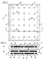
- Fig. 1 shows a schematic plan view of a heat insulating body 1 as a preferred embodiment of the present invention
- Fig. 2 two preferred Layered structures of in Fig. 1 each shown thermal insulation body illustrated in a schematic sectional view.
- the heat-insulating body 1 will be first with reference to Fig. 2a ) and in the present embodiment comprises a molding 10 which is embedded in a heat-insulating cover layer 2 which completely surrounds the molding 10.
- the heat-insulating cover layer 2 is a hard foam, which in the present embodiment consists of expanded polystyrene.
- the molded article 10 may be embedded in any desired manner in the heat-insulating cover layer 2, with foaming of the molded article 10 in the cover layer 2 being preferred with regard to simple production and a good seal.
- the heat-insulating cover layer 2 does not have to take over the major part of the thermal insulation, it should nevertheless have certain heat-insulating properties in order to avoid unnecessary thermal bridges.
- the hard foam used in the present embodiment has, for example, a thermal conductivity of 0.030 W / (mK).
- the molded article 10 has a microporous thermal insulation material 12, which is accommodated in an airtight envelope 14.
- the microporous microdam material in the present embodiment is silica (SiO 2 ), although other suitable microporous materials may be used. It is inventively preferred that the material is designed such that the molding 10 has a thermal conductivity of at most 0.005 W / (mK).
- the negative pressure within the envelope 14 may be, for example, between 50 and 100 mbar.
- the airtight sheath 14 is made of aluminum in the present embodiment, but may be made of any material, such as a metal-plastic composite.
- the molding 10 has three adjacent through holes 16, wherein in the molding accordingly Fig. 1 a plurality of rows of through holes 16 may be provided. These passage openings are also filled in the present embodiment with the material of the heat-insulating cover layer 2, so that there is an excellent bond between the heat-insulating cover layer 2 and the molding 10.
- the through-holes 16 can be used for passing bolts, dowels or the like in order to secure the heat-insulating body 10 according to the invention, for example, to a wall to be insulated.
- the surface of the heat-insulating body according to the invention is provided with a marking which indicates the position of the individual passage openings 16.
- Fig. 2b shows a schematic sectional view of an alternative layer structure of the in Fig. 1 shown heat insulation body 1.
- the heat insulation body 1 comprises two sandwich-shaped moldings 10 which are spaced such that the heat-insulating cover layer 2 extends between the two moldings 10.
- the through holes 16 of in Fig. 2b ) shown offset from one another. If an attachment of the heat insulation body 1 is planned with dowels or the like, it is of course possible that some of the through holes of the two moldings 10 are also arranged in alignment, although in Fig. 2b ) Not shown.
- a plurality of heat-insulating bodies 1 are fastened in a planar manner next to one another on a building section, for example on a wall, a roof or even a floor surface.
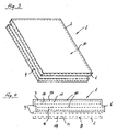
- the in Fig. 2 shown heat insulation body 1 on the opposite edges with mutually complementary profiles 4, 6, which in the in Fig. 2 shown embodiment are formed in the manner of a Jardinnfalzes.
- the profiles 4, 6 are provided on all opposite edges.
- Fig. 4 shows a schematic sectional view of another preferred embodiment of the heat insulation body according to the invention 1.
- the upper part of Fig. 4 which is surrounded by a solid line, in principle, the structure of Fig. 2b ).
- This can be supplemented in the context of the invention by any number of additional moldings 10, which are also coated with a heat-insulating cover layer 2.
- three moldings are combined to form a thermal insulation panel 1 according to the invention, resulting in the arrangement of the moldings 10 and the heat-insulating cover layer 2 profilings 4, 6 in the manner of a tongue and groove arrangement.
Landscapes
- Physics & Mathematics (AREA)
- Engineering & Computer Science (AREA)
- Architecture (AREA)
- Acoustics & Sound (AREA)
- Electromagnetism (AREA)
- Civil Engineering (AREA)
- Structural Engineering (AREA)
- Building Environments (AREA)
- Thermotherapy And Cooling Therapy Devices (AREA)
- Thermal Insulation (AREA)
- Cookers (AREA)
- Secondary Cells (AREA)
Abstract
Description
Die vorliegende Erfindung betrifft einen Wärmedämmkörper, insbesondere Wärmedämmplatte zur Isolierung von Bauwerken, mit mindestens einem Formling, der ein mikroporöses Wärmedämmmaterial aufweist, das in eine luftdichte Umhüllung aufgenommen ist.The present invention relates to a heat-insulating body, in particular heat-insulating panel for the insulation of structures, with at least one molding, which has a microporous thermal insulation material, which is accommodated in an airtight envelope.
Wärmedämmkörper der eingangs genannten Art finden beispielsweise in der Automobilindustrie, im Anlagenbau oder bei Kühlschränken zunehmend Anwendung. So offenbaren beispielsweise die
Derartige Wärmedämmkörper besitzen ausgezeichnete wärmedämmende Eigenschaften, vor allem da durch den vakuumähnlichen Zustand innerhalb der Umhüllung Wärmeleitung infolge Konvektion weitgehend unterbunden ist. Hierdurch lassen sie die Abmessungen und das Gewicht der Wärmedämmung erheblich reduzieren.Such heat insulation body have excellent thermal insulation properties, especially since heat conduction due to convection is largely prevented by the vacuum-like state within the enclosure. As a result, they significantly reduce the dimensions and weight of the thermal insulation.
Allerdings hat sich gezeigt, dass diese Technologie für Anwendungen mit hohen mechanischen Beanspruchungen nur bedingt geeignet ist, da durch Stöße, Schläge etc. leicht eine Beschädigung der luftdichten Umhüllung hervorgerufen werden kann, was zu einem drastischen Absinken der Wärmedämmung führt.However, it has been shown that this technology is only of limited suitability for applications with high mechanical stresses, since damage to the airtight enclosure can easily be caused by impacts, impacts, etc., which leads to a drastic decrease in the thermal insulation.
Ferner offenbart die
Es ist daher Aufgabe der Erfindung, einen Wärmedämmkörper bereitzustellen, der ausgezeichnete Wärmedämmeigenschaften mit einer verbesserten mechanischen Widerstandsfähigkeit verbindet.It is therefore an object of the invention to provide a heat insulating body that combines excellent thermal insulation properties with improved mechanical resistance.
Diese Aufgabe wird erfindungsgemäß durch einen Wärmedämmkörper mit den Merkmalen von Anspruch 1 gelöst. Vorteilhafte Weiterbildungen der Erfindung sind in den abhängigen Ansprüchen angegeben.This object is achieved by a heat-insulating body with the features of
Der Erfindung liegt der Gedanke zugrunde, mindestens einen vakuumisolierten Formling mit einem weiteren wärmedämmenden Material zu kombinieren, das den Formling beispielsweise durch seine Festigkeit, seine Dämpfungseigenschaften, seine Geometrie etc. eine erhöhte mechanische Widerstandsfähigkeit verleiht. Zu diesem Zweck weist der Wärmedämmkörper eine wärmedämmende Deckschicht auf, die den mindestens einen Formling vollständig umgibt. Hierdurch wird es erstmals möglich, vakuumisolierte Wärmedämmkörper auch im Bereich hoher mechanische Beanspruchungen wie beispielsweise bei Fassaden, Dachdeckungen und ähnlichen Anwendungen im Baubereich einzusetzen.The invention is based on the idea to combine at least one vacuum-insulated molding with another heat-insulating material, which gives the molded article, for example, by its strength, its damping properties, its geometry, etc. increased mechanical resistance. For this purpose, the heat insulation body has a heat-insulating cover layer which completely surrounds the at least one molding. This makes it possible for the first time to use vacuum-insulated heat insulation body in the field of high mechanical stresses such as facades, roofing and similar applications in the construction sector.
Insbesondere sorgt die wärmedämmende Deckschicht dafür, dass die Umhüllung der jeweiligen Formlinge nicht bereits bei leichten Schlägen oder Stößen zerstört wird. Gleichzeitig trägt die Deckschicht aufgrund ihrer wärmedämmenden Eigenschaften aber auch zu der gewünschten Wärmedämmung bei, während der Wärmedämmkörper als Ganzes sine kompakten Abmessungen beibehält. Nicht zuletzt verleiht die wärmedämmende Deckschicht dem erfindungsgemäßen Wärmedämmkörper als Ganzes auch strukturelle Stabilität, so dass es beispielsweise möglich wird, den Wärmedämmkörper mit wenigen Befestigungspunkten an einem Tragwerk dauerhaft anzubringen.In particular, the heat-insulating cover ensures that the envelope of the respective moldings is not destroyed even in light bumps or shocks. At the same time, the cover layer, due to its heat-insulating properties, also contributes to the desired thermal insulation, while the heat-insulating body as a whole retains its compact dimensions. Not least, the heat-insulating cover layer gives the heat insulation body according to the invention as a whole also structural stability, so that it is possible, for example, to permanently attach the heat insulation body with a few attachment points on a supporting structure.
Hinsichtlich Anwendungen im Baubereich stellt der erfindungsgemäße Wärmedämmkörper auch eine geeignete Grundlage für weitere Gebäudeschichten dar. So kann auf die wärmedämmende Deckschicht, die beispielsweise aus Hartschaum bestehen kann, problemlos Putz, Estrich, oder dergleichen aufgetragen werden, was auf den glatten Aluminiumhüllen von vakuumisolierten Formlingen nicht sinnvoll ist.With regard to applications in the construction sector, the heat insulation body according to the invention also provides a suitable basis for further building layers. For example, plaster, screed, or the like can be easily applied to the heat-insulating cover layer, which can be made of hard foam, for example, which does not affect the smooth aluminum envelopes of vacuum-insulated molded articles makes sense.
Gemäß der vorliegenden Erfindung weist der mindestens eine Formling mindestens eine Durchgangsöffnung und optional eine Randkerbe auf. Die Durchgangsöffnung und ggf. optionale Randkerbe kann im Rahmen der vorliegenden Erfindung vorteilhaft zwei Aufgaben erfüllen. Einerseits ermöglicht die mindestens eine Durchgangsöffnung und ggl. optionale Randkerbe einen verbesserten Verbund zwischen dem jeweiligen Formling und der wärmedämmenden Deckschicht, was die strukturelle Stabilität des erfindungsgemäßen Wärmedämmkörpers deutlich erhöht. Dabei erstreckt sich das Material der wärmedämmenden Deckschicht in die mindestens eine Durchgangsöffnung.According to the present invention, the at least one molding has at least one passage opening and optionally an edge notch. The passage opening and optionally optional edge notch can advantageously fulfill two tasks in the context of the present invention. On the one hand allows the at least one through hole and ggl. optional edge notch improved bonding between the respective molding and the heat-insulating cover layer, which significantly increases the structural stability of the heat-insulating body according to the invention. In this case, the material of the heat-insulating cover layer extends into the at least one passage opening.
Andererseits kann die mindestens eine Durchgangsöffnung und ggl. optionale Randkerbe auch als Befestigungspunkt für Bolzen, Dübel oder dergleichen verwendet werden, um den Wärmedämmkörper an dem Bauwerk zu befestigen, ohne den mindestens einen Formling des erfindungsgemäßen Wärmedämmkörpers zu beschädigen. Dabei ist jedoch zu beachten, dass der erfindungsgemäße Wärmedämmkörper auch auf andere Art an dem Bauwerk angebracht werden kann, beispielsweise durch Auftragen von Mörtel oder dergleichen.On the other hand, the at least one through hole and ggl. optional edge notch can also be used as an attachment point for bolts, dowels or the like, to attach the heat-insulating body to the structure without damaging the at least one molded article of the heat-insulating body according to the invention. It should be noted, however, that the thermal insulation body according to the invention can also be attached to the building in a different manner, for example by applying mortar or the like.
Gemäß einer Weiterbildung der Erfindung weist die wärmedämmende Deckschicht Hartschaum, bevorzugt expandiertes Polystyrol auf. Auf diese Weise verbindet die wärmedämmende Deckschicht gute wärmedämmende Eigenschaften mit einer ausreichenden mechanischen Festigkeit und Stabilität. Darüber hinaus ergibt sich bei Verwendung von Hartschaum, insbesondere expandiertem Polystyrol, ein einfacher und kostengünstiger Herstellungsprozess, wobei es in diesem Zusammenhang besonders bevorzugt ist, dass der mindestens eine Formling in die Deckschicht eingeschäumt ist.According to one embodiment of the invention, the heat-insulating cover layer hard foam, preferably expanded polystyrene. In this way, the heat-insulating cover layer combines good heat-insulating properties with a sufficient mechanical strength and stability. In addition, when using rigid foam, in particular expanded polystyrene, results in a simple and cost-effective production process, wherein it is particularly preferred in this context that the at least a molding is foamed into the cover layer.
Bei dem mikroporösen Wärmedämmmaterial des mindestens einen Formlings kann es sich grundsätzlich um einen beliebigen geeigneten Stoff handeln. Um zu angemessenen Kosten eine ausgezeichnete Wärmedämmung zu erzielen ist es jedoch erfindungsgemäß bevorzugt, dass das mikroporöse Wärmedämmmaterial Kieselsäure aufweist. Dabei lässt sich die Wärmedämmung des mindestens einen Formlings gemäß einer Weiterbildung der vorliegenden Erfindung auf einfache Weise noch weiter steigern, wenn innerhalb der Umhüllung des mindestens einen Formlings ein Unterdruck herrscht. Obgleich die Erfindung nicht auf einen bestimmten Unterdruck begrenzt ist, hat sich gezeigt, dass Absolutdrücke von höchstens 100 mbar, besonders bevorzugt höchstens 50 mbar ausreichende Wärmedämmeigenschaften bieten und noch wirtschaftlich ausführbar sind.The microporous thermal insulation material of the at least one molding may in principle be any suitable substance. In order to achieve excellent thermal insulation at reasonable cost, however, it is preferred in the invention that the microporous thermal insulation material comprises silica. In this case, the thermal insulation of the at least one molding according to an embodiment of the present invention can be further increased in a simple manner even if there is a negative pressure within the enclosure of the at least one molding. Although the invention is not limited to a specific negative pressure, it has been found that absolute pressures of at most 100 mbar, more preferably at most 50 mbar, provide sufficient thermal insulation properties and are still economically viable.
Der mindestens eine Formling des erfindungsgemäßen Wärmedämmkörpers ist hinsichtlich seiner Abmessungen, insbesondere seiner Dicke, nicht besonders beschränkt. Er sollte jedoch unter Berücksichtigung der verwendeten Materialien derart ausgelegt sein, dass er eine Wärmeleitfähigkeit von höchstens 0,005 W/(mK) besitzt. Alternativ oder zusätzlich ist gemäß einer Weiterbildung der vorliegenden Erfindung vorgesehen, dass die wärmedämmende Deckschicht eine Wärmeleitfähigkeit von höchstens 0,050 W/(mK) aufweist. Durch diese Werte der jeweiligen Wärmeleitfähigkeit lassen sich Wärmedämmkörper insbesondere zur Isolierung von Bauwerken schaffen, die eine deutlich verbesserte Wärmeisolierung bzw. erheblich kompaktere Abmessungen/Dicken ermöglichen.The at least one molded article of the thermal insulation body according to the invention is not particularly limited in terms of its dimensions, in particular its thickness. However, considering the materials used, it should be designed so that it has a thermal conductivity of at most 0.005 W / (mK). Alternatively or additionally, it is provided according to a development of the present invention that the heat-insulating cover layer has a thermal conductivity of at most 0.050 W / (mK). By means of these values of the respective thermal conductivity, it is possible to provide heat-insulating bodies, in particular for the insulation of structures, which enable significantly improved thermal insulation or considerably more compact dimensions / thicknesses.
In einer einfachen Ausführungsform kann der erfindungsgemäße Wärmedämmkörper prinzipiell lediglich einen einzigen Formling aufweisen. Hinsichtlich einer optimierten Wärmedämmung oder auch einer Anpassung an geometrische Anforderungen ist gemäß einer Weiterbildung der vorliegenden Erfindung jedoch vorgesehen, dass er mindestens zwei sandwichartig angeordnete Formlinge aufweist. Dabei ist es besonders bevorzugt, dass sich die wärmedämmende Deckschicht zwischen jeweils benachbarte Formlinge erstreckt.In a simple embodiment, the thermal insulation body according to the invention can in principle have only one single molded article. With regard to an optimized thermal insulation or an adaptation to geometric requirements, however, according to a development of the present invention it is provided that it has at least two sandwich-shaped moldings. It is particularly preferred that the heat-insulating cover layer extends between adjacent moldings.
Gemäß einer Weiterbildung dieses Konzepts mit mindestens zwei sandwichartig angeordneten Formlingen ist vorgesehen, dass zumindest einige Durchgangsöffnungen benachbarter Formlinge versetzt angeordnet sind. Hierdurch wird einerseits eine verbesserte Wärmedämmung erzielt, während andererseits auch ein erhöhter Verbund zwischen benachbarten Formlingen bzw. den Formlingen und der wärmedämmenden Deckschicht erreicht wird.According to a development of this concept with at least two sandwich-shaped moldings it is provided that at least some passage openings of adjacent moldings are arranged offset. As a result, on the one hand, an improved thermal insulation is achieved, while on the other hand, an increased bond between adjacent moldings or the moldings and the heat-insulating cover layer is achieved.
Um die Ausbildung von Wärmebrücken zwischen benachbarten Wärmedämmkörpern am Bauwerk zu vermeiden, ist gemäß einer Weiterbildung der vorliegenden Erfindung vorgesehen, dass der Wärmedämmkörper auf gegenüberliegenden Rändern zueinander komplementäre Profilierungen besitzt, die bevorzugt nach Art eines Stufenfalzes oder einer Nut-Feder-Anordnung ausgebildet sind. Hierdurch lässt sich gleichzeitig eine lagegenaue Positionierung und eine erhöhte Zuverlässigkeit beim Anbringen der Wärmedämmkörper an einem Bauwerk erzielen.In order to avoid the formation of thermal bridges between adjacent heat-insulating bodies on the building, according to a development of the present invention, it is provided that the heat-insulating body has mutually complementary profiles on opposite edges which are preferably designed in the manner of a stepped rebate or a tongue and groove arrangement. As a result, a positionally accurate positioning and increased reliability when attaching the heat-insulating body to a building can be achieved at the same time.
Im Hinblick auf die Nutzung von Durchgangsöffnungen als Befestigungspunkte ist bei Ausführungsformen mit mindestens zwei sandwichartig angeordneten Formlingen ferner bevorzugt, dass zumindest einige Durchgangsöffnungen benachbarter Formlinge im Wesentlichen zueinander fluchtend angeordnet sind. In diesem Falle können Befestigungselemente durch den Wärmedämmkörper hindurchgeführt werden, ohne die Formlinge zu beschädigen. Dabei ist es im Hinblick auf ein einfaches und beschädigungsfreies Setzen der Befestigungselemente bevorzugt, dass die Lage der fluchtenden Durchgangsöffnungen an der Oberfläche des Wärmedämmkörpers erkennbar ist, beispielsweise anhand von Markierungen, Erhöhungen oder dergleichen.With regard to the use of passage openings as fastening points, it is further preferred in embodiments having at least two sandwich-shaped moldings that at least some passage openings of adjacent moldings are arranged substantially in alignment with one another. In this case, fasteners can be passed through the heat-insulating body without damaging the moldings. It is preferred in terms of a simple and damage-free setting of the fasteners that the position of the aligned through holes can be seen on the surface of the heat-insulating body, for example on the basis of markings, elevations or the like.
Die Umhüllung des mindestens einen Formlings kann im Rahmen der vorliegenden Erfindung aus einem geeigneten, luftdichten Material bestehen. Im Hinblick auf eine einfache Herstellung und eine hohe Dauerhaftigkeit des erfindungsgemäßen Wärmedämmkörpers ist es jedoch bevorzugt, dass die Umhüllung des mindestens einen Formlings aus Aluminium oder Kunststoff besteht.The envelope of the at least one molding may in the context of the present invention consist of a suitable airtight material. However, in view of a simple production and a high durability of the thermal insulation body according to the invention, it is preferred that the envelope of the at least one molding is made of aluminum or plastic.
- Fig. 1Fig. 1
-
zeigt eine schematische Draufsicht eines Wärmedämmkörpers 1 als bevorzugte Ausführungsform der vorliegenden Erfindung;shows a schematic plan view of a
heat insulating body 1 as a preferred embodiment of the present invention; - Fig. 2Fig. 2
-
zeigt jeweils in einer schematischen Schnittansicht zwei bevorzugte Schichtaufbauten des Wärmedämmkörpers aus
Fig. 1 , wobei der Schnitt jeweils entlang der Linie A-A inFig. 1 geführt ist;shows in a schematic sectional view of two preferred layer structures of the heat-insulating bodyFig. 1 , wherein the section respectively along the line AA inFig. 1 is guided; - Fig. 3Fig. 3
-
zeigt eine schematische Perspektivansicht des Wärmedämmkörpers gemäß
Fig. 2a );shows a schematic perspective view of the heat-insulating body according toFig. 2a ); - Fig. 4Fig. 4
- zeigt eine schematische Schnittansicht einer weiteren Ausführungsform des erfindungsgemäßen Wärmedämmkörpers.shows a schematic sectional view of another embodiment of the heat-insulating body according to the invention.
Bevorzugte Ausführungsformen der vorliegenden Erfindung werden nachfolgend unter Bezugnahme auf die begleitenden Zeichnungen beschrieben.Preferred embodiments of the present invention will be described below with reference to the accompanying drawings.
Obgleich die wärmedämmende Deckschicht 2 nicht den Hauptanteil der Wärmedämmung übernehmen muss, sollte sie doch gewisse wärmedämmende Eigenschaften besitzen, um unnötige Wärmebrücken zu vermeiden. Der in der vorliegenden Ausführungsform verwendete Hartschaum besitzt beispielsweise eine Wärmeleitfähigkeit von 0,030 W/(mK).Although the heat-insulating
Der Formling 10 weist ein mikroporöses Wärmedämmmaterial 12 auf, das in eine luftdichte Umhüllung 14 aufgenommen ist. Bei dem mikroporösen Mikrodämmmaterial handelt es sich bei der vorliegenden Ausführungsform um Kieselsäure (SiO2), wobei jedoch auch andere geeignete, mikroporöse Stoffe zum Einsatz kommen können. Dabei ist es erfindungsgemäß bevorzugt, dass das Material derart ausgelegt ist, dass der Formling 10 eine Wärmeleitfähigkeit von höchstens 0,005 W/(mK) besitzt. Darüber hinaus herrscht innerhalb der Umhüllung 14 des Formlings 10 ein Unterdruck. Dieser sollte erfindungsgemäß derart festgelegt werden, dass sich ein guter Kompromiss aus einer wirtschaftlichen Herstellung und ausgezeichneten Wärmedämmeigenschaften des Formlings 10 ergibt. Zu diesem Zweck kann der Unterdruck innerhalb der Umhüllung 14 beispielsweise zwischen 50 und 100 mbar liegen.The molded
Die luftdichte Umhüllung 14 besteht in der vorliegenden Ausführungsform aus Aluminium, kann jedoch aus einem beliebigen Material besteht, beispielsweise einem Metall-Kunststoffverbund.The
Wie in
In praktischen Anwendungen werden erfindungsgemäß mehrere Wärmedämmkörper 1 flächig nebeneinanderliegend an einem Bauwerksabschnitt befestigt, beispielsweise an einer Wand, einem Dach oder auch einer Bodenfläche. Um hierbei ein einfaches Positionieren zu erzielen und die Ausbildung von Wärmebrücken im Stoßfugenbereich zu verhindern, sind die in
Claims (11)
- Thermal insulation member (1) for insulating building structures, in particular a thermal insulation panel, having at least one moulding (10) comprising a microporous thermal insulation material (12) accommodated in an airtight envelope (14),
Wherein the thermal insulation member (1) further comprises a thermally insulating covering layer (2) completely surrounding the at least single moulding (10),
Characterised in that the at least single moulding (10) has at least one through-opening (16), and
The at least single through-opening (16) of the moulding is filled in with the material of the thermally insulating covering layer (2). - Thermal insulation member according to claim 1, characterised in that the thermally insulating covering layer (2) comprises rigid foam, preferably expanded polystyrene, wherein the at least single moulding (10) is particularly preferably foam-embedded into the covering layer (2).
- Thermal insulation member according to claim 1 or 2, characterised in that the microporous thermal insulation material (12) comprises silicic acid (SiO2) or similar substances.
- Thermal insulation member according to any of the preceding claims, characterised in that within the envelope (14) of the at least single moulding (10) a partial vacuum prevails.
- Thermal insulation member according to any of the preceding claims, characterised in that the at least single moulding (10) has a thermal conductivity of at most 0.005 W/(mk) and/or the thermally insulating covering layer (2) has a thermal conductivity of at most 0.050 W/(mk).
- Thermal insulation member according to any of the preceding claims, characterised in that it comprises at least two mouldings (10) arranged in sandwich-like manner, wherein the thermally insulating covering layer (2) preferably extends between mouldings adjoining one another.
- Thermal insulation member according to any of the preceding claims, characterised in that it comprises at least two mouldings (10), arranged in sandwich-like manner, wherein at least some through-openings (16) of adjoining mouldings are arranged in offset manner.
- Thermal insulation member according to any of the preceding claims, characterised in that it comprises at least two mouldings arranged in sandwich-like manner, wherein at least some through-openings of adjoining mouldings are arranged substantially in alignment with one another.
- Thermal insulation member according to claim 8, characterised in that the position of the aligned through-openings is discernable on the surface of the thermal insulation member.
- Thermal insulation member according to any of the preceding claims, characterised in that the envelope (14) of the at least single moulding (10) consists of aluminium or plastic.
- Thermal insulation member according to any of the preceding claims, characterised in that it possesses shaped profiles (4, 6) complementary to one another at opposite edges, preferably in the manner of a stepped rebate or tongue-and-groove arrangement.
Priority Applications (5)
| Application Number | Priority Date | Filing Date | Title |
|---|---|---|---|
| AT04003612T ATE363382T1 (en) | 2004-02-18 | 2004-02-18 | HEAT INSULATION BODY |
| DK04003612.1T DK1566264T4 (en) | 2004-02-18 | 2004-02-18 | Heat insulating body |
| SI200430407T SI1566264T2 (en) | 2004-02-18 | 2004-02-18 | Heat insulating panel |
| DE502004003939T DE502004003939D1 (en) | 2004-02-18 | 2004-02-18 | heat insulation body |
| EP04003612A EP1566264B2 (en) | 2004-02-18 | 2004-02-18 | Heat insulating panel |
Applications Claiming Priority (1)
| Application Number | Priority Date | Filing Date | Title |
|---|---|---|---|
| EP04003612A EP1566264B2 (en) | 2004-02-18 | 2004-02-18 | Heat insulating panel |
Publications (3)
| Publication Number | Publication Date |
|---|---|
| EP1566264A1 EP1566264A1 (en) | 2005-08-24 |
| EP1566264B1 EP1566264B1 (en) | 2007-05-30 |
| EP1566264B2 true EP1566264B2 (en) | 2011-11-23 |
Family
ID=34707305
Family Applications (1)
| Application Number | Title | Priority Date | Filing Date |
|---|---|---|---|
| EP04003612A Expired - Lifetime EP1566264B2 (en) | 2004-02-18 | 2004-02-18 | Heat insulating panel |
Country Status (5)
| Country | Link |
|---|---|
| EP (1) | EP1566264B2 (en) |
| AT (1) | ATE363382T1 (en) |
| DE (1) | DE502004003939D1 (en) |
| DK (1) | DK1566264T4 (en) |
| SI (1) | SI1566264T2 (en) |
Cited By (2)
| Publication number | Priority date | Publication date | Assignee | Title |
|---|---|---|---|---|
| DE202012105100U1 (en) | 2011-12-31 | 2013-04-22 | Ideefa Gmbh & Co. Kg | Functional ventilation facade with ventilation ducts |
| DE202012105099U1 (en) | 2011-12-31 | 2013-04-22 | Ideefa Gmbh & Co. Kg | Functional ventilation facade |
Families Citing this family (7)
| Publication number | Priority date | Publication date | Assignee | Title |
|---|---|---|---|---|
| DE202008012675U1 (en) * | 2008-09-24 | 2009-01-02 | SCHWENK DÄMMTECHNIK GMBH & Co KG | Insulating element and use of an insulating element |
| DE102008064572A1 (en) * | 2008-12-30 | 2010-07-08 | Alsecco Gmbh & Co Kg | Multilayered thermal insulation board and method for building a thermal insulation facade |
| DK2210991T3 (en) | 2009-01-21 | 2016-02-22 | Kingspan Insulation B V | external vægisolationssystem |
| FR2945557B1 (en) | 2009-05-12 | 2011-07-08 | Electricite De France | IMPROVED INSULATING FLOOR. |
| DE102009060401A1 (en) * | 2009-12-22 | 2011-07-07 | Fraunhofer-Gesellschaft zur Förderung der angewandten Forschung e.V., 80686 | Component and method for operating a photovoltaic module |
| DE202010005403U1 (en) | 2010-05-07 | 2010-08-26 | Friedrich, Jessica | Training and arrangement of insulating panels for facades, ceilings, walls or roofs |
| DE102010044789A1 (en) * | 2010-09-09 | 2012-03-15 | Calsitherm Verwaltungs Gmbh | Thermal insulation plate for masonry wall, has chambers arranged between cover layer plate and barrier layer, where barrier layer is provided as barrier layer plate |
Citations (4)
| Publication number | Priority date | Publication date | Assignee | Title |
|---|---|---|---|---|
| DE4331590C1 (en) † | 1993-09-17 | 1994-08-11 | Porextherm Daemmstoffe Gmbh | Pressed insulating composite moulding |
| JPH08303686A (en) † | 1995-04-28 | 1996-11-22 | Mitsubishi Chem Corp | Vacuum insulation panel and manufacturing method thereof |
| WO2004001149A2 (en) † | 2002-06-24 | 2003-12-31 | Sager Ag | Vacuum insulation panel, method for the heat insulation of objects and auxiliary agent therefor |
| DE10234409A1 (en) † | 2002-07-29 | 2004-02-12 | Va-Q-Tec Ag | Film-encased vacuum insulation panel has indentations on one or more edge sections, each indentation having shape of ellipse or circle segment, and edge of insulating panel extends parallel to longitudinal axis of ellipse |
Family Cites Families (9)
| Publication number | Priority date | Publication date | Assignee | Title |
|---|---|---|---|---|
| JPS5796852A (en) * | 1980-12-09 | 1982-06-16 | Matsushita Electric Industrial Co Ltd | Heat insulating material |
| US4492725A (en) * | 1982-07-20 | 1985-01-08 | Matsushita Electric Industrial Co., Ltd. | Composite thermal insulator |
| DE3418637A1 (en) * | 1984-05-18 | 1985-11-21 | Wacker-Chemie GmbH, 8000 München | THERMAL INSULATION BODY WITH COVER |
| DE4344713A1 (en) * | 1993-12-27 | 1995-03-09 | Aabh Patent Holdings | Double-walled thermal insulation |
| US5681639A (en) * | 1994-09-21 | 1997-10-28 | Revall Co., Ltd. | Waterproof lightweight grain-tone decorative panel |
| DE29605338U1 (en) * | 1996-03-22 | 1997-07-17 | Bayer Ag, 51373 Leverkusen | Vacuum insulation panel coated on both sides with aluminum-containing composite film |
| HRP970104A2 (en) * | 1996-03-22 | 1998-02-28 | Bayer Ag | Vacuum insulating panels wraped on both sides by a foil containing metal or by a metal covering layer |
| DE19809316C2 (en) * | 1998-03-05 | 2000-11-09 | Plus Recycling Gmbh R | Heat insulation body and multilayer body therefor |
| WO2003002828A1 (en) * | 2001-06-29 | 2003-01-09 | Sager Ag | Vacuum insulation panel |
-
2004
- 2004-02-18 AT AT04003612T patent/ATE363382T1/en active
- 2004-02-18 DK DK04003612.1T patent/DK1566264T4/en active
- 2004-02-18 DE DE502004003939T patent/DE502004003939D1/en not_active Expired - Lifetime
- 2004-02-18 SI SI200430407T patent/SI1566264T2/en unknown
- 2004-02-18 EP EP04003612A patent/EP1566264B2/en not_active Expired - Lifetime
Patent Citations (4)
| Publication number | Priority date | Publication date | Assignee | Title |
|---|---|---|---|---|
| DE4331590C1 (en) † | 1993-09-17 | 1994-08-11 | Porextherm Daemmstoffe Gmbh | Pressed insulating composite moulding |
| JPH08303686A (en) † | 1995-04-28 | 1996-11-22 | Mitsubishi Chem Corp | Vacuum insulation panel and manufacturing method thereof |
| WO2004001149A2 (en) † | 2002-06-24 | 2003-12-31 | Sager Ag | Vacuum insulation panel, method for the heat insulation of objects and auxiliary agent therefor |
| DE10234409A1 (en) † | 2002-07-29 | 2004-02-12 | Va-Q-Tec Ag | Film-encased vacuum insulation panel has indentations on one or more edge sections, each indentation having shape of ellipse or circle segment, and edge of insulating panel extends parallel to longitudinal axis of ellipse |
Cited By (2)
| Publication number | Priority date | Publication date | Assignee | Title |
|---|---|---|---|---|
| DE202012105100U1 (en) | 2011-12-31 | 2013-04-22 | Ideefa Gmbh & Co. Kg | Functional ventilation facade with ventilation ducts |
| DE202012105099U1 (en) | 2011-12-31 | 2013-04-22 | Ideefa Gmbh & Co. Kg | Functional ventilation facade |
Also Published As
| Publication number | Publication date |
|---|---|
| DK1566264T4 (en) | 2011-12-19 |
| SI1566264T1 (en) | 2007-10-31 |
| DE502004003939D1 (en) | 2007-07-12 |
| SI1566264T2 (en) | 2012-03-30 |
| ATE363382T1 (en) | 2007-06-15 |
| EP1566264B1 (en) | 2007-05-30 |
| EP1566264A1 (en) | 2005-08-24 |
| DK1566264T3 (en) | 2007-09-24 |
Similar Documents
| Publication | Publication Date | Title |
|---|---|---|
| EP2666625B1 (en) | Wall construction and thermal insulation panel | |
| EP3350383B1 (en) | Insulation panel and insulation arrangement | |
| EP2216454A2 (en) | Dampening system | |
| EP2726680B1 (en) | Façade construction for thermally insulating and cladding external walls of buildings, and method for producing such a façade construction | |
| EP1566264B2 (en) | Heat insulating panel | |
| DE202009008493U1 (en) | Wall construction and thermal insulation board | |
| WO2016091244A2 (en) | Panel system for creating rooms | |
| DE19516098B4 (en) | Ceiling edge formwork element and method and apparatus for its production | |
| EP2093340A1 (en) | Compound heat insulation board and heat insulation compound system | |
| DE102011053499A1 (en) | Heat insulation composite device for insulating exterior wall of building, has straps arranged between bars in receiving area, where base body comprises specific amount of bulk density and straps comprise specific mm of support width | |
| EP2508692B1 (en) | Insulation board and method for producing same | |
| DE4301565A1 (en) | Lightweight structural element | |
| WO2013017622A1 (en) | Multi-layer component | |
| AT509157A1 (en) | COMPOSITE ELEMENT | |
| DE1084009B (en) | Composite panel | |
| AT409986B (en) | A multilayer front shell | |
| EP3212856B1 (en) | Method to produce a composite heat insulation system | |
| DE3021537A1 (en) | Thermal insulation for tall or underground buildings - esp. where profiled polymer sheet forms air cushion between two aluminium sheets or foils | |
| DE1534738A1 (en) | Insulating plate | |
| DE202019100960U1 (en) | Anchor element for the production of a molded facade, shaped facade | |
| EP3034711B1 (en) | Ceilings edge formwork element | |
| DE9209698U1 (en) | Composite formwork | |
| EP0834625A1 (en) | Composite element and method of making the same | |
| AT13905U1 (en) | Wall element, façade element and facade with a vacuum insulation panel | |
| BE1023265B1 (en) | Insulating facade panel |
Legal Events
| Date | Code | Title | Description |
|---|---|---|---|
| PUAI | Public reference made under article 153(3) epc to a published international application that has entered the european phase |
Free format text: ORIGINAL CODE: 0009012 |
|
| AK | Designated contracting states |
Kind code of ref document: A1 Designated state(s): AT BE BG CH CY CZ DE DK EE ES FI FR GB GR HU IE IT LI LU MC NL PT RO SE SI SK TR |
|
| AX | Request for extension of the european patent |
Extension state: AL LT LV MK |
|
| 17P | Request for examination filed |
Effective date: 20060124 |
|
| AKX | Designation fees paid |
Designated state(s): AT BE BG CH CY CZ DE DK EE ES FI FR GB GR HU IE IT LI LU MC NL PT RO SE SI SK TR |
|
| GRAP | Despatch of communication of intention to grant a patent |
Free format text: ORIGINAL CODE: EPIDOSNIGR1 |
|
| GRAS | Grant fee paid |
Free format text: ORIGINAL CODE: EPIDOSNIGR3 |
|
| GRAA | (expected) grant |
Free format text: ORIGINAL CODE: 0009210 |
|
| AK | Designated contracting states |
Kind code of ref document: B1 Designated state(s): AT BE BG CH CY CZ DE DK EE ES FI FR GB GR HU IE IT LI LU MC NL PT RO SE SI SK TR |
|
| PG25 | Lapsed in a contracting state [announced via postgrant information from national office to epo] |
Ref country code: FI Free format text: LAPSE BECAUSE OF FAILURE TO SUBMIT A TRANSLATION OF THE DESCRIPTION OR TO PAY THE FEE WITHIN THE PRESCRIBED TIME-LIMIT Effective date: 20070530 |
|
| REG | Reference to a national code |
Ref country code: GB Ref legal event code: FG4D Free format text: NOT ENGLISH |
|
| GBT | Gb: translation of ep patent filed (gb section 77(6)(a)/1977) |
Effective date: 20070605 |
|
| REG | Reference to a national code |
Ref country code: CH Ref legal event code: EP |
|
| REG | Reference to a national code |
Ref country code: IE Ref legal event code: FG4D Free format text: LANGUAGE OF EP DOCUMENT: GERMAN |
|
| REF | Corresponds to: |
Ref document number: 502004003939 Country of ref document: DE Date of ref document: 20070712 Kind code of ref document: P |
|
| REG | Reference to a national code |
Ref country code: CH Ref legal event code: NV Representative=s name: NOVAGRAAF INTERNATIONAL SA |
|
| REG | Reference to a national code |
Ref country code: RO Ref legal event code: EPE |
|
| PG25 | Lapsed in a contracting state [announced via postgrant information from national office to epo] |
Ref country code: ES Free format text: LAPSE BECAUSE OF FAILURE TO SUBMIT A TRANSLATION OF THE DESCRIPTION OR TO PAY THE FEE WITHIN THE PRESCRIBED TIME-LIMIT Effective date: 20070910 |
|
| REG | Reference to a national code |
Ref country code: SE Ref legal event code: TRGR |
|
| REG | Reference to a national code |
Ref country code: GR Ref legal event code: EP Ref document number: 20070402642 Country of ref document: GR |
|
| ET | Fr: translation filed | ||
| REG | Reference to a national code |
Ref country code: IE Ref legal event code: FD4D |
|
| PG25 | Lapsed in a contracting state [announced via postgrant information from national office to epo] |
Ref country code: PT Free format text: LAPSE BECAUSE OF FAILURE TO SUBMIT A TRANSLATION OF THE DESCRIPTION OR TO PAY THE FEE WITHIN THE PRESCRIBED TIME-LIMIT Effective date: 20071030 Ref country code: BG Free format text: LAPSE BECAUSE OF FAILURE TO SUBMIT A TRANSLATION OF THE DESCRIPTION OR TO PAY THE FEE WITHIN THE PRESCRIBED TIME-LIMIT Effective date: 20070830 Ref country code: IE Free format text: LAPSE BECAUSE OF FAILURE TO SUBMIT A TRANSLATION OF THE DESCRIPTION OR TO PAY THE FEE WITHIN THE PRESCRIBED TIME-LIMIT Effective date: 20070530 |
|
| PG25 | Lapsed in a contracting state [announced via postgrant information from national office to epo] |
Ref country code: SK Free format text: LAPSE BECAUSE OF FAILURE TO SUBMIT A TRANSLATION OF THE DESCRIPTION OR TO PAY THE FEE WITHIN THE PRESCRIBED TIME-LIMIT Effective date: 20070530 |
|
| PLBI | Opposition filed |
Free format text: ORIGINAL CODE: 0009260 |
|
| 26 | Opposition filed |
Opponent name: VARIOTEC SANDWICHELEMENTE GMBH & CO. KG Effective date: 20080221 |
|
| PLAX | Notice of opposition and request to file observation + time limit sent |
Free format text: ORIGINAL CODE: EPIDOSNOBS2 |
|
| PG25 | Lapsed in a contracting state [announced via postgrant information from national office to epo] |
Ref country code: IT Free format text: LAPSE BECAUSE OF FAILURE TO SUBMIT A TRANSLATION OF THE DESCRIPTION OR TO PAY THE FEE WITHIN THE PRESCRIBED TIME-LIMIT Effective date: 20070530 |
|
| NLR1 | Nl: opposition has been filed with the epo |
Opponent name: VARIOTEC SANDWICHELEMENTE GMBH & CO. KG |
|
| REG | Reference to a national code |
Ref country code: HU Ref legal event code: AG4A Ref document number: E002946 Country of ref document: HU |
|
| PLBB | Reply of patent proprietor to notice(s) of opposition received |
Free format text: ORIGINAL CODE: EPIDOSNOBS3 |
|
| PG25 | Lapsed in a contracting state [announced via postgrant information from national office to epo] |
Ref country code: MC Free format text: LAPSE BECAUSE OF NON-PAYMENT OF DUE FEES Effective date: 20080228 |
|
| PG25 | Lapsed in a contracting state [announced via postgrant information from national office to epo] |
Ref country code: EE Free format text: LAPSE BECAUSE OF FAILURE TO SUBMIT A TRANSLATION OF THE DESCRIPTION OR TO PAY THE FEE WITHIN THE PRESCRIBED TIME-LIMIT Effective date: 20070530 |
|
| PG25 | Lapsed in a contracting state [announced via postgrant information from national office to epo] |
Ref country code: CY Free format text: LAPSE BECAUSE OF FAILURE TO SUBMIT A TRANSLATION OF THE DESCRIPTION OR TO PAY THE FEE WITHIN THE PRESCRIBED TIME-LIMIT Effective date: 20070530 |
|
| PLAB | Opposition data, opponent's data or that of the opponent's representative modified |
Free format text: ORIGINAL CODE: 0009299OPPO |
|
| PG25 | Lapsed in a contracting state [announced via postgrant information from national office to epo] |
Ref country code: LU Free format text: LAPSE BECAUSE OF NON-PAYMENT OF DUE FEES Effective date: 20080218 |
|
| PG25 | Lapsed in a contracting state [announced via postgrant information from national office to epo] |
Ref country code: TR Free format text: LAPSE BECAUSE OF FAILURE TO SUBMIT A TRANSLATION OF THE DESCRIPTION OR TO PAY THE FEE WITHIN THE PRESCRIBED TIME-LIMIT Effective date: 20070530 |
|
| REG | Reference to a national code |
Ref country code: CH Ref legal event code: PFA Owner name: SCHWENK DAEMMTECHNIK GMBH & CO KG Free format text: SCHWENK DAEMMTECHNIK GMBH & CO KG#ISOTEXSTRASSE 1#D-86899 LANDSBERG (DE) -TRANSFER TO- SCHWENK DAEMMTECHNIK GMBH & CO KG#ISOTEXSTRASSE 1#D-86899 LANDSBERG (DE) |
|
| PUAH | Patent maintained in amended form |
Free format text: ORIGINAL CODE: 0009272 |
|
| STAA | Information on the status of an ep patent application or granted ep patent |
Free format text: STATUS: PATENT MAINTAINED AS AMENDED |
|
| 27A | Patent maintained in amended form |
Effective date: 20111123 |
|
| AK | Designated contracting states |
Kind code of ref document: B2 Designated state(s): AT BE BG CH CY CZ DE DK EE ES FI FR GB GR HU IE IT LI LU MC NL PT RO SE SI SK TR |
|
| REG | Reference to a national code |
Ref country code: DE Ref legal event code: R102 Ref document number: 502004003939 Country of ref document: DE |
|
| REG | Reference to a national code |
Ref country code: CH Ref legal event code: AEN Free format text: AUFRECHTERHALTUNG DES PATENTES IN GEAENDERTER FORM |
|
| REG | Reference to a national code |
Ref country code: NL Ref legal event code: T3 |
|
| REG | Reference to a national code |
Ref country code: DK Ref legal event code: T4 |
|
| REG | Reference to a national code |
Ref country code: SE Ref legal event code: RPEO |
|
| REG | Reference to a national code |
Ref country code: DE Ref legal event code: R102 Ref document number: 502004003939 Country of ref document: DE Effective date: 20111123 |
|
| REG | Reference to a national code |
Ref country code: GR Ref legal event code: EP Ref document number: 20120400060 Country of ref document: GR Effective date: 20120305 |
|
| REG | Reference to a national code |
Ref country code: DE Ref legal event code: R082 Ref document number: 502004003939 Country of ref document: DE Representative=s name: CLAUS-PETER FAUL UND KOLLEGEN, DE |
|
| PGFP | Annual fee paid to national office [announced via postgrant information from national office to epo] |
Ref country code: GB Payment date: 20130128 Year of fee payment: 10 Ref country code: FR Payment date: 20130227 Year of fee payment: 10 Ref country code: DK Payment date: 20130206 Year of fee payment: 10 Ref country code: SE Payment date: 20130214 Year of fee payment: 10 Ref country code: CH Payment date: 20130207 Year of fee payment: 10 Ref country code: RO Payment date: 20130214 Year of fee payment: 10 Ref country code: CZ Payment date: 20130301 Year of fee payment: 10 |
|
| REG | Reference to a national code |
Ref country code: DE Ref legal event code: R081 Ref document number: 502004003939 Country of ref document: DE Owner name: BACHL DAEMMTECHNIK GMBH & CO. KG, DE Free format text: FORMER OWNER: SCHWENK DAEMMTECHNIK GMBH & CO KG, 86899 LANDSBERG, DE Effective date: 20130313 Ref country code: DE Ref legal event code: R082 Ref document number: 502004003939 Country of ref document: DE Representative=s name: CLAUS-PETER FAUL UND KOLLEGEN, DE Effective date: 20130313 |
|
| PGFP | Annual fee paid to national office [announced via postgrant information from national office to epo] |
Ref country code: BE Payment date: 20130207 Year of fee payment: 10 Ref country code: SI Payment date: 20121224 Year of fee payment: 10 Ref country code: NL Payment date: 20130206 Year of fee payment: 10 Ref country code: GR Payment date: 20130227 Year of fee payment: 10 |
|
| PGFP | Annual fee paid to national office [announced via postgrant information from national office to epo] |
Ref country code: AT Payment date: 20130211 Year of fee payment: 10 |
|
| PGFP | Annual fee paid to national office [announced via postgrant information from national office to epo] |
Ref country code: HU Payment date: 20130423 Year of fee payment: 10 |
|
| BERE | Be: lapsed |
Owner name: SCHWENK DAMMTECHNIK G.M.B.H. & CO KG Effective date: 20140228 |
|
| REG | Reference to a national code |
Ref country code: NL Ref legal event code: V1 Effective date: 20140901 |
|
| REG | Reference to a national code |
Ref country code: DK Ref legal event code: EBP Effective date: 20140228 |
|
| REG | Reference to a national code |
Ref country code: CH Ref legal event code: PL Ref country code: SE Ref legal event code: EUG |
|
| REG | Reference to a national code |
Ref country code: AT Ref legal event code: MM01 Ref document number: 363382 Country of ref document: AT Kind code of ref document: T Effective date: 20140218 |
|
| REG | Reference to a national code |
Ref country code: GR Ref legal event code: ML Ref document number: 20120400060 Country of ref document: GR Effective date: 20140903 |
|
| GBPC | Gb: european patent ceased through non-payment of renewal fee |
Effective date: 20140218 |
|
| PG25 | Lapsed in a contracting state [announced via postgrant information from national office to epo] |
Ref country code: LI Free format text: LAPSE BECAUSE OF NON-PAYMENT OF DUE FEES Effective date: 20140228 Ref country code: CH Free format text: LAPSE BECAUSE OF NON-PAYMENT OF DUE FEES Effective date: 20140228 Ref country code: RO Free format text: LAPSE BECAUSE OF NON-PAYMENT OF DUE FEES Effective date: 20140218 Ref country code: NL Free format text: LAPSE BECAUSE OF NON-PAYMENT OF DUE FEES Effective date: 20140901 Ref country code: CZ Free format text: LAPSE BECAUSE OF NON-PAYMENT OF DUE FEES Effective date: 20140218 Ref country code: GR Free format text: LAPSE BECAUSE OF NON-PAYMENT OF DUE FEES Effective date: 20140903 |
|
| REG | Reference to a national code |
Ref country code: FR Ref legal event code: ST Effective date: 20141031 |
|
| PG25 | Lapsed in a contracting state [announced via postgrant information from national office to epo] |
Ref country code: SE Free format text: LAPSE BECAUSE OF NON-PAYMENT OF DUE FEES Effective date: 20140219 Ref country code: SI Free format text: LAPSE BECAUSE OF NON-PAYMENT OF DUE FEES Effective date: 20140219 Ref country code: HU Free format text: LAPSE BECAUSE OF NON-PAYMENT OF DUE FEES Effective date: 20140219 Ref country code: AT Free format text: LAPSE BECAUSE OF NON-PAYMENT OF DUE FEES Effective date: 20140218 |
|
| REG | Reference to a national code |
Ref country code: SI Ref legal event code: KO00 Effective date: 20141007 |
|
| PG25 | Lapsed in a contracting state [announced via postgrant information from national office to epo] |
Ref country code: BE Free format text: LAPSE BECAUSE OF NON-PAYMENT OF DUE FEES Effective date: 20140228 Ref country code: FR Free format text: LAPSE BECAUSE OF NON-PAYMENT OF DUE FEES Effective date: 20140228 Ref country code: GB Free format text: LAPSE BECAUSE OF NON-PAYMENT OF DUE FEES Effective date: 20140218 Ref country code: DK Free format text: LAPSE BECAUSE OF NON-PAYMENT OF DUE FEES Effective date: 20140228 |
|
| PGFP | Annual fee paid to national office [announced via postgrant information from national office to epo] |
Ref country code: DE Payment date: 20230216 Year of fee payment: 20 |
|
| REG | Reference to a national code |
Ref country code: DE Ref legal event code: R071 Ref document number: 502004003939 Country of ref document: DE |