EP1566264B2 - Corps thermo-isolant - Google Patents
Corps thermo-isolant Download PDFInfo
- Publication number
- EP1566264B2 EP1566264B2 EP04003612A EP04003612A EP1566264B2 EP 1566264 B2 EP1566264 B2 EP 1566264B2 EP 04003612 A EP04003612 A EP 04003612A EP 04003612 A EP04003612 A EP 04003612A EP 1566264 B2 EP1566264 B2 EP 1566264B2
- Authority
- EP
- European Patent Office
- Prior art keywords
- thermal insulation
- insulation member
- member according
- heat
- mouldings
- Prior art date
- Legal status (The legal status is an assumption and is not a legal conclusion. Google has not performed a legal analysis and makes no representation as to the accuracy of the status listed.)
- Expired - Lifetime
Links
- 238000009413 insulation Methods 0.000 claims abstract description 53
- 238000000465 moulding Methods 0.000 claims abstract description 51
- 239000012774 insulation material Substances 0.000 claims abstract description 7
- 239000000463 material Substances 0.000 claims description 8
- VYPSYNLAJGMNEJ-UHFFFAOYSA-N Silicium dioxide Chemical compound O=[Si]=O VYPSYNLAJGMNEJ-UHFFFAOYSA-N 0.000 claims description 7
- 239000006260 foam Substances 0.000 claims description 6
- XAGFODPZIPBFFR-UHFFFAOYSA-N aluminium Chemical compound [Al] XAGFODPZIPBFFR-UHFFFAOYSA-N 0.000 claims description 5
- 229910052782 aluminium Inorganic materials 0.000 claims description 5
- 239000004794 expanded polystyrene Substances 0.000 claims description 4
- 230000000295 complement effect Effects 0.000 claims description 3
- 239000004033 plastic Substances 0.000 claims description 3
- 239000000377 silicon dioxide Substances 0.000 claims description 3
- 239000000126 substance Substances 0.000 claims description 2
- 239000004411 aluminium Substances 0.000 claims 1
- 229910052681 coesite Inorganic materials 0.000 claims 1
- 229910052906 cristobalite Inorganic materials 0.000 claims 1
- RMAQACBXLXPBSY-UHFFFAOYSA-N silicic acid Chemical compound O[Si](O)(O)O RMAQACBXLXPBSY-UHFFFAOYSA-N 0.000 claims 1
- 235000012239 silicon dioxide Nutrition 0.000 claims 1
- 229910052682 stishovite Inorganic materials 0.000 claims 1
- 229910052905 tridymite Inorganic materials 0.000 claims 1
- 238000011161 development Methods 0.000 description 5
- 230000018109 developmental process Effects 0.000 description 5
- 238000004519 manufacturing process Methods 0.000 description 4
- 238000010276 construction Methods 0.000 description 3
- 230000015572 biosynthetic process Effects 0.000 description 2
- 230000006978 adaptation Effects 0.000 description 1
- 239000002131 composite material Substances 0.000 description 1
- 238000013016 damping Methods 0.000 description 1
- 230000001419 dependent effect Effects 0.000 description 1
- 238000005516 engineering process Methods 0.000 description 1
- 238000005187 foaming Methods 0.000 description 1
- 239000011888 foil Substances 0.000 description 1
- 239000011810 insulating material Substances 0.000 description 1
- 210000001503 joint Anatomy 0.000 description 1
- 239000012229 microporous material Substances 0.000 description 1
- 239000004570 mortar (masonry) Substances 0.000 description 1
- 239000011505 plaster Substances 0.000 description 1
- 230000035939 shock Effects 0.000 description 1
Images
Classifications
-
- B—PERFORMING OPERATIONS; TRANSPORTING
- B32—LAYERED PRODUCTS
- B32B—LAYERED PRODUCTS, i.e. PRODUCTS BUILT-UP OF STRATA OF FLAT OR NON-FLAT, e.g. CELLULAR OR HONEYCOMB, FORM
- B32B5/00—Layered products characterised by the non- homogeneity or physical structure, i.e. comprising a fibrous, filamentary, particulate or foam layer; Layered products characterised by having a layer differing constitutionally or physically in different parts
- B32B5/18—Layered products characterised by the non- homogeneity or physical structure, i.e. comprising a fibrous, filamentary, particulate or foam layer; Layered products characterised by having a layer differing constitutionally or physically in different parts characterised by features of a layer of foamed material
-
- B—PERFORMING OPERATIONS; TRANSPORTING
- B32—LAYERED PRODUCTS
- B32B—LAYERED PRODUCTS, i.e. PRODUCTS BUILT-UP OF STRATA OF FLAT OR NON-FLAT, e.g. CELLULAR OR HONEYCOMB, FORM
- B32B3/00—Layered products comprising a layer with external or internal discontinuities or unevennesses, or a layer of non-planar shape; Layered products comprising a layer having particular features of form
- B32B3/02—Layered products comprising a layer with external or internal discontinuities or unevennesses, or a layer of non-planar shape; Layered products comprising a layer having particular features of form characterised by features of form at particular places, e.g. in edge regions
- B32B3/06—Layered products comprising a layer with external or internal discontinuities or unevennesses, or a layer of non-planar shape; Layered products comprising a layer having particular features of form characterised by features of form at particular places, e.g. in edge regions for securing layers together; for attaching the product to another member, e.g. to a support, or to another product, e.g. groove/tongue, interlocking
-
- B—PERFORMING OPERATIONS; TRANSPORTING
- B32—LAYERED PRODUCTS
- B32B—LAYERED PRODUCTS, i.e. PRODUCTS BUILT-UP OF STRATA OF FLAT OR NON-FLAT, e.g. CELLULAR OR HONEYCOMB, FORM
- B32B7/00—Layered products characterised by the relation between layers; Layered products characterised by the relative orientation of features between layers, or by the relative values of a measurable parameter between layers, i.e. products comprising layers having different physical, chemical or physicochemical properties; Layered products characterised by the interconnection of layers
- B32B7/03—Layered products characterised by the relation between layers; Layered products characterised by the relative orientation of features between layers, or by the relative values of a measurable parameter between layers, i.e. products comprising layers having different physical, chemical or physicochemical properties; Layered products characterised by the interconnection of layers with respect to the orientation of features
-
- E—FIXED CONSTRUCTIONS
- E04—BUILDING
- E04B—GENERAL BUILDING CONSTRUCTIONS; WALLS, e.g. PARTITIONS; ROOFS; FLOORS; CEILINGS; INSULATION OR OTHER PROTECTION OF BUILDINGS
- E04B1/00—Constructions in general; Structures which are not restricted either to walls, e.g. partitions, or floors or ceilings or roofs
- E04B1/62—Insulation or other protection; Elements or use of specified material therefor
- E04B1/74—Heat, sound or noise insulation, absorption, or reflection; Other building methods affording favourable thermal or acoustical conditions, e.g. accumulating of heat within walls
- E04B1/76—Heat, sound or noise insulation, absorption, or reflection; Other building methods affording favourable thermal or acoustical conditions, e.g. accumulating of heat within walls specifically with respect to heat only
- E04B1/78—Heat insulating elements
- E04B1/80—Heat insulating elements slab-shaped
- E04B1/803—Heat insulating elements slab-shaped with vacuum spaces included in the slab
-
- B—PERFORMING OPERATIONS; TRANSPORTING
- B32—LAYERED PRODUCTS
- B32B—LAYERED PRODUCTS, i.e. PRODUCTS BUILT-UP OF STRATA OF FLAT OR NON-FLAT, e.g. CELLULAR OR HONEYCOMB, FORM
- B32B2266/00—Composition of foam
- B32B2266/02—Organic
- B32B2266/0214—Materials belonging to B32B27/00
- B32B2266/0221—Vinyl resin
- B32B2266/0228—Aromatic vinyl resin, e.g. styrenic (co)polymers
-
- B—PERFORMING OPERATIONS; TRANSPORTING
- B32—LAYERED PRODUCTS
- B32B—LAYERED PRODUCTS, i.e. PRODUCTS BUILT-UP OF STRATA OF FLAT OR NON-FLAT, e.g. CELLULAR OR HONEYCOMB, FORM
- B32B2307/00—Properties of the layers or laminate
- B32B2307/30—Properties of the layers or laminate having particular thermal properties
- B32B2307/304—Insulating
-
- B—PERFORMING OPERATIONS; TRANSPORTING
- B32—LAYERED PRODUCTS
- B32B—LAYERED PRODUCTS, i.e. PRODUCTS BUILT-UP OF STRATA OF FLAT OR NON-FLAT, e.g. CELLULAR OR HONEYCOMB, FORM
- B32B2419/00—Buildings or parts thereof
-
- B—PERFORMING OPERATIONS; TRANSPORTING
- B32—LAYERED PRODUCTS
- B32B—LAYERED PRODUCTS, i.e. PRODUCTS BUILT-UP OF STRATA OF FLAT OR NON-FLAT, e.g. CELLULAR OR HONEYCOMB, FORM
- B32B2607/00—Walls, panels
-
- Y—GENERAL TAGGING OF NEW TECHNOLOGICAL DEVELOPMENTS; GENERAL TAGGING OF CROSS-SECTIONAL TECHNOLOGIES SPANNING OVER SEVERAL SECTIONS OF THE IPC; TECHNICAL SUBJECTS COVERED BY FORMER USPC CROSS-REFERENCE ART COLLECTIONS [XRACs] AND DIGESTS
- Y02—TECHNOLOGIES OR APPLICATIONS FOR MITIGATION OR ADAPTATION AGAINST CLIMATE CHANGE
- Y02A—TECHNOLOGIES FOR ADAPTATION TO CLIMATE CHANGE
- Y02A30/00—Adapting or protecting infrastructure or their operation
- Y02A30/24—Structural elements or technologies for improving thermal insulation
- Y02A30/242—Slab shaped vacuum insulation
-
- Y—GENERAL TAGGING OF NEW TECHNOLOGICAL DEVELOPMENTS; GENERAL TAGGING OF CROSS-SECTIONAL TECHNOLOGIES SPANNING OVER SEVERAL SECTIONS OF THE IPC; TECHNICAL SUBJECTS COVERED BY FORMER USPC CROSS-REFERENCE ART COLLECTIONS [XRACs] AND DIGESTS
- Y02—TECHNOLOGIES OR APPLICATIONS FOR MITIGATION OR ADAPTATION AGAINST CLIMATE CHANGE
- Y02B—CLIMATE CHANGE MITIGATION TECHNOLOGIES RELATED TO BUILDINGS, e.g. HOUSING, HOUSE APPLIANCES OR RELATED END-USER APPLICATIONS
- Y02B80/00—Architectural or constructional elements improving the thermal performance of buildings
- Y02B80/10—Insulation, e.g. vacuum or aerogel insulation
Definitions
- the present invention relates to a heat-insulating body, in particular heat-insulating panel for the insulation of structures, with at least one molding, which has a microporous thermal insulation material, which is accommodated in an airtight envelope.
- Heat insulation body of the type mentioned are increasingly used for example in the automotive industry, in plant construction or refrigerators.
- the EP 0 315 169 B1 and the DE 44 32 896 C2 Thermal insulation body based on compressed, microporous silica, which is coated with an aluminum foil, wherein a negative pressure is built up within the enclosure.
- Such heat insulation body have excellent thermal insulation properties, especially since heat conduction due to convection is largely prevented by the vacuum-like state within the enclosure. As a result, they significantly reduce the dimensions and weight of the thermal insulation.
- EP 0 099 574 A2 a heat-insulating body according to the preamble of claim 1, which, however, is not intended for buildings.
- the invention is based on the idea to combine at least one vacuum-insulated molding with another heat-insulating material, which gives the molded article, for example, by its strength, its damping properties, its geometry, etc. increased mechanical resistance.
- the heat insulation body has a heat-insulating cover layer which completely surrounds the at least one molding. This makes it possible for the first time to use vacuum-insulated heat insulation body in the field of high mechanical stresses such as facades, roofing and similar applications in the construction sector.
- the heat-insulating cover ensures that the envelope of the respective moldings is not destroyed even in light bumps or shocks.
- the cover layer due to its heat-insulating properties, also contributes to the desired thermal insulation, while the heat-insulating body as a whole retains its compact dimensions.
- the heat-insulating cover layer gives the heat insulation body according to the invention as a whole also structural stability, so that it is possible, for example, to permanently attach the heat insulation body with a few attachment points on a supporting structure.
- the heat insulation body according to the invention also provides a suitable basis for further building layers.
- plaster, screed, or the like can be easily applied to the heat-insulating cover layer, which can be made of hard foam, for example, which does not affect the smooth aluminum envelopes of vacuum-insulated molded articles makes sense.
- the at least one molding has at least one passage opening and optionally an edge notch.
- the passage opening and optionally optional edge notch can advantageously fulfill two tasks in the context of the present invention.
- the at least one through hole and ggl. optional edge notch improved bonding between the respective molding and the heat-insulating cover layer, which significantly increases the structural stability of the heat-insulating body according to the invention.
- the material of the heat-insulating cover layer extends into the at least one passage opening.
- the at least one through hole and ggl. optional edge notch can also be used as an attachment point for bolts, dowels or the like, to attach the heat-insulating body to the structure without damaging the at least one molded article of the heat-insulating body according to the invention.
- the thermal insulation body according to the invention can also be attached to the building in a different manner, for example by applying mortar or the like.
- the heat-insulating cover layer hard foam, preferably expanded polystyrene.
- the heat-insulating cover layer combines good heat-insulating properties with a sufficient mechanical strength and stability.
- rigid foam, in particular expanded polystyrene results in a simple and cost-effective production process, wherein it is particularly preferred in this context that the at least a molding is foamed into the cover layer.
- the microporous thermal insulation material of the at least one molding may in principle be any suitable substance. In order to achieve excellent thermal insulation at reasonable cost, however, it is preferred in the invention that the microporous thermal insulation material comprises silica. In this case, the thermal insulation of the at least one molding according to an embodiment of the present invention can be further increased in a simple manner even if there is a negative pressure within the enclosure of the at least one molding. Although the invention is not limited to a specific negative pressure, it has been found that absolute pressures of at most 100 mbar, more preferably at most 50 mbar, provide sufficient thermal insulation properties and are still economically viable.
- the at least one molded article of the thermal insulation body according to the invention is not particularly limited in terms of its dimensions, in particular its thickness. However, considering the materials used, it should be designed so that it has a thermal conductivity of at most 0.005 W / (mK). Alternatively or additionally, it is provided according to a development of the present invention that the heat-insulating cover layer has a thermal conductivity of at most 0.050 W / (mK). By means of these values of the respective thermal conductivity, it is possible to provide heat-insulating bodies, in particular for the insulation of structures, which enable significantly improved thermal insulation or considerably more compact dimensions / thicknesses.
- the thermal insulation body according to the invention can in principle have only one single molded article. With regard to an optimized thermal insulation or an adaptation to geometric requirements, however, according to a development of the present invention it is provided that it has at least two sandwich-shaped moldings. It is particularly preferred that the heat-insulating cover layer extends between adjacent moldings.
- the heat-insulating body has mutually complementary profiles on opposite edges which are preferably designed in the manner of a stepped rebate or a tongue and groove arrangement.
- passage openings As fastening points, it is further preferred in embodiments having at least two sandwich-shaped moldings that at least some passage openings of adjacent moldings are arranged substantially in alignment with one another.
- fasteners can be passed through the heat-insulating body without damaging the moldings. It is preferred in terms of a simple and damage-free setting of the fasteners that the position of the aligned through holes can be seen on the surface of the heat-insulating body, for example on the basis of markings, elevations or the like.
- the envelope of the at least one molding may in the context of the present invention consist of a suitable airtight material. However, in view of a simple production and a high durability of the thermal insulation body according to the invention, it is preferred that the envelope of the at least one molding is made of aluminum or plastic.
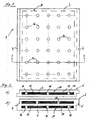
- Fig. 1 shows a schematic plan view of a heat insulating body 1 as a preferred embodiment of the present invention
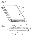
- Fig. 2 two preferred Layered structures of in Fig. 1 each shown thermal insulation body illustrated in a schematic sectional view.
- the heat-insulating body 1 will be first with reference to Fig. 2a ) and in the present embodiment comprises a molding 10 which is embedded in a heat-insulating cover layer 2 which completely surrounds the molding 10.
- the heat-insulating cover layer 2 is a hard foam, which in the present embodiment consists of expanded polystyrene.
- the molded article 10 may be embedded in any desired manner in the heat-insulating cover layer 2, with foaming of the molded article 10 in the cover layer 2 being preferred with regard to simple production and a good seal.
- the heat-insulating cover layer 2 does not have to take over the major part of the thermal insulation, it should nevertheless have certain heat-insulating properties in order to avoid unnecessary thermal bridges.
- the hard foam used in the present embodiment has, for example, a thermal conductivity of 0.030 W / (mK).
- the molded article 10 has a microporous thermal insulation material 12, which is accommodated in an airtight envelope 14.
- the microporous microdam material in the present embodiment is silica (SiO 2 ), although other suitable microporous materials may be used. It is inventively preferred that the material is designed such that the molding 10 has a thermal conductivity of at most 0.005 W / (mK).
- the negative pressure within the envelope 14 may be, for example, between 50 and 100 mbar.
- the airtight sheath 14 is made of aluminum in the present embodiment, but may be made of any material, such as a metal-plastic composite.
- the molding 10 has three adjacent through holes 16, wherein in the molding accordingly Fig. 1 a plurality of rows of through holes 16 may be provided. These passage openings are also filled in the present embodiment with the material of the heat-insulating cover layer 2, so that there is an excellent bond between the heat-insulating cover layer 2 and the molding 10.
- the through-holes 16 can be used for passing bolts, dowels or the like in order to secure the heat-insulating body 10 according to the invention, for example, to a wall to be insulated.
- the surface of the heat-insulating body according to the invention is provided with a marking which indicates the position of the individual passage openings 16.
- Fig. 2b shows a schematic sectional view of an alternative layer structure of the in Fig. 1 shown heat insulation body 1.
- the heat insulation body 1 comprises two sandwich-shaped moldings 10 which are spaced such that the heat-insulating cover layer 2 extends between the two moldings 10.
- the through holes 16 of in Fig. 2b ) shown offset from one another. If an attachment of the heat insulation body 1 is planned with dowels or the like, it is of course possible that some of the through holes of the two moldings 10 are also arranged in alignment, although in Fig. 2b ) Not shown.
- a plurality of heat-insulating bodies 1 are fastened in a planar manner next to one another on a building section, for example on a wall, a roof or even a floor surface.
- the in Fig. 2 shown heat insulation body 1 on the opposite edges with mutually complementary profiles 4, 6, which in the in Fig. 2 shown embodiment are formed in the manner of a Jardinnfalzes.
- the profiles 4, 6 are provided on all opposite edges.
- Fig. 4 shows a schematic sectional view of another preferred embodiment of the heat insulation body according to the invention 1.
- the upper part of Fig. 4 which is surrounded by a solid line, in principle, the structure of Fig. 2b ).
- This can be supplemented in the context of the invention by any number of additional moldings 10, which are also coated with a heat-insulating cover layer 2.
- three moldings are combined to form a thermal insulation panel 1 according to the invention, resulting in the arrangement of the moldings 10 and the heat-insulating cover layer 2 profilings 4, 6 in the manner of a tongue and groove arrangement.
Landscapes
- Physics & Mathematics (AREA)
- Engineering & Computer Science (AREA)
- Architecture (AREA)
- Acoustics & Sound (AREA)
- Electromagnetism (AREA)
- Civil Engineering (AREA)
- Structural Engineering (AREA)
- Building Environments (AREA)
- Thermotherapy And Cooling Therapy Devices (AREA)
- Thermal Insulation (AREA)
- Cookers (AREA)
- Secondary Cells (AREA)
Claims (11)
- Corps thermo-isolant (1) pour l'isolation d'ouvrages de construction, en particulier panneau d'isolation thermique, comprenant au moins une ébauche de forme (10) présentant un matériau d'isolation thermique (12) microporeux, logé dans un enveloppement (14) étanche à l'air,
le corps d'isolation thermique (1) présentant en outre une couche de couverture (2) isolant thermiquement, entourant complètement la au moins une ébauche de forme (10),
caractérisé en ce que la au moins une ébauche de forme (10) présente au moins une ouverture de passage (16), et
la au moins une ouverture de passage (16) de l'ébauche de forme est remplie par le matériau de la couche de couverture (2) isolant thermiquement. - Corps thermo-isolant selon la revendication 1, caractérisé en ce que la couche de couverture (2) isolant thermiquement présente une mousse dure, de préférence en polystyrène expansé, la au moins une ébauche de forme (10) étant de façon particulièrement préférée créée par moussage dans la couche de couverture (2).
- Corps thermo-isolant selon la revendication 1 ou 2, caractérisé en ce que le matériau d'isolation thermique (12) microporeux présente de l'acide silicique (SiO2) ou d'autres matériaux appropriés analogues.
- Corps thermo-isolant selon l'une des revendications précédentes, caractérisé en ce qu'une pression négative règne à l'intérieur de l'enveloppement (14) de la au moins une ébauche de forme (10).
- Corps thermo-isolant selon l'une des revendications précédentes, caractérisé en ce que la au moins une ébauche de forme (10) présente une conductivité thermique maximale de 0,005 W/(mK) et/ou la couche de couverture (2) isolant thermiquement présente une conductivité thermique maximale de 0,050 W/(mK).
- Corps thermo-isolant selon l'une des revendications précédentes, caractérisé en ce qu'il présente au moins deux ébauches de forme (10) disposées à la façon d'un sandwich, la couche de couverture (2) isolant thermiquement s'étendant de préférence entre chaque fois des ébauches de forme voisines.
- Corps thermo-isolant selon l'une des revendications précédentes, caractérisé en ce qu'il présente au moins deux ébauches de forme (10) disposées à la façon d'un sandwich, au moins quelques ouvertures de passage (16) d'ébauches de forme voisines étant disposées de façon décalée.
- Corps thermo-isolant selon l'une des revendications précédentes, caractérisé en ce qu'il présente au moins deux ébauches de forme disposées à la façon d'un sandwich, au moins quelques ouvertures de passage d'ébauches de forme voisines étant disposées sensiblement en alignement mutuel.
- Corps thermo-isolant selon la revendication 8, caractérisé en ce que la position des ouvertures de passage, en alignement, sur la surface du corps thermo-isolant est identifiable.
- Corps thermo-isolant selon l'une des revendications précédentes, caractérisé en ce que l'enveloppement (14) de la au moins une ébauche de forme (10) est composé d'aluminium ou de matière synthétique.
- Corps thermo-isolant selon l'une des revendications précédentes, caractérisé en ce qu'il présente, sur des bords opposés, des profilages (4, 6) mutuellement complémentaires, de préférence à la façon d'un pli étagé ou d'un agencement à rainure et languette.
Priority Applications (5)
| Application Number | Priority Date | Filing Date | Title |
|---|---|---|---|
| AT04003612T ATE363382T1 (de) | 2004-02-18 | 2004-02-18 | Wärmedämmkörper |
| DK04003612.1T DK1566264T4 (da) | 2004-02-18 | 2004-02-18 | Varmeisolerende legeme |
| SI200430407T SI1566264T2 (sl) | 2004-02-18 | 2004-02-18 | Toplotno izolacijsko telo |
| DE502004003939T DE502004003939D1 (de) | 2004-02-18 | 2004-02-18 | Wärmedämmkörper |
| EP04003612A EP1566264B2 (fr) | 2004-02-18 | 2004-02-18 | Corps thermo-isolant |
Applications Claiming Priority (1)
| Application Number | Priority Date | Filing Date | Title |
|---|---|---|---|
| EP04003612A EP1566264B2 (fr) | 2004-02-18 | 2004-02-18 | Corps thermo-isolant |
Publications (3)
| Publication Number | Publication Date |
|---|---|
| EP1566264A1 EP1566264A1 (fr) | 2005-08-24 |
| EP1566264B1 EP1566264B1 (fr) | 2007-05-30 |
| EP1566264B2 true EP1566264B2 (fr) | 2011-11-23 |
Family
ID=34707305
Family Applications (1)
| Application Number | Title | Priority Date | Filing Date |
|---|---|---|---|
| EP04003612A Expired - Lifetime EP1566264B2 (fr) | 2004-02-18 | 2004-02-18 | Corps thermo-isolant |
Country Status (5)
| Country | Link |
|---|---|
| EP (1) | EP1566264B2 (fr) |
| AT (1) | ATE363382T1 (fr) |
| DE (1) | DE502004003939D1 (fr) |
| DK (1) | DK1566264T4 (fr) |
| SI (1) | SI1566264T2 (fr) |
Cited By (2)
| Publication number | Priority date | Publication date | Assignee | Title |
|---|---|---|---|---|
| DE202012105100U1 (de) | 2011-12-31 | 2013-04-22 | Ideefa Gmbh & Co. Kg | Funktionale Lüftungsfassade mit Lüftungskanälen |
| DE202012105099U1 (de) | 2011-12-31 | 2013-04-22 | Ideefa Gmbh & Co. Kg | Funktionale Lüftungsfassade |
Families Citing this family (7)
| Publication number | Priority date | Publication date | Assignee | Title |
|---|---|---|---|---|
| DE202008012675U1 (de) * | 2008-09-24 | 2009-01-02 | SCHWENK DÄMMTECHNIK GMBH & Co KG | Dämmelement und Verwendung eines Dämmelementes |
| DE102008064572A1 (de) * | 2008-12-30 | 2010-07-08 | Alsecco Gmbh & Co Kg | Mehrschichtige Wärmedämmplatte und Verfahren zum Aufbau einer Wärmedämmfassade |
| DK2210991T3 (en) | 2009-01-21 | 2016-02-22 | Kingspan Insulation B V | external vægisolationssystem |
| FR2945557B1 (fr) | 2009-05-12 | 2011-07-08 | Electricite De France | Plancher isolant ameliore. |
| DE102009060401A1 (de) * | 2009-12-22 | 2011-07-07 | Fraunhofer-Gesellschaft zur Förderung der angewandten Forschung e.V., 80686 | Bauelement und Verfahren zum Betrieb eines Photovoltaikmoduls |
| DE202010005403U1 (de) | 2010-05-07 | 2010-08-26 | Friedrich, Jessica | Ausbildung und Anordnung von Isolierplatten für Fassaden, Decken, Wände oder Dächer |
| DE102010044789A1 (de) * | 2010-09-09 | 2012-03-15 | Calsitherm Verwaltungs Gmbh | Wärmedämmplatte mit eingelagerten hochwärmedämmenden bemantelten Platten sowie Bausatz dafür |
Citations (4)
| Publication number | Priority date | Publication date | Assignee | Title |
|---|---|---|---|---|
| DE4331590C1 (de) † | 1993-09-17 | 1994-08-11 | Porextherm Daemmstoffe Gmbh | Verpreßtes Isolier-Verbundformteil |
| JPH08303686A (ja) † | 1995-04-28 | 1996-11-22 | Mitsubishi Chem Corp | 真空断熱パネルおよびその製造方法 |
| WO2004001149A2 (fr) † | 2002-06-24 | 2003-12-31 | Sager Ag | Panneau a isolation par le vide, procede pour isoler thermiquement des objets et elements auxiliaires associes |
| DE10234409A1 (de) † | 2002-07-29 | 2004-02-12 | Va-Q-Tec Ag | Vakuumdämmplatte mit Einbuchtungen an den Rändern |
Family Cites Families (9)
| Publication number | Priority date | Publication date | Assignee | Title |
|---|---|---|---|---|
| JPS5796852A (en) * | 1980-12-09 | 1982-06-16 | Matsushita Electric Industrial Co Ltd | Heat insulating material |
| US4492725A (en) * | 1982-07-20 | 1985-01-08 | Matsushita Electric Industrial Co., Ltd. | Composite thermal insulator |
| DE3418637A1 (de) * | 1984-05-18 | 1985-11-21 | Wacker-Chemie GmbH, 8000 München | Waermedaemmformkoerper mit umhuellung |
| DE4344713A1 (de) * | 1993-12-27 | 1995-03-09 | Aabh Patent Holdings | Doppelwandige thermische Isolierung |
| US5681639A (en) * | 1994-09-21 | 1997-10-28 | Revall Co., Ltd. | Waterproof lightweight grain-tone decorative panel |
| DE29605338U1 (de) * | 1996-03-22 | 1997-07-17 | Bayer Ag, 51373 Leverkusen | Beidseitig mit aluminiumhaltiger Verbundfolie umhülltes Vakuumisolierpanell |
| HRP970104A2 (en) * | 1996-03-22 | 1998-02-28 | Bayer Ag | Vacuum insulating panels wraped on both sides by a foil containing metal or by a metal covering layer |
| DE19809316C2 (de) * | 1998-03-05 | 2000-11-09 | Plus Recycling Gmbh R | Wärmeisolationskörper und Mehrschichtkörper hierfür |
| WO2003002828A1 (fr) * | 2001-06-29 | 2003-01-09 | Sager Ag | Panneau a isolation par le vide |
-
2004
- 2004-02-18 AT AT04003612T patent/ATE363382T1/de active
- 2004-02-18 DK DK04003612.1T patent/DK1566264T4/da active
- 2004-02-18 DE DE502004003939T patent/DE502004003939D1/de not_active Expired - Lifetime
- 2004-02-18 SI SI200430407T patent/SI1566264T2/sl unknown
- 2004-02-18 EP EP04003612A patent/EP1566264B2/fr not_active Expired - Lifetime
Patent Citations (4)
| Publication number | Priority date | Publication date | Assignee | Title |
|---|---|---|---|---|
| DE4331590C1 (de) † | 1993-09-17 | 1994-08-11 | Porextherm Daemmstoffe Gmbh | Verpreßtes Isolier-Verbundformteil |
| JPH08303686A (ja) † | 1995-04-28 | 1996-11-22 | Mitsubishi Chem Corp | 真空断熱パネルおよびその製造方法 |
| WO2004001149A2 (fr) † | 2002-06-24 | 2003-12-31 | Sager Ag | Panneau a isolation par le vide, procede pour isoler thermiquement des objets et elements auxiliaires associes |
| DE10234409A1 (de) † | 2002-07-29 | 2004-02-12 | Va-Q-Tec Ag | Vakuumdämmplatte mit Einbuchtungen an den Rändern |
Cited By (2)
| Publication number | Priority date | Publication date | Assignee | Title |
|---|---|---|---|---|
| DE202012105100U1 (de) | 2011-12-31 | 2013-04-22 | Ideefa Gmbh & Co. Kg | Funktionale Lüftungsfassade mit Lüftungskanälen |
| DE202012105099U1 (de) | 2011-12-31 | 2013-04-22 | Ideefa Gmbh & Co. Kg | Funktionale Lüftungsfassade |
Also Published As
| Publication number | Publication date |
|---|---|
| DK1566264T4 (da) | 2011-12-19 |
| SI1566264T1 (sl) | 2007-10-31 |
| DE502004003939D1 (de) | 2007-07-12 |
| SI1566264T2 (sl) | 2012-03-30 |
| ATE363382T1 (de) | 2007-06-15 |
| EP1566264B1 (fr) | 2007-05-30 |
| EP1566264A1 (fr) | 2005-08-24 |
| DK1566264T3 (da) | 2007-09-24 |
Similar Documents
| Publication | Publication Date | Title |
|---|---|---|
| EP2666625B1 (fr) | Structure de mur et panneau d'isolation thermique | |
| EP3350383B1 (fr) | Plaque d'isolation et système d'isolation | |
| EP2216454A2 (fr) | Système d'isolation | |
| EP2726680B1 (fr) | Construction de façade pour l'isolation thermique et l'habillage de parois de bâtiments, et procédé de fabrication d'une telle construction de façade | |
| EP1566264B2 (fr) | Corps thermo-isolant | |
| DE202009008493U1 (de) | Wandaufbau und Wärmedämmplatte | |
| WO2016091244A2 (fr) | Système de panneaux pour aménager des pièces | |
| DE19516098B4 (de) | Deckenrandschalungselement sowie Verfahren und Vorrichtung zu seiner Herstellung | |
| EP2093340A1 (fr) | Plaque d'amortissement composite et système composite d'isolation thermique | |
| DE102011053499A1 (de) | Wärmedämmverbundeinrichtung | |
| EP2508692B1 (fr) | Panneau isolant et procédé de fabrication d'un panneau isolant | |
| DE4301565A1 (de) | Bauwerk-Leichtbauelement | |
| WO2013017622A1 (fr) | Élément multicouche | |
| AT509157A1 (de) | Verbundelement | |
| DE1084009B (de) | Verbundbauplatte | |
| AT409986B (de) | Vorsatzschale | |
| EP3212856B1 (fr) | Méthode pour produire un système composite d'isolation thermique | |
| DE3021537A1 (de) | Isolierung fuer den hoch- und tiefbau | |
| DE1534738A1 (de) | Isolier-Platte | |
| DE202019100960U1 (de) | Ankerelement für Herstellung einer Formfassade, Formfassade | |
| EP3034711B1 (fr) | Élement de coffrage de rive | |
| DE9209698U1 (de) | Zusammengesetzte Verschalung | |
| EP0834625A1 (fr) | Elément composé et procédé de fabrication | |
| AT13905U1 (de) | Wandelement, Fassadenelement und Fassade mit einer Vakuumisolationsplatte | |
| BE1023265B1 (de) | Isolierende Fassadenplatte |
Legal Events
| Date | Code | Title | Description |
|---|---|---|---|
| PUAI | Public reference made under article 153(3) epc to a published international application that has entered the european phase |
Free format text: ORIGINAL CODE: 0009012 |
|
| AK | Designated contracting states |
Kind code of ref document: A1 Designated state(s): AT BE BG CH CY CZ DE DK EE ES FI FR GB GR HU IE IT LI LU MC NL PT RO SE SI SK TR |
|
| AX | Request for extension of the european patent |
Extension state: AL LT LV MK |
|
| 17P | Request for examination filed |
Effective date: 20060124 |
|
| AKX | Designation fees paid |
Designated state(s): AT BE BG CH CY CZ DE DK EE ES FI FR GB GR HU IE IT LI LU MC NL PT RO SE SI SK TR |
|
| GRAP | Despatch of communication of intention to grant a patent |
Free format text: ORIGINAL CODE: EPIDOSNIGR1 |
|
| GRAS | Grant fee paid |
Free format text: ORIGINAL CODE: EPIDOSNIGR3 |
|
| GRAA | (expected) grant |
Free format text: ORIGINAL CODE: 0009210 |
|
| AK | Designated contracting states |
Kind code of ref document: B1 Designated state(s): AT BE BG CH CY CZ DE DK EE ES FI FR GB GR HU IE IT LI LU MC NL PT RO SE SI SK TR |
|
| PG25 | Lapsed in a contracting state [announced via postgrant information from national office to epo] |
Ref country code: FI Free format text: LAPSE BECAUSE OF FAILURE TO SUBMIT A TRANSLATION OF THE DESCRIPTION OR TO PAY THE FEE WITHIN THE PRESCRIBED TIME-LIMIT Effective date: 20070530 |
|
| REG | Reference to a national code |
Ref country code: GB Ref legal event code: FG4D Free format text: NOT ENGLISH |
|
| GBT | Gb: translation of ep patent filed (gb section 77(6)(a)/1977) |
Effective date: 20070605 |
|
| REG | Reference to a national code |
Ref country code: CH Ref legal event code: EP |
|
| REG | Reference to a national code |
Ref country code: IE Ref legal event code: FG4D Free format text: LANGUAGE OF EP DOCUMENT: GERMAN |
|
| REF | Corresponds to: |
Ref document number: 502004003939 Country of ref document: DE Date of ref document: 20070712 Kind code of ref document: P |
|
| REG | Reference to a national code |
Ref country code: CH Ref legal event code: NV Representative=s name: NOVAGRAAF INTERNATIONAL SA |
|
| REG | Reference to a national code |
Ref country code: RO Ref legal event code: EPE |
|
| PG25 | Lapsed in a contracting state [announced via postgrant information from national office to epo] |
Ref country code: ES Free format text: LAPSE BECAUSE OF FAILURE TO SUBMIT A TRANSLATION OF THE DESCRIPTION OR TO PAY THE FEE WITHIN THE PRESCRIBED TIME-LIMIT Effective date: 20070910 |
|
| REG | Reference to a national code |
Ref country code: SE Ref legal event code: TRGR |
|
| REG | Reference to a national code |
Ref country code: GR Ref legal event code: EP Ref document number: 20070402642 Country of ref document: GR |
|
| ET | Fr: translation filed | ||
| REG | Reference to a national code |
Ref country code: IE Ref legal event code: FD4D |
|
| PG25 | Lapsed in a contracting state [announced via postgrant information from national office to epo] |
Ref country code: PT Free format text: LAPSE BECAUSE OF FAILURE TO SUBMIT A TRANSLATION OF THE DESCRIPTION OR TO PAY THE FEE WITHIN THE PRESCRIBED TIME-LIMIT Effective date: 20071030 Ref country code: BG Free format text: LAPSE BECAUSE OF FAILURE TO SUBMIT A TRANSLATION OF THE DESCRIPTION OR TO PAY THE FEE WITHIN THE PRESCRIBED TIME-LIMIT Effective date: 20070830 Ref country code: IE Free format text: LAPSE BECAUSE OF FAILURE TO SUBMIT A TRANSLATION OF THE DESCRIPTION OR TO PAY THE FEE WITHIN THE PRESCRIBED TIME-LIMIT Effective date: 20070530 |
|
| PG25 | Lapsed in a contracting state [announced via postgrant information from national office to epo] |
Ref country code: SK Free format text: LAPSE BECAUSE OF FAILURE TO SUBMIT A TRANSLATION OF THE DESCRIPTION OR TO PAY THE FEE WITHIN THE PRESCRIBED TIME-LIMIT Effective date: 20070530 |
|
| PLBI | Opposition filed |
Free format text: ORIGINAL CODE: 0009260 |
|
| 26 | Opposition filed |
Opponent name: VARIOTEC SANDWICHELEMENTE GMBH & CO. KG Effective date: 20080221 |
|
| PLAX | Notice of opposition and request to file observation + time limit sent |
Free format text: ORIGINAL CODE: EPIDOSNOBS2 |
|
| PG25 | Lapsed in a contracting state [announced via postgrant information from national office to epo] |
Ref country code: IT Free format text: LAPSE BECAUSE OF FAILURE TO SUBMIT A TRANSLATION OF THE DESCRIPTION OR TO PAY THE FEE WITHIN THE PRESCRIBED TIME-LIMIT Effective date: 20070530 |
|
| NLR1 | Nl: opposition has been filed with the epo |
Opponent name: VARIOTEC SANDWICHELEMENTE GMBH & CO. KG |
|
| REG | Reference to a national code |
Ref country code: HU Ref legal event code: AG4A Ref document number: E002946 Country of ref document: HU |
|
| PLBB | Reply of patent proprietor to notice(s) of opposition received |
Free format text: ORIGINAL CODE: EPIDOSNOBS3 |
|
| PG25 | Lapsed in a contracting state [announced via postgrant information from national office to epo] |
Ref country code: MC Free format text: LAPSE BECAUSE OF NON-PAYMENT OF DUE FEES Effective date: 20080228 |
|
| PG25 | Lapsed in a contracting state [announced via postgrant information from national office to epo] |
Ref country code: EE Free format text: LAPSE BECAUSE OF FAILURE TO SUBMIT A TRANSLATION OF THE DESCRIPTION OR TO PAY THE FEE WITHIN THE PRESCRIBED TIME-LIMIT Effective date: 20070530 |
|
| PG25 | Lapsed in a contracting state [announced via postgrant information from national office to epo] |
Ref country code: CY Free format text: LAPSE BECAUSE OF FAILURE TO SUBMIT A TRANSLATION OF THE DESCRIPTION OR TO PAY THE FEE WITHIN THE PRESCRIBED TIME-LIMIT Effective date: 20070530 |
|
| PLAB | Opposition data, opponent's data or that of the opponent's representative modified |
Free format text: ORIGINAL CODE: 0009299OPPO |
|
| PG25 | Lapsed in a contracting state [announced via postgrant information from national office to epo] |
Ref country code: LU Free format text: LAPSE BECAUSE OF NON-PAYMENT OF DUE FEES Effective date: 20080218 |
|
| PG25 | Lapsed in a contracting state [announced via postgrant information from national office to epo] |
Ref country code: TR Free format text: LAPSE BECAUSE OF FAILURE TO SUBMIT A TRANSLATION OF THE DESCRIPTION OR TO PAY THE FEE WITHIN THE PRESCRIBED TIME-LIMIT Effective date: 20070530 |
|
| REG | Reference to a national code |
Ref country code: CH Ref legal event code: PFA Owner name: SCHWENK DAEMMTECHNIK GMBH & CO KG Free format text: SCHWENK DAEMMTECHNIK GMBH & CO KG#ISOTEXSTRASSE 1#D-86899 LANDSBERG (DE) -TRANSFER TO- SCHWENK DAEMMTECHNIK GMBH & CO KG#ISOTEXSTRASSE 1#D-86899 LANDSBERG (DE) |
|
| PUAH | Patent maintained in amended form |
Free format text: ORIGINAL CODE: 0009272 |
|
| STAA | Information on the status of an ep patent application or granted ep patent |
Free format text: STATUS: PATENT MAINTAINED AS AMENDED |
|
| 27A | Patent maintained in amended form |
Effective date: 20111123 |
|
| AK | Designated contracting states |
Kind code of ref document: B2 Designated state(s): AT BE BG CH CY CZ DE DK EE ES FI FR GB GR HU IE IT LI LU MC NL PT RO SE SI SK TR |
|
| REG | Reference to a national code |
Ref country code: DE Ref legal event code: R102 Ref document number: 502004003939 Country of ref document: DE |
|
| REG | Reference to a national code |
Ref country code: CH Ref legal event code: AEN Free format text: AUFRECHTERHALTUNG DES PATENTES IN GEAENDERTER FORM |
|
| REG | Reference to a national code |
Ref country code: NL Ref legal event code: T3 |
|
| REG | Reference to a national code |
Ref country code: DK Ref legal event code: T4 |
|
| REG | Reference to a national code |
Ref country code: SE Ref legal event code: RPEO |
|
| REG | Reference to a national code |
Ref country code: DE Ref legal event code: R102 Ref document number: 502004003939 Country of ref document: DE Effective date: 20111123 |
|
| REG | Reference to a national code |
Ref country code: GR Ref legal event code: EP Ref document number: 20120400060 Country of ref document: GR Effective date: 20120305 |
|
| REG | Reference to a national code |
Ref country code: DE Ref legal event code: R082 Ref document number: 502004003939 Country of ref document: DE Representative=s name: CLAUS-PETER FAUL UND KOLLEGEN, DE |
|
| PGFP | Annual fee paid to national office [announced via postgrant information from national office to epo] |
Ref country code: GB Payment date: 20130128 Year of fee payment: 10 Ref country code: FR Payment date: 20130227 Year of fee payment: 10 Ref country code: DK Payment date: 20130206 Year of fee payment: 10 Ref country code: SE Payment date: 20130214 Year of fee payment: 10 Ref country code: CH Payment date: 20130207 Year of fee payment: 10 Ref country code: RO Payment date: 20130214 Year of fee payment: 10 Ref country code: CZ Payment date: 20130301 Year of fee payment: 10 |
|
| REG | Reference to a national code |
Ref country code: DE Ref legal event code: R081 Ref document number: 502004003939 Country of ref document: DE Owner name: BACHL DAEMMTECHNIK GMBH & CO. KG, DE Free format text: FORMER OWNER: SCHWENK DAEMMTECHNIK GMBH & CO KG, 86899 LANDSBERG, DE Effective date: 20130313 Ref country code: DE Ref legal event code: R082 Ref document number: 502004003939 Country of ref document: DE Representative=s name: CLAUS-PETER FAUL UND KOLLEGEN, DE Effective date: 20130313 |
|
| PGFP | Annual fee paid to national office [announced via postgrant information from national office to epo] |
Ref country code: BE Payment date: 20130207 Year of fee payment: 10 Ref country code: SI Payment date: 20121224 Year of fee payment: 10 Ref country code: NL Payment date: 20130206 Year of fee payment: 10 Ref country code: GR Payment date: 20130227 Year of fee payment: 10 |
|
| PGFP | Annual fee paid to national office [announced via postgrant information from national office to epo] |
Ref country code: AT Payment date: 20130211 Year of fee payment: 10 |
|
| PGFP | Annual fee paid to national office [announced via postgrant information from national office to epo] |
Ref country code: HU Payment date: 20130423 Year of fee payment: 10 |
|
| BERE | Be: lapsed |
Owner name: SCHWENK DAMMTECHNIK G.M.B.H. & CO KG Effective date: 20140228 |
|
| REG | Reference to a national code |
Ref country code: NL Ref legal event code: V1 Effective date: 20140901 |
|
| REG | Reference to a national code |
Ref country code: DK Ref legal event code: EBP Effective date: 20140228 |
|
| REG | Reference to a national code |
Ref country code: CH Ref legal event code: PL Ref country code: SE Ref legal event code: EUG |
|
| REG | Reference to a national code |
Ref country code: AT Ref legal event code: MM01 Ref document number: 363382 Country of ref document: AT Kind code of ref document: T Effective date: 20140218 |
|
| REG | Reference to a national code |
Ref country code: GR Ref legal event code: ML Ref document number: 20120400060 Country of ref document: GR Effective date: 20140903 |
|
| GBPC | Gb: european patent ceased through non-payment of renewal fee |
Effective date: 20140218 |
|
| PG25 | Lapsed in a contracting state [announced via postgrant information from national office to epo] |
Ref country code: LI Free format text: LAPSE BECAUSE OF NON-PAYMENT OF DUE FEES Effective date: 20140228 Ref country code: CH Free format text: LAPSE BECAUSE OF NON-PAYMENT OF DUE FEES Effective date: 20140228 Ref country code: RO Free format text: LAPSE BECAUSE OF NON-PAYMENT OF DUE FEES Effective date: 20140218 Ref country code: NL Free format text: LAPSE BECAUSE OF NON-PAYMENT OF DUE FEES Effective date: 20140901 Ref country code: CZ Free format text: LAPSE BECAUSE OF NON-PAYMENT OF DUE FEES Effective date: 20140218 Ref country code: GR Free format text: LAPSE BECAUSE OF NON-PAYMENT OF DUE FEES Effective date: 20140903 |
|
| REG | Reference to a national code |
Ref country code: FR Ref legal event code: ST Effective date: 20141031 |
|
| PG25 | Lapsed in a contracting state [announced via postgrant information from national office to epo] |
Ref country code: SE Free format text: LAPSE BECAUSE OF NON-PAYMENT OF DUE FEES Effective date: 20140219 Ref country code: SI Free format text: LAPSE BECAUSE OF NON-PAYMENT OF DUE FEES Effective date: 20140219 Ref country code: HU Free format text: LAPSE BECAUSE OF NON-PAYMENT OF DUE FEES Effective date: 20140219 Ref country code: AT Free format text: LAPSE BECAUSE OF NON-PAYMENT OF DUE FEES Effective date: 20140218 |
|
| REG | Reference to a national code |
Ref country code: SI Ref legal event code: KO00 Effective date: 20141007 |
|
| PG25 | Lapsed in a contracting state [announced via postgrant information from national office to epo] |
Ref country code: BE Free format text: LAPSE BECAUSE OF NON-PAYMENT OF DUE FEES Effective date: 20140228 Ref country code: FR Free format text: LAPSE BECAUSE OF NON-PAYMENT OF DUE FEES Effective date: 20140228 Ref country code: GB Free format text: LAPSE BECAUSE OF NON-PAYMENT OF DUE FEES Effective date: 20140218 Ref country code: DK Free format text: LAPSE BECAUSE OF NON-PAYMENT OF DUE FEES Effective date: 20140228 |
|
| PGFP | Annual fee paid to national office [announced via postgrant information from national office to epo] |
Ref country code: DE Payment date: 20230216 Year of fee payment: 20 |
|
| REG | Reference to a national code |
Ref country code: DE Ref legal event code: R071 Ref document number: 502004003939 Country of ref document: DE |