EP2178442B1 - Catheter for in vivo imaging - Google Patents
Catheter for in vivo imaging Download PDFInfo
- Publication number
- EP2178442B1 EP2178442B1 EP08796187.6A EP08796187A EP2178442B1 EP 2178442 B1 EP2178442 B1 EP 2178442B1 EP 08796187 A EP08796187 A EP 08796187A EP 2178442 B1 EP2178442 B1 EP 2178442B1
- Authority
- EP
- European Patent Office
- Prior art keywords
- catheter
- distal
- sheath
- drive shaft
- lumen
- Prior art date
- Legal status (The legal status is an assumption and is not a legal conclusion. Google has not performed a legal analysis and makes no representation as to the accuracy of the status listed.)
- Active
Links
- 238000011503 in vivo imaging Methods 0.000 title claims description 5
- 229910052751 metal Inorganic materials 0.000 claims description 66
- 239000002184 metal Substances 0.000 claims description 65
- 230000003287 optical effect Effects 0.000 claims description 30
- 239000000463 material Substances 0.000 claims description 28
- 239000013307 optical fiber Substances 0.000 claims description 26
- 229910001000 nickel titanium Inorganic materials 0.000 claims description 18
- HLXZNVUGXRDIFK-UHFFFAOYSA-N nickel titanium Chemical compound [Ti].[Ti].[Ti].[Ti].[Ti].[Ti].[Ti].[Ti].[Ti].[Ti].[Ti].[Ni].[Ni].[Ni].[Ni].[Ni].[Ni].[Ni].[Ni].[Ni].[Ni].[Ni].[Ni].[Ni].[Ni] HLXZNVUGXRDIFK-UHFFFAOYSA-N 0.000 claims description 15
- BASFCYQUMIYNBI-UHFFFAOYSA-N platinum Chemical compound [Pt] BASFCYQUMIYNBI-UHFFFAOYSA-N 0.000 claims description 15
- PXHVJJICTQNCMI-UHFFFAOYSA-N Nickel Chemical compound [Ni] PXHVJJICTQNCMI-UHFFFAOYSA-N 0.000 claims description 12
- 229910045601 alloy Inorganic materials 0.000 claims description 9
- 239000000956 alloy Substances 0.000 claims description 9
- 229910052697 platinum Inorganic materials 0.000 claims description 8
- 239000010935 stainless steel Substances 0.000 claims description 8
- 229910001220 stainless steel Inorganic materials 0.000 claims description 8
- -1 copper-zinc-aluminum Chemical compound 0.000 claims description 7
- 229910052759 nickel Inorganic materials 0.000 claims description 6
- RYGMFSIKBFXOCR-UHFFFAOYSA-N Copper Chemical compound [Cu] RYGMFSIKBFXOCR-UHFFFAOYSA-N 0.000 claims description 5
- RTAQQCXQSZGOHL-UHFFFAOYSA-N Titanium Chemical compound [Ti] RTAQQCXQSZGOHL-UHFFFAOYSA-N 0.000 claims description 5
- HCHKCACWOHOZIP-UHFFFAOYSA-N Zinc Chemical compound [Zn] HCHKCACWOHOZIP-UHFFFAOYSA-N 0.000 claims description 5
- 229910052802 copper Inorganic materials 0.000 claims description 5
- 239000010949 copper Substances 0.000 claims description 5
- PCHJSUWPFVWCPO-UHFFFAOYSA-N gold Chemical compound [Au] PCHJSUWPFVWCPO-UHFFFAOYSA-N 0.000 claims description 5
- 229910052737 gold Inorganic materials 0.000 claims description 5
- 239000010931 gold Substances 0.000 claims description 5
- 229910001092 metal group alloy Inorganic materials 0.000 claims description 5
- 229910052715 tantalum Inorganic materials 0.000 claims description 5
- GUVRBAGPIYLISA-UHFFFAOYSA-N tantalum atom Chemical compound [Ta] GUVRBAGPIYLISA-UHFFFAOYSA-N 0.000 claims description 5
- 229910052719 titanium Inorganic materials 0.000 claims description 5
- 239000010936 titanium Substances 0.000 claims description 5
- 229910052720 vanadium Inorganic materials 0.000 claims description 5
- LEONUFNNVUYDNQ-UHFFFAOYSA-N vanadium atom Chemical compound [V] LEONUFNNVUYDNQ-UHFFFAOYSA-N 0.000 claims description 5
- 229910052725 zinc Inorganic materials 0.000 claims description 5
- 239000011701 zinc Substances 0.000 claims description 5
- 239000000560 biocompatible material Substances 0.000 claims description 3
- 238000003384 imaging method Methods 0.000 description 32
- 238000012014 optical coherence tomography Methods 0.000 description 24
- 208000027418 Wounds and injury Diseases 0.000 description 22
- 239000010410 layer Substances 0.000 description 22
- 238000005452 bending Methods 0.000 description 17
- 238000000034 method Methods 0.000 description 15
- 239000000523 sample Substances 0.000 description 11
- 239000012530 fluid Substances 0.000 description 10
- 229920001343 polytetrafluoroethylene Polymers 0.000 description 9
- 239000004810 polytetrafluoroethylene Substances 0.000 description 9
- 229920000642 polymer Polymers 0.000 description 8
- 239000000853 adhesive Substances 0.000 description 7
- 230000001070 adhesive effect Effects 0.000 description 7
- 238000013461 design Methods 0.000 description 7
- 239000007787 solid Substances 0.000 description 7
- 229920002614 Polyether block amide Polymers 0.000 description 6
- 238000002608 intravascular ultrasound Methods 0.000 description 6
- 238000012360 testing method Methods 0.000 description 6
- 210000005166 vasculature Anatomy 0.000 description 6
- 230000008859 change Effects 0.000 description 5
- 238000000576 coating method Methods 0.000 description 5
- 238000005259 measurement Methods 0.000 description 5
- 230000009467 reduction Effects 0.000 description 5
- 201000009310 astigmatism Diseases 0.000 description 4
- 230000006378 damage Effects 0.000 description 4
- 230000001419 dependent effect Effects 0.000 description 4
- 239000000835 fiber Substances 0.000 description 4
- 238000011010 flushing procedure Methods 0.000 description 4
- 230000037361 pathway Effects 0.000 description 4
- 238000003856 thermoforming Methods 0.000 description 4
- 239000004593 Epoxy Substances 0.000 description 3
- 239000011324 bead Substances 0.000 description 3
- 210000004204 blood vessel Anatomy 0.000 description 3
- 238000009954 braiding Methods 0.000 description 3
- 230000000694 effects Effects 0.000 description 3
- 238000010438 heat treatment Methods 0.000 description 3
- 238000003780 insertion Methods 0.000 description 3
- 230000037431 insertion Effects 0.000 description 3
- 229910052741 iridium Inorganic materials 0.000 description 3
- 230000033001 locomotion Effects 0.000 description 3
- 239000002243 precursor Substances 0.000 description 3
- 239000002356 single layer Substances 0.000 description 3
- 230000007704 transition Effects 0.000 description 3
- 238000003466 welding Methods 0.000 description 3
- 229920001774 Perfluoroether Polymers 0.000 description 2
- 210000002376 aorta thoracic Anatomy 0.000 description 2
- 238000013459 approach Methods 0.000 description 2
- 230000005540 biological transmission Effects 0.000 description 2
- 238000005253 cladding Methods 0.000 description 2
- 239000011248 coating agent Substances 0.000 description 2
- 238000004891 communication Methods 0.000 description 2
- 239000002131 composite material Substances 0.000 description 2
- 210000004351 coronary vessel Anatomy 0.000 description 2
- 238000005530 etching Methods 0.000 description 2
- 238000001727 in vivo Methods 0.000 description 2
- GKOZUEZYRPOHIO-UHFFFAOYSA-N iridium atom Chemical compound [Ir] GKOZUEZYRPOHIO-UHFFFAOYSA-N 0.000 description 2
- 238000005304 joining Methods 0.000 description 2
- 239000007788 liquid Substances 0.000 description 2
- 239000003550 marker Substances 0.000 description 2
- 229910000734 martensite Inorganic materials 0.000 description 2
- 239000007769 metal material Substances 0.000 description 2
- VNWKTOKETHGBQD-UHFFFAOYSA-N methane Chemical compound C VNWKTOKETHGBQD-UHFFFAOYSA-N 0.000 description 2
- 238000012805 post-processing Methods 0.000 description 2
- 230000004044 response Effects 0.000 description 2
- 239000011343 solid material Substances 0.000 description 2
- 239000000126 substance Substances 0.000 description 2
- 238000013519 translation Methods 0.000 description 2
- 238000007514 turning Methods 0.000 description 2
- 239000013598 vector Substances 0.000 description 2
- XLYOFNOQVPJJNP-UHFFFAOYSA-N water Substances O XLYOFNOQVPJJNP-UHFFFAOYSA-N 0.000 description 2
- 208000004221 Multiple Trauma Diseases 0.000 description 1
- 244000208734 Pisonia aculeata Species 0.000 description 1
- 239000004696 Poly ether ether ketone Substances 0.000 description 1
- 208000012287 Prolapse Diseases 0.000 description 1
- FAPWRFPIFSIZLT-UHFFFAOYSA-M Sodium chloride Chemical compound [Na+].[Cl-] FAPWRFPIFSIZLT-UHFFFAOYSA-M 0.000 description 1
- 238000005270 abrasive blasting Methods 0.000 description 1
- AZDRQVAHHNSJOQ-UHFFFAOYSA-N alumane Chemical group [AlH3] AZDRQVAHHNSJOQ-UHFFFAOYSA-N 0.000 description 1
- 238000000137 annealing Methods 0.000 description 1
- 229910001566 austenite Inorganic materials 0.000 description 1
- JUPQTSLXMOCDHR-UHFFFAOYSA-N benzene-1,4-diol;bis(4-fluorophenyl)methanone Chemical compound OC1=CC=C(O)C=C1.C1=CC(F)=CC=C1C(=O)C1=CC=C(F)C=C1 JUPQTSLXMOCDHR-UHFFFAOYSA-N 0.000 description 1
- 230000015572 biosynthetic process Effects 0.000 description 1
- 238000007664 blowing Methods 0.000 description 1
- 230000000747 cardiac effect Effects 0.000 description 1
- 238000012512 characterization method Methods 0.000 description 1
- 238000012669 compression test Methods 0.000 description 1
- 238000010276 construction Methods 0.000 description 1
- 238000001816 cooling Methods 0.000 description 1
- 229920001577 copolymer Polymers 0.000 description 1
- 238000005520 cutting process Methods 0.000 description 1
- 238000003066 decision tree Methods 0.000 description 1
- 238000005553 drilling Methods 0.000 description 1
- 230000002526 effect on cardiovascular system Effects 0.000 description 1
- 238000001125 extrusion Methods 0.000 description 1
- 238000005755 formation reaction Methods 0.000 description 1
- 230000002496 gastric effect Effects 0.000 description 1
- 239000003292 glue Substances 0.000 description 1
- 238000000227 grinding Methods 0.000 description 1
- 238000007373 indentation Methods 0.000 description 1
- 208000014674 injury Diseases 0.000 description 1
- 230000001788 irregular Effects 0.000 description 1
- 238000005461 lubrication Methods 0.000 description 1
- 238000004519 manufacturing process Methods 0.000 description 1
- 239000011159 matrix material Substances 0.000 description 1
- 230000007246 mechanism Effects 0.000 description 1
- 150000002739 metals Chemical class 0.000 description 1
- 239000000203 mixture Substances 0.000 description 1
- 238000000465 moulding Methods 0.000 description 1
- 239000003345 natural gas Substances 0.000 description 1
- 230000001537 neural effect Effects 0.000 description 1
- 230000007935 neutral effect Effects 0.000 description 1
- 230000002093 peripheral effect Effects 0.000 description 1
- 239000004033 plastic Substances 0.000 description 1
- 229920003023 plastic Polymers 0.000 description 1
- 238000005498 polishing Methods 0.000 description 1
- 229920002530 polyetherether ketone Polymers 0.000 description 1
- 239000002861 polymer material Substances 0.000 description 1
- 230000008569 process Effects 0.000 description 1
- 238000012545 processing Methods 0.000 description 1
- 230000002250 progressing effect Effects 0.000 description 1
- 238000010791 quenching Methods 0.000 description 1
- 230000000171 quenching effect Effects 0.000 description 1
- 230000002787 reinforcement Effects 0.000 description 1
- 238000010008 shearing Methods 0.000 description 1
- 238000004088 simulation Methods 0.000 description 1
- 239000002893 slag Substances 0.000 description 1
- 239000011780 sodium chloride Substances 0.000 description 1
- 230000003595 spectral effect Effects 0.000 description 1
- 238000005482 strain hardening Methods 0.000 description 1
- 238000009864 tensile test Methods 0.000 description 1
- BFKJFAAPBSQJPD-UHFFFAOYSA-N tetrafluoroethene Chemical group FC(F)=C(F)F BFKJFAAPBSQJPD-UHFFFAOYSA-N 0.000 description 1
- 230000001225 therapeutic effect Effects 0.000 description 1
- 229920001169 thermoplastic Polymers 0.000 description 1
- 239000004416 thermosoftening plastic Substances 0.000 description 1
- 230000009466 transformation Effects 0.000 description 1
- 238000002604 ultrasonography Methods 0.000 description 1
- 238000012285 ultrasound imaging Methods 0.000 description 1
- 238000007666 vacuum forming Methods 0.000 description 1
- 238000004804 winding Methods 0.000 description 1
Images


Classifications
-
- A—HUMAN NECESSITIES
- A61—MEDICAL OR VETERINARY SCIENCE; HYGIENE
- A61B—DIAGNOSIS; SURGERY; IDENTIFICATION
- A61B5/00—Measuring for diagnostic purposes; Identification of persons
- A61B5/68—Arrangements of detecting, measuring or recording means, e.g. sensors, in relation to patient
- A61B5/6846—Arrangements of detecting, measuring or recording means, e.g. sensors, in relation to patient specially adapted to be brought in contact with an internal body part, i.e. invasive
- A61B5/6847—Arrangements of detecting, measuring or recording means, e.g. sensors, in relation to patient specially adapted to be brought in contact with an internal body part, i.e. invasive mounted on an invasive device
- A61B5/6852—Catheters
-
- A—HUMAN NECESSITIES
- A61—MEDICAL OR VETERINARY SCIENCE; HYGIENE
- A61B—DIAGNOSIS; SURGERY; IDENTIFICATION
- A61B5/00—Measuring for diagnostic purposes; Identification of persons
- A61B5/0059—Measuring for diagnostic purposes; Identification of persons using light, e.g. diagnosis by transillumination, diascopy, fluorescence
- A61B5/0062—Arrangements for scanning
- A61B5/0066—Optical coherence imaging
-
- A—HUMAN NECESSITIES
- A61—MEDICAL OR VETERINARY SCIENCE; HYGIENE
- A61B—DIAGNOSIS; SURGERY; IDENTIFICATION
- A61B8/00—Diagnosis using ultrasonic, sonic or infrasonic waves
- A61B8/12—Diagnosis using ultrasonic, sonic or infrasonic waves in body cavities or body tracts, e.g. by using catheters
-
- A—HUMAN NECESSITIES
- A61—MEDICAL OR VETERINARY SCIENCE; HYGIENE
- A61B—DIAGNOSIS; SURGERY; IDENTIFICATION
- A61B8/00—Diagnosis using ultrasonic, sonic or infrasonic waves
- A61B8/44—Constructional features of the ultrasonic, sonic or infrasonic diagnostic device
- A61B8/4444—Constructional features of the ultrasonic, sonic or infrasonic diagnostic device related to the probe
- A61B8/4461—Features of the scanning mechanism, e.g. for moving the transducer within the housing of the probe
-
- A—HUMAN NECESSITIES
- A61—MEDICAL OR VETERINARY SCIENCE; HYGIENE
- A61M—DEVICES FOR INTRODUCING MEDIA INTO, OR ONTO, THE BODY; DEVICES FOR TRANSDUCING BODY MEDIA OR FOR TAKING MEDIA FROM THE BODY; DEVICES FOR PRODUCING OR ENDING SLEEP OR STUPOR
- A61M25/00—Catheters; Hollow probes
- A61M25/01—Introducing, guiding, advancing, emplacing or holding catheters
- A61M2025/0183—Rapid exchange or monorail catheters
-
- A—HUMAN NECESSITIES
- A61—MEDICAL OR VETERINARY SCIENCE; HYGIENE
- A61M—DEVICES FOR INTRODUCING MEDIA INTO, OR ONTO, THE BODY; DEVICES FOR TRANSDUCING BODY MEDIA OR FOR TAKING MEDIA FROM THE BODY; DEVICES FOR PRODUCING OR ENDING SLEEP OR STUPOR
- A61M25/00—Catheters; Hollow probes
- A61M25/0043—Catheters; Hollow probes characterised by structural features
- A61M25/005—Catheters; Hollow probes characterised by structural features with embedded materials for reinforcement, e.g. wires, coils, braids
- A61M25/0052—Localized reinforcement, e.g. where only a specific part of the catheter is reinforced, for rapid exchange guidewire port
Definitions
- the present invention relates generally to a catheter for in vivo imaging. More particularly, the present invention pertains to a catheter for imaging within a mammalian body, including luminal systems, such as imaging the vasculature system, including, without limitation, cardiac vasculature, peripheral vasculature and neural vasculature.
- luminal systems such as imaging the vasculature system, including, without limitation, cardiac vasculature, peripheral vasculature and neural vasculature.
- Intravascular probes rotate at a nonuniform angular velocity even though the motor rotates at a uniform angular velocity. This is a problem because the angles assumed by the image processor in assembling the image vectors into the cross-sectional image of the body lumens are different from the actual angles at which the image vectors were taken. This causes the cross-sectional image of the blood vessel to be distorted in the azimuthal and radial direction. The resulting distortion is referred as Nonuniform Rotational Distortion ("NURD").
- NURD Nonuniform Rotational Distortion
- WO 2007/084995 reports a general imaging catheter having a guidewire provision located at its distal tip and utilizes an inner core to impart rotational motion to an imaging element.
- US Pat. No. 5,443,457 reports a catheter system having a sheath and a flexible working shaft within a working lumen of the sheath where the sheath includes a monorail-type guidewire lumen at its distal end, and a stiffening member adjacent to a side port of the monorail guidewire lumen to inhibit prolapse of the catheter as it is introduced past a bend or curve over a guidewire.
- US 2003/004412 A1 reports a catheter with an Optical Coherence Tomography imaging element coupled to a rotary shaft to impart rotation to the imaging element and obtain high resolution tomograms of tissue by low-coherent interference with scattered light from the tissue.
- US Pat. No. 6,078,831 reports an intravascular imaging guidewire comprising a drive shaft with a nitinol telescoping extension.
- US 2001/037073 A1 reports a catheter system including a counter-wound coil structure, which may either expand or contract as the drive cable is being rotated to strengthen the drive cable.
- a catheter for in vivo imaging comprises an optical train coupled to a rotary drive shaft at least partially disposed within a sheath body, wherein the sheath body defining a central lumen and a distal tip, the central lumen terminating at the distal tip and the distal tip having a guidewire lumen formed therein, wherein the sheath body is monolithic; the optical train is positioned within the central lumen and further comprises an optical fiber, a gradient index lens, a prism, a housing concentrically engaged about the optical fiber, the gradient index lens, and the prism; and the rotary drive shaft comprises a proximal metal hypotube coupled to a distal stranded hollow core, wherein the proximal metal hypotube comprises variable stiffness along a longitudinal axis of the hypotube, and the distal stranded hollow core of the rotary drive shaft is coupled to a proximal end of the housing.
- the monolithic sheath body may include a single continuous piece of material containing no joints from the proximal end of the sheath body to a distal end of the distal tip.
- the housing may further comprise a metal tube having an opening in a wall thereof, the opening being in optical alignment with the prism.
- the rotary drive shaft may define a rotary drive shaft lumen and the distal stranded hollow core is coupled to the housing, wherein the optical fiber passes axially through the rotary drive shaft lumen.
- the distal stranded hollow core may comprise a plurality of metal wires wound in a helical configuration.
- the plurality of metal wires of the distal stranded hollow core may comprise nitinol.
- the stranded hollow core may be coated with a biocompatible material.
- the proximal metal hypotube may be coaxially coupled to at least a portion of the distal stranded hollow core.
- the proximal metal hypotube may be a material selected from the group consisting of nitinol, stainless steel, tantalum, gold, platinum, titanium, copper, nickel, vanadium, zinc metal alloy, copper-zinc-aluminum alloy, and combinations thereof.
- the proximal metal hypotube may be nitinol.
- the distal stranded hollow core may comprise an inner helical stranded portion and an outer helical stranded portion.
- a catheter 10 comprising a monolithic outer sheath 20 including a central sheath lumen extending substantially the entire length of the monolithic outer sheath 20 and a monolithically formed flexible tip 28.
- the term "monolithic” or “monolithically formed” is without any joints or junctions formed by thermal, chemical or mechanical bonding.
- the catheter 10 construct for in vivo imaging, particularly, imaging of anatomical passageways, such as cardiovascular, neurovascular, gastrointestinal, genitor-urinary tract, or other anatomical luminal structures.
- the catheter 10 is coupled to an imaging modality, and in one embodiment the imaging modality is an Optical Coherence Tomography ("OCT") system.
- OCT is an optical interferometric technique for imaging subsurface tissue structure with micrometer-scale resolution.
- the imaging modality is an ultrasound imaging modality, such as intravascular ultrasound (“IVUS), either alone or in combination with OCT imaging.
- the OCT system may include tunable laser or broadband light source or multiple tunable laser sources with corresponding detectors, and may be a spectrometer based OCT system or a Fourier Domain OCT system, as disclosed in U.S. Provisional Application 60/949,467 , herein incorporated by reference.
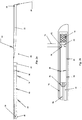
- the catheter 10 may be integrated with IVUS by an OCT-IVUS catheter for concurrent imaging. As shown in Fig. 1 , the catheter 10 comprises the monolithic outer sheath 20 that houses an acoustical or optical train 30.
- the optical train 20 includes a length of d, and the catheter 10 includes a length of D from the distal portion of the FORJ 60 to the distal monolithic tip 28 of the catheter monolithic outer sheath 20.
- the optical train 30 rotates under the influence of an external rotary drive motor (not shown) coupled to a rotary drive shaft 40 and an optical fiber 50 through a Fiber Optic Rotary Junction 60 ("FORJ"), thereby also rotating the optical train 30.
- the rotary drive shaft 40 includes a drive shaft lumen, through which the optical fiber 50 is concentrically or coaxially disposed.
- a plug-in connector 62 is coupled to the proximal end of the rotary drive shaft 40, to couple the catheter 10 to the rotary drive motor.
- the plug-in connector may include a Subscription Channel (SC) - Angled Physical Contact (APC) connectors to ensure lower insertion loss and back reflection.
- the FORJ 60 may include fiber pigtail, ST, FC, SC, FC/UPC receptacles, or any combination receptacles on the rotor or the stator side (Princetel, Lawrenceville, NJ).
- the connector 62 may include a centering boot to center the optical fiber with respect to the rotary drive shaft 40.
- the centering boot includes a first lumen to accept the optical fiber and a second lumen to accept the rotary drive shaft 40.
- the FORJ is provided to permit rotation of the optical fiber and rotary shaft while maintaining optical communication with the radiant light source (e.g., tunable laser or broadband emitter) with minimal insertion loss and return loss performance.
- the rotary drive motor imparts rotational movement to the rotary drive shaft 40 either by a DC brushless motor and the like.
- the rotary drive motor may rotate at revolutions per minute (RPM) for a 360 degree rotation of the rotary drive shaft 40.
- a linear pull back mechanism may also be coupled to the rotary drive shaft, which may include a stepping motor.
- the monolithic outer sheath 20 is held stationary, relative to the rotary drive shaft 40, by use of a permanently affixed retaining bead 42 that is connected to the frame of the rotary drive motor.
- the bead includes a first lumen and a second lumen smaller than the first lumen, whereby the second lumen communicates through the first lumen.
- the bead is a single machined aluminum part that is attached to the monolithic outer sheath 20 by means of mechanical thread engagement and adhesive.
- the rotary drive shaft 40 is concentrically or coaxially positioned within the central lumen of the monolithic outer sheath 20 and substantially extends along the longitudinal length D of the central lumen. Coaxially engagement between the rotary drive shaft 40 and the central lumen of the monolithic outer sheath 20 may be accomplished with the OD of the rotary drive shaft 40 matching the ID of the monolithic outer sheath 20 or varying the OD of the rotary drive shaft to the ID of the monolithic outer sheath 20.
- the rotary drive shaft 40 terminates at its distal end in proximity to the distal end of the central lumen adjacent the proximal end of the catheter 10.
- the optical train 30 is carried by the rotary drive shaft 40, with the optical fiber 50 running the length of the rotary drive shaft 40 through the drive shaft lumen.
- the rotary drive shaft 40 permits transmission of torque from the rotary motor to the optical train 30 along the entire length of the catheter shaft.
- the rotary dive shaft 40 includes having sufficient torsional rigidity or torqueability and lateral flexibility or flexion to navigate potentially tortuous anatomical pathways while minimizing NURD to ensure accurate imaging.
- Torqueability is the ability of the rotary drive shaft to be turned or rotated while traversing bends or turns in the patient's vasculature.
- the rotary drive shaft 40 includes a hypotube metal over a proximal portion or the entire proximal section of the rotary drive shaft 40.
- the rotary drive shaft 40 includes a stranded hollow core shaft extending the substantial length of the rotary drive shaft 40.
- the stranded hollow core shaft may comprise a plurality of helically wound wire strands so that mechanical rotation of the rotary drive shaft is in the same direction as the helical wire strands.
- the stranded hollow core shaft may include an inner stranded drive shaft and outer stranded drive shaft, where in outer stranded drive shaft is wound in the opposite helical direction than the inner stranded drive shaft.
- a protection bearing 70 may be coupled to either the stranded hollow core shaft or the hypotube metal.
- the stranded hollow core shaft, the hypotube metal, or a combination thereof provides sufficient lateral flexibility to ensure access through highly tortuous passageways, such as the aortic arch and coronary arteries.
- the hypotube metal is concentrically or coaxially fitted over a proximal portion or the entire proximal section of the stranded hollow core shaft.
- the coaxial fitting of the hypotube metal over the stranded hollow core shaft may be accomplished by allowing the OD of the stranded hollow core shaft to vary from the ID of the hypotube metal tube by about 0.0254 to 0.2286 mm (0.001 to 0.009 inches).
- the highly flexible stranded hollow core shaft lessens NURD by the relatively less flexible hypotube metal at the more distal end of the catheter to permit greater distal end flexion or lateral flexibility.
- the rotary drive shaft also maintains the pushability, the ability of the catheter to be efficiently and easily pushed through the vasculature of the patient without damage to the catheter or patient, getting blocked, kinked, whipped, etc.
- the rotary drive shaft 40 includes a shortened hypotube metal shaft attached in a generally overlapping attachment with a section of stranded hollow core shaft, with there being a very slight mismatch in the outer diameters between the hypotube metal and the stranded hollow core shaft to permit concentric or coaxial engagement and attachment between the respective end sections.
- the hypotube metal and the stranded hollow core shaft may have generally the same outer diameter to permit end-to-end connection, such as a butt weld there between.
- the stranded hollow core shaft includes single layer uni-directional and multi-layer directional winding configurations when coupled to the hypotube metal shaft.
- the monolithic outer sheath 20 is fabricated of an optically transparent polymer, such as, for example, perfluoroalkoxy (PFA) polymer, polytetrafluoroethylene (PTFE) partially covered with a polyether block amide (Pebax®) at the distal end, or tetrafluoroethylene and hexafloropropylene co-polymer (FEP).
- PFA perfluoroalkoxy
- PTFE polytetrafluoroethylene
- Pebax® polyether block amide
- FEP tetrafluoroethylene and hexafloropropylene co-polymer
- the optically transparent polymer is transparent in the spectral region of light being used for imaging.
- Similar biocompatible optically transparent polymers having similar properties of lubricity, flexibility, optical clarity, biocompatible and sterilizability may alternatively be employed to form the catheter shaft.
- FEP is used to fabricate the catheter sheath.
- the catheter sheath is fabricated in a monolithic manner such that the central lumen terminates at the atraumatic monolithic tip without any intervening joints. Atraumatic is not producing injury or damage.
- a rapid exchange guidewire lumen 22 is formed entirely within the atraumatic monolithic tip with both the proximal guidewire port and the distal guidewire port accessing the guidewire lumen distal the termination of the central lumen of the catheter sheath.
- the guidewire is the thin wire over which the catheter rides.
- a guidewire lumen 22 is formed in the distal portion of the monolithic outer sheath 20, while a central sheath lumen 32 extends proximally from the distal portion of the monolithic outer sheath 20.
- the guidewire lumen 22 includes a guidewire exit 24 and a guidewire entrance 26.
- the guidewire lumen 22 is positioned entirely in the distal terminus of the central sheath lumen 32 such that the guidewire (not shown) may be rapidly exchanged and does not interfere with the rotational movement of the optical train 30, rotary drive shaft 40 or the protection bearing 70 within the central lumen of the catheter sheath 20.
- the rotary drive shaft 40 includes the protection bearing 70, which houses the distal end optics or distal end acoustics at the distal end of the catheter 10, as shown in Fig. 2b .
- the protection bearing 70 may be coaxially mounted over the distal end optics, or alternatively, molded over the distal end optics or the distal end optics molded into the protection bearing 70.
- the protection bearing 70 may include a diameter to coaxially engage the distal end optics to ensure a 1:1 rotation of the protection bearing 70 with the distal end optics.
- the protection bearing 70 may include a Platinum/Iridium tube and is formed with an opening 92.
- the opening may be positioned in optical alignment with the prism 90 in order to permit light to pass through the opening 92 and optically communicate with the sample being imaged, as shown in Fig. 2b .
- the Platinum/Iridium tube may comprise about 75-97 % Pt and about 3-25% Ir, which provides radiopacity.
- the metal hypotube of the rotary drive shaft replaces the protection bearing 70, where the metal hypotube extends coaxially over the distal end optics and includes an opening for the distal end optics.
- the protection bearing 70 may include other metals nitinol, i.e.
- the protection bearing 70 may include an epoxy rounded tip to ensure smooth rotational translation of the protection bearing 70.
- the protection bearing 70 includes a bearing plug 74 within the distal portion of the protection bearing's distal lumen.
- the bearing plug 74 may coaxially fit into the distal portion of the protection bearing 70, or may be secured by adhesive, welding, and the like.
- the bearing plug 74 may include a metal material, alternatively a metal/polymer material, alternatively stainless steel.
- the optical train 30 includes the monolithic outer sheath 20 the optical fiber 50 in association with the rotary drive shaft 40, the protection bearing 70 housing a ferrule/gradient index lens (“GRIN”) assembly 80 at a distal end of the optical fiber 50, as shown in Fig. 2a .
- the ferrule/GRIN assembly 80 optically coupled to a prism 90 or mirror to conduct light between the optical fiber 50, ferrule/GRIN assembly and the sample being imaged.
- the distal end of the optical train 30, i.e., the distal end optical fiber 50, the ferrule/GRIN lens assembly and the prism 90, are all secured within the protection bearing 70 and rotate with the protection bearing 70, under the influence of the rotary drive shaft 40, within the central lumen 32 of the catheter sheath 20.
- the optical train 30 rotates under the influence of an external rotary drive motor coupled to the rotary drive shaft and optical fiber through the FORJ 60, thereby also rotating the ferrule/ GRIN lens 80 assembly and the prism 90 to emit optical energy 94 at an angle and through 360 degrees around the monolithic outer sheath 20.
- the ferrule/GRIN assembly 80 includes a GRIN lens 82 and a ferrule 84.
- the optical fiber 50 may include a core, cladding and buffer and is optically coupled to the ferrule 84.
- the ferrule 84 is optically coupled to the GRIN lens 82 and prism 90 to transmit light between the optical fiber 50, GRIN lens 82 and the sample being imaged.
- the ferrule 84 at a distal end of the optical fiber 50 supports and terminates the distal end of the optical fiber 50, where the optical fiber 50 may be coaxially fitted within the ferrule 84.
- the ferrule may include a lumen and a tapered cladding to coaxially couple the core of the optical fiber 50.
- the fiber 50 may not include the buffer.
- the optical fiber 50 may be potted or adhesively secured to the ferrule 84 at point 86 with optical glue, curing adhesive, and the like, as to provide a coaxial alignment of the optical fiber and the ferrule.
- the GRIN lens 82 is optically coupled to a distal surface of the ferrule 84 at point 88, such as by optically transparent adhesive.
- the GRIN lens 82 and the ferrule 84 may include an angled engagement, where the angle offset of the distal end of the ferrule 84 matches the angle offset of the proximal end of the GRIN lens 82.
- the prism or mirror 90 is optically coupled to the distal surface of the GRIN lens 82 at point 98, such as by optically transparent adhesive.
- the distal surface of the GRIN lens 82 may include an angled offset.
- the prism 90 may include a right angled prism and the prism angles may be constructed to provide balancing of astigmatism introduced by the sheath.
- An optical pathway is formed along the longitudinal axis of the rotary drive shaft 40, the catheter sheath 20, and protection bearing 70.
- the prism or mirror 90 serves to redirect at least some portion of the light away from the central longitudinal axis and generally radially outward, through the optically transparent portion of the monolithic outer sheath 20 to communicate with the body tissue being imaged throughout 360 degrees.
- the prism angles may be constructed to provide a balancing of astigmatism introduced by the catheter sheath.
- the incident light may not necessarily all be used for imaging, where additional optical energy beams are for therapeutic purposes or possibly some other energy source.
- the monolithic outer sheath 20 may include an outer layer 110 and an inner layer 120 to form a laminate structure 100.
- the outer layer 110 may be constructed of Pebax® extending the substantial length along the proximal portion of the catheter sheath and the outer layer 110 provides greater structural rigidity relative to the inner layer 120.
- the inner layer 120 may be constructed of PTFE, with the PTFE inner layer 120 extending distally from the Pebax® outer layer 110 and forming the most distal section, which is optically transparent and flexible to permit optical communication to the sample and greater traversability for the catheter during insertion or retraction within the anatomical passageway.
- Fig. 3b representing background art for understanding the invention shows the solid monolithically formed tip 28 and a base layer 130 and a top layer 140.
- the base layer 130 maybe constructed of Pebax® substantially along the base of the catheter sheath and provides greater structural rigidity relative to the top layer 140. The greater structural rigidity allows the monolithic outer sheath greater pushability along the proximal portion of the monolithic outer sheath.
- the base layer 130 may include a plug 132.
- the plug 132 may include a space between the protection bearing 70 when the protection bearing 70 engages with the monolitic outer sheath 20.
- the plug 132 may include an angled engagement with distal portion of the sheath lumen to impart increased flexibility to the distal end of the monolithic outer sheath 20.
- the plug 132 may include polymeric material, including, but not limited to PTFE, FEP, and the like.
- the top layer 140 may be constructed of PTFE, with the PTFE top layer 140 extending distally from the Pebax® base layer 130, which provides greater flexibility along the distal end of the monolithic outer sheath for navigating tortuous pathways.
- the layers of the monolithic sheath 20 include a coating either on the outer layers or inner layers for smooth transitioning and less friction during navigation. Such coatings may be biocompatible, polymeric, saline, and the like.
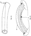
- Fig. 4 depicts the monolithic outer sheath 20 prior to the guidewire lumen 22 being formed.
- the solid monolithically formed tip 28 is formed by first providing a tubular catheter sheath precursor 150, preferably placing a forming mandrel in the central sheath lumen 152 of the tubular catheter sheath precursor 150, then thermoforming the solid tip 154 into a desired shape.
- Thermoforming is any process of forming thermoplastic sheet, which consists of heating the sheet and forcing it onto a mold surface. The sheet or film is heated between infrared, natural gas, or other heaters to its forming temperature, then it is stretched over or into a temperature-controlled, single-surface mold.
- the sheet is held against the mold surface unit until cooled, and the formed part is then trimmed from the sheet.
- thermoforming including vacuum forming, pressure forming, twin-sheet forming, drape forming, free blowing, simple sheet bending, and the like.
- the shape of the monolithic tip 28 maybe rounded, radiused, tapered, or generally frustroconical with an atraumatic distal end formed.
- a radiused tip includes an angle of curvature that is derived from the radius of the outer sheath OD, where the angle or degree of curvature equals the reciprocal of the radius (1/R).
- the guidewire lumen 156 may then be formed by bending the solid distal tip 28 and drilling a straight hole angularly through the distal end and to a lateral side of the distal tip, then releasing the bend in the tip to provide distal end and proximal side guidewire ports and a curved lumen.
- the tip may be formed with the guidewire lumen 156 during the thermoforming process by providing the appropriate mold.
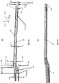
- the resulting guidewire lumen 156 may or may not maintain a straight longitudinal axis, where the longitudinal axis runs along the x-axis of the sheath 20, as shown in phantom in Fig. 5 .
- the guidewire lumen 156 includes a straight longitudinal axis 160 and a non-longitudinal axis 162.
- the straight longitudinal axis 160 is included for some length along the distal portion of the catheter sheath body and associated with the guidewire entrance 162.
- the non-longitudinal axis 162 is included for some length along the proximal portion of the catheter body and is associated with the guidewire exit 164.
- the angled measurements for the non-longitudinal axis 162 near the guidewire exit can be any angle relative to the longitudinal axis 160 as to provide for the rapid exchange of the guidewire and no kinking or whipping of the guidewire.
- the angle or degree of curvature for the non-longitudinal axis relative the longitudinal axis is about 0.1 to 10 degrees, about 1 to 8 degrees, or about 1.5 to 6 degrees.
- the monolithic outer sheath 20 includes the absence of or potential for uneven surfaces that may irritate or damage tissues in anatomical passageways or interfere with the guiding catheter during retraction or advancement of the catheter, the absence of joints which could separate and dangerously embolize, and the absence of joints which could leak fluid into or out of the sheath.
- the central lumen of the outer catheter sheath may be filled with a fluid that could serve to (a) provide lubrication between the monolithic outer sheath and the rotary shaft, (b) reduce optical astigmatism originating from the cylindrical curvature of the inner sheath surface due to the lower index of refraction mismatch of liquid when compared with air, (c) provide additional column strength and kink resistance to the catheter, (d) viscously dampen NURD, or (e) provide negative torsional feedback to stabilize or dampen non-uniformities in rotation.
- the monolithic design of the catheter outer sheath and the monolithic atraumatic tip further permit different engineering of material properties along the length of the monolithic outer sheath.
- the durometer of the catheter sheath may be varied along the length of the catheter sheath during manufacture of the sheath precursor material; the inner and/or outer diameter of the catheter sheath may be made to vary, such as by tapering, along the length of the continuous monolithic tube; the wall thicknesses of the catheter sheath and the concomitant flexibility profiles may be varied along the longitudinal length of the catheter sheath, or the catheter sheath may be variably reinforced to alter the flexibility profiles along the longitudinal axis of the catheter sheath, such as by applying a braiding material, a concentric reinforcement, such as another overlaid tube, or combinations of the foregoing.
- the braiding material may be a polymer formed from conventional braiding machines.
- the durometer is the hardness of the material, as defined as the material's resistance to permanent indentation.
- the two most common scales, using slightly different measurement systems, are the ASTM D2240 type A and type D scales.
- the A scale is for softer plastics, while the D scale is for harder ones.
- the ASTM D2240-00 testing standard calls for a total of 12 scales, depending on the intended use; types A, B, C, D, DO, E, M, O, OO, OOO, OOO-S, and R. Each scale results in a value between 0 and 100, with higher values indicating a harder material.
- the monolithic catheter sheath 200 includes a sheath lumen 210, a guidewire lumen 220, and a monolithic atraumatic tip 230.
- the sheath lumen 210 includes a rounded distal end 212 for the placement of the optical train 30.
- the sheath lumen 210 includes a longitudinal axis substantially along the x-axis direction of the monolithic catheter sheath 200.
- the guidewire lumen 220 includes a guidewire exit 222, a guidewire entrance 224, and a distal marker band 226.
- the distal marker band 226 is of a radiopaque material.
- the guidewire lumen 220 includes a diameter 236, which may remain constant along the longitudinal length of the guidewire lumen 220.
- the longitudinal axis of the guidewire lumen 220 is at a slight angle A and offset from the longitudinal axis of the sheath lumen 210.
- the offset angle A may be about 1 to 20 degrees, from about 1 to 5 degrees, and from about 2 to 4 degrees
- the offset angle A minimizes space between the guidewire and the catheter body, which helps to minimize chance of the guidewire getting entangled when crossing stents.
- the catheter sheath 200 also includes a buffer 240 of solid material between guide wire lumen 220 and the sheath lumen 210 to prevent the passage of fluid and offset the guidewire lumen 220 from the sheath lumen 210.
- the guide wire lumen 220 is approximately straight along its longitudinal axis, as to permit free passage of guide wire (not shown).
- the guidewire lumen 220 includes a guidewire lumen wall 228 that includes at least two thicknesses.
- the guidewire lumen wall 228 includes a first thickness 232 near the guidewire exit 222 slightly larger than a second thickness 234 near the guidewire entrance 224.
- the guidewire lumen wall 228 first thickness near guidewire exit 222 evenly distributes strain on the monolithic catheter sheath 200 and prevents kinking of the guidewire at the guidewire exit 222.
- An outer transparent view of the monolithic catheter sheath 200 is shown in Fig. 6b , showing the sheath lumen 210 and guidewire lumen 220 in phantom.
- a flushing port 250 is coupled to the sheath lumen 210 and the exterior of the catheter sheath 200.
- the flushing port 250 between the sheath lumen 210 and the exterior of the catheter sheath 200 allows an operator to flush air or any fluid out of the sheath lumen 210.
- the monolithic catheter sheath 200 may use standard luer connections at the proximal end of the catheter sheath 200 to provide the flushing fluid.
- Luer connection systems are the standard way of attaching catheters, IV tubes, and so on to each other, and they consist of round male and female interlocking tubes, slightly tapered to hold together better with even just a simple pressure/twist fit. Luer connections can either be a luer slip, or can have an additional outer rim of threading.
- the embodiment of the monolithic catheter sheath 200 includes a flushing port 252 coupled to the guidewire lumen 220 and the sheath lumen 210 to allow the operator to flush air or fluid out of the sheath lumen 210, as shown in phantom in Fig. 7b .
- the monolithic catheter sheath 300 includes a sheath lumen 310, a guidewire lumen 320, and a plug 330.
- the sheath lumen 310 includes a longitudinal axis substantially along the x-axis of the monolithic catheter sheath 300.
- the sheath lumen 310 houses the protection bearing 312 coupled to the drive shaft 314 and the OCT imaging port 316.
- the guidewire lumen 320 includes a guidewire exit 322, a guidewire entrance 324, and a curvature 326 offset lumen.
- the distal portion of the guidewire lumen 320 includes a longitudinal axis along the x-axis of the catheter sheath 300.
- the catheter sheath 300 also includes a plug 330 of solid material between guidewire lumen 320 and the sheath lumen 310 to prevent the passage of fluid and offset the guidewire lumen 320 from the sheath lumen 310.
- the curvature lumen 326 is offset from the distal longitudinal axis of the guidewire lumen and the longitudinal axis of the sheath lumen 310. The curvature 326 offset minimizes space between the guidewire (not shown) and the monolithic catheter body, which helps to minimize the wire entangling when crossing stents and tortuous pathways.
- An outer transparent view of the monolithic catheter sheath 300 embodiment is shown in Fig. 8b , with the sheath lumen 310, the guidewire lumen 320, and the curvature lumen 326 in phantom.
- the rotary drive shaft 40 connects the distal end optical train and optics to the rotary motor and the transmission of rotary torque to the distal end optics while minimizing NURD.
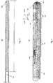
- the rotary drive shaft 40 may comprise entirely of a hypotube metal drive shaft 400, a stranded hollow core shaft 500 or a combination of the hypotube metal drive shaft 400 joined with the stranded hollow core shaft 500, or alternating combinations of the hypotube metal drive shaft 400 and stranded hollow core shaft 500.
- the hypotube metal drive shaft may comprise nitinol, i.e.
- the metal hypotube shaft 400 may include a reinforced telescoping inner assembly coaxially coupled over the proximal end of the metal hypotube shaft 400.
- the reinforced telescoping inner assembly is stronger than the metal hypotube shaft 400 to prevent buckling, bending, or shearing.
- the reinforced telescoping inner assembly includes a metal tube stainless steel design coupled to the centering boot to permit longer push-forward capability and provide improved liquid seal during flush.
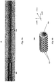
- the stranded hollow core shaft 500 comprises a stranded hollow core or lumen 510 including a plurality of helically wound metal wires 520.
- the helically wound metal wires 520 include an outer surface and a diameter, which may exist at about 0.005 to about 0.0127 cm (about 0.002 to about 0.005 inches).
- the helical wound metal wires 520 are fixedly engaged with neighboring metal wires on their respective outer surfaces. The fixed engagement of the helical wound metal wires 520 completely encases the stranded hollow lumen 510.
- the stranded hollow core shaft 500 with the helical wound metal wires 520 are different from a spring coil wire, in that a spring coil wire consists of a single metal wire wound about itself in a helical fashion.
- the helically wound metal wires 520 may exist in any number to form the stranded hollow core shaft 500, in one embodiment from about 2 to 15 wires, from about 3 to 12 wires, or from about 4 to 10 wires in the helical configuration.
- An individual helical wound wire 520 may consist of only one metal filament; however, the individual helical wound wire 520 may include more than one metal filament.
- the helically wound metal wires 520 may comprise nitinol, i.e.
- the stranded hollow core shaft 500 may be helically wound and that portion may consist of an inner helical stranded portion and an outer helical stranded portion.
- the inner helical stranded portion may wind in the opposite direction as the outer helical stranded portion.
- the stranded hollow core shaft 500 may include a helical wound configuration including a Picks Per Centimeter (PPC), where there may be about 1.97 to 5.91, about 2.76 to 4.72 PPC and about 3.15 to 3.94 PPC (Picks Per Inch (PPI), where there may be about 5 to 15, about 7 to 12 PPI, and about 8 to 10 PPI) for the helical configuration.
- the helical wound configuration may have alternating symmetries along the longitudinal axis of the rotary drive shaft, such as an infinite helical symmetry, n-fold helical symmetry, and non-repeating helical symmetry.
- the stranded hollow core shaft 500 may be coated with some biocompatible material, such as PTFE or similar polymers to provide lubricity within the monolithic catheter sheath.
- the distal part of the rotary drive shaft 40 may be the stranded hollow core 500 design, where flexibility is required at the entry point to the body. From the proximal portion to the distal portion of the rotary drive shaft 40, a single layer or double layer wound stranded hollow core may be included at the proximal portion, a hypotube metal drive shaft 400, and a single layer or double layer wound at the distal portion as to have a flexible distal tip.
- the hypotube metal drive shaft 400 may include a solid wall extending substantially the entire longitudinal length of the central lumen of the rotary drive shaft 40 in combination with the stranded hollow core shaft 500, which (a) increases torsional rigidity of the rotating shaft and reduces NURD; (b) increases column strength or axial rigidity to improve the pushability of the catheter assembly; (c) reduces or eliminates the possibility of the stranded or coiled hollow core shaft unraveling or disassociating under the torsional forces applied; (d) improves the frictional interface by replacing an interrupted or more concentrated load transference between individual strands and the monolithic outer sheath with a continuous and more distributed load across the solid-walled hypotube metal shaft; and (e) the hypotube metal shaft offers a good fluid seal against the monolithic outer sheath over the proximal section of a fluid-filled catheter due to the solid-walled design.
- the solid-walled hypotube metal drive shaft 400 may, alternatively be used in conjunction with the stranded hollow core shaft by either butt-joining a distal end of the hypotube metal shaft 400 onto a proximal end of the stranded hollow core shaft 500, as illustrated in Fig. 10a .
- the butt-joining of the two ends may be accomplished by welding or adhesives to ensure little to no vibration during rotation.
- a portion of the hypotube metal shaft 400 may be concentrically or coaxially engaged or fitted with a portion of the stranded hollow core shaft 500, as is illustrated in Fig. 10b .
- the coaxial fitting ensures a 1:1 rotation of the hypotube metal shaft 400 and the stranded hollow core shaft 500 to ensure little to no vibration during rotation.
- the stranded hollow core shaft 500 is coaxially engaged with the protection bearing 70, where the protection bearing may include an epoxy rounded tip 72 to ensure smooth rotational translation of the protection bearing 70.
- the wall-thickness of the hypotube metal shaft 400 may be varied along its length to impart variable stiffness along the longitudinal axis of the hypotube metal shaft 400. In this manner, relatively thinner wall-thicknesses may be formed distally than those formed more proximally, to impart greater flexibility at the distal end of the hypotube metal shaft 400.
- the wall thickness may be varied by extrusion processing, mechanical means, such as grinding, abrasive blasting, turning, by chemical or electrochemical means, such as electro-polishing or etching, or by combinations of the foregoing.
- slots, holes or other aperture shape formations may be formed by means of cutting, etching, ablating or other means to generate designs in the tubular structure which permit additional flexibility of the distal region of the hypotube metal shaft 400 while retaining substantial torsional rigidity.
- the rotary drive shaft 40 design can include the following considerations: (1) the material type and geometry of the material that comprise a given segment; and (2) a number of distinct material segments when progressing from the proximal to distal portions of the catheter.
- the design of the rotary drive shaft 40 includes setting the lateral flexibility of the material at the proximal end to a specific point and increasing the lateral flexibility from the proximal end to the distal segments of the rotary drive shaft.
- a higher lateral flexibility is desired in portions of the catheter that experience the greatest geometric curvature when used for imaging.
- the diameter of the rotary drive shaft may become gradually or stepwise smaller from the proximal end to the distal portions of the rotary drive shaft. By reducing the wall thickness or by reducing the ID and OD or both the ID and OD, the diameter of the rotary drive shaft becomes smaller.
- the geometry of catheter at the surgical entry point and the geometry of the human coronary tract generally put these regions at the surgical entry point to the body and the aortic arch and the coronary blood vessel being interrogated.
- the material type and the geometry of the materials in a given segment may vary in the rotary drive shaft. Different geometries are recognized for a given segment of the rotary drive shaft. Examples include, but are not limited to: (1) homogeneous solid (e.g., nitinol, PEEK, or some polymer); (2) stranded hollow core shaft (single wound, double counter-wound, or triple coil-wound or generally multiple wound); (3) braided multi-stranded hollow core shaft; (4) fibrous composite (fibers in a matrix); (5) patterned solid (#1 with patterned holes or apertures); and (6) patterned composite (#4 with patterned holes or apertures).
- homogeneous solid e.g., nitinol, PEEK, or some polymer
- stranded hollow core shaft single wound, double counter-wound, or triple coil-wound or generally multiple wound
- braided multi-stranded hollow core shaft (4) fibrous composite (fibers in a matrix
- a two segment rotary drive shaft includes the metal hypotube shaft in the proximal portion and a stranded hollow core 5 at the distal portion.
- the joints between any segments may be joined end-to-end with for example a butt-couple, weld, epoxy or other jointing technique.
- an overlapping style of joint may be used, i.e. male-female joints, or by coaxial engagement, concentric alignment, and the like. Connection of the segments of an overlapping style of joint may be accomplished by means of welding, adhesive, or over-molding given that at least one element is polymer.
- a gradation may be accomplished by a change in material properties along the length of the rotary drive shaft.
- the material properties may be adjusted such as the modulus of elasticity of the material via methods including, but not limited to annealing, carburization, or heat treat and subsequent quenching techniques.
- the transition temperature (A f ) along the length by means of heat treatment, cold working, or some combination thereof.
- M f is the temperature at which the transition to Martensite is finished during cooling. Accordingly, during heating As and A1 are the temperatures at which the transformation from Martensite to Austenite starts and finishes.
- Nitinol is typically composed of approximately 50 to 55.6% nickel by weight. Making small changes in the composition can change the transition temperature of the alloy significantly. For this reason, nitinol may or may not be superelastic at certain temperatures, thus allowing the modulus of elasticity to be adjusted according to the temperature of use.
- the load can be reduced by reducing the friction or by reducing the section modulus.
- contact points that are continuously changing during pullback which may consist of: (1) the surface of the stranded hollow core shaft strands (2) the ID of the FEP monolithic outer sheath if no water, fill solution, or coatings are present; and (3) the surface of the OD of the protection bearing to the ID of the FEP monolithic outer sheath if no water, fill solution, or coatings are present.
- the normal force is between: (1) the shaft OD and sheath ID; and/or (2) the protection bearing OD and sheath ID.
- F k ⁇ k ⁇ d 3 t 8 cl .
- the two competing mass moment of inertia terms are J and I.
- the two opposing factors are friction due to bending and torsional rigidity.
- Moment of inertial (I) from the section modulus in the bending portion is compared to the polar second moment of area (J).
- Fig. 12a is a chart illustrating the Torsion Term 620 and the Bending Term 622.
- Fig. 12b is a chart illustrating the change in the Torsion/Bending Ratio 630 while measuring for NURD during angular deflection testing of the rotary drive shaft within an outer monolithic sheath.
- the characteristics of the rotary drive shaft and/or the outer monolithic sheath may be tested from various mechanical testing methods, such as tensile tests, torsion test, bending test or compression test.
- the torsion and bending tests provide useful information about the type of deformation of the rotary drive shaft and catheter monolithic sheath to account for NURD.
- the measurement of rotary position of the catheter 10 may be used as input for a NURD-reduction software approach.
- the catheter 10 is coupled to the proximal motor system 700, including a torque sensor 710, a rotary motor 720, a linear motor 730, and a computer/software program 740 operably coupled to the motor system 700.
- the method for estimating NURD in the rotational imaging catheter 10 is by measuring the torque on proximale end of the catheter 10 with the torque sensor 710. If NURD is characterized (e.g, in the form of an equation or data points representing angular position of imaging transducer vs. time) then removal of or correcting for NURD via post-processing of the image is straightforward. To truly characterize NURD, the angular position of the rotating imaging transducer must be known.
- Methods for determining this position include active approaches such as distal accelerometers or passive approaches such as encoding a circumferential line pattern in the catheter outer sheath which can be detected within the image itself (OCT, IVUS, etc.) or encoding the catheter sheath thickness into the angular position and detecting within the OCT or IVUS image.
- the proximal torque measurement is indirect because measurements are made on the proximal end of the driveshaft, however the torsional properties of the driveshaft are known and constant, and thus the mechanical response of the distal tip can be estimated by the mechanical response of the proximal shaft.
- Knowledge of the angular position vs. time is shown in Fig. 19 , and is an important input to correct for NURD.
- the y-axis of the graph in Fig. 19 is the rotational time, where 1 rotation has occurred.
- a passive method for indirectly determining the angular position of the rotating imaging transducer 750 as a function of time is by forcing the rotating transducer to be in an eccentric location with respect to the outer wall of the stationary sheath.
- the outer wall of the stationary sheath 752 can be visualized in the image and because it is eccentric with respect to the transducer rotation.
- the outer sheath 752 includes a thickness S.
- the outer wall of the stationary sheath will experience a geometrical image distortion (i.e. the apple-like cross-sectional shape) when NURD is present and the catheter is not centered on the vessel axis, as shown in Fig. 20b .
- the eccentricity of the rotating portion with respect to the outer sheath 752 must only be large enough to visualize in the image (i.e. the difference in wall thickness as a function of angle due to the eccentricity must be larger than the depth resolution of the imaging modality).
- the image of the outer sheath 752 outer diameter OD 754 and the wall thickness S is compared to the a priori known eccentricity of the sheath. This comparison can be based on curve fitting to analytical models, statistical decision tree, or other numerical methods.
- the method for determining the thickness data from the angular position of a sensor within a catheter having a sheath wall of varying thickness can be found in U.S. Patent No. 6,450,964 .
- the beam distortion (e.g. astigmatism) from the eccentrically oriented sheath will be minimal because the wall thickness vs. angle can be small relative to the beam diameter as it passes through the sheath. This can be further minimized by matching the wave speed in the sheath material with the fluid media bordering the ID and OD of the sheath (i.e. refractive index if OCT, acoustic impedance if ultrasound).
- OCT images of a NURD mask for the catheter with a vessel in phantom are shown in Figs. 14 , 15 , and 16 .
- the examples span the range from mild to moderate NURD with for each case the angular position vs. time and the resulting B-scan profile.
- the catheter OCT system records 1000 A-lines per rotation.
- a tube called a resolution mask or NURD mask 650 is placed over the catheter system, as shown in Fig. 13 .
- the NURD mask 650 may include several different sizes to measure the effects of NURD at different diameters.
- the NURD mask includes a plurality of slots 652, where the widths of the slots may range from about 0.157 to about 0.314 mm.
- the slots 652 intervene with struts 654.
- the slot width and strut width may be equal in diameter to give 20 slots 652 around the circumference of the NURD mask 650. No slag or burrs shall be present on finished NURD mask 650.
- the NURD mask 650 may include an aperture 656 to secure the NURD mask 650 to the catheter. The diameter of the aperture 656 may range from 0.3-0.6 mm.
- the NURD mask 650 may be constructed from metal, stainless steel, nitinol, and the like.
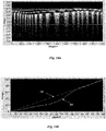
- Fig. 14a a rectangular OCT image of the NURD mask 650 with moderate NURD, where the NURD mask 650 includes 20 evenly spaced slots and where the tube slot width equals the tube strut width.
- the x-axis is sample number on the graph of Fig. 14a and the vessel is in phantom.
- the theoretical line for no NURD 640 is the non-white curve
- the actual measured NURD 642 is the white curve
- the vertical distance between the white actual measured NURD 642 and non-white theoretical line 640 for no NURD determines the amount of NURD.
- the more distance between the non-white theoretical line 640 for no NURD and the white actual measured NURD 642 indicates more NURD.
- moderate NURD is shown between samples # 160 and #200.
- Fig. 15a a rectangular OCT image of the NURD mask with minimal NURD with the image of the NURD mask including 20 evenly spaced slots, and where the tube slot width equals the tube strut width.
- the x-axis is sample number on the graph of Fig. 15a and the vessel is in phantom.
- Fig. 15b the chart shows where the actual imaging beam is at any given point in time for one rotation
- X-axis sample #
- Y-axis A-scan number with 1000 A-scans per rotation.
- the theoretical line for no NURD 640 is the non-white curve
- the actual measured NURD 644 is the white curve
- the vertical distance between the white actual measured NURD 644 and the non-white theoretical line 640 determines the amount of NURD.
- the more distance between the non-white theoretical line 640 for no NURD and the white actual measured NURD 644 indicates more NURD.
- Fig. 15b minimal NURD is shown between samples # 1 and #360, with little to no vertical distance between the non-white theoretical line 640 and the white actual measured NURD 644.
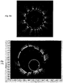
- Figs. 16a - 16c show polar images of the OCT catheter 10 system with the NURD mask.
- Fig. 16a shows the catheter 10 in a straight vessel where the NURD is small.
- Fig. 16b shows the catheter with the NURD mask in a sharp 90 bend in the distal end where the NURD is small.
- Fig. 16c shows the catheter in a tortuous model LAD Co-Pilot within a tight valve and small NURD values.
- the polar images in Figs. 16a - 16c show the OCT catheter 10 in the center of the vessel.
- the lack of radial distortion may be due to the centering of the OCT catheter.
- the catheter is centered in the images of the NURD mask in the vessel phantoms and the apple shape of the radial distortion only appears when the catheter is offset from the center.
- Figs. 17a - 17c are polar OCT images demonstrating the simulated NURD effects in the same image where the catheter is not centered can show an apple-like shape of the vessel.
- the image was recorded with the catheter 10 in vivo in a pig coronary placed with a stent. In order to see the apple-like cross sections of the radial distortion, the catheter can be positioned in an off-center position.
- Fig. 17a is an image showing original/ less NURD. In the original/least NURD case, the catheter is off center in the vessel lumen and the slots are fairly evenly spaced radially around the perimeter.
- a simulation NURD program was created to simulate NURD with the catheter, vessel, etc. in the Fig.17a image in post-processing steps.
- Fig. 17a is polar OCT images demonstrating the simulated NURD effects in the same image where the catheter is not centered can show an apple-like shape of the vessel.
- the image was recorded with the catheter 10 in vivo in a
- FIG. 17b is a simulated image showing medium NURD.
- the lumen cross section is increasingly warped with the characteristic apple shape and the stent strut spacing becomes more irregular.
- Fig. 17c is a simulated image showing extreme NURD, with the lumen warped into an apple-like shape.
- Figs. 17a -17c suggest that a non-centrally located catheter in combination non-uniform rotational velocity can result in azimuthal and radial distortion in the polar OCT image.
Description
- The present invention relates generally to a catheter for in vivo imaging. More particularly, the present invention pertains to a catheter for imaging within a mammalian body, including luminal systems, such as imaging the vasculature system, including, without limitation, cardiac vasculature, peripheral vasculature and neural vasculature.
- For intravascular imaging, it is difficult to achieve and maintain a uniform rotational velocity due to cables and shafts binding and/or whipping around as it is rotated in the blood vessel. Intravascular probes rotate at a nonuniform angular velocity even though the motor rotates at a uniform angular velocity. This is a problem because the angles assumed by the image processor in assembling the image vectors into the cross-sectional image of the body lumens are different from the actual angles at which the image vectors were taken. This causes the cross-sectional image of the blood vessel to be distorted in the azimuthal and radial direction. The resulting distortion is referred as Nonuniform Rotational Distortion ("NURD"). The embodiments disclosed herein attempt to solve these problems, as well as others.
-
WO 2007/084995 reports a general imaging catheter having a guidewire provision located at its distal tip and utilizes an inner core to impart rotational motion to an imaging element. -
US Pat. No. 5,443,457 reports a catheter system having a sheath and a flexible working shaft within a working lumen of the sheath where the sheath includes a monorail-type guidewire lumen at its distal end, and a stiffening member adjacent to a side port of the monorail guidewire lumen to inhibit prolapse of the catheter as it is introduced past a bend or curve over a guidewire. -
US 2003/004412 A1 reports a catheter with an Optical Coherence Tomography imaging element coupled to a rotary shaft to impart rotation to the imaging element and obtain high resolution tomograms of tissue by low-coherent interference with scattered light from the tissue. -
US Pat. No. 6,078,831 reports an intravascular imaging guidewire comprising a drive shaft with a nitinol telescoping extension. -
US 2001/037073 A1 reports a catheter system including a counter-wound coil structure, which may either expand or contract as the drive cable is being rotated to strengthen the drive cable. - A catheter for in vivo imaging comprises an optical train coupled to a rotary drive shaft at least partially disposed within a sheath body, wherein the sheath body defining a central lumen and a distal tip, the central lumen terminating at the distal tip and the distal tip having a guidewire lumen formed therein, wherein the sheath body is monolithic; the optical train is positioned within the central lumen and further comprises an optical fiber, a gradient index lens, a prism, a housing concentrically engaged about the optical fiber, the gradient index lens, and the prism; and the rotary drive shaft comprises a proximal metal hypotube coupled to a distal stranded hollow core, wherein the proximal metal hypotube comprises variable stiffness along a longitudinal axis of the hypotube, and the distal stranded hollow core of the rotary drive shaft is coupled to a proximal end of the housing.
- The monolithic sheath body may include a single continuous piece of material containing no joints from the proximal end of the sheath body to a distal end of the distal tip.
- The housing may further comprise a metal tube having an opening in a wall thereof, the opening being in optical alignment with the prism.
- The rotary drive shaft may define a rotary drive shaft lumen and the distal stranded hollow core is coupled to the housing, wherein the optical fiber passes axially through the rotary drive shaft lumen. The distal stranded hollow core may comprise a plurality of metal wires wound in a helical configuration.
- The plurality of metal wires of the distal stranded hollow core may comprise nitinol.
- The stranded hollow core may be coated with a biocompatible material. The proximal metal hypotube may be coaxially coupled to at least a portion of the distal stranded hollow core.
- The proximal metal hypotube may be a material selected from the group consisting of nitinol, stainless steel, tantalum, gold, platinum, titanium, copper, nickel, vanadium, zinc metal alloy, copper-zinc-aluminum alloy, and combinations thereof.
- The proximal metal hypotube may be nitinol.
- The distal stranded hollow core may comprise an inner helical stranded portion and an outer helical stranded portion.
- The foregoing description of the figures is provided for a more complete understanding of the drawings. It should be understood, however, that the embodiments are not limited to the precise arrangements and configurations shown.
-
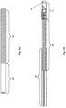
Fig. 1 is a partial fragmentary view of the imaging catheter in accordance with one embodiment. -
Fig. 2a is an enlarged portion of A ofFig. 1 , showing the distal end of the OCT imaging catheter in accordance with one embodiment; andFig. 2b is a cross-sectional view of the optical train. -
Fig. 3a is a side elevational, cross-sectional view of an embodiment of the monolithic distal tip and guidewire lumen of a monolithic catheter sheath; andFig. 3b is a side elevational, cross-sectional view of one embodiment of the monolithic catheter sheath representing background art for understanding the invention. -
Fig. 4 is a side, cross-sectional view of a distal end of one embodiment of the monolithic catheter sheath prior to forming the guidewire lumen. -
Fig. 5 is a perspective view of the monolithic catheter sheath depicting the sheath lumen and the guidewire lumen in phantom. -
Fig. 6a is a cross-sectional schematic view of one embodiment of the catheter monolithic outer sheath; andFig. 6b is a perspective view of one embodiment of the catheter monolithic outer sheath depicting the sheath lumen and the guidewire lumen and sheath lumen in phantom. -
Fig. 7a is a perspective view of one embodiment of the catheter monolithic outer sheath depicting the sheath lumen and the guidewire lumen in phantom; andFig. 7b is a perspective view of one embodiment of the catheter monolithic outer sheath depicting the sheath lumen and the guidewire lumen in phantom. -
Fig. 8a is a cross-sectional schematic view of one embodiment of the catheter monolithic outer sheath; andFig. 8b is a perspective view of one embodiment of the catheter monolithic outer sheath depicting the guidewire lumen and the optical train in phantom. -
Fig 9a is one embodiment of the rotary drive shaft; andFig. 9b is a perspective cross-sectional view of one embodiment of the rotary drive shaft. -
Fig. 10a is a side elevational view of an embodiment of the rotary shaft, andFig. 10b a side elevational view of an embodiment of the stranded hollow core shaft. -
Fig. 11a is a perspective view of a tube undergoing a bending force F,Fig. 11b . is a cross-sectional view of the catheter traversing a bend in a bode vessel; andFig. 11c is a cross-sectional view of the inner diameter (ID) and outer diameter (OD) of the hypotube. -
Fig. 12a and12b are graphs illustrating the torsion/bending ratio of one embodiment of the rotary drive shaft. -
Fig. 13 is perspective schematic view of the NURD mask for the catheter system. -
Fig. 14a is a recorded rectangular OCT images of a NURD mask for the catheter with moderate NURD, andFig. 14b is a graph of the angular position of the imaging beam versus time for one rotation, the X-axis (sample #) equals degrees in a single rotation of catheter inner member, and the Y-axis is the A-scan number where one full rotation corresponds to 1000 A-scans. -
Fig. 15a is a recorded rectangular OCT image of a NURD mask for a catheter with minimal NURD, and 15b is a graph of the angular position of the imaging beam versus time for one rotation, the X-axis (sample #) equals degrees in a single rotation of catheter inner member, and the Y-axis is the A-scan number where one full rotation corresponds to 1000 A-scans. -
Figs. 16a - 16c are polar OCT images of a NURD mask;Fig. 16a shows the catheter in a straight vessel where the NURD is small;Fig. 16b shows the catheter the NURD mask in a sharp 90 bend in the distal end where the NURD is small; andFig. 16c shows the catheter in a tortuous model LAD Co-Pilot within a tight valve and small NURD values. -
Figs. 17a - 17c are in vivo polar images recorded in a pig coronary artery placed with a stent demonstrating the simulated NURD effects in the same image. -
Fig. 18 is a schematic of thecatheter 10 is coupled to the proximal motor system. -
Fig. 19 is a graph of the angular position vs. rotational time. -
Fig. 20a is a cross section of the outer wall of the stationary sheath including a thickness S; andFig. 20b is the cross section of the outer wall of the stationary sheath with a geometrical image distortion when NURD is present. - The methods, apparatuses, and systems can be understood more readily by reference to the following detailed description of the methods, apparatuses, and systems, the non-limiting embodiments, and the accompanying figures.
- With particular reference to
Fig.1 , acatheter 10 is depicted comprising a monolithicouter sheath 20 including a central sheath lumen extending substantially the entire length of the monolithicouter sheath 20 and a monolithically formedflexible tip 28. The term "monolithic" or "monolithically formed" is without any joints or junctions formed by thermal, chemical or mechanical bonding. - The
catheter 10 construct for in vivo imaging, particularly, imaging of anatomical passageways, such as cardiovascular, neurovascular, gastrointestinal, genitor-urinary tract, or other anatomical luminal structures. Thecatheter 10 is coupled to an imaging modality, and in one embodiment the imaging modality is an Optical Coherence Tomography ("OCT") system. OCT is an optical interferometric technique for imaging subsurface tissue structure with micrometer-scale resolution. In another embodiment, the imaging modality is an ultrasound imaging modality, such as intravascular ultrasound ("IVUS), either alone or in combination with OCT imaging. The OCT system may include tunable laser or broadband light source or multiple tunable laser sources with corresponding detectors, and may be a spectrometer based OCT system or a Fourier Domain OCT system, as disclosed inU.S. Provisional Application 60/949,467catheter 10 may be integrated with IVUS by an OCT-IVUS catheter for concurrent imaging. As shown inFig. 1 , thecatheter 10 comprises the monolithicouter sheath 20 that houses an acoustical oroptical train 30. Theoptical train 20 includes a length of d, and thecatheter 10 includes a length of D from the distal portion of theFORJ 60 to the distalmonolithic tip 28 of the catheter monolithicouter sheath 20. In use, theoptical train 30 rotates under the influence of an external rotary drive motor (not shown) coupled to arotary drive shaft 40 and anoptical fiber 50 through a Fiber Optic Rotary Junction 60 ("FORJ"), thereby also rotating theoptical train 30. Therotary drive shaft 40 includes a drive shaft lumen, through which theoptical fiber 50 is concentrically or coaxially disposed. - As shown in
Fig. 1 , a plug-inconnector 62 is coupled to the proximal end of therotary drive shaft 40, to couple thecatheter 10 to the rotary drive motor. The plug-in connector may include a Subscription Channel (SC) - Angled Physical Contact (APC) connectors to ensure lower insertion loss and back reflection. TheFORJ 60 may include fiber pigtail, ST, FC, SC, FC/UPC receptacles, or any combination receptacles on the rotor or the stator side (Princetel, Lawrenceville, NJ). Alternatively, theconnector 62 may include a centering boot to center the optical fiber with respect to therotary drive shaft 40. The centering boot includes a first lumen to accept the optical fiber and a second lumen to accept therotary drive shaft 40. The FORJ is provided to permit rotation of the optical fiber and rotary shaft while maintaining optical communication with the radiant light source (e.g., tunable laser or broadband emitter) with minimal insertion loss and return loss performance. The rotary drive motor imparts rotational movement to therotary drive shaft 40 either by a DC brushless motor and the like. The rotary drive motor may rotate at revolutions per minute (RPM) for a 360 degree rotation of therotary drive shaft 40. A linear pull back mechanism may also be coupled to the rotary drive shaft, which may include a stepping motor. The monolithicouter sheath 20 is held stationary, relative to therotary drive shaft 40, by use of a permanently affixed retainingbead 42 that is connected to the frame of the rotary drive motor. The bead includes a first lumen and a second lumen smaller than the first lumen, whereby the second lumen communicates through the first lumen. In one embodiment, the bead is a single machined aluminum part that is attached to the monolithicouter sheath 20 by means of mechanical thread engagement and adhesive. - The
rotary drive shaft 40 is concentrically or coaxially positioned within the central lumen of the monolithicouter sheath 20 and substantially extends along the longitudinal length D of the central lumen. Coaxially engagement between therotary drive shaft 40 and the central lumen of the monolithicouter sheath 20 may be accomplished with the OD of therotary drive shaft 40 matching the ID of the monolithicouter sheath 20 or varying the OD of the rotary drive shaft to the ID of the monolithicouter sheath 20. Therotary drive shaft 40 terminates at its distal end in proximity to the distal end of the central lumen adjacent the proximal end of thecatheter 10. Theoptical train 30 is carried by therotary drive shaft 40, with theoptical fiber 50 running the length of therotary drive shaft 40 through the drive shaft lumen. Therotary drive shaft 40 permits transmission of torque from the rotary motor to theoptical train 30 along the entire length of the catheter shaft. As such, therotary dive shaft 40 includes having sufficient torsional rigidity or torqueability and lateral flexibility or flexion to navigate potentially tortuous anatomical pathways while minimizing NURD to ensure accurate imaging. Torqueability is the ability of the rotary drive shaft to be turned or rotated while traversing bends or turns in the patient's vasculature. - In one embodiment, the
rotary drive shaft 40 includes a hypotube metal over a proximal portion or the entire proximal section of therotary drive shaft 40. Alternatively, representing background art for understanding the invention, therotary drive shaft 40 includes a stranded hollow core shaft extending the substantial length of therotary drive shaft 40. The stranded hollow core shaft may comprise a plurality of helically wound wire strands so that mechanical rotation of the rotary drive shaft is in the same direction as the helical wire strands. The stranded hollow core shaft may include an inner stranded drive shaft and outer stranded drive shaft, where in outer stranded drive shaft is wound in the opposite helical direction than the inner stranded drive shaft. Aprotection bearing 70 may be coupled to either the stranded hollow core shaft or the hypotube metal. The stranded hollow core shaft, the hypotube metal, or a combination thereof provides sufficient lateral flexibility to ensure access through highly tortuous passageways, such as the aortic arch and coronary arteries. In another embodiment, the hypotube metal is concentrically or coaxially fitted over a proximal portion or the entire proximal section of the stranded hollow core shaft. The coaxial fitting of the hypotube metal over the stranded hollow core shaft may be accomplished by allowing the OD of the stranded hollow core shaft to vary from the ID of the hypotube metal tube by about 0.0254 to 0.2286 mm (0.001 to 0.009 inches). In this manner the highly flexible stranded hollow core shaft lessens NURD by the relatively less flexible hypotube metal at the more distal end of the catheter to permit greater distal end flexion or lateral flexibility. While maintaining flexibility, the rotary drive shaft also maintains the pushability, the ability of the catheter to be efficiently and easily pushed through the vasculature of the patient without damage to the catheter or patient, getting blocked, kinked, whipped, etc. - In accordance with another embodiment, the
rotary drive shaft 40 includes a shortened hypotube metal shaft attached in a generally overlapping attachment with a section of stranded hollow core shaft, with there being a very slight mismatch in the outer diameters between the hypotube metal and the stranded hollow core shaft to permit concentric or coaxial engagement and attachment between the respective end sections. Alternatively, the hypotube metal and the stranded hollow core shaft may have generally the same outer diameter to permit end-to-end connection, such as a butt weld there between. The stranded hollow core shaft includes single layer uni-directional and multi-layer directional winding configurations when coupled to the hypotube metal shaft. - In one embodiment of the monolithic
outer sheath 20, at least a portion of the monolithic outer sheath is fabricated of an optically transparent polymer, such as, for example, perfluoroalkoxy (PFA) polymer, polytetrafluoroethylene (PTFE) partially covered with a polyether block amide (Pebax®) at the distal end, or tetrafluoroethylene and hexafloropropylene co-polymer (FEP). The optically transparent polymer is transparent in the spectral region of light being used for imaging. Similar biocompatible optically transparent polymers having similar properties of lubricity, flexibility, optical clarity, biocompatible and sterilizability may alternatively be employed to form the catheter shaft. In accordance with one embodiment, FEP is used to fabricate the catheter sheath. The catheter sheath is fabricated in a monolithic manner such that the central lumen terminates at the atraumatic monolithic tip without any intervening joints. Atraumatic is not producing injury or damage. As shown inFig. 2a , a rapidexchange guidewire lumen 22 is formed entirely within the atraumatic monolithic tip with both the proximal guidewire port and the distal guidewire port accessing the guidewire lumen distal the termination of the central lumen of the catheter sheath. The guidewire is the thin wire over which the catheter rides. - As shown in
Fig. 2a , aguidewire lumen 22 is formed in the distal portion of the monolithicouter sheath 20, while acentral sheath lumen 32 extends proximally from the distal portion of the monolithicouter sheath 20. Theguidewire lumen 22 includes aguidewire exit 24 and aguidewire entrance 26. Theguidewire lumen 22 is positioned entirely in the distal terminus of thecentral sheath lumen 32 such that the guidewire (not shown) may be rapidly exchanged and does not interfere with the rotational movement of theoptical train 30,rotary drive shaft 40 or the protection bearing 70 within the central lumen of thecatheter sheath 20. - In accordance with a another embodiment, the
rotary drive shaft 40 includes theprotection bearing 70, which houses the distal end optics or distal end acoustics at the distal end of thecatheter 10, as shown inFig. 2b . Theprotection bearing 70 may be coaxially mounted over the distal end optics, or alternatively, molded over the distal end optics or the distal end optics molded into theprotection bearing 70. Theprotection bearing 70 may include a diameter to coaxially engage the distal end optics to ensure a 1:1 rotation of the protection bearing 70 with the distal end optics. In one embodiment, theprotection bearing 70 may include a Platinum/Iridium tube and is formed with anopening 92. The opening may be positioned in optical alignment with theprism 90 in order to permit light to pass through theopening 92 and optically communicate with the sample being imaged, as shown inFig. 2b . The Platinum/Iridium tube may comprise about 75-97 % Pt and about 3-25% Ir, which provides radiopacity. Alternatively, the metal hypotube of the rotary drive shaft replaces theprotection bearing 70, where the metal hypotube extends coaxially over the distal end optics and includes an opening for the distal end optics. Alternatively, theprotection bearing 70 may include other metals nitinol, i.e. nickel titanium alloy, or another pseudometallic biocompatible alloy such as stainless steel, tantalum, gold, platinum, titanium, copper, nickel, vanadium, zinc metal alloys thereof, copper-zinc-aluminum alloy, and combinations thereof, with radiopaque markers in order to provide visible reference points. Alternatively, theprotection bearing 70 may include an epoxy rounded tip to ensure smooth rotational translation of theprotection bearing 70. Alternatively, theprotection bearing 70 includes abearing plug 74 within the distal portion of the protection bearing's distal lumen. The bearing plug 74 may coaxially fit into the distal portion of theprotection bearing 70, or may be secured by adhesive, welding, and the like. The bearing plug 74 may include a metal material, alternatively a metal/polymer material, alternatively stainless steel. - In accordance with one embodiment, the
optical train 30 includes the monolithicouter sheath 20 theoptical fiber 50 in association with therotary drive shaft 40, the protection bearing 70 housing a ferrule/gradient index lens ("GRIN")assembly 80 at a distal end of theoptical fiber 50, as shown inFig. 2a . The ferrule/GRIN assembly 80 optically coupled to aprism 90 or mirror to conduct light between theoptical fiber 50, ferrule/GRIN assembly and the sample being imaged. The distal end of theoptical train 30, i.e., the distal endoptical fiber 50, the ferrule/GRIN lens assembly and theprism 90, are all secured within theprotection bearing 70 and rotate with theprotection bearing 70, under the influence of therotary drive shaft 40, within thecentral lumen 32 of thecatheter sheath 20. In use, theoptical train 30 rotates under the influence of an external rotary drive motor coupled to the rotary drive shaft and optical fiber through theFORJ 60, thereby also rotating the ferrule/GRIN lens 80 assembly and theprism 90 to emitoptical energy 94 at an angle and through 360 degrees around the monolithicouter sheath 20. - As shown in
Fig. 2b , the ferrule/GRIN assembly 80 includes aGRIN lens 82 and aferrule 84. Theoptical fiber 50 may include a core, cladding and buffer and is optically coupled to theferrule 84. Theferrule 84 is optically coupled to theGRIN lens 82 andprism 90 to transmit light between theoptical fiber 50,GRIN lens 82 and the sample being imaged. Theferrule 84 at a distal end of theoptical fiber 50 supports and terminates the distal end of theoptical fiber 50, where theoptical fiber 50 may be coaxially fitted within theferrule 84. The ferrule may include a lumen and a tapered cladding to coaxially couple the core of theoptical fiber 50. When theoptical fiber 50 core is coupled with theferrule 84, thefiber 50 may not include the buffer. Theoptical fiber 50 may be potted or adhesively secured to theferrule 84 atpoint 86 with optical glue, curing adhesive, and the like, as to provide a coaxial alignment of the optical fiber and the ferrule. TheGRIN lens 82 is optically coupled to a distal surface of theferrule 84 atpoint 88, such as by optically transparent adhesive. TheGRIN lens 82 and theferrule 84 may include an angled engagement, where the angle offset of the distal end of theferrule 84 matches the angle offset of the proximal end of theGRIN lens 82. The prism ormirror 90 is optically coupled to the distal surface of theGRIN lens 82 atpoint 98, such as by optically transparent adhesive. The distal surface of theGRIN lens 82 may include an angled offset. Theprism 90 may include a right angled prism and the prism angles may be constructed to provide balancing of astigmatism introduced by the sheath. An optical pathway is formed along the longitudinal axis of therotary drive shaft 40, thecatheter sheath 20, andprotection bearing 70. The prism ormirror 90 serves to redirect at least some portion of the light away from the central longitudinal axis and generally radially outward, through the optically transparent portion of the monolithicouter sheath 20 to communicate with the body tissue being imaged throughout 360 degrees. - Some of the incident light may not be redirected radially outward. The prism angles may be constructed to provide a balancing of astigmatism introduced by the catheter sheath. The incident light may not necessarily all be used for imaging, where additional optical energy beams are for therapeutic purposes or possibly some other energy source.
- As shown in
Fig. 3a representing background art for understanding the invention, the monolithicouter sheath 20 may include anouter layer 110 and aninner layer 120 to form alaminate structure 100. Theouter layer 110 may be constructed of Pebax® extending the substantial length along the proximal portion of the catheter sheath and theouter layer 110 provides greater structural rigidity relative to theinner layer 120. Theinner layer 120 may be constructed of PTFE, with the PTFEinner layer 120 extending distally from the Pebax®outer layer 110 and forming the most distal section, which is optically transparent and flexible to permit optical communication to the sample and greater traversability for the catheter during insertion or retraction within the anatomical passageway. Alternatively, various other materials, such as FEP, could be used in place of PTFE in the given example.Fig. 3b representing background art for understanding the invention shows the solid monolithically formedtip 28 and abase layer 130 and atop layer 140. Thebase layer 130 maybe constructed of Pebax® substantially along the base of the catheter sheath and provides greater structural rigidity relative to thetop layer 140. The greater structural rigidity allows the monolithic outer sheath greater pushability along the proximal portion of the monolithic outer sheath. Alternatively, thebase layer 130 may include aplug 132. Theplug 132 may include a space between theprotection bearing 70 when theprotection bearing 70 engages with the monoliticouter sheath 20. Theplug 132 may include an angled engagement with distal portion of the sheath lumen to impart increased flexibility to the distal end of the monolithicouter sheath 20. Theplug 132 may include polymeric material, including, but not limited to PTFE, FEP, and the like. Thetop layer 140 may be constructed of PTFE, with thePTFE top layer 140 extending distally from the Pebax® base layer 130, which provides greater flexibility along the distal end of the monolithic outer sheath for navigating tortuous pathways. Alternatively, the layers of themonolithic sheath 20 include a coating either on the outer layers or inner layers for smooth transitioning and less friction during navigation. Such coatings may be biocompatible, polymeric, saline, and the like. -
Fig. 4 depicts the monolithicouter sheath 20 prior to theguidewire lumen 22 being formed. In one embodiment, the solid monolithically formedtip 28 is formed by first providing a tubularcatheter sheath precursor 150, preferably placing a forming mandrel in thecentral sheath lumen 152 of the tubularcatheter sheath precursor 150, then thermoforming the solid tip 154 into a desired shape. Thermoforming is any process of forming thermoplastic sheet, which consists of heating the sheet and forcing it onto a mold surface. The sheet or film is heated between infrared, natural gas, or other heaters to its forming temperature, then it is stretched over or into a temperature-controlled, single-surface mold. The sheet is held against the mold surface unit until cooled, and the formed part is then trimmed from the sheet. There are several categories of thermoforming, including vacuum forming, pressure forming, twin-sheet forming, drape forming, free blowing, simple sheet bending, and the like. The shape of themonolithic tip 28 maybe rounded, radiused, tapered, or generally frustroconical with an atraumatic distal end formed. A radiused tip includes an angle of curvature that is derived from the radius of the outer sheath OD, where the angle or degree of curvature equals the reciprocal of the radius (1/R). - The
guidewire lumen 156, as shown in phantom depicted inFig. 5 may then be formed by bending the soliddistal tip 28 and drilling a straight hole angularly through the distal end and to a lateral side of the distal tip, then releasing the bend in the tip to provide distal end and proximal side guidewire ports and a curved lumen. Alternatively, the tip may be formed with theguidewire lumen 156 during the thermoforming process by providing the appropriate mold. The resultingguidewire lumen 156 may or may not maintain a straight longitudinal axis, where the longitudinal axis runs along the x-axis of thesheath 20, as shown in phantom inFig. 5 . In one embodiment, theguidewire lumen 156 includes a straightlongitudinal axis 160 and anon-longitudinal axis 162. The straightlongitudinal axis 160 is included for some length along the distal portion of the catheter sheath body and associated with theguidewire entrance 162. Thenon-longitudinal axis 162 is included for some length along the proximal portion of the catheter body and is associated with theguidewire exit 164. The angled measurements for thenon-longitudinal axis 162 near the guidewire exit can be any angle relative to thelongitudinal axis 160 as to provide for the rapid exchange of the guidewire and no kinking or whipping of the guidewire. In one embodiment, the angle or degree of curvature for the non-longitudinal axis relative the longitudinal axis is about 0.1 to 10 degrees, about 1 to 8 degrees, or about 1.5 to 6 degrees. - The monolithic
outer sheath 20 includes the absence of or potential for uneven surfaces that may irritate or damage tissues in anatomical passageways or interfere with the guiding catheter during retraction or advancement of the catheter, the absence of joints which could separate and dangerously embolize, and the absence of joints which could leak fluid into or out of the sheath. Because of its monolithic construction, the central lumen of the outer catheter sheath may be filled with a fluid that could serve to (a) provide lubrication between the monolithic outer sheath and the rotary shaft, (b) reduce optical astigmatism originating from the cylindrical curvature of the inner sheath surface due to the lower index of refraction mismatch of liquid when compared with air, (c) provide additional column strength and kink resistance to the catheter, (d) viscously dampen NURD, or (e) provide negative torsional feedback to stabilize or dampen non-uniformities in rotation. - The monolithic design of the catheter outer sheath and the monolithic atraumatic tip further permit different engineering of material properties along the length of the monolithic outer sheath. For example, the durometer of the catheter sheath may be varied along the length of the catheter sheath during manufacture of the sheath precursor material; the inner and/or outer diameter of the catheter sheath may be made to vary, such as by tapering, along the length of the continuous monolithic tube; the wall thicknesses of the catheter sheath and the concomitant flexibility profiles may be varied along the longitudinal length of the catheter sheath, or the catheter sheath may be variably reinforced to alter the flexibility profiles along the longitudinal axis of the catheter sheath, such as by applying a braiding material, a concentric reinforcement, such as another overlaid tube, or combinations of the foregoing. The braiding material may be a polymer formed from conventional braiding machines. The durometer is the hardness of the material, as defined as the material's resistance to permanent indentation. The two most common scales, using slightly different measurement systems, are the ASTM D2240 type A and type D scales. The A scale is for softer plastics, while the D scale is for harder ones. However, the ASTM D2240-00 testing standard calls for a total of 12 scales, depending on the intended use; types A, B, C, D, DO, E, M, O, OO, OOO, OOO-S, and R. Each scale results in a value between 0 and 100, with higher values indicating a harder material.
- Another embodiment of the
monolithic catheter sheath 200 is shown inFig. 6a . Themonolithic catheter sheath 200 includes asheath lumen 210, aguidewire lumen 220, and a monolithicatraumatic tip 230. Thesheath lumen 210 includes a roundeddistal end 212 for the placement of theoptical train 30. Thesheath lumen 210 includes a longitudinal axis substantially along the x-axis direction of themonolithic catheter sheath 200. Theguidewire lumen 220 includes aguidewire exit 222, aguidewire entrance 224, and adistal marker band 226. Thedistal marker band 226 is of a radiopaque material. Theguidewire lumen 220 includes adiameter 236, which may remain constant along the longitudinal length of theguidewire lumen 220. The longitudinal axis of theguidewire lumen 220 is at a slight angle A and offset from the longitudinal axis of thesheath lumen 210. The offset angle A may be about 1 to 20 degrees, from about 1 to 5 degrees, and from about 2 to 4 degrees The offset angle A minimizes space between the guidewire and the catheter body, which helps to minimize chance of the guidewire getting entangled when crossing stents. Thecatheter sheath 200 also includes abuffer 240 of solid material betweenguide wire lumen 220 and thesheath lumen 210 to prevent the passage of fluid and offset theguidewire lumen 220 from thesheath lumen 210. Theguide wire lumen 220 is approximately straight along its longitudinal axis, as to permit free passage of guide wire (not shown). Theguidewire lumen 220 includes aguidewire lumen wall 228 that includes at least two thicknesses. In one embodiment, theguidewire lumen wall 228 includes afirst thickness 232 near theguidewire exit 222 slightly larger than asecond thickness 234 near theguidewire entrance 224. Theguidewire lumen wall 228 first thickness nearguidewire exit 222 evenly distributes strain on themonolithic catheter sheath 200 and prevents kinking of the guidewire at theguidewire exit 222. An outer transparent view of themonolithic catheter sheath 200 is shown inFig. 6b , showing thesheath lumen 210 andguidewire lumen 220 in phantom. - As shown in phantom in
Fig. 7a , in another embodiment of themonolithic catheter sheath 200, a flushingport 250 is coupled to thesheath lumen 210 and the exterior of thecatheter sheath 200. The flushingport 250 between thesheath lumen 210 and the exterior of thecatheter sheath 200 allows an operator to flush air or any fluid out of thesheath lumen 210. Themonolithic catheter sheath 200 may use standard luer connections at the proximal end of thecatheter sheath 200 to provide the flushing fluid. Luer connection systems are the standard way of attaching catheters, IV tubes, and so on to each other, and they consist of round male and female interlocking tubes, slightly tapered to hold together better with even just a simple pressure/twist fit. Luer connections can either be a luer slip, or can have an additional outer rim of threading. Alternatively, the embodiment of themonolithic catheter sheath 200 includes a flushingport 252 coupled to theguidewire lumen 220 and thesheath lumen 210 to allow the operator to flush air or fluid out of thesheath lumen 210, as shown in phantom inFig. 7b . - Another embodiment of the
monolithic catheter sheath 300 is shown inFig. 8a . Themonolithic catheter sheath 300 includes asheath lumen 310, aguidewire lumen 320, and aplug 330. Thesheath lumen 310 includes a longitudinal axis substantially along the x-axis of themonolithic catheter sheath 300. The sheath lumen 310 houses the protection bearing 312 coupled to thedrive shaft 314 and theOCT imaging port 316. Theguidewire lumen 320 includes aguidewire exit 322, aguidewire entrance 324, and acurvature 326 offset lumen. The distal portion of theguidewire lumen 320 includes a longitudinal axis along the x-axis of thecatheter sheath 300. Thecatheter sheath 300 also includes aplug 330 of solid material betweenguidewire lumen 320 and thesheath lumen 310 to prevent the passage of fluid and offset theguidewire lumen 320 from thesheath lumen 310. Thecurvature lumen 326 is offset from the distal longitudinal axis of the guidewire lumen and the longitudinal axis of thesheath lumen 310. Thecurvature 326 offset minimizes space between the guidewire (not shown) and the monolithic catheter body, which helps to minimize the wire entangling when crossing stents and tortuous pathways. An outer transparent view of themonolithic catheter sheath 300 embodiment is shown inFig. 8b , with thesheath lumen 310, theguidewire lumen 320, and thecurvature lumen 326 in phantom. - Turning now to
Figures 9-11 , alternative embodiments of therotary drive shaft 40 are illustrated. As discussed above, therotary drive shaft 40 connects the distal end optical train and optics to the rotary motor and the transmission of rotary torque to the distal end optics while minimizing NURD. As shown inFig. 9a , therotary drive shaft 40 may comprise entirely of a hypotubemetal drive shaft 400, a strandedhollow core shaft 500 or a combination of the hypotubemetal drive shaft 400 joined with the strandedhollow core shaft 500, or alternating combinations of the hypotubemetal drive shaft 400 and strandedhollow core shaft 500. The hypotube metal drive shaft may comprise nitinol, i.e. nickel titanium alloy, or another pseudometallic biocompatible alloy such as stainless steel, tantalum, gold, platinum, titanium, copper, nickel, vanadium, zinc metal alloys thereof, copper-zinc-aluminum alloy, and combinations thereof. Alternatively, themetal hypotube shaft 400 may include a reinforced telescoping inner assembly coaxially coupled over the proximal end of themetal hypotube shaft 400. The reinforced telescoping inner assembly is stronger than themetal hypotube shaft 400 to prevent buckling, bending, or shearing. The reinforced telescoping inner assembly includes a metal tube stainless steel design coupled to the centering boot to permit longer push-forward capability and provide improved liquid seal during flush. - As shown in
Fig. 9b , the strandedhollow core shaft 500 comprises a stranded hollow core orlumen 510 including a plurality of helically woundmetal wires 520. The helically woundmetal wires 520 include an outer surface and a diameter, which may exist at about 0.005 to about 0.0127 cm (about 0.002 to about 0.005 inches). The helicalwound metal wires 520 are fixedly engaged with neighboring metal wires on their respective outer surfaces. The fixed engagement of the helicalwound metal wires 520 completely encases the strandedhollow lumen 510. The strandedhollow core shaft 500 with the helicalwound metal wires 520 are different from a spring coil wire, in that a spring coil wire consists of a single metal wire wound about itself in a helical fashion. The helically woundmetal wires 520 may exist in any number to form the strandedhollow core shaft 500, in one embodiment from about 2 to 15 wires, from about 3 to 12 wires, or from about 4 to 10 wires in the helical configuration. An individualhelical wound wire 520 may consist of only one metal filament; however, the individualhelical wound wire 520 may include more than one metal filament. The helically woundmetal wires 520 may comprise nitinol, i.e. nickel titanium alloy, or another pseudometallic biocompatible alloy such as stainless steel, tantalum, gold, platinum, titanium, copper, nickel, vanadium, zinc metal alloys thereof, copper-zinc-aluminum alloy, and combinations thereof. The strandedhollow core shaft 500 may be helically wound and that portion may consist of an inner helical stranded portion and an outer helical stranded portion. The inner helical stranded portion may wind in the opposite direction as the outer helical stranded portion. In one embodiment, the strandedhollow core shaft 500 may include a helical wound configuration including a Picks Per Centimeter (PPC), where there may be about 1.97 to 5.91, about 2.76 to 4.72 PPC and about 3.15 to 3.94 PPC (Picks Per Inch (PPI), where there may be about 5 to 15, about 7 to 12 PPI, and about 8 to 10 PPI) for the helical configuration. The helical wound configuration may have alternating symmetries along the longitudinal axis of the rotary drive shaft, such as an infinite helical symmetry, n-fold helical symmetry, and non-repeating helical symmetry. The strandedhollow core shaft 500 may be coated with some biocompatible material, such as PTFE or similar polymers to provide lubricity within the monolithic catheter sheath. - The distal part of the
rotary drive shaft 40 may be the strandedhollow core 500 design, where flexibility is required at the entry point to the body. From the proximal portion to the distal portion of therotary drive shaft 40, a single layer or double layer wound stranded hollow core may be included at the proximal portion, a hypotubemetal drive shaft 400, and a single layer or double layer wound at the distal portion as to have a flexible distal tip. - The hypotube
metal drive shaft 400 may include a solid wall extending substantially the entire longitudinal length of the central lumen of therotary drive shaft 40 in combination with the strandedhollow core shaft 500, which (a) increases torsional rigidity of the rotating shaft and reduces NURD; (b) increases column strength or axial rigidity to improve the pushability of the catheter assembly; (c) reduces or eliminates the possibility of the stranded or coiled hollow core shaft unraveling or disassociating under the torsional forces applied; (d) improves the frictional interface by replacing an interrupted or more concentrated load transference between individual strands and the monolithic outer sheath with a continuous and more distributed load across the solid-walled hypotube metal shaft; and (e) the hypotube metal shaft offers a good fluid seal against the monolithic outer sheath over the proximal section of a fluid-filled catheter due to the solid-walled design. - The solid-walled hypotube
metal drive shaft 400 may, alternatively be used in conjunction with the stranded hollow core shaft by either butt-joining a distal end of thehypotube metal shaft 400 onto a proximal end of the strandedhollow core shaft 500, as illustrated inFig. 10a . The butt-joining of the two ends may be accomplished by welding or adhesives to ensure little to no vibration during rotation. Alternatively, a portion of thehypotube metal shaft 400 may be concentrically or coaxially engaged or fitted with a portion of the strandedhollow core shaft 500, as is illustrated inFig. 10b . The coaxial fitting ensures a 1:1 rotation of thehypotube metal shaft 400 and the strandedhollow core shaft 500 to ensure little to no vibration during rotation. The strandedhollow core shaft 500 is coaxially engaged with theprotection bearing 70, where the protection bearing may include an epoxy roundedtip 72 to ensure smooth rotational translation of theprotection bearing 70. - Longer sections of the
hypotube metal shaft 400 may be employed proximal of therotary drive shaft 40 to achieve a greater reduction of NURD. Due to its relative rigidity, the length of thehypotube metal shaft 400 should not extend too far distally so as to interfere with the distal flexibility of the catheter and prevent it from navigating tortuous anatomical passageways. The wall-thickness of thehypotube metal shaft 400 may be varied along its length to impart variable stiffness along the longitudinal axis of thehypotube metal shaft 400. In this manner, relatively thinner wall-thicknesses may be formed distally than those formed more proximally, to impart greater flexibility at the distal end of thehypotube metal shaft 400. The wall thickness may be varied by extrusion processing, mechanical means, such as grinding, abrasive blasting, turning, by chemical or electrochemical means, such as electro-polishing or etching, or by combinations of the foregoing. Alternatively, slots, holes or other aperture shape formations may be formed by means of cutting, etching, ablating or other means to generate designs in the tubular structure which permit additional flexibility of the distal region of thehypotube metal shaft 400 while retaining substantial torsional rigidity. - The
rotary drive shaft 40 design can include the following considerations: (1) the material type and geometry of the material that comprise a given segment; and (2) a number of distinct material segments when progressing from the proximal to distal portions of the catheter. - In one embodiment, the design of the
rotary drive shaft 40 includes setting the lateral flexibility of the material at the proximal end to a specific point and increasing the lateral flexibility from the proximal end to the distal segments of the rotary drive shaft. Generally speaking, a higher lateral flexibility is desired in portions of the catheter that experience the greatest geometric curvature when used for imaging. In addition, the diameter of the rotary drive shaft may become gradually or stepwise smaller from the proximal end to the distal portions of the rotary drive shaft. By reducing the wall thickness or by reducing the ID and OD or both the ID and OD, the diameter of the rotary drive shaft becomes smaller. The geometry of catheter at the surgical entry point and the geometry of the human coronary tract generally put these regions at the surgical entry point to the body and the aortic arch and the coronary blood vessel being interrogated. - The material type and the geometry of the materials in a given segment may vary in the rotary drive shaft. Different geometries are recognized for a given segment of the rotary drive shaft. Examples include, but are not limited to: (1) homogeneous solid (e.g., nitinol, PEEK, or some polymer); (2) stranded hollow core shaft (single wound, double counter-wound, or triple coil-wound or generally multiple wound); (3) braided multi-stranded hollow core shaft; (4) fibrous composite (fibers in a matrix); (5) patterned solid (#1 with patterned holes or apertures); and (6) patterned composite (#4 with patterned holes or apertures).
- In one embodiment, the number of distinct segments may vary. A two segment rotary drive shaft includes the metal hypotube shaft in the proximal portion and a stranded hollow core 5 at the distal portion. The joints between any segments may be joined end-to-end with for example a butt-couple, weld, epoxy or other jointing technique. Alternately, an overlapping style of joint may be used, i.e. male-female joints, or by coaxial engagement, concentric alignment, and the like. Connection of the segments of an overlapping style of joint may be accomplished by means of welding, adhesive, or over-molding given that at least one element is polymer.
- In addition, a gradation, either gradual or stepwise, may be accomplished by a change in material properties along the length of the rotary drive shaft. For example, the material properties may be adjusted such as the modulus of elasticity of the material via methods including, but not limited to annealing, carburization, or heat treat and subsequent quenching techniques. In the case of nitinol, one may adjust the transition temperature (Af) along the length by means of heat treatment, cold working, or some combination thereof. Mf is the temperature at which the transition to Martensite is finished during cooling. Accordingly, during heating As and A1 are the temperatures at which the transformation from Martensite to Austenite starts and finishes. Nitinol is typically composed of approximately 50 to 55.6% nickel by weight. Making small changes in the composition can change the transition temperature of the alloy significantly. For this reason, nitinol may or may not be superelastic at certain temperatures, thus allowing the modulus of elasticity to be adjusted according to the temperature of use.
- Generally speaking, the angular deflection (θ) for NURD in a homogenous hollow tube including a cross section is given by Equation (1):


- The change in the angular velocity (i.e. the second derivative and angular deflection) is given by the following:


- The bending load, as shown in
Fig. 11a , is generally M = Fl, where M = the bending morphology, F is the Force (load on the tube), and l is the length. The Section modulus (S) is given by the equation S = I/C, and I is given by Equation (4):

- The bending state σ = M/S can be rewritten as:

- The reduction of Sσ/l or the reduction of F will reduce the load. Alternatively, the load can be reduced by reducing the friction, which is dependent upon the material coefficient and force by equation (6):

- As shown in
Fig. 11b , the catheter, at any bending point in avessel 600, there will be several friction points 610. Friction is a function of the normal force (N) between the drive shaft and the inner wall of the outer sheath, so then the bending moment is related to friction by the section modulus as follows: Friction force Fk = µkN, Normal force


- Reducing the diameter (d) reduces


- By using Equation (8) and substituting Fk for F results in:


- By substituting T and J into


- The two competing mass moment of inertia terms are J and I. The two opposing factors are friction due to bending and torsional rigidity. Moment of inertial (I) from the section modulus in the bending portion is compared to the polar second moment of area (J).
- For a hollow circular cross section, J = π/32 (do 4-di 4),

Fig. 11c , do is the outer diameter of the tube, di is the inner diameter of the tube, and d is the diameter from the midsection of the tube. Substituting in terms of (do+di)/2 gives:

- Comparing equation (12) and (13) by varying inner diameter (ID) from about 2.79-0.609 mm (0.11- 0.024 inches) and the outer diameter (OD) from about 0.38-0.63 mm (0.015-025 inches), and holding OD constant at 5.08 mm (0.200 inches) and 0.63 mm (0.025 inches) produces the graphs as illustrated in
Figs. 12a and12b . -
Fig. 12a is a chart illustrating theTorsion Term 620 and theBending Term 622.Fig. 12b is a chart illustrating the change in the Torsion/Bending Ratio 630 while measuring for NURD during angular deflection testing of the rotary drive shaft within an outer monolithic sheath. The characteristics of the rotary drive shaft and/or the outer monolithic sheath may be tested from various mechanical testing methods, such as tensile tests, torsion test, bending test or compression test. The torsion and bending tests provide useful information about the type of deformation of the rotary drive shaft and catheter monolithic sheath to account for NURD. - The measurement of rotary position of the
catheter 10 may be used as input for a NURD-reduction software approach. As shown inFig. 18 , thecatheter 10 is coupled to theproximal motor system 700, including atorque sensor 710, arotary motor 720, alinear motor 730, and a computer/software program 740 operably coupled to themotor system 700. The method for estimating NURD in therotational imaging catheter 10 is by measuring the torque on proximale end of thecatheter 10 with thetorque sensor 710. If NURD is characterized (e.g, in the form of an equation or data points representing angular position of imaging transducer vs. time) then removal of or correcting for NURD via post-processing of the image is straightforward. To truly characterize NURD, the angular position of the rotating imaging transducer must be known. - Methods for determining this position include active approaches such as distal accelerometers or passive approaches such as encoding a circumferential line pattern in the catheter outer sheath which can be detected within the image itself (OCT, IVUS, etc.) or encoding the catheter sheath thickness into the angular position and detecting within the OCT or IVUS image. An active method for estimating the angular position of the rotating imaging transducer as a function of time (i.e. rotational period) by measuring the slight variation in torque required to drive the catheter through one period of rotation (2π).
- The proximal torque measurement is indirect because measurements are made on the proximal end of the driveshaft, however the torsional properties of the driveshaft are known and constant, and thus the mechanical response of the distal tip can be estimated by the mechanical response of the proximal shaft. Knowledge of the angular position vs. time is shown in
Fig. 19 , and is an important input to correct for NURD. The y-axis of the graph inFig. 19 is the rotational time, where 1 rotation has occurred. - A passive method for indirectly determining the angular position of the
rotating imaging transducer 750 as a function of time (i.e. rotational period) is by forcing the rotating transducer to be in an eccentric location with respect to the outer wall of the stationary sheath. - As shown in
Fig. 20a , the outer wall of thestationary sheath 752 can be visualized in the image and because it is eccentric with respect to the transducer rotation. Theouter sheath 752 includes a thickness S. The outer wall of the stationary sheath will experience a geometrical image distortion (i.e. the apple-like cross-sectional shape) when NURD is present and the catheter is not centered on the vessel axis, as shown inFig. 20b . The eccentricity of the rotating portion with respect to theouter sheath 752 must only be large enough to visualize in the image (i.e. the difference in wall thickness as a function of angle due to the eccentricity must be larger than the depth resolution of the imaging modality). - To create a representation of angular position vs. rotational period, the image of the
outer sheath 752outer diameter OD 754 and the wall thickness S is compared to the a priori known eccentricity of the sheath. This comparison can be based on curve fitting to analytical models, statistical decision tree, or other numerical methods. The method for determining the thickness data from the angular position of a sensor within a catheter having a sheath wall of varying thickness can be found inU.S. Patent No. 6,450,964 . - The beam distortion (e.g. astigmatism) from the eccentrically oriented sheath will be minimal because the wall thickness vs. angle can be small relative to the beam diameter as it passes through the sheath. This can be further minimized by matching the wave speed in the sheath material with the fluid media bordering the ID and OD of the sheath (i.e. refractive index if OCT, acoustic impedance if ultrasound).
- The following examples are put forth so as to provide those of ordinary skill in the art with a complete disclosure and description of how the articles, devices, systems, and/or methods claimed herein are made and evaluated, and are intended to be purely exemplary and are not intended to limit the scope of articles, systems, and/or methods. Efforts have been made to ensure accuracy with respect to numbers (e.g., amounts, temperature, etc.), but some errors and deviations should be accounted for.
- OCT images of a NURD mask for the catheter with a vessel in phantom are shown in
Figs. 14 ,15 , and16 . The examples span the range from mild to moderate NURD with for each case the angular position vs. time and the resulting B-scan profile. The catheter OCT system records 1000 A-lines per rotation. A tube called a resolution mask orNURD mask 650 is placed over the catheter system, as shown inFig. 13 . TheNURD mask 650 may include several different sizes to measure the effects of NURD at different diameters. The NURD mask includes a plurality ofslots 652, where the widths of the slots may range from about 0.157 to about 0.314 mm. Theslots 652 intervene withstruts 654. The slot width and strut width may be equal in diameter to give 20slots 652 around the circumference of theNURD mask 650. No slag or burrs shall be present onfinished NURD mask 650. TheNURD mask 650 may include anaperture 656 to secure theNURD mask 650 to the catheter. The diameter of theaperture 656 may range from 0.3-0.6 mm. TheNURD mask 650 may be constructed from metal, stainless steel, nitinol, and the like. - As shown in
Fig. 14a , a rectangular OCT image of theNURD mask 650 with moderate NURD, where theNURD mask 650 includes 20 evenly spaced slots and where the tube slot width equals the tube strut width. The x-axis is sample number on the graph ofFig. 14a and the vessel is in phantom. As shown inFig. 14b , a chart showing where the actual imaging beam is at any given point in time for one rotation, X-axis (sample #) = degrees in a single rotation of catheter inner member, Y-axis (intensity) = period of rotation divided into 1000 discrete points. The theoretical line for noNURD 640 is the non-white curve, the actual measuredNURD 642 is the white curve, and the vertical distance between the white actual measuredNURD 642 and non-whitetheoretical line 640 for no NURD determines the amount of NURD. For example, the more distance between the non-whitetheoretical line 640 for no NURD and the white actual measuredNURD 642 indicates more NURD. ForFig. 14b , moderate NURD is shown between samples # 160 and #200. - As shown in
Fig. 15a , a rectangular OCT image of the NURD mask with minimal NURD with the image of the NURD mask including 20 evenly spaced slots, and where the tube slot width equals the tube strut width. The x-axis is sample number on the graph ofFig. 15a and the vessel is in phantom. As shown inFig. 15b , the chart shows where the actual imaging beam is at any given point in time for one rotation X-axis (sample #) = degrees in a single rotation of catheter inner member. Y-axis = A-scan number with 1000 A-scans per rotation. The theoretical line for noNURD 640 is the non-white curve, the actual measuredNURD 644 is the white curve, and the vertical distance between the white actual measuredNURD 644 and the non-whitetheoretical line 640 determines the amount of NURD. For example, the more distance between the non-whitetheoretical line 640 for no NURD and the white actual measuredNURD 644 indicates more NURD. ForFig. 15b , minimal NURD is shown betweensamples # 1 and #360, with little to no vertical distance between the non-whitetheoretical line 640 and the white actual measuredNURD 644. -
Figs. 16a - 16c show polar images of theOCT catheter 10 system with the NURD mask.Fig. 16a shows thecatheter 10 in a straight vessel where the NURD is small.Fig. 16b shows the catheter with the NURD mask in a sharp 90 bend in the distal end where the NURD is small.Fig. 16c shows the catheter in a tortuous model LAD Co-Pilot within a tight valve and small NURD values. The polar images inFigs. 16a - 16c show theOCT catheter 10 in the center of the vessel. The lack of radial distortion may be due to the centering of the OCT catheter. The catheter is centered in the images of the NURD mask in the vessel phantoms and the apple shape of the radial distortion only appears when the catheter is offset from the center. -
Figs. 17a - 17c are polar OCT images demonstrating the simulated NURD effects in the same image where the catheter is not centered can show an apple-like shape of the vessel. The image was recorded with thecatheter 10 in vivo in a pig coronary placed with a stent. In order to see the apple-like cross sections of the radial distortion, the catheter can be positioned in an off-center position.Fig. 17a is an image showing original/ less NURD. In the original/least NURD case, the catheter is off center in the vessel lumen and the slots are fairly evenly spaced radially around the perimeter. A simulation NURD program was created to simulate NURD with the catheter, vessel, etc. in theFig.17a image in post-processing steps.Fig. 17b is a simulated image showing medium NURD. As the NURD increases compared to the original image (Fig. 17a ), the lumen cross section is increasingly warped with the characteristic apple shape and the stent strut spacing becomes more irregular.Fig. 17c is a simulated image showing extreme NURD, with the lumen warped into an apple-like shape.Figs. 17a -17c suggest that a non-centrally located catheter in combination non-uniform rotational velocity can result in azimuthal and radial distortion in the polar OCT image.
Claims (11)
- A catheter for in vivo imaging comprising an optical train (30) coupled to a rotary drive shaft (40) at least partially disposed within a sheath body (20), wherein the sheath body (20) defining a central lumen (32) and a distal tip (28), the central lumen (32) terminating at the distal tip (28) and the distal tip (28) having a guidewire lumen (22) formed therein, and characterized by:the sheath body (20) being monolithic;the optical train (30) being positioned within the central lumen and further comprising an optical fiber (50), a gradient index lens (82), a prism (90), a housing (70) concentrically engaged about the optical fiber (50), the gradient index lens (82), and the prism (90); andthe rotary drive shaft (40) comprising a proximal metal hypotube (400) coupled to a distal stranded hollow core (500), wherein the proximal metal hypotube (400) comprises variable stiffness along a longitudinal axis of the hypotube (400), and the distal stranded hollow core (500) of the rotary drive shaft (40) is coupled to a proximal end of the housing (70).
- The catheter of Claim 1, wherein the monolithic sheath body (20) includes a single continuous piece of material containing no joints from the proximal end of the sheath body (20) to a distal end of the distal tip (28).
- The catheter of Claim 1, wherein the housing (70) further comprises a metal tube having an opening (92) in a wall thereof, the opening (92) being in optical alignment with the prism (90).
- The catheter of Claim 1, wherein the rotary drive shaft 40 defines a rotary drive shaft lumen and the distal stranded hollow core (500) is coupled to the housing (70), wherein the optical fiber (50) passes axially through the rotary drive shaft lumen.
- The catheter of Claim 1, wherein the distal stranded hollow core (500) comprises a plurality of metal wires wound in a helical configuration.
- A catheter of Claim 5, wherein the plurality of metal wires of the distal stranded hollow core (500) comprises nitinol.
- The catheter of Claim 5, wherein the distal stranded hollow core (500) is coated with a biocompatible material.
- The catheter of Claim 1, wherein the proximal metal hypotube (400) is coaxially coupled to at least a portion of the distal stranded hollow core (500).
- The catheter of Claim 1, wherein the proximal metal hypotube (400) is a material selected from the group consisting of nitinol, stainless steel, tantalum, gold, platinum, titanium, copper, nickel, vanadium, zinc metal alloy, copper-zinc-aluminum alloy, and combinations thereof.
- The catheter of Claim 9, wherein the proximal metal hypotube (400) is nitinol.
- The catheter of Claim 1, wherein the distal stranded hollow core (500) comprises an inner helical stranded portion and an outer helical stranded portion.
Applications Claiming Priority (2)
| Application Number | Priority Date | Filing Date | Title |
|---|---|---|---|
| US94951107P | 2007-07-12 | 2007-07-12 | |
| PCT/US2008/070000 WO2009009799A1 (en) | 2007-07-12 | 2008-07-14 | Catheter for in vivo imaging |
Publications (3)
| Publication Number | Publication Date |
|---|---|
| EP2178442A1 EP2178442A1 (en) | 2010-04-28 |
| EP2178442A4 EP2178442A4 (en) | 2012-11-14 |
| EP2178442B1 true EP2178442B1 (en) | 2017-09-06 |
Family
ID=40229117
Family Applications (1)
| Application Number | Title | Priority Date | Filing Date |
|---|---|---|---|
| EP08796187.6A Active EP2178442B1 (en) | 2007-07-12 | 2008-07-14 | Catheter for in vivo imaging |
Country Status (4)
| Country | Link |
|---|---|
| US (2) | US9622706B2 (en) |
| EP (1) | EP2178442B1 (en) |
| JP (1) | JP5524835B2 (en) |
| WO (1) | WO2009009799A1 (en) |
Families Citing this family (186)
| Publication number | Priority date | Publication date | Assignee | Title |
|---|---|---|---|---|
| US9867530B2 (en) | 2006-08-14 | 2018-01-16 | Volcano Corporation | Telescopic side port catheter device with imaging system and method for accessing side branch occlusions |
| EP2628443B1 (en) * | 2006-11-08 | 2021-05-12 | Lightlab Imaging, Inc. | Opto-acoustic imaging device |
| US9596993B2 (en) | 2007-07-12 | 2017-03-21 | Volcano Corporation | Automatic calibration systems and methods of use |
| US9622706B2 (en) * | 2007-07-12 | 2017-04-18 | Volcano Corporation | Catheter for in vivo imaging |
| WO2009009802A1 (en) | 2007-07-12 | 2009-01-15 | Volcano Corporation | Oct-ivus catheter for concurrent luminal imaging |
| US9125562B2 (en) | 2009-07-01 | 2015-09-08 | Avinger, Inc. | Catheter-based off-axis optical coherence tomography imaging system |
| US8062316B2 (en) | 2008-04-23 | 2011-11-22 | Avinger, Inc. | Catheter system and method for boring through blocked vascular passages |
| US8948849B2 (en) | 2008-04-28 | 2015-02-03 | The Trustees Of Dartmouth College | System and method for optode and electrode positioning cap for electroencephalography, diffuse optical imaging, and functional neuroimaging |
| US8527035B2 (en) * | 2008-04-28 | 2013-09-03 | The Trustees Of Dartmouth College | System, optode and cap for near-infrared diffuse-optical function neuroimaging |
| CA2728662C (en) * | 2008-10-14 | 2020-06-16 | Lightlab Imaging, Inc. | Methods for stent strut detection and related measurement and display using optical coherence tomography |
| US8735828B2 (en) * | 2009-01-08 | 2014-05-27 | The Board Of Regents Of The University Of Texas System | Real-time in vivo radiation dosimetry using scintillation detectors |
| WO2010111785A1 (en) * | 2009-03-31 | 2010-10-07 | Sunnybrook Health Science Centre | Medical device with means to improve transmission of torque along a rotational drive shaft |
| WO2010129075A1 (en) | 2009-04-28 | 2010-11-11 | Avinger, Inc. | Guidewire support catheter |
| JP6101078B2 (en) * | 2009-05-28 | 2017-03-29 | アビンガー・インコーポレイテッドAvinger, Inc. | Optical coherence tomography for bioimaging |
| EP2448472B1 (en) * | 2009-07-01 | 2019-04-03 | Avinger, Inc. | Catheter-based off-axis optical coherence tomography imaging system |
| EP2448502B1 (en) | 2009-07-01 | 2022-04-06 | Avinger, Inc. | Atherectomy catheter with laterally-displaceable tip |
| US9089331B2 (en) | 2009-07-31 | 2015-07-28 | Case Western Reserve University | Characterizing ablation lesions using optical coherence tomography (OCT) |
| EP2478927B1 (en) * | 2009-09-15 | 2018-01-03 | Terumo Kabushiki Kaisha | Catheter |
| JP5436266B2 (en) * | 2010-02-26 | 2014-03-05 | 朝日インテック株式会社 | Medical coil structure, manufacturing method thereof, medical endoscope formed with medical coil structure, medical treatment instrument, ultrasonic diagnostic medical catheter, and optical interference diagnostic medical catheter |
| JP5771597B2 (en) * | 2010-03-16 | 2015-09-02 | テルモ株式会社 | Guidewire and catheter assembly |
| WO2014039096A1 (en) | 2012-09-06 | 2014-03-13 | Avinger, Inc. | Re-entry stylet for catheter |
| US11382653B2 (en) | 2010-07-01 | 2022-07-12 | Avinger, Inc. | Atherectomy catheter |
| JP2013531542A (en) | 2010-07-01 | 2013-08-08 | アビンガー・インコーポレイテッド | An atherectomy catheter having a longitudinally movable drive shaft |
| US11141063B2 (en) | 2010-12-23 | 2021-10-12 | Philips Image Guided Therapy Corporation | Integrated system architectures and methods of use |
| US11040140B2 (en) | 2010-12-31 | 2021-06-22 | Philips Image Guided Therapy Corporation | Deep vein thrombosis therapeutic methods |
| US20120226155A1 (en) | 2010-12-31 | 2012-09-06 | Volcano Corporation | Therapeutic Ablation Devices, Systems, and Methods for Multiple Sclerosis, Deep Vein Thrombosis, and Pulmonary Embolism |
| WO2012100030A2 (en) * | 2011-01-19 | 2012-07-26 | Duke University | Imaging and visualization systems, instruments, and methods using optical coherence tomography |
| US9788731B2 (en) * | 2011-02-21 | 2017-10-17 | Jaywant Philip Parmar | Optical endoluminal far-field microscopic imaging catheter |
| US9949754B2 (en) | 2011-03-28 | 2018-04-24 | Avinger, Inc. | Occlusion-crossing devices |
| WO2012145133A2 (en) | 2011-03-28 | 2012-10-26 | Avinger, Inc. | Occlusion-crossing devices, imaging, and atherectomy devices |
| EP2713858A1 (en) * | 2011-05-27 | 2014-04-09 | Lightlab Imaging, Inc. | Optical coherence tomography and pressure based systems and methods |
| JP5939746B2 (en) * | 2011-06-09 | 2016-06-22 | 株式会社トプコン | Optical tomography probe |
| US9131850B2 (en) | 2011-07-18 | 2015-09-15 | St. Jude Medical, Inc. | High spatial resolution optical coherence tomography rotation catheter |
| WO2013033592A1 (en) | 2011-08-31 | 2013-03-07 | Volcano Corporation | Optical-electrical rotary joint and methods of use |
| WO2013033490A1 (en) * | 2011-08-31 | 2013-03-07 | Volcano Corporation | Rotational imaging systems with stabilizers |
| US8840605B2 (en) | 2011-09-02 | 2014-09-23 | Katalyst Surgical, Llc | Steerable laser probe |
| US9089399B2 (en) | 2011-09-17 | 2015-07-28 | Katalyst Surgical, Llc | Steerable laser probe |
| US20130079644A1 (en) * | 2011-09-23 | 2013-03-28 | Tyco Electronics Corporation | Optical Probe with Electric Motor |
| JP6356604B2 (en) | 2011-10-17 | 2018-07-11 | アビンガー・インコーポレイテッドAvinger, Inc. | Atherotomy catheters and non-contact actuation mechanisms for catheters |
| US9480600B2 (en) | 2012-06-27 | 2016-11-01 | Katalyst Surgical, Llc | Steerable laser probe |
| US9138350B2 (en) | 2011-10-17 | 2015-09-22 | Katalyst Surgical, Llc | Steerable laser probe |
| US9107682B2 (en) | 2011-11-03 | 2015-08-18 | Katalyst Surgical, Llc | Steerable laser probe |
| US9345406B2 (en) | 2011-11-11 | 2016-05-24 | Avinger, Inc. | Occlusion-crossing devices, atherectomy devices, and imaging |
| US8968277B2 (en) | 2011-12-09 | 2015-03-03 | Katalyst Surgical, Llc | Steerable laser probe |
| US8840607B2 (en) | 2011-12-23 | 2014-09-23 | Katalyst Surgical, Llc | Steerable laser probe |
| US9039686B2 (en) | 2012-04-19 | 2015-05-26 | Katalyst Surgical, Llc | Steerable laser probe |
| US9113995B2 (en) | 2012-05-08 | 2015-08-25 | Katalyst Surgical, Llc | Steerable laser probe |
| US8951245B2 (en) | 2012-05-09 | 2015-02-10 | Katalyst Surgical, Llc | Steerable laser probe |
| US9023019B2 (en) | 2012-05-10 | 2015-05-05 | Katalyst Surgical, Llc | Steerable laser probe |
| US9549780B2 (en) | 2012-05-13 | 2017-01-24 | Katalyst Surgical, Llc | Steerable laser probe |
| EP2849660B1 (en) | 2012-05-14 | 2021-08-25 | Avinger, Inc. | Atherectomy catheter drive assemblies |
| WO2013172970A1 (en) | 2012-05-14 | 2013-11-21 | Avinger, Inc. | Atherectomy catheters with imaging |
| US9557156B2 (en) | 2012-05-14 | 2017-01-31 | Avinger, Inc. | Optical coherence tomography with graded index fiber for biological imaging |
| US9023020B2 (en) | 2012-06-06 | 2015-05-05 | Katalyst Surgical, Llc | Steerable laser probe |
| US9770296B2 (en) | 2012-07-31 | 2017-09-26 | Katalyst Surgical, Llc | Steerable laser probe |
| US9233022B2 (en) | 2012-08-06 | 2016-01-12 | Katalyst Surgical, Llc | Steerable laser probe |
| US9770298B2 (en) | 2012-08-10 | 2017-09-26 | Katalyst Surgical, Llc | Steerable laser probe |
| US9216060B2 (en) | 2012-08-14 | 2015-12-22 | Katalyst Surgical, Llc | Steerable laser probe |
| US20140066756A1 (en) * | 2012-09-04 | 2014-03-06 | Ninepoint Medical, Inc. | Low cost molded optical probe with astigmatic correction, fiber port, low back reflection, and highly reproducible in manufacturing quantities |
| US9232975B2 (en) | 2012-09-05 | 2016-01-12 | Katalyst Surgical, Llc | Steerable laser probe |
| EP2892448B1 (en) | 2012-09-06 | 2020-07-15 | Avinger, Inc. | Balloon atherectomy catheters with imaging |
| US9498247B2 (en) | 2014-02-06 | 2016-11-22 | Avinger, Inc. | Atherectomy catheters and occlusion crossing devices |
| US9226855B2 (en) | 2012-09-06 | 2016-01-05 | Katalyst Surgical, Llc | Steerable laser probe |
| US11284916B2 (en) | 2012-09-06 | 2022-03-29 | Avinger, Inc. | Atherectomy catheters and occlusion crossing devices |
| WO2015120146A1 (en) | 2014-02-06 | 2015-08-13 | Avinger, Inc. | Atherectomy catheters and occlusion crossing devices |
| US9345542B2 (en) | 2012-09-11 | 2016-05-24 | Katalyst Surgical, Llc | Steerable laser probe |
| US9351875B2 (en) | 2012-09-12 | 2016-05-31 | Katalyst Surgical, Llc | Steerable laser probe |
| US9216111B2 (en) | 2012-09-24 | 2015-12-22 | Katalyst Surgical, Llc | Steerable laser probe |
| US9286673B2 (en) | 2012-10-05 | 2016-03-15 | Volcano Corporation | Systems for correcting distortions in a medical image and methods of use thereof |
| US10568586B2 (en) | 2012-10-05 | 2020-02-25 | Volcano Corporation | Systems for indicating parameters in an imaging data set and methods of use |
| US9292918B2 (en) | 2012-10-05 | 2016-03-22 | Volcano Corporation | Methods and systems for transforming luminal images |
| US11272845B2 (en) | 2012-10-05 | 2022-03-15 | Philips Image Guided Therapy Corporation | System and method for instant and automatic border detection |
| US9324141B2 (en) | 2012-10-05 | 2016-04-26 | Volcano Corporation | Removal of A-scan streaking artifact |
| US9858668B2 (en) | 2012-10-05 | 2018-01-02 | Volcano Corporation | Guidewire artifact removal in images |
| US9367965B2 (en) | 2012-10-05 | 2016-06-14 | Volcano Corporation | Systems and methods for generating images of tissue |
| US10070827B2 (en) | 2012-10-05 | 2018-09-11 | Volcano Corporation | Automatic image playback |
| EP2904671B1 (en) | 2012-10-05 | 2022-05-04 | David Welford | Systems and methods for amplifying light |
| US9307926B2 (en) * | 2012-10-05 | 2016-04-12 | Volcano Corporation | Automatic stent detection |
| US9069122B2 (en) * | 2012-10-12 | 2015-06-30 | Go!Foton Holdings, Inc. | Concave lens assembly |
| US9763830B2 (en) | 2012-10-13 | 2017-09-19 | Katalyst Surgical, Llc | Steerable laser probe |
| US9840734B2 (en) | 2012-10-22 | 2017-12-12 | Raindance Technologies, Inc. | Methods for analyzing DNA |
| JP6267718B2 (en) | 2012-11-19 | 2018-01-24 | ライトラボ・イメージング・インコーポレーテッド | Interface device, system and method for multimodal probe |
| EP2931132B1 (en) | 2012-12-13 | 2023-07-05 | Philips Image Guided Therapy Corporation | System for targeted cannulation |
| EP4151156A1 (en) * | 2012-12-13 | 2023-03-22 | Philips Image Guided Therapy Corporation | Rotational catheter with extended catheter body drive shaft support |
| WO2014093465A1 (en) * | 2012-12-13 | 2014-06-19 | Volcano Corporation | Rotational sensing catheter with self-supporting drive shaft section |
| CA2895502A1 (en) | 2012-12-20 | 2014-06-26 | Jeremy Stigall | Smooth transition catheters |
| US9730613B2 (en) | 2012-12-20 | 2017-08-15 | Volcano Corporation | Locating intravascular images |
| US11406498B2 (en) | 2012-12-20 | 2022-08-09 | Philips Image Guided Therapy Corporation | Implant delivery system and implants |
| CA2895989A1 (en) | 2012-12-20 | 2014-07-10 | Nathaniel J. Kemp | Optical coherence tomography system that is reconfigurable between different imaging modes |
| US10939826B2 (en) | 2012-12-20 | 2021-03-09 | Philips Image Guided Therapy Corporation | Aspirating and removing biological material |
| US10942022B2 (en) | 2012-12-20 | 2021-03-09 | Philips Image Guided Therapy Corporation | Manual calibration of imaging system |
| WO2014100530A1 (en) | 2012-12-21 | 2014-06-26 | Whiseant Chester | System and method for catheter steering and operation |
| CA2896006A1 (en) | 2012-12-21 | 2014-06-26 | David Welford | Systems and methods for narrowing a wavelength emission of light |
| US10166003B2 (en) | 2012-12-21 | 2019-01-01 | Volcano Corporation | Ultrasound imaging with variable line density |
| US10058284B2 (en) | 2012-12-21 | 2018-08-28 | Volcano Corporation | Simultaneous imaging, monitoring, and therapy |
| JP2016501623A (en) | 2012-12-21 | 2016-01-21 | アンドリュー ハンコック, | System and method for multipath processing of image signals |
| EP2934653B1 (en) * | 2012-12-21 | 2018-09-19 | Douglas Meyer | Rotational ultrasound imaging catheter with extended catheter body telescope |
| US9486143B2 (en) | 2012-12-21 | 2016-11-08 | Volcano Corporation | Intravascular forward imaging device |
| CA2895993A1 (en) | 2012-12-21 | 2014-06-26 | Jason Spencer | System and method for graphical processing of medical data |
| JP2016508233A (en) | 2012-12-21 | 2016-03-17 | ナサニエル ジェイ. ケンプ, | Power efficient optical buffering using optical switches |
| US9612105B2 (en) | 2012-12-21 | 2017-04-04 | Volcano Corporation | Polarization sensitive optical coherence tomography system |
| US20140247455A1 (en) * | 2013-03-04 | 2014-09-04 | Corning Incorporated | Optical coherence tomography assembly |
| US10226597B2 (en) | 2013-03-07 | 2019-03-12 | Volcano Corporation | Guidewire with centering mechanism |
| EP2965263B1 (en) | 2013-03-07 | 2022-07-20 | Bernhard Sturm | Multimodal segmentation in intravascular images |
| US11154313B2 (en) | 2013-03-12 | 2021-10-26 | The Volcano Corporation | Vibrating guidewire torquer and methods of use |
| EP2967391A4 (en) | 2013-03-12 | 2016-11-02 | Donna Collins | Systems and methods for diagnosing coronary microvascular disease |
| US11026591B2 (en) | 2013-03-13 | 2021-06-08 | Philips Image Guided Therapy Corporation | Intravascular pressure sensor calibration |
| JP6339170B2 (en) | 2013-03-13 | 2018-06-06 | ジンヒョン パーク | System and method for generating images from a rotating intravascular ultrasound device |
| US9301687B2 (en) | 2013-03-13 | 2016-04-05 | Volcano Corporation | System and method for OCT depth calibration |
| EP2967606B1 (en) | 2013-03-14 | 2018-05-16 | Volcano Corporation | Filters with echogenic characteristics |
| US10219887B2 (en) | 2013-03-14 | 2019-03-05 | Volcano Corporation | Filters with echogenic characteristics |
| US10292677B2 (en) | 2013-03-14 | 2019-05-21 | Volcano Corporation | Endoluminal filter having enhanced echogenic properties |
| US10932670B2 (en) | 2013-03-15 | 2021-03-02 | Avinger, Inc. | Optical pressure sensor assembly |
| EP2967507B1 (en) | 2013-03-15 | 2018-09-05 | Avinger, Inc. | Tissue collection device for catheter |
| US9833221B2 (en) | 2013-03-15 | 2017-12-05 | Lightlab Imaging, Inc. | Apparatus and method of image registration |
| US9854979B2 (en) | 2013-03-15 | 2018-01-02 | Avinger, Inc. | Chronic total occlusion crossing devices with imaging |
| DE112014002454T5 (en) * | 2013-05-17 | 2016-01-28 | Ninepoint Medical, Inc. | Determine the angular orientation for imaging |
| US10130386B2 (en) | 2013-07-08 | 2018-11-20 | Avinger, Inc. | Identification of elastic lamina to guide interventional therapy |
| EP2868289A1 (en) * | 2013-11-01 | 2015-05-06 | ECP Entwicklungsgesellschaft mbH | Flexible catheter with a drive shaft |
| WO2015108942A1 (en) | 2014-01-14 | 2015-07-23 | Volcano Corporation | Vascular access evaluation and treatment |
| JP6389526B2 (en) | 2014-01-14 | 2018-09-12 | ボルケーノ コーポレイション | System and method for assessing hemodialysis arteriovenous fistula maturation |
| US11260160B2 (en) | 2014-01-14 | 2022-03-01 | Philips Image Guided Therapy Corporation | Systems and methods for improving an AV access site |
| CN105916457A (en) | 2014-01-14 | 2016-08-31 | 火山公司 | Devices and methods for forming vascular access |
| US10874409B2 (en) | 2014-01-14 | 2020-12-29 | Philips Image Guided Therapy Corporation | Methods and systems for clearing thrombus from a vascular access site |
| US10317189B2 (en) * | 2014-01-23 | 2019-06-11 | Kabushiki Kaisha Topcon | Detection of missampled interferograms in frequency domain OCT with a k-clock |
| EP3116407B1 (en) * | 2014-03-14 | 2021-05-19 | Cardiac Assist, Inc. | Image-guided transseptal puncture device |
| DE102014206653A1 (en) * | 2014-04-07 | 2015-10-08 | Richard Wolf Gmbh | Endoscopic instrument |
| CN107106190B (en) | 2014-07-08 | 2020-02-28 | 阿维格公司 | High-speed chronic full-closure crossing device |
| US10206584B2 (en) | 2014-08-08 | 2019-02-19 | Medlumics S.L. | Optical coherence tomography probe for crossing coronary occlusions |
| JP6606171B2 (en) * | 2014-08-28 | 2019-11-13 | コーニンクレッカ フィリップス エヌ ヴェ | Intravascular device with reinforced fast exchange port and associated system |
| EP3185781B1 (en) | 2014-08-28 | 2019-10-09 | Koninklijke Philips N.V. | Intravascular devices having reinforced rapid-exchange ports and associated systems |
| US10568687B2 (en) * | 2015-01-16 | 2020-02-25 | The Regents Of The University Of California | Integrated intraoperative diagnosis and thermal therapy system |
| US10835119B2 (en) | 2015-02-05 | 2020-11-17 | Duke University | Compact telescope configurations for light scanning systems and methods of using the same |
| WO2016127088A1 (en) | 2015-02-06 | 2016-08-11 | Duke University | Stereoscopic display systems and methods for displaying surgical data and information in a surgical microscope |
| US11278206B2 (en) | 2015-04-16 | 2022-03-22 | Gentuity, Llc | Micro-optic probes for neurology |
| JP2016202866A (en) * | 2015-04-16 | 2016-12-08 | 住友電気工業株式会社 | Optical probe |
| US9433530B1 (en) | 2015-04-24 | 2016-09-06 | Katalyst Surgical, Llc | Steerable laser probe and methods of use |
| CA2992272A1 (en) | 2015-07-13 | 2017-01-19 | Avinger, Inc. | Micro-molded anamorphic reflector lens for image guided therapeutic/diagnostic catheters |
| WO2017040484A1 (en) | 2015-08-31 | 2017-03-09 | Gentuity, Llc | Imaging system includes imaging probe and delivery devices |
| WO2017040155A1 (en) * | 2015-09-01 | 2017-03-09 | The Government Of The United States Of America, As Represented By The Secretary Of The Navy | Miniature acoustic leaky-wave antenna for ultrasonic imaging |
| WO2017046628A1 (en) | 2015-09-15 | 2017-03-23 | Koninklijke Philips N.V. | Device and method for using ivus data to characterize and evaluate a vascular graft condition |
| WO2017120330A1 (en) | 2016-01-05 | 2017-07-13 | Cardiofocus, Inc. | Ablation system with automated sweeping ablation energy element |
| EP3407777B1 (en) * | 2016-01-25 | 2020-12-30 | Avinger, Inc. | Oct imaging catheter with lag correction |
| WO2017173370A1 (en) | 2016-04-01 | 2017-10-05 | Avinger, Inc. | Atherectomy catheter with serrated cutter |
| US10694939B2 (en) | 2016-04-29 | 2020-06-30 | Duke University | Whole eye optical coherence tomography(OCT) imaging systems and related methods |
| CN109475368A (en) | 2016-06-03 | 2019-03-15 | 阿维格公司 | Conduit device with detachable distal end |
| CN109414273B (en) | 2016-06-30 | 2023-02-17 | 阿维格公司 | Atherectomy catheter with shapeable distal tip |
| US10631733B2 (en) | 2017-03-13 | 2020-04-28 | Go!Foton Holdings, Inc. | Lens combination for an optical probe and assembly thereof |
| CN107742005B (en) * | 2017-09-01 | 2021-05-04 | 杭州健途科技有限公司 | Method for predicting and controlling structural mechanical property of fiber reinforced composite material |
| EP3618723A4 (en) | 2017-09-15 | 2021-01-27 | INFRAREDEX, Inc. | Imaging catheter |
| EP3691520A1 (en) * | 2017-10-02 | 2020-08-12 | Lightlab Imaging, Inc. | Intravascular data collection probes and related assemblies |
| CN107837071A (en) | 2017-10-26 | 2018-03-27 | 广州永士达医疗科技有限责任公司 | A kind of uterus OCT conduits and the uterus OCT equipment with pumpback function |
| US11224336B2 (en) * | 2017-11-17 | 2022-01-18 | Canon U.S.A., Inc. | Rotational extender and/or repeater for rotating fiber based optical imaging systems, and methods and storage mediums for use therewith |
| JP7160935B2 (en) | 2017-11-28 | 2022-10-25 | ジェンテュイティ・リミテッド・ライアビリティ・カンパニー | Imaging system |
| US10820806B2 (en) | 2017-12-27 | 2020-11-03 | Medlumics S.L. | Bi-refringence compensated waveguides |
| WO2019140451A1 (en) | 2018-01-15 | 2019-07-18 | Cardiofocus, Inc. | Ablation system with automated ablation energy element |
| US10606064B2 (en) * | 2018-01-24 | 2020-03-31 | Canon U.S.A., Inc. | Optical probes with astigmatism correction |
| US10561303B2 (en) | 2018-01-24 | 2020-02-18 | Canon U.S.A., Inc. | Optical probes with correction components for astigmatism correction |
| US10234676B1 (en) * | 2018-01-24 | 2019-03-19 | Canon U.S.A., Inc. | Optical probes with reflecting components for astigmatism correction |
| US10806329B2 (en) | 2018-01-24 | 2020-10-20 | Canon U.S.A., Inc. | Optical probes with optical-correction components |
| US10816789B2 (en) | 2018-01-24 | 2020-10-27 | Canon U.S.A., Inc. | Optical probes that include optical-correction components for astigmatism correction |
| US11375881B2 (en) * | 2018-02-22 | 2022-07-05 | Canon U.S.A., Inc. | Catheter apparatus to control torque |
| WO2019222505A1 (en) * | 2018-05-16 | 2019-11-21 | Purdue Research Foundation | Intravascular photoacoustic tomography apparatus and method thereof |
| US10791923B2 (en) | 2018-09-24 | 2020-10-06 | Canon U.S.A., Inc. | Ball lens for optical probe and methods therefor |
| US10794732B2 (en) | 2018-11-08 | 2020-10-06 | Canon U.S.A., Inc. | Apparatus, system and method for correcting nonuniform rotational distortion in an image comprising at least two stationary light transmitted fibers with predetermined position relative to an axis of rotation of at least one rotating fiber |
| FR3088554A1 (en) | 2018-11-21 | 2020-05-22 | Sorin Crm Sas | Implantable medical probe with strain relief device |
| WO2020237024A1 (en) * | 2019-05-21 | 2020-11-26 | Gentuity, Llc | Systems and methods for oct-guided treatment of a patient |
| CN112386335A (en) | 2019-08-12 | 2021-02-23 | 巴德阿克塞斯系统股份有限公司 | Shape sensing systems and methods for medical devices |
| US11382155B2 (en) * | 2019-09-18 | 2022-07-05 | Canon U.S.A., Inc. | System and method for out-of-band pairing of sterile device with non-sterile device |
| CN114746033A (en) | 2019-10-18 | 2022-07-12 | 阿维格公司 | Obstruction crossing device |
| EP4061466A4 (en) | 2019-11-25 | 2023-11-22 | Bard Access Systems, Inc. | Optical tip-tracking systems and methods thereof |
| EP4061272A4 (en) | 2019-11-25 | 2023-11-22 | Bard Access Systems, Inc. | Shape-sensing systems with filters and methods thereof |
| US11331142B2 (en) | 2020-01-13 | 2022-05-17 | Medlumics S.L. | Methods, devices, and support structures for assembling optical fibers in catheter tips |
| CN114929098A (en) | 2020-01-13 | 2022-08-19 | 梅德路米克斯有限公司 | Optically guided ablation system using pulsed field or other energy source |
| EP4090232A1 (en) | 2020-01-13 | 2022-11-23 | Medlumics S.L. | Systems for optical analysis and prediction of lesion using ablation catheters |
| EP4110175A1 (en) * | 2020-02-28 | 2023-01-04 | Bard Access Systems, Inc. | Optical connection systems and methods thereof |
| WO2021202589A1 (en) | 2020-03-30 | 2021-10-07 | Bard Access Systems, Inc. | Optical and electrical diagnostic systems and methods thereof |
| EP4142567A1 (en) * | 2020-04-29 | 2023-03-08 | Gentuity, LLC | Imaging system |
| US11622816B2 (en) | 2020-06-26 | 2023-04-11 | Bard Access Systems, Inc. | Malposition detection system |
| US11883609B2 (en) | 2020-06-29 | 2024-01-30 | Bard Access Systems, Inc. | Automatic dimensional frame reference for fiber optic |
| WO2022011287A1 (en) | 2020-07-10 | 2022-01-13 | Bard Access Systems, Inc. | Continuous fiber optic functionality monitoring and self-diagnostic reporting system |
| EP4188212A1 (en) | 2020-08-03 | 2023-06-07 | Bard Access Systems, Inc. | Bragg grated fiber optic fluctuation sensing and monitoring system |
| US20220040454A1 (en) | 2020-08-06 | 2022-02-10 | Canon U.S.A., Inc. | Optimized Catheter Sheath for Rx Catheter |
| CN216985791U (en) | 2020-10-13 | 2022-07-19 | 巴德阿克塞斯系统股份有限公司 | Disinfection cover for optical fiber connector |
| US20230218861A1 (en) * | 2022-01-12 | 2023-07-13 | Canon U.S.A., Inc. | Ergonomic catheter handle |
| US20230292997A1 (en) * | 2022-03-17 | 2023-09-21 | Bard Access Systems, Inc. | Fiber Optic Medical Systems and Devices with Atraumatic Tip |
Family Cites Families (953)
| Publication number | Priority date | Publication date | Assignee | Title |
|---|---|---|---|---|
| US2003A (en) * | 1841-03-12 | Improvement in horizontal windivhlls | ||
| US2007A (en) * | 1841-03-16 | Improvement in the mode of harvesting grain | ||
| US2006A (en) * | 1841-03-16 | Clamp for crimping leather | ||
| US2001A (en) * | 1841-03-12 | Sawmill | ||
| US3301258A (en) | 1963-10-03 | 1967-01-31 | Medtronic Inc | Method and apparatus for treating varicose veins |
| US3617880A (en) | 1970-05-15 | 1971-11-02 | Northern Electric Co | Time domain reflectometer |
| US3789841A (en) | 1971-09-15 | 1974-02-05 | Becton Dickinson Co | Disposable guide wire |
| JPS584481Y2 (en) | 1973-06-23 | 1983-01-26 | オリンパス光学工業株式会社 | Naishikiyoushiyahenkankogakkei |
| US3841308A (en) | 1973-10-15 | 1974-10-15 | Medical Evaluation Devices & I | Distally valved catheter device |
| JPS5921495B2 (en) | 1977-12-15 | 1984-05-21 | 株式会社豊田中央研究所 | Capillary pressure gauge |
| US4344438A (en) | 1978-08-02 | 1982-08-17 | The United States Of America As Represented By The Department Of Health, Education And Welfare | Optical sensor of plasma constituents |
| US4398791A (en) | 1981-02-09 | 1983-08-16 | Litton Systems, Inc. | Single channel optical slip ring |
| US4432370A (en) | 1981-10-14 | 1984-02-21 | The Board Of Trustees Of The Leland Stanford Junior University | Method and means for minimally invasive angiography using mono-chromatized synchrotron radiation |
| US5041108A (en) | 1981-12-11 | 1991-08-20 | Pillco Limited Partnership | Method for laser treatment of body lumens |
| US4816567A (en) | 1983-04-08 | 1989-03-28 | Genentech, Inc. | Recombinant immunoglobin preparations |
| US4864578A (en) | 1983-04-12 | 1989-09-05 | Coherent, Inc. | Scannable laser with integral wavemeter |
| US4577543A (en) | 1983-08-18 | 1986-03-25 | American Hospital Supply Corporation | Construction of a monolithic reinforced catheter with flexible portions |
| US4552554A (en) | 1984-06-25 | 1985-11-12 | Medi-Tech Incorporated | Introducing catheter |
| GB8417911D0 (en) | 1984-07-13 | 1984-08-15 | British Telecomm | Connecting waveguides |
| DE3442736A1 (en) | 1984-11-23 | 1986-06-05 | Tassilo Dr.med. 7800 Freiburg Bonzel | DILATATION CATHETER |
| US5188632A (en) | 1984-12-07 | 1993-02-23 | Advanced Interventional Systems, Inc. | Guidance and delivery system for high-energy pulsed laser light |
| US4682895A (en) | 1985-08-06 | 1987-07-28 | Texas A&M University | Fiber optic probe for quantification of colorimetric reactions |
| US4676980A (en) | 1985-09-23 | 1987-06-30 | The United States Of America As Represented By The Secretary Of The Department Of Health And Human Services | Target specific cross-linked heteroantibodies |
| US4733665C2 (en) | 1985-11-07 | 2002-01-29 | Expandable Grafts Partnership | Expandable intraluminal graft and method and apparatus for implanting an expandable intraluminal graft |
| US4834093A (en) | 1986-02-03 | 1989-05-30 | Littleford Phillip O | Dilation catheter and method |
| US4803639A (en) | 1986-02-25 | 1989-02-07 | General Electric Company | X-ray inspection system |
| US4794931A (en) | 1986-02-28 | 1989-01-03 | Cardiovascular Imaging Systems, Inc. | Catheter apparatus, system and method for intravascular two-dimensional ultrasonography |
| US5000185A (en) | 1986-02-28 | 1991-03-19 | Cardiovascular Imaging Systems, Inc. | Method for intravascular two-dimensional ultrasonography and recanalization |
| US4771774A (en) | 1986-02-28 | 1988-09-20 | Devices For Vascular Intervention, Inc. | Motor drive unit |
| US5040548A (en) | 1989-06-01 | 1991-08-20 | Yock Paul G | Angioplasty mehtod |
| US4821731A (en) | 1986-04-25 | 1989-04-18 | Intra-Sonix, Inc. | Acoustic image system and method |
| US4766386A (en) | 1986-05-23 | 1988-08-23 | Cabletron | Time domain reflectometer for measuring impedance discontinuities on a powered transmission line |
| US4800886A (en) | 1986-07-14 | 1989-01-31 | C. R. Bard, Inc. | Sensor for measuring the concentration of a gaseous component in a fluid by absorption |
| US4887606A (en) | 1986-09-18 | 1989-12-19 | Yock Paul G | Apparatus for use in cannulation of blood vessels |
| GB8629871D0 (en) | 1986-12-15 | 1987-01-28 | British Telecomm | Optical switch |
| US5174295A (en) | 1987-04-10 | 1992-12-29 | Cardiometrics, Inc. | Apparatus, system and method for measuring spatial average velocity and/or volumetric flow of blood in a vessel and screw joint for use therewith |
| US5163445A (en) | 1987-04-10 | 1992-11-17 | Cardiometrics, Inc. | Apparatus, system and method for measuring spatial average velocity and/or volumetric flow of blood in a vessel and screw joint for use therewith |
| US4824435A (en) | 1987-05-18 | 1989-04-25 | Thomas J. Fogarty | Instrument guidance system |
| JP2697822B2 (en) | 1987-05-25 | 1998-01-14 | オリンパス光学工業株式会社 | Endoscope objective lens |
| US4841977A (en) | 1987-05-26 | 1989-06-27 | Inter Therapy, Inc. | Ultra-thin acoustic transducer and balloon catheter using same in imaging array subassembly |
| US4917097A (en) | 1987-10-27 | 1990-04-17 | Endosonics Corporation | Apparatus and method for imaging small cavities |
| US4819740A (en) | 1987-11-16 | 1989-04-11 | Vulcan Iron Works Inc. | Vibratory hammer/extractor |
| US4830023A (en) | 1987-11-27 | 1989-05-16 | Medi-Tech, Incorporated | Medical guidewire |
| US4917085A (en) | 1987-12-14 | 1990-04-17 | Cordis Corporation | Drive cutting catheter having new and improved drive motor |
| US4948229A (en) | 1988-03-18 | 1990-08-14 | The United States Of America As Represented By The Secretary Of The Air Force | Optical switches using ferroelectric liquid crystals |
| US5372138A (en) | 1988-03-21 | 1994-12-13 | Boston Scientific Corporation | Acousting imaging catheters and the like |
| US4932419A (en) | 1988-03-21 | 1990-06-12 | Boston Scientific Corporation | Multi-filar, cross-wound coil for medical devices |
| US4951677A (en) | 1988-03-21 | 1990-08-28 | Prutech Research And Development Partnership Ii | Acoustic imaging catheter and the like |
| US4998972A (en) | 1988-04-28 | 1991-03-12 | Thomas J. Fogarty | Real time angioscopy imaging system |
| US4987412A (en) | 1988-08-25 | 1991-01-22 | The United States Of America As Represented By The United States Department Of Energy | Method and apparatus for the simultaneous display and correlation of independently generated images |
| US5240437A (en) | 1988-11-02 | 1993-08-31 | Cardiometrics, Inc. | Torqueable guide wire assembly with electrical functions, male and female connectors for use therewith and system and apparatus for utilizing the same |
| US5178159A (en) | 1988-11-02 | 1993-01-12 | Cardiometrics, Inc. | Torqueable guide wire assembly with electrical functions, male and female connectors rotatable with respect to one another |
| US5065769A (en) | 1988-11-23 | 1991-11-19 | Boston Scientific Corporation | Small diameter guidewires of multi-filar, cross-wound coils |
| US5431673A (en) | 1989-02-17 | 1995-07-11 | American Biomed, Inc. | Distal atherectomy catheter |
| US4928693A (en) | 1989-03-13 | 1990-05-29 | Schneider (Usa), Inc. | Pressure monitor catheter |
| US4932413A (en) | 1989-03-13 | 1990-06-12 | Schneider (Usa), Inc. | Guidewire exchange catheter |
| US5203779A (en) | 1989-03-17 | 1993-04-20 | Schott Glaswerke | Catheter system for vessel recanalization in the human body |
| US5120308A (en) | 1989-05-03 | 1992-06-09 | Progressive Angioplasty Systems, Inc. | Catheter with high tactile guide wire |
| US4969742A (en) | 1989-06-27 | 1990-11-13 | The Boeing Company | Integrated optic wavemeter |
| JP3045306B2 (en) | 1989-07-20 | 2000-05-29 | ディバイシズ フォー バスキュラー インターベンション,インコーポレイティド | Vascular catheter |
| US4993412A (en) | 1989-08-02 | 1991-02-19 | Eclipse Surgical Technologies, Inc. | Method and apparatus for removal of obstructive substance from body channels |
| US5226909A (en) | 1989-09-12 | 1993-07-13 | Devices For Vascular Intervention, Inc. | Atherectomy device having helical blade and blade guide |
| US5240003A (en) | 1989-10-16 | 1993-08-31 | Du-Med B.V. | Ultrasonic instrument with a micro motor having stator coils on a flexible circuit board |
| NL8902559A (en) | 1989-10-16 | 1991-05-16 | Du Med Bv | INTRA-LUMINAL DEVICE. |
| US5024234A (en) | 1989-10-17 | 1991-06-18 | Cardiovascular Imaging Systems, Inc. | Ultrasonic imaging catheter with guidewire channel |
| US5133035A (en) | 1989-11-14 | 1992-07-21 | Hicks John W | Multifiber endoscope with multiple scanning modes to produce an image free of fixed pattern noise |
| US5025445A (en) | 1989-11-22 | 1991-06-18 | Cymer Laser Technologies | System for, and method of, regulating the wavelength of a light beam |
| US5155439A (en) | 1989-12-12 | 1992-10-13 | Tektronix, Inc. | Method of detecting and characterizing anomalies in a propagative medium |
| US5135516A (en) | 1989-12-15 | 1992-08-04 | Boston Scientific Corporation | Lubricious antithrombogenic catheters, guidewires and coatings |
| US5032123A (en) | 1989-12-28 | 1991-07-16 | Cordis Corporation | Laser catheter with radially divergent treatment beam |
| US5313957A (en) | 1990-01-05 | 1994-05-24 | Medamicus, Inc. | Guide wire mounted pressure transducer |
| US5358478A (en) | 1990-02-02 | 1994-10-25 | Ep Technologies, Inc. | Catheter steering assembly providing asymmetric left and right curve configurations |
| DE59102110D1 (en) | 1990-02-09 | 1994-08-11 | Heidenhain Gmbh Dr Johannes | Interferometer. |
| US5037169A (en) | 1990-02-20 | 1991-08-06 | Unisys Corporation | High speed low loss optical switch for optical communication systems |
| DE9016985U1 (en) | 1990-03-05 | 1991-03-07 | Schneider (Europe) Ag, Zuerich, Ch | |
| US5039193A (en) | 1990-04-03 | 1991-08-13 | Focal Technologies Incorporated | Fibre optic single mode rotary joint |
| US5158548A (en) | 1990-04-25 | 1992-10-27 | Advanced Cardiovascular Systems, Inc. | Method and system for stent delivery |
| US5095911A (en) | 1990-05-18 | 1992-03-17 | Cardiovascular Imaging Systems, Inc. | Guidewire with imaging capability |
| US5100424A (en) | 1990-05-21 | 1992-03-31 | Cardiovascular Imaging Systems, Inc. | Intravascular catheter having combined imaging abrasion head |
| US5674232A (en) | 1990-06-05 | 1997-10-07 | Halliburton; Alexander George | Catheter and method of use thereof |
| US5085221A (en) | 1990-06-14 | 1992-02-04 | Interspec, Inc. | Ultrasonic imaging probe |
| US5437778A (en) | 1990-07-10 | 1995-08-01 | Telic Technologies Corporation | Slotted cylindrical hollow cathode/magnetron sputtering device |
| US5520189A (en) | 1990-07-13 | 1996-05-28 | Coraje, Inc. | Intravascular ultrasound imaging guidewire |
| US5065010A (en) | 1990-08-30 | 1991-11-12 | Camino Laboratories | Fiber optic measurement system having a reference conductor for controlling the energy level of the light source |
| US5135486A (en) | 1990-08-31 | 1992-08-04 | Endosonics Corporation | Self-venting balloon dilitation catheter |
| US5125137A (en) | 1990-09-06 | 1992-06-30 | Cardiometrics, Inc. | Method for providing a miniature ultrasound high efficiency transducer assembly |
| US5266302A (en) | 1990-10-03 | 1993-11-30 | Peyman Gholam A | Method of performing angiography |
| US5242460A (en) | 1990-10-25 | 1993-09-07 | Devices For Vascular Intervention, Inc. | Atherectomy catheter having axially-disposed cutting edge |
| US5202745A (en) | 1990-11-07 | 1993-04-13 | Hewlett-Packard Company | Polarization independent optical coherence-domain reflectometry |
| JP3367666B2 (en) | 1990-12-17 | 2003-01-14 | カーディオヴァスキュラー イメイジング システムズ インコーポレイテッド | Vascular catheter with low profile distal end |
| US5054492A (en) | 1990-12-17 | 1991-10-08 | Cardiovascular Imaging Systems, Inc. | Ultrasonic imaging catheter having rotational image correlation |
| US5167233A (en) | 1991-01-07 | 1992-12-01 | Endosonics Corporation | Dilating and imaging apparatus |
| US5267954A (en) | 1991-01-11 | 1993-12-07 | Baxter International Inc. | Ultra-sound catheter for removing obstructions from tubular anatomical structures such as blood vessels |
| US5353798A (en) | 1991-03-13 | 1994-10-11 | Scimed Life Systems, Incorporated | Intravascular imaging apparatus and methods for use and manufacture |
| US5243988A (en) | 1991-03-13 | 1993-09-14 | Scimed Life Systems, Inc. | Intravascular imaging apparatus and methods for use and manufacture |
| US5201316A (en) | 1991-03-18 | 1993-04-13 | Cardiovascular Imaging Systems, Inc. | Guide wire receptacle for catheters having rigid housings |
| US5454788A (en) | 1991-04-24 | 1995-10-03 | Baxter International Inc. | Exchangeable integrated-wire balloon catheter |
| US6134003A (en) | 1991-04-29 | 2000-10-17 | Massachusetts Institute Of Technology | Method and apparatus for performing optical measurements using a fiber optic imaging guidewire, catheter or endoscope |
| US6111645A (en) | 1991-04-29 | 2000-08-29 | Massachusetts Institute Of Technology | Grating based phase control optical delay line |
| US6501551B1 (en) | 1991-04-29 | 2002-12-31 | Massachusetts Institute Of Technology | Fiber optic imaging endoscope interferometer with at least one faraday rotator |
| EP0581871B2 (en) | 1991-04-29 | 2009-08-12 | Massachusetts Institute Of Technology | Apparatus for optical imaging and measurement |
| US5219335A (en) | 1991-05-23 | 1993-06-15 | Scimed Life Systems, Inc. | Intravascular device such as introducer sheath or balloon catheter or the like and methods for use thereof |
| DE4116789A1 (en) | 1991-05-23 | 1992-11-26 | Standard Elektrik Lorenz Ag | OPTICAL SWITCH |
| US5183048A (en) | 1991-06-24 | 1993-02-02 | Endosonics Corporation | Method and apparatus for removing artifacts from an ultrasonically generated image of a small cavity |
| US5630806A (en) | 1991-08-13 | 1997-05-20 | Hudson International Conductors | Spiral wrapped medical tubing |
| CA2117088A1 (en) | 1991-09-05 | 1993-03-18 | David R. Holmes | Flexible tubular device for use in medical applications |
| US5377682A (en) | 1991-09-05 | 1995-01-03 | Matsushita Electric Industrial Co., Ltd. | Ultrasonic probe for transmission and reception of ultrasonic wave and ultrasonic diagnostic apparatus including ultrasonic probe |
| US5312361A (en) | 1991-09-13 | 1994-05-17 | Zadini Filiberto P | Automatic cannulation device |
| WO1993006213A1 (en) | 1991-09-23 | 1993-04-01 | Medical Research Council | Production of chimeric antibodies - a combinatorial approach |
| US5565332A (en) | 1991-09-23 | 1996-10-15 | Medical Research Council | Production of chimeric antibodies - a combinatorial approach |
| US5500013A (en) | 1991-10-04 | 1996-03-19 | Scimed Life Systems, Inc. | Biodegradable drug delivery vascular stent |
| WO1993008829A1 (en) | 1991-11-04 | 1993-05-13 | The Regents Of The University Of California | Compositions that mediate killing of hiv-infected cells |
| US5596079A (en) | 1991-12-16 | 1997-01-21 | Smith; James R. | Mimetics of senescent cell derived inhibitors of DNA synthesis |
| US5631973A (en) | 1994-05-05 | 1997-05-20 | Sri International | Method for telemanipulation with telepresence |
| US5301001A (en) | 1992-02-12 | 1994-04-05 | Center For Innovative Technology | Extrinsic fiber optic displacement sensors and displacement sensing systems |
| DE69328423T2 (en) | 1992-02-21 | 2000-10-19 | Boston Scient Ltd | GUIDE DEVICE FOR ULTRASONIC IMAGING DEVICE |
| US5405377A (en) | 1992-02-21 | 1995-04-11 | Endotech Ltd. | Intraluminal stent |
| US5220922A (en) | 1992-03-05 | 1993-06-22 | Barany Laszlo P | Ultrasonic non-contact motion monitoring system |
| US5226421A (en) | 1992-03-06 | 1993-07-13 | Cardiometrics, Inc. | Doppler elongate flexible member having an inflatable balloon mounted thereon |
| US5224953A (en) | 1992-05-01 | 1993-07-06 | The Beth Israel Hospital Association | Method for treatment of obstructive portions of urinary passageways |
| US5713848A (en) | 1993-05-19 | 1998-02-03 | Dubrul; Will R. | Vibrating catheter |
| US5373845A (en) | 1992-05-22 | 1994-12-20 | Echo Cath, Ltd. | Apparatus and method for forward looking volume imaging |
| EP0597195B1 (en) | 1992-08-18 | 1999-07-21 | The Spectranetics Corporation | Fiber optic guide wire |
| US5257974A (en) | 1992-08-19 | 1993-11-02 | Scimed Life Systems, Inc. | Performance enhancement adaptor for intravascular balloon catheter |
| AU4926193A (en) | 1992-09-21 | 1994-04-12 | Vitaphore Corporation | Embolization plugs for blood vessels |
| US6086581A (en) | 1992-09-29 | 2000-07-11 | Ep Technologies, Inc. | Large surface cardiac ablation catheter that assumes a low profile during introduction into the heart |
| US5336178A (en) | 1992-11-02 | 1994-08-09 | Localmed, Inc. | Intravascular catheter with infusion array |
| US5383853A (en) | 1992-11-12 | 1995-01-24 | Medtronic, Inc. | Rapid exchange catheter |
| US5373849A (en) | 1993-01-19 | 1994-12-20 | Cardiovascular Imaging Systems, Inc. | Forward viewing imaging catheter |
| US5348017A (en) | 1993-01-19 | 1994-09-20 | Cardiovascular Imaging Systems, Inc. | Drive shaft for an intravascular catheter system |
| US5368037A (en) | 1993-02-01 | 1994-11-29 | Endosonics Corporation | Ultrasound catheter |
| US5453575A (en) | 1993-02-01 | 1995-09-26 | Endosonics Corporation | Apparatus and method for detecting blood flow in intravascular ultrasonic imaging |
| CA2114988A1 (en) | 1993-02-05 | 1994-08-06 | Matthew O'boyle | Ultrasonic angioplasty balloon catheter |
| US5325198A (en) | 1993-03-31 | 1994-06-28 | General Electric Company | Unitary transform methods of identifying defects in imaging devices |
| US5873835A (en) | 1993-04-29 | 1999-02-23 | Scimed Life Systems, Inc. | Intravascular pressure and flow sensor |
| JPH0719965A (en) | 1993-06-30 | 1995-01-20 | Ando Electric Co Ltd | Light wavemeter |
| US20020197456A1 (en) | 1993-06-30 | 2002-12-26 | Pope Edward J. A. | Integrated electro-luminescent biochip |
| US5581638A (en) | 1993-07-26 | 1996-12-03 | E-Systems, Inc. | Method for autonomous image registration |
| US5358409A (en) | 1993-08-31 | 1994-10-25 | Cardiometrics, Inc. | Rotary connector for flexible elongate member having electrical properties |
| US5348481A (en) | 1993-09-29 | 1994-09-20 | Cardiometrics, Inc. | Rotary connector for use with small diameter flexible elongate member having electrical capabilities |
| US5423806A (en) | 1993-10-01 | 1995-06-13 | Medtronic, Inc. | Laser extractor for an implanted object |
| US5427118A (en) | 1993-10-04 | 1995-06-27 | Baxter International Inc. | Ultrasonic guidewire |
| GB9320500D0 (en) | 1993-10-05 | 1993-11-24 | Rensihaw Plc | Interferometric distance measuring apparatus |
| US5437282A (en) * | 1993-10-29 | 1995-08-01 | Boston Scientific Corporation | Drive shaft for acoustic imaging catheters and flexible catheters |
| JPH09511078A (en) | 1993-12-12 | 1997-11-04 | エーエスピー ソルーション ユーエスエイ インコーポレイション | Signal processing method and apparatus |
| US5496997A (en) | 1994-01-03 | 1996-03-05 | Pope; Edward J. A. | Sensor incorporating an optical fiber and a solid porous inorganic microsphere |
| US5538510A (en) | 1994-01-31 | 1996-07-23 | Cordis Corporation | Catheter having coextruded tubing |
| US5439139A (en) | 1994-01-31 | 1995-08-08 | Lanard Toys Limited | Toy water gun |
| US5387193A (en) | 1994-02-09 | 1995-02-07 | Baxter International Inc. | Balloon dilation catheter with hypotube |
| US5411016A (en) | 1994-02-22 | 1995-05-02 | Scimed Life Systems, Inc. | Intravascular balloon catheter for use in combination with an angioscope |
| US5443457A (en) * | 1994-02-24 | 1995-08-22 | Cardiovascular Imaging Systems, Incorporated | Tracking tip for a short lumen rapid exchange catheter |
| DE4408108A1 (en) | 1994-03-10 | 1995-09-14 | Bavaria Med Tech | Catheter for injecting a fluid or a drug |
| JP3457992B2 (en) * | 1994-04-13 | 2003-10-20 | オリンパス光学工業株式会社 | Immersion microscope objective lens |
| US5546717A (en) | 1994-04-20 | 1996-08-20 | Walker Systems, Inc. | Access floor trench raceway |
| US6139510A (en) | 1994-05-11 | 2000-10-31 | Target Therapeutics Inc. | Super elastic alloy guidewire |
| US5436759A (en) | 1994-06-14 | 1995-07-25 | The Regents Of The University Of California | Cross-talk free, low-noise optical amplifier |
| US5586054A (en) | 1994-07-08 | 1996-12-17 | Fluke Corporation | time-domain reflectometer for testing coaxial cables |
| US5397355A (en) | 1994-07-19 | 1995-03-14 | Stentco, Inc. | Intraluminal stent |
| EP1658808A1 (en) | 1994-09-02 | 2006-05-24 | Volcano Corporation | Microminiature pressure sensor and guidewire using the same |
| US8025661B2 (en) | 1994-09-09 | 2011-09-27 | Cardiofocus, Inc. | Coaxial catheter instruments for ablation with radiant energy |
| US5606975A (en) | 1994-09-19 | 1997-03-04 | The Board Of Trustees Of The Leland Stanford Junior University | Forward viewing ultrasonic imaging catheter |
| US5667499A (en) | 1994-10-04 | 1997-09-16 | Scimed Life Systems, Inc. | Guide catheter unibody |
| US5512044A (en) | 1994-10-11 | 1996-04-30 | Duer; Edward Y. | Embolic cutting catheter |
| US5507761A (en) | 1994-10-11 | 1996-04-16 | Duer; Edward Y. | Embolic cutting catheter |
| US5492125A (en) | 1995-02-10 | 1996-02-20 | University Of Washington | Ultrasound signal processing apparatus |
| US6176842B1 (en) | 1995-03-08 | 2001-01-23 | Ekos Corporation | Ultrasound assembly for use with light activated drugs |
| US5485845A (en) | 1995-05-04 | 1996-01-23 | Hewlett Packard Company | Rotary encoder for intravascular ultrasound catheter |
| US5702892A (en) | 1995-05-09 | 1997-12-30 | The United States Of America As Represented By The Department Of Health And Human Services | Phage-display of immunoglobulin heavy chain libraries |
| US5592939A (en) | 1995-06-14 | 1997-01-14 | Martinelli; Michael A. | Method and system for navigating a catheter probe |
| US6059738A (en) | 1995-06-30 | 2000-05-09 | Meadox Medicals, Inc. | Guidewire having a coated tip |
| US5882722A (en) | 1995-07-12 | 1999-03-16 | Partnerships Limited, Inc. | Electrical conductors formed from mixtures of metal powders and metallo-organic decompositions compounds |
| US5598844A (en) | 1995-08-03 | 1997-02-04 | Cordis Corporation | Device for flushing a guidewire receiving lumen of a monorail or rapid exchange catheter |
| US6726677B1 (en) | 1995-10-13 | 2004-04-27 | Transvascular, Inc. | Stabilized tissue penetrating catheters |
| WO1997013463A1 (en) | 1995-10-13 | 1997-04-17 | Transvascular, Inc. | Methods and apparatus for bypassing arterial obstructions and/or performing other transvascular procedures |
| ATE515237T1 (en) | 1995-10-13 | 2011-07-15 | Medtronic Vascular Inc | DEVICE AND SYSTEM FOR AN INTERSTITIAL TRANSVASCULAR PROCEDURE |
| US6283951B1 (en) | 1996-10-11 | 2001-09-04 | Transvascular, Inc. | Systems and methods for delivering drugs to selected locations within the body |
| US6375615B1 (en) | 1995-10-13 | 2002-04-23 | Transvascular, Inc. | Tissue penetrating catheters having integral imaging transducers and their methods of use |
| US5780958A (en) | 1995-11-03 | 1998-07-14 | Aura Systems, Inc. | Piezoelectric vibrating device |
| US5803083A (en) | 1995-11-09 | 1998-09-08 | Cordis Corporation | Guiding catheter with ultrasound imaging capability |
| US5749848A (en) | 1995-11-13 | 1998-05-12 | Cardiovascular Imaging Systems, Inc. | Catheter system having imaging, balloon angioplasty, and stent deployment capabilities, and method of use for guided stent deployment |
| US7226417B1 (en) | 1995-12-26 | 2007-06-05 | Volcano Corporation | High resolution intravascular ultrasound transducer assembly having a flexible substrate |
| US5690642A (en) | 1996-01-18 | 1997-11-25 | Cook Incorporated | Rapid exchange stent delivery balloon catheter |
| US6031071A (en) | 1996-01-24 | 2000-02-29 | Biophage, Inc. | Methods of generating novel peptides |
| CA2244066A1 (en) | 1996-02-02 | 1997-08-07 | Transvascular, Inc. | A device, system and method for interstitial transvascular intervention |
| US6709444B1 (en) | 1996-02-02 | 2004-03-23 | Transvascular, Inc. | Methods for bypassing total or near-total obstructions in arteries or other anatomical conduits |
| US5771895A (en) | 1996-02-12 | 1998-06-30 | Slager; Cornelis J. | Catheter for obtaining three-dimensional reconstruction of a vascular lumen and wall |
| US5798521A (en) | 1996-02-27 | 1998-08-25 | The United States Of America As Represented By The Administrator Of The National Aeronautics And Space Administration | Apparatus and method for measuring strain in bragg gratings |
| US5830224A (en) | 1996-03-15 | 1998-11-03 | Beth Israel Deaconess Medical Center | Catheter apparatus and methodology for generating a fistula on-demand between closely associated blood vessels at a pre-chosen anatomic site in-vivo |
| US5672877A (en) | 1996-03-27 | 1997-09-30 | Adac Laboratories | Coregistration of multi-modality data in a medical imaging system |
| DE19615456A1 (en) | 1996-04-19 | 1997-10-23 | Philips Patentverwaltung | Process for the detection and correction of image distortions in computer tomography |
| GB9609866D0 (en) | 1996-05-11 | 1996-07-17 | Morgan John M | Ablation catheter |
| US5851464A (en) | 1996-05-13 | 1998-12-22 | Cordis Corporation | Method of making a fuseless soft tip catheter |
| US5951586A (en) | 1996-05-15 | 1999-09-14 | Medtronic, Inc. | Intraluminal stent |
| US6068623A (en) | 1997-03-06 | 2000-05-30 | Percusurge, Inc. | Hollow medical wires and methods of constructing same |
| US5916194A (en) | 1996-05-24 | 1999-06-29 | Sarcos, Inc. | Catheter/guide wire steering apparatus and method |
| GB2315020A (en) | 1996-07-11 | 1998-01-21 | Intravascular Res Ltd | Ultrasonic visualisation catheters |
| US5745634A (en) | 1996-07-24 | 1998-04-28 | Jds Fitel Inc. | Voltage controlled attenuator |
| WO1998012667A2 (en) | 1996-08-29 | 1998-03-26 | Johnson Steven A | Wavefield imaging using inverse scattering techniques |
| JPH1090603A (en) | 1996-09-18 | 1998-04-10 | Olympus Optical Co Ltd | Endscopic optical system |
| US5827313A (en) | 1996-09-27 | 1998-10-27 | Boston Scientific Corporation | Device for controlled longitudinal movement of an operative element within a catheter sheath and method |
| RU2132635C1 (en) | 1996-09-30 | 1999-07-10 | Алексеев Сергей Григорьевич | Method and device for diagnosing oncological diseases |
| US5800450A (en) | 1996-10-03 | 1998-09-01 | Interventional Technologies Inc. | Neovascularization catheter |
| US20050182297A1 (en) | 1996-10-04 | 2005-08-18 | Dietrich Gravenstein | Imaging scope |
| EP0835673A3 (en) | 1996-10-10 | 1998-09-23 | Schneider (Usa) Inc. | Catheter for tissue dilatation and drug delivery |
| US5848121A (en) | 1996-10-28 | 1998-12-08 | General Electric Company | Method and apparatus for digital subtraction angiography |
| US7591846B2 (en) | 1996-11-04 | 2009-09-22 | Boston Scientific Scimed, Inc. | Methods for deploying stents in bifurcations |
| US5872879A (en) | 1996-11-25 | 1999-02-16 | Boston Scientific Corporation | Rotatable connecting optical fibers |
| US5779731A (en) | 1996-12-20 | 1998-07-14 | Cordis Corporation | Balloon catheter having dual markers and method |
| US5857974A (en) | 1997-01-08 | 1999-01-12 | Endosonics Corporation | High resolution intravascular ultrasound transducer assembly having a flexible substrate |
| US6141089A (en) | 1997-01-16 | 2000-10-31 | Hewlett-Packard Company | Optical time domain reflectometer for measurements in optical networks with currently applied traffic signals |
| US6480285B1 (en) | 1997-01-28 | 2002-11-12 | Zetetic Institute | Multiple layer confocal interference microscopy using wavenumber domain reflectometry and background amplitude reduction and compensation |
| US5760901A (en) | 1997-01-28 | 1998-06-02 | Zetetic Institute | Method and apparatus for confocal interference microscopy with background amplitude reduction and compensation |
| EP0971626A1 (en) | 1997-03-06 | 2000-01-19 | Massachusetts Institute Of Technology | Instrument for optically scanning of living tissue |
| US5921931A (en) | 1997-04-08 | 1999-07-13 | Endosonics Corporation | Method and apparatus for creating a color blood flow image based upon ultrasonic echo signals received by an intravascular ultrasound imaging probe |
| DE69706827T2 (en) | 1997-05-02 | 2002-03-28 | Agilent Technologies Inc | Wavelength measuring device and a device for regulating the wavelength of a light source |
| US5976120A (en) | 1997-05-05 | 1999-11-02 | Micro Therapeutics, Inc. | Single segment microcatheter |
| EP1007901B1 (en) | 1997-06-02 | 2009-04-29 | Joseph A. Izatt | Doppler flow imaging using optical coherence tomography |
| DE19731346C2 (en) | 1997-06-06 | 2003-09-25 | Lpkf Laser & Electronics Ag | Conductor structures and a method for their production |
| US6208415B1 (en) | 1997-06-12 | 2001-03-27 | The Regents Of The University Of California | Birefringence imaging in biological tissue using polarization sensitive optical coherent tomography |
| US6102938A (en) | 1997-06-17 | 2000-08-15 | Medtronic Inc. | Endoluminal prosthetic bifurcation shunt |
| US6050944A (en) | 1997-06-17 | 2000-04-18 | Acuson Corporation | Method and apparatus for frequency control of an ultrasound system |
| US6095976A (en) | 1997-06-19 | 2000-08-01 | Medinol Ltd. | Method for enhancing an image derived from reflected ultrasound signals produced by an ultrasound transmitter and detector inserted in a bodily lumen |
| US5925055A (en) | 1997-06-23 | 1999-07-20 | Medelex, Inc | Multimodal rotary abrasion and acoustic ablation catheter |
| US5978391A (en) | 1997-07-18 | 1999-11-02 | Cymer, Inc. | Wavelength reference for excimer laser |
| US6256090B1 (en) | 1997-07-31 | 2001-07-03 | University Of Maryland | Method and apparatus for determining the shape of a flexible body |
| ES2227880T3 (en) | 1997-08-09 | 2005-04-01 | Roche Diagnostics Gmbh | ANALYSIS DEVICE FOR PERFORMING LIVE ANALYSIS IN A PATIENT'S BODY. |
| JP4021975B2 (en) * | 1997-08-28 | 2007-12-12 | オリンパス株式会社 | Optical scanning probe device |
| US6148095A (en) | 1997-09-08 | 2000-11-14 | University Of Iowa Research Foundation | Apparatus and method for determining three-dimensional representations of tortuous vessels |
| US6050949A (en) | 1997-09-22 | 2000-04-18 | Scimed Life Systems, Inc. | Catheher system having connectable distal and proximal portions |
| US6179809B1 (en) | 1997-09-24 | 2001-01-30 | Eclipse Surgical Technologies, Inc. | Drug delivery catheter with tip alignment |
| US5951480A (en) | 1997-09-29 | 1999-09-14 | Boston Scientific Corporation | Ultrasound imaging guidewire with static central core and tip |
| US6078831A (en) * | 1997-09-29 | 2000-06-20 | Scimed Life Systems, Inc. | Intravascular imaging guidewire |
| DE69832408T2 (en) | 1997-09-29 | 2006-09-28 | Boston Scientific Ltd., St. Michael | GUIDANCE CATHETER FOR INTRAVASCULAR PICTURE GENERATION |
| US6021240A (en) | 1997-10-02 | 2000-02-01 | F&S, Inc. | Optical sensor activation device |
| US6343168B1 (en) | 1997-10-02 | 2002-01-29 | Luna Innovations, Inc. | Optical sensor arrangement |
| US6842639B1 (en) | 1997-10-03 | 2005-01-11 | Intraluminal Therapeutics, Inc. | Method and apparatus for determining neovascular flow through tissue in a vessel |
| US6099471A (en) | 1997-10-07 | 2000-08-08 | General Electric Company | Method and apparatus for real-time calculation and display of strain in ultrasound imaging |
| US6097755A (en) | 1997-10-20 | 2000-08-01 | Tektronix, Inc. | Time domain reflectometer having optimal interrogating pulses |
| US6183432B1 (en) | 1997-11-13 | 2001-02-06 | Lumend, Inc. | Guidewire and catheter with rotating and reciprocating symmetrical or asymmetrical distal tip |
| US5876344A (en) | 1997-12-09 | 1999-03-02 | Endosonics Corporation | Modular imaging/treatment catheter assembly and method |
| US6140740A (en) | 1997-12-30 | 2000-10-31 | Remon Medical Technologies, Ltd. | Piezoelectric transducer |
| US6085004A (en) | 1998-02-03 | 2000-07-04 | 3M Innovative Properties Company | Optical fiber connector using photocurable adhesive |
| US20060074442A1 (en) | 2000-04-06 | 2006-04-06 | Revascular Therapeutics, Inc. | Guidewire for crossing occlusions or stenoses |
| EP1059878B1 (en) | 1998-03-05 | 2005-11-09 | Gil M. Vardi | Optical-acoustic imaging device |
| US6099497A (en) | 1998-03-05 | 2000-08-08 | Scimed Life Systems, Inc. | Dilatation and stent delivery system for bifurcation lesions |
| JP4184602B2 (en) | 1998-03-31 | 2008-11-19 | メドトロニック バスキュラー インコーポレイテッド | Catheter, system and method for percutaneous in situ arterio-venous bypass |
| US6312384B1 (en) | 1998-03-31 | 2001-11-06 | General Electric Company | Method and apparatus for flow imaging using golay codes |
| EP1067882A1 (en) | 1998-03-31 | 2001-01-17 | Salviac Limited | A delivery catheter |
| US6200266B1 (en) | 1998-03-31 | 2001-03-13 | Case Western Reserve University | Method and apparatus for ultrasound imaging using acoustic impedance reconstruction |
| US6186949B1 (en) | 1998-03-31 | 2001-02-13 | General Electric Company | Method and apparatus for three-dimensional flow imaging using coded excitation |
| US6210332B1 (en) | 1998-03-31 | 2001-04-03 | General Electric Company | Method and apparatus for flow imaging using coded excitation |
| US6094591A (en) | 1998-04-10 | 2000-07-25 | Sunnybrook Health Science Centre | Measurement of coronary flow reserve with MR oximetry |
| US6428498B2 (en) | 1998-04-14 | 2002-08-06 | Renan Uflacker | Suction catheter for rapidly debriding abscesses |
| US6249076B1 (en) | 1998-04-14 | 2001-06-19 | Massachusetts Institute Of Technology | Conducting polymer actuator |
| EP0905490B1 (en) | 1998-04-21 | 2001-01-17 | Hewlett-Packard Company | Optical component tester |
| US6231518B1 (en) | 1998-05-26 | 2001-05-15 | Comedicus Incorporated | Intrapericardial electrophysiological procedures |
| US6740113B2 (en) | 1998-05-29 | 2004-05-25 | Scimed Life Systems, Inc. | Balloon expandable stent with a self-expanding portion |
| NL1009551C2 (en) | 1998-07-03 | 2000-01-07 | Cordis Europ | Vena cava filter with improvements for controlled ejection. |
| US6212308B1 (en) | 1998-08-03 | 2001-04-03 | Agilent Technologies Inc. | Thermal optical switches for light |
| ATE251763T1 (en) | 1998-08-19 | 2003-10-15 | Boston Scient Ltd | OPTICAL SCANNING AND IMAGING SYSTEM |
| US6626852B2 (en) * | 1998-09-08 | 2003-09-30 | Scimed Life Systems, Inc. | System for intraluminal imaging |
| US6419644B1 (en) | 1998-09-08 | 2002-07-16 | Scimed Life Systems, Inc. | System and method for intraluminal imaging |
| US6426796B1 (en) | 1998-09-28 | 2002-07-30 | Luna Innovations, Inc. | Fiber optic wall shear stress sensor |
| US6102862A (en) | 1998-10-02 | 2000-08-15 | Scimed Life Systems, Inc. | Adaptive cancellation of ring-down artifact in IVUS imaging |
| US6120445A (en) | 1998-10-02 | 2000-09-19 | Scimed Life Systems, Inc. | Method and apparatus for adaptive cross-sectional area computation of IVUS objects using their statistical signatures |
| US6937696B1 (en) | 1998-10-23 | 2005-08-30 | Varian Medical Systems Technologies, Inc. | Method and system for predictive physiological gating |
| US6459844B1 (en) | 1998-10-30 | 2002-10-01 | Jds Uniphase Corporation | Tunable fiber optic filter |
| US6701176B1 (en) | 1998-11-04 | 2004-03-02 | Johns Hopkins University School Of Medicine | Magnetic-resonance-guided imaging, electrophysiology, and ablation |
| US6275628B1 (en) | 1998-12-10 | 2001-08-14 | Luna Innovations, Inc. | Single-ended long period grating optical device |
| US6152877A (en) | 1998-12-16 | 2000-11-28 | Scimed Life Systems, Inc. | Multimode video controller for ultrasound and X-ray video exchange system |
| US6373970B1 (en) | 1998-12-29 | 2002-04-16 | General Electric Company | Image registration using fourier phase matching |
| US7194294B2 (en) | 1999-01-06 | 2007-03-20 | Scimed Life Systems, Inc. | Multi-functional medical catheter and methods of use |
| GB2345543A (en) | 1999-01-06 | 2000-07-12 | Intravascular Res Ltd | Ultrasonic visualisation system with remote components |
| CA2359115C (en) | 1999-01-22 | 2011-06-21 | Elan Pharmaceuticals, Inc. | Acyl derivatives which treat vla-4 related disorders |
| US6544217B1 (en) | 1999-02-01 | 2003-04-08 | Micro Therapeutics, Inc. | Guidewire-occluded balloon catheter |
| US6398777B1 (en) | 1999-02-01 | 2002-06-04 | Luis Navarro | Endovascular laser device and treatment of varicose veins |
| US6203537B1 (en) | 1999-02-04 | 2001-03-20 | Sorin Adrian | Laser-driven acoustic ablation catheter |
| US6615072B1 (en) | 1999-02-04 | 2003-09-02 | Olympus Optical Co., Ltd. | Optical imaging device |
| US6146328A (en) | 1999-02-23 | 2000-11-14 | General Electric Company | Method and apparatus for ultrasonic beamforming using golay-coded excitation |
| US6210339B1 (en) | 1999-03-03 | 2001-04-03 | Endosonics Corporation | Flexible elongate member having one or more electrical contacts |
| US6366722B1 (en) | 1999-03-04 | 2002-04-02 | Luna Innovations, Inc. | Optical waveguide sensors having high refractive index sensitivity |
| US20030032886A1 (en) | 1999-03-09 | 2003-02-13 | Elhanan Dgany | System for determining coronary flow reserve (CFR) value for a stenosed blood vessel, CFR processor therefor, and method therefor |
| US6545760B1 (en) | 1999-03-25 | 2003-04-08 | The United States Of America As Represented By The Administrator Of The National Aeronautics And Space Administration | Apparatus and method for measuring strain in optical fibers using rayleigh scatter |
| US6566648B1 (en) | 1999-03-25 | 2003-05-20 | The United States Of America As Represented By The United States National Aeronautics And Space Administration | Edge triggered apparatus and method for measuring strain in bragg gratings |
| JP2000283841A (en) | 1999-03-30 | 2000-10-13 | Ando Electric Co Ltd | Method and device for wavelength calibration of light spectrum analyzer |
| JP3991497B2 (en) | 1999-03-31 | 2007-10-17 | 横河電機株式会社 | Wavelength tracking method of optical spectrum analyzer and tunable light source |
| US6325797B1 (en) | 1999-04-05 | 2001-12-04 | Medtronic, Inc. | Ablation catheter and method for isolating a pulmonary vein |
| US6285897B1 (en) | 1999-04-07 | 2001-09-04 | Endonetics, Inc. | Remote physiological monitoring system |
| US7666204B2 (en) | 1999-04-09 | 2010-02-23 | Evalve, Inc. | Multi-catheter steerable guiding system and methods of use |
| US6396976B1 (en) | 1999-04-15 | 2002-05-28 | Solus Micro Technologies, Inc. | 2D optical switch |
| US6370217B1 (en) | 1999-05-07 | 2002-04-09 | General Electric Company | Volumetric computed tomography system for cardiac imaging |
| US6712836B1 (en) | 1999-05-13 | 2004-03-30 | St. Jude Medical Atg, Inc. | Apparatus and methods for closing septal defects and occluding blood flow |
| US7778688B2 (en) | 1999-05-18 | 2010-08-17 | MediGuide, Ltd. | System and method for delivering a stent to a selected position within a lumen |
| JP2000329534A (en) * | 1999-05-18 | 2000-11-30 | Olympus Optical Co Ltd | Optical imaging apparatus |
| ATE248728T1 (en) | 1999-05-21 | 2003-09-15 | Volkswagen Ag | AIR BAG DEVICE FOR A MOTOR VEHICLE |
| US7628803B2 (en) | 2001-02-05 | 2009-12-08 | Cook Incorporated | Implantable vascular device |
| US6645152B1 (en) | 1999-06-02 | 2003-11-11 | Matthew T. Jung | Apparatus for the intravascular ultrasound-guided placement of a vena cava filter |
| US6440077B1 (en) | 1999-06-02 | 2002-08-27 | Matthew T. Jung | Apparatus and method for the intravascular ultrasound-guided placement of a vena cava filter |
| US6884258B2 (en) | 1999-06-04 | 2005-04-26 | Advanced Stent Technologies, Inc. | Bifurcation lesion stent delivery using multiple guidewires |
| US20010007940A1 (en) | 1999-06-21 | 2001-07-12 | Hosheng Tu | Medical device having ultrasound imaging and therapeutic means |
| US6398792B1 (en) | 1999-06-21 | 2002-06-04 | O'connor Lawrence | Angioplasty catheter with transducer using balloon for focusing of ultrasonic energy and method for use |
| US6546272B1 (en) | 1999-06-24 | 2003-04-08 | Mackinnon Nicholas B. | Apparatus for in vivo imaging of the respiratory tract and other internal organs |
| US6381350B1 (en) | 1999-07-02 | 2002-04-30 | The Cleveland Clinic Foundation | Intravascular ultrasonic analysis using active contour method and system |
| JP3447984B2 (en) | 1999-07-21 | 2003-09-16 | 朝日インテック株式会社 | Medical guidewire |
| US6445939B1 (en) | 1999-08-09 | 2002-09-03 | Lightlab Imaging, Llc | Ultra-small optical probes, imaging optics, and methods for using same |
| US6611720B2 (en) | 1999-08-12 | 2003-08-26 | Irvine Biomedical Inc. | High torque catheter possessing multi-directional deflectability and methods thereof |
| US6725073B1 (en) | 1999-08-17 | 2004-04-20 | Board Of Regents, The University Of Texas System | Methods for noninvasive analyte sensing |
| US6299622B1 (en) | 1999-08-19 | 2001-10-09 | Fox Hollow Technologies, Inc. | Atherectomy catheter with aligned imager |
| US6295308B1 (en) | 1999-08-31 | 2001-09-25 | Corning Incorporated | Wavelength-locked external cavity lasers with an integrated modulator |
| JP3770527B2 (en) | 1999-09-06 | 2006-04-26 | アンリツ株式会社 | Optical pulse test equipment |
| US6200268B1 (en) | 1999-09-10 | 2001-03-13 | The Cleveland Clinic Foundation | Vascular plaque characterization |
| US6376830B1 (en) | 1999-09-14 | 2002-04-23 | The United States Of America As Represented By The Administrator Of The National Aeronautics And Space Administration | System and method for measuring the transfer function of a guided wave device |
| US6660013B2 (en) | 1999-10-05 | 2003-12-09 | Omnisonics Medical Technologies, Inc. | Apparatus for removing plaque from blood vessels using ultrasonic energy |
| US6490476B1 (en) | 1999-10-14 | 2002-12-03 | Cti Pet Systems, Inc. | Combined PET and X-ray CT tomograph and method for using same |
| JP2001125009A (en) | 1999-10-28 | 2001-05-11 | Asahi Optical Co Ltd | Endoscope |
| US6367984B1 (en) | 1999-11-10 | 2002-04-09 | Lucent Technologies, Inc. | Optical fiber adapter |
| US6537310B1 (en) | 1999-11-19 | 2003-03-25 | Advanced Bio Prosthetic Surfaces, Ltd. | Endoluminal implantable devices and method of making same |
| US6738144B1 (en) | 1999-12-17 | 2004-05-18 | University Of Central Florida | Non-invasive method and low-coherence apparatus system analysis and process control |
| US6417948B1 (en) | 1999-12-24 | 2002-07-09 | Corning Incorporated | Variable delay device for an optical component such as a polarization mode dispersion compensator |
| US6440125B1 (en) | 2000-01-04 | 2002-08-27 | Peter Rentrop | Excimer laser catheter |
| JP3930216B2 (en) | 2000-01-07 | 2007-06-13 | ジーイー・メディカル・システムズ・グローバル・テクノロジー・カンパニー・エルエルシー | Angiography / CT system |
| US6234999B1 (en) * | 2000-01-18 | 2001-05-22 | Becton, Dickinson And Company | Compact needle shielding device |
| US6429421B1 (en) | 2000-01-21 | 2002-08-06 | Luna Innovations, Inc. | Flexible fiber optic microbend device, with interlocking flexible fibers, sensors, and method use |
| US6491631B2 (en) | 2001-01-11 | 2002-12-10 | General Electric Company | Harmonic golay-coded excitation with differential pulsing for diagnostic ultrasound imaging |
| US6375618B1 (en) | 2000-01-31 | 2002-04-23 | General Electric Company | Enhanced tissue-generated harmonic imaging using coded excitation |
| WO2001057568A1 (en) | 2000-02-01 | 2001-08-09 | Soquel Technology, Inc. | SINGLE CHANNEL M x N OPTICAL FIBER SWITCH |
| KR100362000B1 (en) | 2000-02-01 | 2002-11-22 | 주식회사 메디슨 | Ultrasound imaging method and apparatus based on pulse compression technique using modified golay code |
| US6457365B1 (en) | 2000-02-09 | 2002-10-01 | Endosonics Corporation | Method and apparatus for ultrasonic imaging |
| US6508824B1 (en) | 2000-02-18 | 2003-01-21 | Transvascular, Inc. | Catheter-based methods for enlarging blood vessels to facilitate the formation of penetration tracts, fistulas and/or blood flow channels |
| DE60138935D1 (en) | 2000-02-23 | 2009-07-23 | Fujitsu Ltd | Optical amplifier |
| US6612992B1 (en) | 2000-03-02 | 2003-09-02 | Acuson Corp | Medical diagnostic ultrasound catheter and method for position determination |
| US6719717B1 (en) | 2000-03-17 | 2004-04-13 | Advanced Research & Technology Institute, Inc. | Thrombectomy treatment system and method |
| JP2001272331A (en) | 2000-03-24 | 2001-10-05 | Japan Science & Technology Corp | Spatial delay type fizeau interferometer |
| US6454799B1 (en) | 2000-04-06 | 2002-09-24 | Edwards Lifesciences Corporation | Minimally-invasive heart valves and methods of use |
| US6671055B1 (en) | 2000-04-13 | 2003-12-30 | Luna Innovations, Inc. | Interferometric sensors utilizing bulk sensing mediums extrinsic to the input/output optical fiber |
| US6592612B1 (en) | 2000-05-04 | 2003-07-15 | Cardeon Corporation | Method and apparatus for providing heat exchange within a catheter body |
| AU2001266579A1 (en) | 2000-05-16 | 2001-11-26 | Dario B. Crosetto | Method and apparatus for anatomical and functional medical imaging |
| DE10025371A1 (en) | 2000-05-23 | 2001-11-29 | Hilti Ag | Hand tool with electromagnetic striking mechanism |
| US6468290B1 (en) | 2000-06-05 | 2002-10-22 | Scimed Life Systems, Inc. | Two-planar vena cava filter with self-centering capabilities |
| WO2001093745A2 (en) | 2000-06-06 | 2001-12-13 | The Research Foundation Of State University Of New York | Computer aided visualization, fusion and treatment planning |
| US6443901B1 (en) | 2000-06-15 | 2002-09-03 | Koninklijke Philips Electronics N.V. | Capacitive micromachined ultrasonic transducers |
| GB2365127A (en) | 2000-07-20 | 2002-02-13 | Jomed Imaging Ltd | Catheter |
| EP1099943B1 (en) | 2000-08-16 | 2003-01-08 | Agilent Technologies, Inc. (a Delaware corporation) | Wavemeter comprising coarse and fine measuring units |
| GB2365994B (en) | 2000-08-18 | 2002-10-30 | Marconi Comm Ltd | Tunable optical filter |
| US20020186818A1 (en) | 2000-08-29 | 2002-12-12 | Osteonet, Inc. | System and method for building and manipulating a centralized measurement value database |
| JP4177955B2 (en) | 2000-08-30 | 2008-11-05 | 株式会社日立メディコ | Ultrasonic diagnostic apparatus and ultrasonic signal processing method |
| US6450964B1 (en) | 2000-09-05 | 2002-09-17 | Advanced Cardiovascular Systems, Inc. | Imaging apparatus and method |
| US7775981B1 (en) | 2000-09-06 | 2010-08-17 | Siemens Medical Solutions Usa, Inc. | Contrast imaging beam sequences for medical diagnostic ultrasound |
| GB0021976D0 (en) | 2000-09-07 | 2000-10-25 | Optomed As | Multi-parameter fiber optic probes |
| US7031504B1 (en) | 2000-09-26 | 2006-04-18 | Vital Images, Inc. | Image data based retrospective temporal selection of medical images |
| US7027743B1 (en) | 2000-10-05 | 2006-04-11 | Agilent Technologies, Inc. | System and method for optical heterodyne detection of an optical signal including optical pre-selection that is adjusted to accurately track a local oscillator signal |
| GB2368123A (en) | 2000-10-14 | 2002-04-24 | Jomed Imaging Ltd | Electrostrictive ultrasonic transducer array suitable for catheter |
| SE0003852D0 (en) | 2000-10-24 | 2000-10-24 | St Jude Medical | Pressure sensor |
| US6514237B1 (en) | 2000-11-06 | 2003-02-04 | Cordis Corporation | Controllable intralumen medical device |
| US6343178B1 (en) | 2000-11-07 | 2002-01-29 | Integrated Micromachines, Inc. | Micromachined voltage controlled optical attenuator |
| EP1263536A2 (en) | 2000-11-15 | 2002-12-11 | Koninklijke Philips Electronics N.V. | Multidimensional ultrasonic transducer arrays |
| US6832024B2 (en) | 2000-11-20 | 2004-12-14 | David C. Gerstenberger | Method and apparatus for fiber bragg grating production |
| US6491636B2 (en) | 2000-12-07 | 2002-12-10 | Koninklijke Philips Electronics N.V. | Automated border detection in ultrasonic diagnostic images |
| US20020069676A1 (en) | 2000-12-12 | 2002-06-13 | Kopp Victor Il?Apos;Ich | Apparatus and method of manufacturing chiral fiber bragg gratings |
| US6856400B1 (en) | 2000-12-14 | 2005-02-15 | Luna Technologies | Apparatus and method for the complete characterization of optical devices including loss, birefringence and dispersion effects |
| US7927784B2 (en) | 2000-12-20 | 2011-04-19 | Ev3 | Vascular lumen debulking catheters and methods |
| ES2436668T3 (en) | 2000-12-20 | 2014-01-03 | Covidien Lp | Catheter to remove atheromatous or thrombotic occlusive material |
| US6511471B2 (en) | 2000-12-22 | 2003-01-28 | Biocardia, Inc. | Drug delivery catheters that attach to tissue and methods for their use |
| US6714021B2 (en) | 2001-01-11 | 2004-03-30 | Sun Microsystems, Inc. | Integrated time domain reflectometry (TDR) tester |
| US7177491B2 (en) | 2001-01-12 | 2007-02-13 | Board Of Regents The University Of Texas System | Fiber-based optical low coherence tomography |
| EP1362252A4 (en) | 2001-01-12 | 2006-02-01 | Univ Texas | Method and apparatus for differential phase optical coherence tomography |
| US6602241B2 (en) | 2001-01-17 | 2003-08-05 | Transvascular, Inc. | Methods and apparatus for acute or chronic delivery of substances or apparatus to extravascular treatment sites |
| US6830559B2 (en) | 2001-01-17 | 2004-12-14 | Datascope Investment Corp. | Intra-aortic balloon catheter having a collapsible variable diameter inner tube |
| US7826059B2 (en) | 2001-01-22 | 2010-11-02 | Roth Jonathan E | Method and apparatus for polarization-sensitive optical coherence tomography |
| US7068852B2 (en) | 2001-01-23 | 2006-06-27 | Zoran Corporation | Edge detection and sharpening process for an image |
| US6985234B2 (en) | 2001-01-30 | 2006-01-10 | Thorlabs, Inc. | Swept wavelength meter |
| US6570894B2 (en) | 2001-01-30 | 2003-05-27 | Tektronix, Inc. | Real-time wavelength calibration for swept lasers |
| US7283975B2 (en) | 2001-02-05 | 2007-10-16 | Broughton W Curtis | System and method for tracking and managing construction projects |
| EP1233255A1 (en) | 2001-02-15 | 2002-08-21 | Ando Electric Co., Ltd. | Wavelength measurement apparatus |
| US6594448B2 (en) | 2001-02-24 | 2003-07-15 | Eyesee360, Inc. | Radially-oriented planar surfaces for flare reduction in panoramic cameras |
| US6856472B2 (en) | 2001-02-24 | 2005-02-15 | Eyesee360, Inc. | Panoramic mirror and system for producing enhanced panoramic images |
| JP2002263106A (en) * | 2001-03-12 | 2002-09-17 | Olympus Optical Co Ltd | Optical probe device |
| US6952603B2 (en) | 2001-03-16 | 2005-10-04 | Roche Diagnostics Operations, Inc. | Subcutaneous analyte sensor |
| US6551250B2 (en) | 2001-03-29 | 2003-04-22 | Hassan Khalil | Transit time thermodilution guidewire system for measuring coronary flow velocity |
| US20050013778A1 (en) | 2001-04-03 | 2005-01-20 | Theseus Imaging Corporation | Methods and compositions for predicting the response to a therapeutic regimen in a subject having a disease associated with cell death |
| JP2002306477A (en) | 2001-04-11 | 2002-10-22 | Ge Medical Systems Global Technology Co Llc | Method and apparatus for transmitting and receiving ultrasonic waves, and method and apparatus for ultrasonic photographing using the same |
| EP1172637B1 (en) | 2001-04-12 | 2003-01-15 | Agilent Technologies, Inc. (a Delaware corporation) | Device for calibrating a wavelength measuring unit |
| KR100393370B1 (en) | 2001-04-25 | 2003-07-31 | 주식회사 메디슨 | Ultrasound imaging method and apparatus using orthogonal golay codes |
| US6535764B2 (en) | 2001-05-01 | 2003-03-18 | Intrapace, Inc. | Gastric treatment and diagnosis device and method |
| US7329223B1 (en) | 2001-05-31 | 2008-02-12 | Abbott Cardiovascular Systems Inc. | Catheter with optical fiber sensor |
| US6615062B2 (en) | 2001-05-31 | 2003-09-02 | Infraredx, Inc. | Referencing optical catheters |
| JP2002374034A (en) | 2001-06-14 | 2002-12-26 | Ando Electric Co Ltd | Variable wavelength light source device |
| US20030069723A1 (en) | 2001-07-03 | 2003-04-10 | Datacube, Inc. | System to integrate FPGA functions into a pipeline processing environment |
| JP2003010178A (en) | 2001-07-03 | 2003-01-14 | Toshiba Corp | Ultrasonograph |
| DE10132092A1 (en) | 2001-07-05 | 2003-01-23 | Lpkf Laser & Electronics Ag | Track structures and processes for their manufacture |
| US20030016604A1 (en) | 2001-07-20 | 2003-01-23 | Hanes David H. | System and method for detecting the border of recorded video data |
| JP4751534B2 (en) | 2001-07-24 | 2011-08-17 | 大日本印刷株式会社 | Optical system and apparatus using the same |
| AU2002324605A1 (en) | 2001-08-03 | 2003-02-17 | Joseph A Izatt | Real-time imaging system and method |
| US6701044B2 (en) | 2001-08-10 | 2004-03-02 | Lightwave Electronics | Solid state laser generating UV radiation for writing fiber bragg gratings |
| DE60103482T2 (en) | 2001-08-17 | 2005-06-02 | Agilent Technologies, Inc. (n.d.Ges.d.Staates Delaware), Palo Alto | light interference |
| US7249357B2 (en) | 2001-08-20 | 2007-07-24 | Silicon Graphics, Inc. | Transparent distribution and execution of data in a multiprocessor environment |
| US6730107B2 (en) * | 2001-08-23 | 2004-05-04 | Scimed Life Systems, Inc. | Single lumen rapid-exchange catheter |
| US7139440B2 (en) | 2001-08-25 | 2006-11-21 | Eyesee360, Inc. | Method and apparatus for encoding photographic images |
| US6895106B2 (en) | 2001-09-11 | 2005-05-17 | Eastman Kodak Company | Method for stitching partial radiation images to reconstruct a full image |
| US7004963B2 (en) | 2001-09-14 | 2006-02-28 | Scimed Life Systems, Inc. | Conformable balloons |
| US6860867B2 (en) | 2001-09-20 | 2005-03-01 | The Regents Of The University Of California | Method of interventional surgery |
| US6917899B2 (en) | 2001-09-21 | 2005-07-12 | Microsoft Corporation | System and methods for providing histogram computation in a high precision rasterization data pipeline |
| US6475149B1 (en) | 2001-09-21 | 2002-11-05 | Acuson Corporation | Border detection method and system |
| US6621562B2 (en) | 2001-09-26 | 2003-09-16 | Tempo Research Corporation | Time domain reflectometer with wideband dual balanced duplexer line coupling circuit |
| US7123777B2 (en) | 2001-09-27 | 2006-10-17 | Eyesee360, Inc. | System and method for panoramic imaging |
| US6961123B1 (en) | 2001-09-28 | 2005-11-01 | The Texas A&M University System | Method and apparatus for obtaining information from polarization-sensitive optical coherence tomography |
| JP3607231B2 (en) | 2001-09-28 | 2005-01-05 | 有限会社日本エレクテル | High frequency heating balloon catheter |
| US7006231B2 (en) | 2001-10-18 | 2006-02-28 | Scimed Life Systems, Inc. | Diffraction grating based interferometric systems and methods |
| US6646745B2 (en) | 2001-10-22 | 2003-11-11 | Triquint Technology Holding Co. | Method and apparatus for locking the transmission wavelength in optical communication laser packages |
| DE60100469T2 (en) | 2001-10-22 | 2004-06-09 | Agilent Technologies, Inc. (n.d.Ges.d.Staates Delaware), Palo Alto | Wavelength meter with increased accuracy in a wide range of wavelengths |
| US6749344B2 (en) | 2001-10-24 | 2004-06-15 | Scimed Life Systems, Inc. | Connection apparatus for optical coherence tomography catheters |
| US7058239B2 (en) | 2001-10-29 | 2006-06-06 | Eyesee360, Inc. | System and method for panoramic imaging |
| JP2003143783A (en) | 2001-10-31 | 2003-05-16 | Mitsumi Electric Co Ltd | Small-sized motor |
| US6954737B2 (en) | 2001-11-05 | 2005-10-11 | Johnsondiversey, Inc. | Method and apparatus for work management for facility maintenance |
| US6652508B2 (en) * | 2001-11-09 | 2003-11-25 | Scimed Life Systems, Inc. | Intravascular microcatheter having hypotube proximal shaft with transition |
| US20030092995A1 (en) | 2001-11-13 | 2003-05-15 | Medtronic, Inc. | System and method of positioning implantable medical devices |
| TW506537U (en) | 2001-11-21 | 2002-10-11 | Hon Hai Prec Ind Co Ltd | Optical fiber collimator |
| US7488313B2 (en) | 2001-11-29 | 2009-02-10 | Boston Scientific Scimed, Inc. | Mechanical apparatus and method for dilating and delivering a therapeutic agent to a site of treatment |
| WO2007136946A2 (en) | 2001-12-03 | 2007-11-29 | Xtent, Inc. | Delivery catheter having active engagement mechanism for prosthesis |
| JP3869257B2 (en) | 2001-12-07 | 2007-01-17 | オリンパス株式会社 | Optical imaging device |
| US7557929B2 (en) | 2001-12-18 | 2009-07-07 | Massachusetts Institute Of Technology | Systems and methods for phase measurements |
| AU2002359814A1 (en) | 2001-12-19 | 2003-07-09 | Ran Yaron | Miniature refrigeration system for cryothermal ablation catheter |
| US6947787B2 (en) | 2001-12-21 | 2005-09-20 | Advanced Cardiovascular Systems, Inc. | System and methods for imaging within a body lumen |
| US7294124B2 (en) | 2001-12-28 | 2007-11-13 | Boston Scientific Scimed, Inc. | Hypotube with improved strain relief |
| US7493156B2 (en) | 2002-01-07 | 2009-02-17 | Cardiac Pacemakers, Inc. | Steerable guide catheter with pre-shaped rotatable shaft |
| US7218811B2 (en) | 2002-01-10 | 2007-05-15 | The Furukawa Electric Co., Ltd. | Optical module, and multi-core optical collimator and lens housing therefor |
| US6855115B2 (en) | 2002-01-22 | 2005-02-15 | Cardiomems, Inc. | Implantable wireless sensor for pressure measurement within the heart |
| JP2005516187A (en) | 2002-01-24 | 2005-06-02 | ザ ジェネラル ホスピタル コーポレーション | Apparatus and method for ranging with parallel detection of spectral bands and noise reduction of low coherence interferometry (LCI) and optical coherence tomography (OCT) signals |
| US7355716B2 (en) | 2002-01-24 | 2008-04-08 | The General Hospital Corporation | Apparatus and method for ranging and noise reduction of low coherence interferometry LCI and optical coherence tomography OCT signals by parallel detection of spectral bands |
| US7024025B2 (en) | 2002-02-05 | 2006-04-04 | Scimed Life Systems, Inc. | Nonuniform Rotational Distortion (NURD) reduction |
| US7050618B2 (en) | 2002-02-08 | 2006-05-23 | Eastman Kodak Company | Method for antiscatter stationary grid artifacts detection and attenuation in digital radiographic images |
| US6689144B2 (en) | 2002-02-08 | 2004-02-10 | Scimed Life Systems, Inc. | Rapid exchange catheter and methods for delivery of vaso-occlusive devices |
| US7363927B2 (en) | 2002-02-26 | 2008-04-29 | Arvik Enterprises, Llc | Removable blood vessel occlusion device |
| JP4441159B2 (en) * | 2002-02-27 | 2010-03-31 | 株式会社カネカ | Intravascular temporary occlusion balloon catheter |
| JP4032776B2 (en) | 2002-03-04 | 2008-01-16 | ソニー株式会社 | Mixed reality display apparatus and method, storage medium, and computer program |
| ITBS20020029U1 (en) | 2002-03-05 | 2003-09-05 | Fogazzi Di Venturelli Andrea & | FIBER OPTIC CATHETER FOR THERMAL-ABLATION |
| US8043287B2 (en) | 2002-03-05 | 2011-10-25 | Kimberly-Clark Inc. | Method of treating biological tissue |
| US6682570B2 (en) | 2002-03-15 | 2004-01-27 | Arko Development Limited | Bubble generating assembly |
| US6943939B1 (en) | 2002-03-19 | 2005-09-13 | Finisar Corporation | Optical amplifier with damped relaxation oscillation |
| EP1347279A3 (en) | 2002-03-19 | 2005-05-25 | Fuji Photo Film Co., Ltd. | Ultrasonic receiving apparatus and ultrasonic imaging apparatus |
| JP2003287534A (en) | 2002-03-28 | 2003-10-10 | Fuji Photo Film Co Ltd | Unit and apparatus for testing humor |
| US20030187369A1 (en) | 2002-03-28 | 2003-10-02 | Lewis Stephen B. | Optical pullback sensor for measuring linear displacement of a catheter or other elongate member |
| WO2003091701A2 (en) | 2002-03-29 | 2003-11-06 | Board Of Regents Of The University Of Texas System | Implantable biosensor from stratified nanostructured membranes |
| US7016048B2 (en) | 2002-04-09 | 2006-03-21 | The Regents Of The University Of California | Phase-resolved functional optical coherence tomography: simultaneous imaging of the stokes vectors, structure, blood flow velocity, standard deviation and birefringence in biological samples |
| JP3954888B2 (en) | 2002-04-11 | 2007-08-08 | テルモ株式会社 | Ultrasound catheter |
| US7035484B2 (en) | 2002-04-12 | 2006-04-25 | Xtellus, Inc. | Tunable optical filter |
| US20050140981A1 (en) | 2002-04-18 | 2005-06-30 | Rudolf Waelti | Measurement of optical properties |
| US6916329B1 (en) | 2002-04-30 | 2005-07-12 | Ruan Jin Zhao | Optical/electrical acupuncture needle and system |
| US7251379B2 (en) | 2002-05-10 | 2007-07-31 | 976076 Alberta Inc. | Distributed vector processing of the S transform for medical applications |
| US7134994B2 (en) | 2002-05-20 | 2006-11-14 | Volcano Corporation | Multipurpose host system for invasive cardiovascular diagnostic measurement acquisition and display |
| US6845193B2 (en) | 2002-05-21 | 2005-01-18 | Trimedyne, Inc. | Laser channeling devices |
| AU2003241129A1 (en) | 2002-06-13 | 2003-12-31 | Existent, Inc. | Guidewire system |
| US7080556B2 (en) | 2002-06-14 | 2006-07-25 | National Research Council Of Canada | Ultrasonic apparatus and methods for the monitoring of melting, mixing and chemical reaction processes |
| US6679836B2 (en) | 2002-06-21 | 2004-01-20 | Scimed Life Systems, Inc. | Universal programmable guide catheter |
| KR100486972B1 (en) | 2002-07-09 | 2005-05-03 | 신용준 | Processing method for reflected wave of time-frequency domain |
| US7033347B2 (en) | 2002-12-11 | 2006-04-25 | Angiodynamics, Inc. | Endovascular laser treatment device |
| US7458967B2 (en) | 2003-10-31 | 2008-12-02 | Angiodynamics, Inc. | Endovascular treatment apparatus and method |
| US6856138B2 (en) | 2002-07-23 | 2005-02-15 | Fluke Corporation | Time-domain reflectometer for testing terminated network cable |
| US6891984B2 (en) | 2002-07-25 | 2005-05-10 | Lightlab Imaging, Llc | Scanning miniature optical probes with optical distortion correction and rotational control |
| JP2005534409A (en) | 2002-08-05 | 2005-11-17 | ミラヴァント メディカル テクノロジーズ,インコーポレーテッド | Light transmission catheter |
| US6969395B2 (en) | 2002-08-07 | 2005-11-29 | Boston Scientific Scimed, Inc. | Electroactive polymer actuated medical devices |
| US6822798B2 (en) | 2002-08-09 | 2004-11-23 | Optron Systems, Inc. | Tunable optical filter |
| US6947147B2 (en) | 2002-08-21 | 2005-09-20 | Agilent Technologies, Inc. | De-embedment of optical component characteristics and calibration of optical receivers using rayleigh backscatter |
| US7074188B2 (en) | 2002-08-26 | 2006-07-11 | The Cleveland Clinic Foundation | System and method of characterizing vascular tissue |
| US7359554B2 (en) | 2002-08-26 | 2008-04-15 | Cleveland Clinic Foundation | System and method for identifying a vascular border |
| US6966891B2 (en) | 2002-08-27 | 2005-11-22 | Terumo Kabushiki Kaisha | Catheter |
| US20040054287A1 (en) | 2002-08-29 | 2004-03-18 | Stephens Douglas Neil | Ultrasonic imaging devices and methods of fabrication |
| AU2003267091A1 (en) | 2002-09-11 | 2004-04-30 | University Of Maryland, Baltimore | Optical coherence tomography probe |
| US20070167804A1 (en) | 2002-09-18 | 2007-07-19 | Byong-Ho Park | Tubular compliant mechanisms for ultrasonic imaging systems and intravascular interventional devices |
| US7063679B2 (en) | 2002-09-20 | 2006-06-20 | Flowmedica, Inc. | Intra-aortic renal delivery catheter |
| JP2006515186A (en) | 2002-09-26 | 2006-05-25 | アンジオテック インターナショナル アクツィエン ゲゼルシャフト | Perivascular wrap |
| US20040068161A1 (en) | 2002-10-02 | 2004-04-08 | Couvillon Lucien Alfred | Thrombolysis catheter |
| US7245789B2 (en) | 2002-10-07 | 2007-07-17 | Vascular Imaging Corporation | Systems and methods for minimally-invasive optical-acoustic imaging |
| AU2003269460A1 (en) | 2002-10-18 | 2004-05-04 | Arieh Sher | Atherectomy system with imaging guidewire |
| US20040082947A1 (en) | 2002-10-25 | 2004-04-29 | The Regents Of The University Of Michigan | Ablation catheters |
| JP4009519B2 (en) * | 2002-10-25 | 2007-11-14 | オリンパス株式会社 | Endoscope |
| US7921854B2 (en) | 2002-10-31 | 2011-04-12 | Cooltouch Incorporated | Endovenous laser treatment for varicose veins |
| EP1420238B1 (en) | 2002-11-15 | 2008-02-13 | Agilent Technologies, Inc. | Determining an optical property by using superimposed delayed signals |
| US7599730B2 (en) | 2002-11-19 | 2009-10-06 | Medtronic Navigation, Inc. | Navigation system for cardiac therapies |
| US6847449B2 (en) | 2002-11-27 | 2005-01-25 | The United States Of America As Represented By The Secretary Of The Navy | Method and apparatus for reducing speckle in optical coherence tomography images |
| US7272664B2 (en) | 2002-12-05 | 2007-09-18 | International Business Machines Corporation | Cross partition sharing of state information |
| US6895158B2 (en) * | 2002-12-09 | 2005-05-17 | Eastman Kodak Company | Waveguide and method of smoothing optical surfaces |
| US7547304B2 (en) | 2002-12-19 | 2009-06-16 | Gore Enterprise Holdings, Inc. | Guidewire-centering catheter tip |
| US7300460B2 (en) | 2002-12-31 | 2007-11-27 | Counter Clockwise, Inc. | Bifurcated guidewire and methods of use |
| US7075658B2 (en) | 2003-01-24 | 2006-07-11 | Duke University | Method for optical coherence tomography imaging with molecular contrast |
| US7175597B2 (en) | 2003-02-03 | 2007-02-13 | Cleveland Clinic Foundation | Non-invasive tissue characterization system and method |
| US6922498B2 (en) | 2003-02-05 | 2005-07-26 | Mvm Electronics, Inc. | Fiber-optic matrix switch using phased array acousto-optic device |
| US7534251B2 (en) | 2003-02-11 | 2009-05-19 | Boston Scientific Scimed, Inc. | Retrievable IVC filter |
| US7474407B2 (en) | 2003-02-20 | 2009-01-06 | Applied Science Innovations | Optical coherence tomography with 3d coherence scanning |
| US7153299B1 (en) | 2003-02-24 | 2006-12-26 | Maxwell Sensors Inc. | Optical apparatus for detecting and treating vulnerable plaque |
| US7949385B2 (en) | 2003-03-11 | 2011-05-24 | Siemens Medical Solutions Usa, Inc. | System and method for reconstruction of the human ear canal from optical coherence tomography scans |
| EP1605987B1 (en) | 2003-03-13 | 2008-02-20 | Medtronic Vascular, Inc. | Optically guided penetration catheters and their methods of use |
| US6898337B2 (en) | 2003-03-19 | 2005-05-24 | Luna Innovations, Incorporated | Fiber-optic apparatus and method for making simultaneous multiple parameter measurements |
| US7620220B2 (en) | 2003-03-21 | 2009-11-17 | Boston Scientific Scimed, Inc. | Scan conversion of medical imaging data from polar format to cartesian format |
| WO2004090507A2 (en) | 2003-04-02 | 2004-10-21 | Luna Technologies, Inc. | Apparatus and method for correcting errors generated by a laser with non-ideal tuning characteristics |
| US7134999B2 (en) | 2003-04-04 | 2006-11-14 | Dexcom, Inc. | Optimized sensor geometry for an implantable glucose sensor |
| US20040242990A1 (en) | 2003-04-22 | 2004-12-02 | Medtronic Vascular, Inc. | Device, system, and method for detecting vulnerable plaque in a blood vessel |
| CA2521144A1 (en) | 2003-04-28 | 2004-11-11 | Board Of Regents, The University Of Texas System | Catheter imaging probe and method |
| US8226700B2 (en) | 2003-04-30 | 2012-07-24 | Medtronic Vascular, Inc. | Dual guide-wire medical device and method |
| US7450165B2 (en) | 2003-05-02 | 2008-11-11 | Grandeye, Ltd. | Multiple-view processing in wide-angle video camera |
| US20040225220A1 (en) | 2003-05-06 | 2004-11-11 | Rich Collin A. | Ultrasound system including a handheld probe |
| WO2004111929A2 (en) | 2003-05-28 | 2004-12-23 | Duke University | Improved system for fourier domain optical coherence tomography |
| US6943881B2 (en) | 2003-06-04 | 2005-09-13 | Tomophase Corporation | Measurements of optical inhomogeneity and other properties in substances using propagation modes of light |
| DE10325550B4 (en) | 2003-06-05 | 2007-02-01 | Novar Gmbh | Electrical contacting method |
| US7292715B2 (en) | 2003-06-09 | 2007-11-06 | Infraredx, Inc. | Display of diagnostic data |
| US8114102B2 (en) | 2003-06-16 | 2012-02-14 | St. Jude Medical Atg, Inc. | Temporary hemostatic plug apparatus and method of use |
| US7248771B2 (en) | 2003-06-16 | 2007-07-24 | Brigham Young University | Integrated sensor with electrical and optical single molecule sensitivity |
| US7399095B2 (en) | 2003-07-09 | 2008-07-15 | Eyesee360, Inc. | Apparatus for mounting a panoramic mirror |
| JP4222141B2 (en) | 2003-07-25 | 2009-02-12 | 沖電気工業株式会社 | Manufacturing method and manufacturing apparatus for superstructure fiber Bragg grating |
| US7591801B2 (en) | 2004-02-26 | 2009-09-22 | Dexcom, Inc. | Integrated delivery device for continuous glucose sensor |
| US20050031176A1 (en) | 2003-08-08 | 2005-02-10 | Hertel Sarah R. | Method and apparatus of multi-modality image fusion |
| US7398116B2 (en) | 2003-08-11 | 2008-07-08 | Veran Medical Technologies, Inc. | Methods, apparatuses, and systems useful in conducting image guided interventions |
| DE10337932B4 (en) | 2003-08-18 | 2009-02-05 | Siemens Ag | Apparatus and method for minimizing stripe artifacts in radial or helical k-space sampling in magnetic resonance imaging |
| EP1659950A1 (en) | 2003-08-20 | 2006-05-31 | Hansen Medical, Inc. | System and method for 3-d imaging |
| US7236812B1 (en) | 2003-09-02 | 2007-06-26 | Biotex, Inc. | System, device and method for determining the concentration of an analyte |
| DE202004021946U1 (en) | 2003-09-12 | 2013-05-29 | Vessix Vascular, Inc. | Selectable eccentric remodeling and / or ablation of atherosclerotic material |
| US7559894B2 (en) | 2003-09-18 | 2009-07-14 | New Paradigm Concepts, LLC | Multiparameter whole blood monitor and method |
| DE10343808B4 (en) | 2003-09-22 | 2017-06-01 | Siemens Healthcare Gmbh | Medical examination and / or treatment system |
| JP4362631B2 (en) | 2003-09-26 | 2009-11-11 | 日本電信電話株式会社 | Variable wavelength light generator |
| US7645229B2 (en) | 2003-09-26 | 2010-01-12 | Armstrong David N | Instrument and method for endoscopic visualization and treatment of anorectal fistula |
| AU2004277760B2 (en) | 2003-10-03 | 2011-09-29 | Academisch Medisch Centrum | System and method for imaging the reflectance of a substrate |
| US20050078317A1 (en) | 2003-10-14 | 2005-04-14 | Law Joanne Y. | Synchronizing the filter wavelength of an optical filter with the wavelength of a swept local oscillator signal |
| KR101321413B1 (en) | 2003-10-27 | 2013-10-22 | 더 제너럴 하스피탈 코포레이션 | Method and apparatus for performing optical imaging using frequency-domain interferometry |
| US7536044B2 (en) | 2003-11-19 | 2009-05-19 | Siemens Medical Solutions Usa, Inc. | System and method for detecting and matching anatomical structures using appearance and shape |
| EP1684628B1 (en) * | 2003-11-21 | 2018-06-13 | St. Jude Medical Coordination Center BVBA | Sensor and guide wire assembly |
| US7095493B2 (en) | 2003-11-24 | 2006-08-22 | The Boeing Company | Optical time domain reflectometer and method of using the same |
| US7119810B2 (en) | 2003-12-05 | 2006-10-10 | Siemens Medical Solutions Usa, Inc. | Graphics processing unit for simulation or medical diagnostic imaging |
| US7027211B1 (en) | 2003-12-08 | 2006-04-11 | The United States Of America As Represented By The Secretary Of The Navy | Fiber optic switch employing optical amplifiers |
| US7359062B2 (en) | 2003-12-09 | 2008-04-15 | The Regents Of The University Of California | High speed spectral domain functional optical coherence tomography and optical doppler tomography for in vivo blood flow dynamics and tissue structure |
| US7575568B2 (en) | 2003-12-10 | 2009-08-18 | Boston Scientific Scimed, Inc. | Catheter distal tip |
| KR100499102B1 (en) | 2003-12-15 | 2005-07-01 | 엘지전자 주식회사 | Apparatus and Method of Driving Plasma Display Panel |
| US7415145B2 (en) | 2003-12-30 | 2008-08-19 | General Electric Company | Methods and apparatus for artifact reduction |
| US7145661B2 (en) | 2003-12-31 | 2006-12-05 | Carl Zeiss Meditec, Inc. | Efficient optical coherence tomography (OCT) system and method for rapid imaging in three dimensions |
| US7610074B2 (en) | 2004-01-08 | 2009-10-27 | The Board Of Trustees Of The University Of Illinois | Multi-functional plasmon-resonant contrast agents for optical coherence tomography |
| WO2005068973A1 (en) | 2004-01-13 | 2005-07-28 | Glucon Inc. | Photoacoustic sensor |
| US20080051660A1 (en) | 2004-01-16 | 2008-02-28 | The University Of Houston System | Methods and apparatuses for medical imaging |
| US20080281205A1 (en) | 2004-01-16 | 2008-11-13 | Morteza Naghavi | Methods and Apparatuses For Medical Imaging |
| US20050159731A1 (en) | 2004-01-16 | 2005-07-21 | Lee Don W. | Intravascular catheter |
| US8398693B2 (en) | 2004-01-23 | 2013-03-19 | Boston Scientific Scimed, Inc. | Electrically actuated medical devices |
| CA2551831A1 (en) | 2004-01-29 | 2005-08-11 | Ekos Corporation | Small vessel ultrasound catheter |
| JP4691512B2 (en) | 2004-02-18 | 2011-06-01 | コーニンクレッカ フィリップス エレクトロニクス エヌ ヴィ | Apparatus and method for determining the position of a catheter in the vascular system |
| US8046049B2 (en) | 2004-02-23 | 2011-10-25 | Biosense Webster, Inc. | Robotically guided catheter |
| US7440087B2 (en) | 2004-02-24 | 2008-10-21 | Luna Innovations Incorporated | Identifying optical fiber segments and determining characteristics of an optical device under test based on fiber segment scatter pattern data |
| US20060195266A1 (en) | 2005-02-25 | 2006-08-31 | Yeatman Timothy J | Methods for predicting cancer outcome and gene signatures for use therein |
| US7215802B2 (en) | 2004-03-04 | 2007-05-08 | The Cleveland Clinic Foundation | System and method for vascular border detection |
| US7972298B2 (en) | 2004-03-05 | 2011-07-05 | Hansen Medical, Inc. | Robotic catheter system |
| US20050197585A1 (en) | 2004-03-06 | 2005-09-08 | Transoma Medical, Inc. | Vascular blood pressure monitoring system with transdermal catheter and telemetry capability |
| DE102004011154B3 (en) | 2004-03-08 | 2005-11-24 | Siemens Ag | A method of registering a sequence of 2D image data of a lumen device with 3D image data of the lumen device |
| JP4556463B2 (en) | 2004-03-25 | 2010-10-06 | 有限会社グローバルファイバオプティックス | Birefringence measuring device |
| US7126693B2 (en) | 2004-03-29 | 2006-10-24 | Carl Zeiss Meditec, Inc. | Simple high efficiency optical coherence domain reflectometer design |
| WO2006031258A2 (en) | 2004-04-13 | 2006-03-23 | The Trustees Of Columbia University In The City Of New York | Digital signal processor-based detection system, method, and apparatus for optical tomography |
| US9178784B2 (en) | 2004-04-15 | 2015-11-03 | Raytheon Company | System and method for cluster management based on HPC architecture |
| JP4898986B2 (en) | 2004-04-16 | 2012-03-21 | クック メディカル テクノロジーズ エルエルシー | Removable vena cava filter with anchor shape to reduce damage |
| JP5036534B2 (en) | 2004-04-26 | 2012-09-26 | ヤンケレヴィッツ,デヴィット,エフ. | Medical imaging system for precise measurement and evaluation of changes in target lesions |
| US20070055224A1 (en) | 2004-04-29 | 2007-03-08 | Lee Fred T Jr | Intralumenal microwave device |
| US7397935B2 (en) | 2004-05-10 | 2008-07-08 | Mediguide Ltd. | Method for segmentation of IVUS image sequences |
| US7190464B2 (en) | 2004-05-14 | 2007-03-13 | Medeikon Corporation | Low coherence interferometry for detecting and characterizing plaques |
| US20050254059A1 (en) | 2004-05-14 | 2005-11-17 | Alphonse Gerard A | Low coherence interferometric system for optical metrology |
| US7623028B2 (en) | 2004-05-27 | 2009-11-24 | Lawrence Kates | System and method for high-sensitivity sensor |
| US7122034B2 (en) | 2004-05-27 | 2006-10-17 | St. Jude Medical, Atrial Fibrillation Division, Inc. | Curved ablation catheter |
| US7193721B2 (en) | 2004-05-28 | 2007-03-20 | Agilent Technologies, Inc. | Systems using polarization-manipulating retroreflectors |
| EP1769390B1 (en) | 2004-06-04 | 2014-12-03 | Stereotaxis, Inc. | User interface for remote control of medical devices |
| US20060036167A1 (en) | 2004-07-03 | 2006-02-16 | Shina Systems Ltd. | Vascular image processing |
| US7781724B2 (en) | 2004-07-16 | 2010-08-24 | Luna Innovations Incorporated | Fiber optic position and shape sensing device and method relating thereto |
| US20060013523A1 (en) | 2004-07-16 | 2006-01-19 | Luna Innovations Incorporated | Fiber optic position and shape sensing device and method relating thereto |
| EP1771756B1 (en) | 2004-07-23 | 2015-05-06 | The Regents of The University of California | Metamaterials |
| JP4746291B2 (en) | 2004-08-05 | 2011-08-10 | オリンパス株式会社 | Capacitive ultrasonic transducer and manufacturing method thereof |
| US20060029634A1 (en) | 2004-08-06 | 2006-02-09 | Berg Michael C | Porous structures |
| US8081316B2 (en) | 2004-08-06 | 2011-12-20 | The General Hospital Corporation | Process, system and software arrangement for determining at least one location in a sample using an optical coherence tomography |
| JP4505807B2 (en) | 2004-08-09 | 2010-07-21 | 国立大学法人 筑波大学 | Multiplexed spectral interferometric optical coherence tomography |
| WO2006018841A2 (en) | 2004-08-16 | 2006-02-23 | Navicath Ltd. | Image-guided navigation for catheter-based interventions |
| US7154082B2 (en) | 2004-08-20 | 2006-12-26 | Pgs Americas, Inc. | Frequency division and/or wavelength division multiplexed recursive fiber optic telemetry scheme for an optical sensor array |
| US7335161B2 (en) | 2004-08-20 | 2008-02-26 | Cardiac Pacemakers, Inc. | Techniques for blood pressure measurement by implantable device |
| EP2272420B1 (en) | 2004-08-24 | 2013-06-19 | The General Hospital Corporation | Apparatus for imaging of vessel segments |
| JP4043463B2 (en) | 2004-09-02 | 2008-02-06 | 沖電気工業株式会社 | Light switch |
| JP5215664B2 (en) | 2004-09-10 | 2013-06-19 | ザ ジェネラル ホスピタル コーポレイション | System and method for optical coherence imaging |
| US8309428B2 (en) | 2004-09-15 | 2012-11-13 | Sonetics Ultrasound, Inc. | Capacitive micromachined ultrasonic transducer |
| US20080280814A1 (en) | 2004-09-17 | 2008-11-13 | Novo Nordisk A/S | Pharmaceutical Compositions Containing Insulin and Insulinotropic Peptide |
| ATE429857T1 (en) | 2004-09-19 | 2009-05-15 | Bioscan Ltd | INTRAVASCULAR ULTRASONIC DISPLAY DEVICE |
| US7862508B2 (en) | 2004-09-20 | 2011-01-04 | Innervision Medical Technologies Inc. | Systems and methods for ultrasound imaging |
| US20060064009A1 (en) * | 2004-09-21 | 2006-03-23 | Webler William E | Vessel imaging devices and methods |
| WO2006036842A2 (en) | 2004-09-24 | 2006-04-06 | The University Of North Carolina At Chapel Hill | Methods, systems, and computer program products for hierarchical registration between a blood vessel and tissue surface model for a subject and blood vessel and tissue surface image for the subject |
| US8277386B2 (en) | 2004-09-27 | 2012-10-02 | Volcano Corporation | Combination sensor guidewire and methods of use |
| EP1804638B1 (en) | 2004-09-29 | 2012-12-19 | The General Hospital Corporation | System and method for optical coherence imaging |
| ATE404951T1 (en) | 2004-10-01 | 2008-08-15 | Medcom Ges Fuer Medizinische B | REGISTRATION OF AN ULTRASONIC IMAGE WITH AN IMAGE FROM A 3D SCAN, FOR EXAMPLE FROM A COMPUTER TOMOGRAPHY (CT) OR MAGNETIC SPINTOMOGRAPHY (MR) |
| US20060089637A1 (en) | 2004-10-14 | 2006-04-27 | Werneth Randell L | Ablation catheter |
| JP5623692B2 (en) | 2004-11-02 | 2014-11-12 | ザ ジェネラル ホスピタル コーポレイション | Optical fiber rotator, optical system and method for sample imaging |
| ES2778851T3 (en) | 2004-11-05 | 2020-08-12 | Genomic Health Inc | Prediction of response to chemotherapy using gene expression markers |
| DE102005045071A1 (en) | 2005-09-21 | 2007-04-12 | Siemens Ag | Catheter device with a position sensor system for the treatment of a partial and / or complete vascular occlusion under image monitoring |
| US8617152B2 (en) | 2004-11-15 | 2013-12-31 | Medtronic Ablation Frontiers Llc | Ablation system with feedback |
| EP2278266A3 (en) | 2004-11-24 | 2011-06-29 | The General Hospital Corporation | Common-Path Interferometer for Endoscopic OCT |
| DE102004057308A1 (en) | 2004-11-26 | 2006-07-13 | Siemens Ag | Angiographic X-ray diagnostic device for rotational angiography |
| US20080085041A1 (en) | 2004-11-29 | 2008-04-10 | Koninklijke Philips Electronics, N.V. | Method Of Geometrical Distortion Correction In 3D Images |
| WO2006061829A1 (en) | 2004-12-06 | 2006-06-15 | Glucon Inc. | Photoacoustic intravascular probe |
| EP1827547A1 (en) | 2004-12-07 | 2007-09-05 | Wilson-Cook Medical Inc. | Catheter aperture with related structures and method |
| US7621874B2 (en) | 2004-12-14 | 2009-11-24 | Scimed Life Systems, Inc. | Systems and methods for improved three-dimensional imaging of a body lumen |
| EP2397813B1 (en) | 2004-12-14 | 2013-07-24 | Luna Innovations Incorporated | Compensating for time varying phase changes in interferometric measurements |
| US8983582B2 (en) | 2004-12-20 | 2015-03-17 | Advanced Cardiovascular Systems, Inc. | Methods and apparatuses for positioning within an internal channel |
| US20060142733A1 (en) | 2004-12-23 | 2006-06-29 | Andrew Forsberg | Catheter tip and method of attaching a catheter tip to a catheter shaft |
| US20080147111A1 (en) | 2005-01-03 | 2008-06-19 | Eric Johnson | Endoluminal Filter With Fixation |
| JP5345782B2 (en) | 2005-01-11 | 2013-11-20 | ヴォルケイノウ・コーポレーション | Blood vessel information acquisition device |
| CA2533279C (en) | 2005-01-18 | 2011-09-20 | Ryan Eccles | System and method for processing map data |
| EP2838167A1 (en) | 2005-01-20 | 2015-02-18 | Massachusetts Institute of Technology | Mode locking methods and apparatus |
| US8315282B2 (en) | 2005-01-20 | 2012-11-20 | Massachusetts Institute Of Technology | Fourier domain mode locking: method and apparatus for control and improved performance |
| WO2006078839A2 (en) | 2005-01-20 | 2006-07-27 | Duke University | Methods, systems and computer program products for characterizing structures based on interferometric phase data |
| US7860555B2 (en) | 2005-02-02 | 2010-12-28 | Voyage Medical, Inc. | Tissue visualization and manipulation system |
| US8007440B2 (en) | 2005-02-08 | 2011-08-30 | Volcano Corporation | Apparatus and methods for low-cost intravascular ultrasound imaging and for crossing severe vascular occlusions |
| US7613886B2 (en) | 2005-02-08 | 2009-11-03 | Sony Computer Entertainment Inc. | Methods and apparatus for synchronizing data access to a local memory in a multi-processor system |
| EP1850735A2 (en) * | 2005-02-10 | 2007-11-07 | Lightlab Imaging, Inc. | Optical coherence tomography apparatus and methods |
| US7565021B2 (en) | 2005-03-01 | 2009-07-21 | Microsoft Corporation | Efficient implementation of block-based transform on graphics processing unit |
| US7449821B2 (en) | 2005-03-02 | 2008-11-11 | Research Triangle Institute | Piezoelectric micromachined ultrasonic transducer with air-backed cavities |
| JP2006266797A (en) | 2005-03-23 | 2006-10-05 | Anritsu Corp | Apparatus for optical heterodyne interference |
| ES2565342T3 (en) | 2005-03-28 | 2016-04-04 | Vessix Vascular, Inc. | Intraluminal electrical characterization of tissue and regulated RF energy for selective treatment of atheroma and other target tissues |
| GB0507756D0 (en) | 2005-04-16 | 2005-05-25 | Ridley Peter J | New filter press cell |
| US20060239312A1 (en) | 2005-04-23 | 2006-10-26 | Telaris Inc. | Semiconductor Lasers in Optical Phase-Locked Loops |
| EP1902331B1 (en) | 2005-05-04 | 2012-07-11 | Volcano Corporation | Miniature actuator mechanism for intravascular imaging |
| WO2006119314A2 (en) | 2005-05-04 | 2006-11-09 | Uab Research Foundation | System for determining oxygen saturation of hemoglobin, hematocrit of blood and/or macular degeneration |
| US7914458B2 (en) | 2005-05-05 | 2011-03-29 | Volcano Corporation | Capacitive microfabricated ultrasound transducer-based intravascular ultrasound probes |
| DE102005021061B4 (en) | 2005-05-06 | 2011-12-15 | Siemens Ag | Method for tomographic imaging of a cavity by optical coherence tomography (OCT) and an OCT device for carrying out the method |
| DE102005022120B4 (en) | 2005-05-12 | 2009-04-09 | Siemens Ag | Catheter, catheter device and diagnostic imaging device |
| DE102005035700A1 (en) | 2005-05-13 | 2006-11-16 | Leica Microsystems Semiconductor Gmbh | Measuring equipment determines relative position of positioning table, movable in coordinate directions, which incorporates laser light operated interferometric measuring devices |
| WO2006123300A2 (en) | 2005-05-18 | 2006-11-23 | Kolo Technologies, Inc. | Micro-electro-mechanical transducers |
| EP1883375B1 (en) | 2005-05-24 | 2016-12-07 | Edwards Lifesciences Corporation | Rapid deployment prosthetic heart valve |
| US8036732B2 (en) | 2006-10-18 | 2011-10-11 | Board Of Regents, The University Of Texas System | Hemoglobin contrast in magneto-motive optical doppler tomography, optical coherence tomography, and ultrasound imaging methods and apparatus |
| US7801590B2 (en) | 2005-05-27 | 2010-09-21 | Board Of Regents, The University Of Texas System | Optical coherence tomographic detection of cells and killing of the same |
| WO2006128167A2 (en) | 2005-05-27 | 2006-11-30 | Board Of Regents, The University Of Texas System | Optical coherence tomographic detection of cells and compositions |
| US8355776B2 (en) | 2005-05-27 | 2013-01-15 | Board Of Regents, The University Of Texas System | Hemoglobin contrast in magneto-motive optical doppler tomography, optical coherence tomography, and ultrasound imaging methods and apparatus |
| US20060270976A1 (en) | 2005-05-31 | 2006-11-30 | Prorhythm, Inc. | Steerable catheter |
| JP5702049B2 (en) | 2005-06-01 | 2015-04-15 | ザ ジェネラル ホスピタル コーポレイション | Apparatus, method and system for performing phase resolved optical frequency domain imaging |
| US7783337B2 (en) | 2005-06-06 | 2010-08-24 | Board Of Regents, The University Of Texas System | OCT using spectrally resolved bandwidth |
| DE102005027951A1 (en) | 2005-06-16 | 2007-01-04 | Siemens Ag | Medical system for introducing a catheter into a vessel |
| DE102005028746B4 (en) | 2005-06-21 | 2018-02-22 | Siemens Healthcare Gmbh | Method for determining the position and orientation of an object, in particular a catheter, from two-dimensional x-ray images |
| US8104479B2 (en) | 2005-06-23 | 2012-01-31 | Volcano Corporation | Pleated bag for interventional pullback systems |
| EP1903944B1 (en) | 2005-06-24 | 2017-04-19 | Volcano Corporation | Co-registration of graphical image data representing three-dimensional vascular features |
| DE102005029897A1 (en) | 2005-06-27 | 2007-01-04 | Siemens Ag | Picture giving procedure with optical coherence tomography catheter for visualizing molecular functional processes in vulnerable plaques of a blood vessel of a patient, comprises producing tomography picture of contrast agent-marked plaque |
| EP1906858B1 (en) | 2005-07-01 | 2016-11-16 | Hansen Medical, Inc. | Robotic catheter system |
| US7391520B2 (en) | 2005-07-01 | 2008-06-24 | Carl Zeiss Meditec, Inc. | Fourier domain optical coherence tomography employing a swept multi-wavelength laser and a multi-channel receiver |
| EP1741469A1 (en) | 2005-07-08 | 2007-01-10 | Engineers & Doctors Wallstén Medical A/S | Method of guiding an irradiation equipment |
| DE102005032755B4 (en) | 2005-07-13 | 2014-09-04 | Siemens Aktiengesellschaft | System for performing and monitoring minimally invasive procedures |
| CH705337B1 (en) | 2005-07-14 | 2013-02-15 | Brugg Ag Kabelwerke | Electro-optical communications and power cables. |
| US20070016029A1 (en) | 2005-07-15 | 2007-01-18 | General Electric Company | Physiology workstation with real-time fluoroscopy and ultrasound imaging |
| US7569015B2 (en) | 2005-07-15 | 2009-08-04 | General Electric Company | Integrated physiology and imaging workstation |
| JP4804820B2 (en) | 2005-07-15 | 2011-11-02 | サンテック株式会社 | Optical tomographic image display system |
| US8644910B2 (en) | 2005-07-19 | 2014-02-04 | Biosensors International Group, Ltd. | Imaging protocols |
| CA2616760C (en) | 2005-07-26 | 2014-10-07 | Rox Medical, Inc. | Devices, systems, and methods for peripheral arteriovenous fistula creation |
| US8043232B2 (en) * | 2005-08-05 | 2011-10-25 | Cook Medical Technologies Llc | High performance wire guide |
| DE102005037427A1 (en) | 2005-08-08 | 2007-02-15 | Siemens Ag | Method for recording and evaluating vascular examination data |
| CA2616700A1 (en) | 2005-08-09 | 2007-02-15 | Gil Zwirn | High resolution radio frequency medical imaging and therapy system |
| US7831081B2 (en) | 2005-08-15 | 2010-11-09 | Boston Scientific Scimed, Inc. | Border detection in medical image analysis |
| US20070043596A1 (en) | 2005-08-16 | 2007-02-22 | General Electric Company | Physiology network and workstation for use therewith |
| US7583857B2 (en) | 2005-08-24 | 2009-09-01 | Siemens Medical Solutions Usa, Inc. | System and method for salient region feature based 3D multi modality registration of medical images |
| WO2007025230A2 (en) | 2005-08-25 | 2007-03-01 | Fluid Medical, Inc. | Tubular compliant mechanisms for ultrasonic imaging systems and intravascular interventional devices |
| US9042974B2 (en) | 2005-09-12 | 2015-05-26 | New York University | Apparatus and method for monitoring and treatment of brain disorders |
| DE102005045088B4 (en) | 2005-09-21 | 2007-05-16 | Siemens Ag | Optical coherence tomography system |
| DE102005045373A1 (en) | 2005-09-22 | 2007-04-05 | Siemens Ag | catheter device |
| CN101360447B (en) | 2005-09-29 | 2012-12-05 | 通用医疗公司 | Method and apparatus for optical imaging via spectral encoding |
| JP5442993B2 (en) | 2005-10-11 | 2014-03-19 | コーニンクレッカ フィリップス エヌ ヴェ | 3D instrument path planning, simulation and control system |
| WO2007047457A2 (en) | 2005-10-13 | 2007-04-26 | Volcano Corporation | Component-based catheter lab intravascular ultrasound system |
| EP1951358A1 (en) | 2005-10-14 | 2008-08-06 | Cytori Therapeutics, Inc. | Cell delivery catheters with distal tip high fidelity sensors |
| EP1933715A4 (en) | 2005-10-14 | 2012-08-29 | Cleveland Clinic Foundation | System and method for characterizing vascular tissue |
| US7378649B2 (en) | 2005-10-17 | 2008-05-27 | Varian, Inc. | Simplex optimization methods for instrumentation tuning |
| US8167932B2 (en) | 2005-10-18 | 2012-05-01 | Edwards Lifesciences Corporation | Heart valve delivery system with valve catheter |
| WO2007047974A2 (en) | 2005-10-20 | 2007-04-26 | Board Of Regents, The University Of Texas System | Rotating optical catheter tip for optical coherence tomography |
| FR2892423B1 (en) | 2005-10-21 | 2012-08-24 | Proskelia Sas | RECOMBINANT CELL LINES FOR THE STABLE AND HIGH-LEVEL PRODUCTION OF BIOLOGICALLY ACTIVE PROTEINS |
| US8047996B2 (en) | 2005-10-31 | 2011-11-01 | Volcano Corporation | System and method for reducing angular geometric distortion in an imaging device |
| WO2007058895A2 (en) | 2005-11-11 | 2007-05-24 | Visualsonics Inc. | Overlay image contrast enhancement |
| US7801351B2 (en) | 2005-11-22 | 2010-09-21 | General Electric Company | Method and system to manage digital medical images |
| US7823782B2 (en) | 2005-11-22 | 2010-11-02 | Shofu Inc. | Dental optical coherence tomograph |
| US7801343B2 (en) | 2005-11-29 | 2010-09-21 | Siemens Medical Solutions Usa, Inc. | Method and apparatus for inner wall extraction and stent strut detection using intravascular optical coherence tomography imaging |
| US7358921B2 (en) | 2005-12-01 | 2008-04-15 | Harris Corporation | Dual polarization antenna and associated methods |
| US8303505B2 (en) | 2005-12-02 | 2012-11-06 | Abbott Cardiovascular Systems Inc. | Methods and apparatuses for image guided medical procedures |
| JP5149196B2 (en) | 2005-12-06 | 2013-02-20 | カール ツァイス メディテック アクチエンゲゼルシャフト | Sample measurement by interferometry |
| DE102005059261B4 (en) | 2005-12-12 | 2013-09-05 | Siemens Aktiengesellschaft | Catheter device for the treatment of a partial and / or complete vascular occlusion and X-ray device |
| US7547277B2 (en) | 2005-12-15 | 2009-06-16 | Microvision, Inc. | Method and apparatus for calibrating an endoscope system |
| WO2007111669A2 (en) | 2005-12-22 | 2007-10-04 | Visen Medical, Inc. | Combined x-ray and optical tomographic imaging system |
| US20080108867A1 (en) | 2005-12-22 | 2008-05-08 | Gan Zhou | Devices and Methods for Ultrasonic Imaging and Ablation |
| CA2633855A1 (en) | 2005-12-30 | 2007-07-12 | C.R. Bard Inc. | Embolus blood clot filter delivery system |
| US7930065B2 (en) | 2005-12-30 | 2011-04-19 | Intuitive Surgical Operations, Inc. | Robotic surgery system including position sensors using fiber bragg gratings |
| US7684991B2 (en) | 2006-01-05 | 2010-03-23 | Alpine Electronics, Inc. | Digital audio file search method and apparatus using text-to-speech processing |
| US20070161963A1 (en) | 2006-01-09 | 2007-07-12 | Smalling Medical Ventures, Llc | Aspiration thrombectomy catheter system, and associated methods |
| US20070162860A1 (en) | 2006-01-11 | 2007-07-12 | General Electric Company | Remote console for observing multiple workstations |
| US20070225590A1 (en) | 2006-01-13 | 2007-09-27 | Boston Scientific Scimed, Inc. | Control panel for a medical imaging system |
| WO2007084995A2 (en) * | 2006-01-19 | 2007-07-26 | The General Hospital Corporation | Methods and systems for optical imaging of epithelial luminal organs by beam scanning thereof |
| US8605975B2 (en) | 2006-02-13 | 2013-12-10 | The University Of Chicago | Image reconstruction from limited or incomplete data |
| US20070191682A1 (en) | 2006-02-15 | 2007-08-16 | Jannick Rolland | Optical probes for imaging narrow vessels or lumens |
| US8184367B2 (en) | 2006-02-15 | 2012-05-22 | University Of Central Florida Research Foundation | Dynamically focused optical instrument |
| US7792342B2 (en) | 2006-02-16 | 2010-09-07 | Siemens Medical Solutions Usa, Inc. | System and method for detecting and tracking a guidewire in a fluoroscopic image sequence |
| US8414632B2 (en) | 2006-03-06 | 2013-04-09 | Boston Scientific Scimed, Inc. | Adjustable catheter tip |
| US20070232872A1 (en) | 2006-03-16 | 2007-10-04 | The Board Of Regents Of The University Of Texas System | Continuous noninvasive glucose monitoring in diabetic, non-diabetic, and critically ill patients with oct |
| US8604073B2 (en) | 2006-03-27 | 2013-12-10 | Ethicon, Inc. | Antimicrobial composition |
| US7785286B2 (en) | 2006-03-30 | 2010-08-31 | Volcano Corporation | Method and system for imaging, diagnosing, and/or treating an area of interest in a patient's body |
| JP4795830B2 (en) | 2006-03-30 | 2011-10-19 | テルモ株式会社 | Diagnostic imaging apparatus and processing method thereof |
| JP4838029B2 (en) | 2006-03-30 | 2011-12-14 | テルモ株式会社 | Diagnostic imaging apparatus and processing method thereof |
| JP4768494B2 (en) | 2006-03-31 | 2011-09-07 | テルモ株式会社 | Diagnostic imaging apparatus and processing method thereof |
| JP2007268133A (en) | 2006-03-31 | 2007-10-18 | Terumo Corp | Catheter device |
| US20070287914A1 (en) | 2006-04-11 | 2007-12-13 | Microfabrica Inc. | Forward-Looking Intravascular Ultrasound Devices and Methods for Making |
| US20090203991A1 (en) | 2006-04-21 | 2009-08-13 | Cedars-Sinai Medical Center | Multiple imaging and/or spectroscopic modality probe |
| US7766896B2 (en) | 2006-04-25 | 2010-08-03 | Boston Scientific Scimed, Inc. | Variable stiffness catheter assembly |
| US7951186B2 (en) | 2006-04-25 | 2011-05-31 | Boston Scientific Scimed, Inc. | Embedded electroactive polymer structures for use in medical devices |
| WO2007127395A2 (en) | 2006-04-28 | 2007-11-08 | Bioptigen, Inc. | Methods, systems and computer program products for optical coherence tomography (oct) using automatic dispersion compensation |
| EP2012653B1 (en) | 2006-05-01 | 2012-12-12 | Physical Sciences, Inc. | Hybrid spectral domain optical coherence tomography line scanning laser ophthalmoscope |
| WO2007130537A1 (en) | 2006-05-05 | 2007-11-15 | Children's Medical Center Corporation | Transcatheter heart valve prostheses |
| US7792400B1 (en) | 2006-05-11 | 2010-09-07 | Princetel Inc. | Off-axis fiber optic slip ring |
| US7612773B2 (en) | 2006-05-22 | 2009-11-03 | Magnin Paul A | Apparatus and method for rendering for display forward-looking image data |
| US8379297B2 (en) | 2006-05-30 | 2013-02-19 | Weatherford/Lamb, Inc. | Wavelength swept light source and filter based on sweep function, and its method of operation |
| US7488930B2 (en) | 2006-06-02 | 2009-02-10 | Medeikon Corporation | Multi-channel low coherence interferometer |
| US8125648B2 (en) | 2006-06-05 | 2012-02-28 | Board Of Regents, The University Of Texas System | Polarization-sensitive spectral interferometry |
| US7535797B2 (en) | 2006-06-20 | 2009-05-19 | Rehabtek | High-resolution ultrasound displacement measurement apparatus and method |
| US8162836B2 (en) | 2006-06-23 | 2012-04-24 | Volcano Corporation | System and method for characterizing tissue based upon split spectrum analysis of backscattered ultrasound |
| US20080043024A1 (en) | 2006-06-26 | 2008-02-21 | Siemens Corporate Research, Inc. | Method for reconstructing an object subject to a cone beam using a graphic processor unit (gpu) |
| WO2008010996A2 (en) | 2006-07-17 | 2008-01-24 | Bioptigen, Inc. | Methods, systems and computer program products for removing undesired artifacts in fourier domain optical coherence tomography (fdoct) systems using continuous phase modulation and related phase modulators |
| EP3338735A1 (en) | 2006-07-19 | 2018-06-27 | Novate Medical Limited | A vascular filter |
| US20080045842A1 (en) | 2006-07-21 | 2008-02-21 | Prescient Medical, Inc. | Conformable tissue contact catheter |
| WO2008013705A2 (en) | 2006-07-26 | 2008-01-31 | Luna Innovations Incorporated | High resolution interferometric optical frequency domain reflectometry ( ofdr) beyond the laser coherence length |
| US7909844B2 (en) | 2006-07-31 | 2011-03-22 | Boston Scientific Scimed, Inc. | Catheters having actuatable lumen assemblies |
| US7777399B2 (en) | 2006-07-31 | 2010-08-17 | Boston Scientific Scimed, Inc. | Medical balloon incorporating electroactive polymer and methods of making and using the same |
| US8251825B2 (en) | 2006-08-14 | 2012-08-28 | Wms Gaming Inc. | Applying graphical characteristics to graphical objects in a wagering game machine |
| US8609016B2 (en) | 2006-08-28 | 2013-12-17 | Boston Scientific Scimed, Inc. | Refoldable balloon and method of making and using the same |
| US9314214B2 (en) | 2006-09-13 | 2016-04-19 | Brainlab Ltd. | Calibration of radiographic images |
| US8289284B2 (en) | 2007-08-09 | 2012-10-16 | Volcano Corporation | Controller user interface for a catheter lab intravascular ultrasound system |
| US7996060B2 (en) | 2006-10-09 | 2011-08-09 | Biosense Webster, Inc. | Apparatus, method, and computer software product for registration of images of an organ using anatomical features outside the organ |
| EP2954868A1 (en) | 2006-10-18 | 2015-12-16 | Vessix Vascular, Inc. | Tuned rf energy and electrical tissue characterization for selective treatment of target tissues |
| US20080095465A1 (en) | 2006-10-18 | 2008-04-24 | General Electric Company | Image registration system and method |
| JP5559539B2 (en) | 2006-10-18 | 2014-07-23 | べシックス・バスキュラー・インコーポレイテッド | System that induces desirable temperature effects on body tissue |
| US8108030B2 (en) | 2006-10-20 | 2012-01-31 | Board Of Regents, The University Of Texas System | Method and apparatus to identify vulnerable plaques with thermal wave imaging of heated nanoparticles |
| US8126239B2 (en) | 2006-10-20 | 2012-02-28 | Siemens Aktiengesellschaft | Registering 2D and 3D data using 3D ultrasound data |
| US7860283B2 (en) | 2006-10-25 | 2010-12-28 | Rcadia Medical Imaging Ltd. | Method and system for the presentation of blood vessel structures and identified pathologies |
| US8206429B2 (en) | 2006-11-02 | 2012-06-26 | Boston Scientific Scimed, Inc. | Adjustable bifurcation catheter incorporating electroactive polymer and methods of making and using the same |
| US7672790B2 (en) | 2006-11-02 | 2010-03-02 | Siemens Medical Solutions Usa, Inc. | System and method for stochastic DT-MRI connectivity mapping on the GPU |
| JP5266243B2 (en) | 2006-11-03 | 2013-08-21 | ヴォルカノ コーポレイション | Method and apparatus for sensing specimen |
| US10413284B2 (en) | 2006-11-07 | 2019-09-17 | Corvia Medical, Inc. | Atrial pressure regulation with control, sensing, monitoring and therapy delivery |
| EP2628443B1 (en) | 2006-11-08 | 2021-05-12 | Lightlab Imaging, Inc. | Opto-acoustic imaging device |
| WO2008061903A1 (en) | 2006-11-22 | 2008-05-29 | Agfa Healthcate Inc. | Method and system for client / server distributed image processing |
| EP2100267A4 (en) | 2006-11-28 | 2012-05-16 | Calgary Scient Inc | Texture-based multi-dimensional medical image registration |
| WO2008069991A1 (en) | 2006-12-01 | 2008-06-12 | E. I. Du Pont De Nemours And Company | Method for making 2-butanol |
| US20080146941A1 (en) | 2006-12-13 | 2008-06-19 | Ep Medsystems, Inc. | Catheter Position Tracking for Intracardiac Catheters |
| EP2954876B1 (en) | 2006-12-19 | 2018-12-19 | St. Jude Medical, Inc. | Method of making a prosthetic heart valve including stent structure and tissue leaflets |
| US7981041B2 (en) | 2007-01-17 | 2011-07-19 | The Regents Of The University Of California | Sonographically guided transvaginal or transrectal pelvic abscess drainage using trocar method and biopsy guide attachment |
| US8460195B2 (en) | 2007-01-19 | 2013-06-11 | Sunnybrook Health Sciences Centre | Scanning mechanisms for imaging probe |
| US7936462B2 (en) | 2007-01-19 | 2011-05-03 | Thorlabs, Inc. | Optical coherence tomography imaging system and method |
| US8401257B2 (en) | 2007-01-19 | 2013-03-19 | Bioptigen, Inc. | Methods, systems and computer program products for processing images generated using Fourier domain optical coherence tomography (FDOCT) |
| CA2675617C (en) | 2007-01-19 | 2016-11-01 | Sunnybrook Health Sciences Centre | Imaging probe with combined ultrasound and optical means of imaging |
| WO2008091961A2 (en) | 2007-01-23 | 2008-07-31 | Volcano Corporation | Optical coherence tomography implementation |
| US8238624B2 (en) | 2007-01-30 | 2012-08-07 | International Business Machines Corporation | Hybrid medical image processing |
| US8036440B2 (en) | 2007-02-05 | 2011-10-11 | Siemens Medical Solutions Usa, Inc. | System and method for computer aided detection of pulmonary embolism in tobogganing in CT angiography |
| EP2114507A1 (en) | 2007-03-06 | 2009-11-11 | Cook Incorporated | Therapeutic agent delivery system |
| EP2129284A4 (en) | 2007-03-08 | 2012-11-28 | Sync Rx Ltd | Imaging and tools for use with moving organs |
| US10716528B2 (en) | 2007-03-08 | 2020-07-21 | Sync-Rx, Ltd. | Automatic display of previously-acquired endoluminal images |
| US8781193B2 (en) | 2007-03-08 | 2014-07-15 | Sync-Rx, Ltd. | Automatic quantitative vessel analysis |
| WO2008115745A2 (en) | 2007-03-19 | 2008-09-25 | University Of Virginia Patent Foundation | Access needle pressure sensor device and method of use |
| US7936379B2 (en) | 2007-04-02 | 2011-05-03 | Research In Motion Limited | Camera with automatic fluorescent lighting mode |
| WO2008122048A2 (en) | 2007-04-02 | 2008-10-09 | University Of Pittsburgh - Of The Commonwealth System Of Higher Education | Removal of contrast agents from blood |
| US8187267B2 (en) | 2007-05-23 | 2012-05-29 | St. Jude Medical, Atrial Fibrillation Division, Inc. | Ablation catheter with flexible tip and methods of making the same |
| US7549975B2 (en) | 2007-04-20 | 2009-06-23 | Abbott Cardiovascular Systems, Inc. | Catheter having a readily bondable multilayer soft tip |
| US8050523B2 (en) | 2007-04-20 | 2011-11-01 | Koninklijke Philips Electronics N.V. | Optical fiber shape sensing systems |
| US8496653B2 (en) | 2007-04-23 | 2013-07-30 | Boston Scientific Scimed, Inc. | Thrombus removal |
| US8311611B2 (en) | 2007-04-24 | 2012-11-13 | Medtronic, Inc. | Method for performing multiple registrations in a navigated procedure |
| DE102007021769B4 (en) | 2007-05-09 | 2015-06-25 | Siemens Aktiengesellschaft | Angiography apparatus and associated recording method with a mechansimus for collision avoidance |
| DE102007024256A1 (en) | 2007-05-16 | 2008-11-20 | Gelita Ag | vascular stent |
| WO2008148040A1 (en) | 2007-05-24 | 2008-12-04 | Lifewave, Inc. | System and method for non-invasive instantaneous and continuous measurement of cardiac chamber volume |
| JP5305616B2 (en) | 2007-06-07 | 2013-10-02 | 株式会社東芝 | Inspection data processing apparatus and inspection system |
| EP2160217A1 (en) | 2007-06-08 | 2010-03-10 | Prescient Medical, Inc. | Optical catheter configurations combining raman spectroscopy with optical fiber-based low coherence reflectometry |
| US8172757B2 (en) | 2007-06-18 | 2012-05-08 | Sunnybrook Health Sciences Centre | Methods and devices for image-guided manipulation or sensing or anatomic structures |
| WO2009003138A1 (en) | 2007-06-26 | 2008-12-31 | Vasonova, Inc. | Apparatus and method for endovascular device guiding and positioning using physiological parameters |
| US8057394B2 (en) | 2007-06-30 | 2011-11-15 | St. Jude Medical, Atrial Fibrillation Division, Inc. | Ultrasound image processing to render three-dimensional images from two-dimensional images |
| JP2009017059A (en) | 2007-07-02 | 2009-01-22 | Canon Inc | Image processor and image processing method |
| US9596993B2 (en) | 2007-07-12 | 2017-03-21 | Volcano Corporation | Automatic calibration systems and methods of use |
| EP2171396B1 (en) | 2007-07-12 | 2020-05-13 | Volcano Corporation | Apparatus and methods for uniform frequency sample clocking |
| US8395781B2 (en) | 2007-07-12 | 2013-03-12 | Volcano Corporation | Automatic calibration systems and methods of use |
| US9622706B2 (en) | 2007-07-12 | 2017-04-18 | Volcano Corporation | Catheter for in vivo imaging |
| WO2009009802A1 (en) | 2007-07-12 | 2009-01-15 | Volcano Corporation | Oct-ivus catheter for concurrent luminal imaging |
| MX341954B (en) | 2007-07-17 | 2016-09-08 | Metabolon Inc | Biomarkers for pre-diabetes, cardiovascular diseases, and other metabolic-syndrome related disorders and methods using the same. |
| US8160322B2 (en) | 2007-08-02 | 2012-04-17 | Siemens Medical Solutions Usa, Inc. | Joint detection and localization of multiple anatomical landmarks through learning |
| US8323201B2 (en) | 2007-08-06 | 2012-12-04 | Orison Corporation | System and method for three-dimensional ultrasound imaging |
| JP5608556B2 (en) | 2007-08-10 | 2014-10-15 | ボード・オブ・リージエンツ,ザ・ユニバーシテイ・オブ・テキサス・システム | Forward imaging optical coherence tomography (OCT) system and probe |
| DE102007038381A1 (en) | 2007-08-14 | 2009-02-26 | Siemens Ag | Method for marking and visualizing an implant by an X-ray phase-contrast tomography examination and an implant |
| US20090069843A1 (en) | 2007-09-10 | 2009-03-12 | Agnew Charles W | Fistula plugs including a hydration resistant component |
| US7680247B2 (en) | 2007-09-25 | 2010-03-16 | Siemens Aktiengesellschaft | Combined image processing computer for medical diagnostics in the fields of radiography and fluoroscopy |
| US9283034B2 (en) | 2007-09-26 | 2016-03-15 | Retrovascular, Inc. | Recanalization system using radiofrequency energy |
| AU2008305600B2 (en) | 2007-09-26 | 2013-07-04 | St. Jude Medical, Inc. | Collapsible prosthetic heart valves |
| US9289137B2 (en) | 2007-09-28 | 2016-03-22 | Volcano Corporation | Intravascular pressure devices incorporating sensors manufactured using deep reactive ion etching |
| US8454686B2 (en) | 2007-09-28 | 2013-06-04 | St. Jude Medical, Inc. | Two-stage collapsible/expandable prosthetic heart valves and anchoring systems |
| JP2009085684A (en) | 2007-09-28 | 2009-04-23 | Yokogawa Electric Corp | Optical pulse tester |
| US9347765B2 (en) | 2007-10-05 | 2016-05-24 | Volcano Corporation | Real time SD-OCT with distributed acquisition and processing |
| CA2702672C (en) | 2007-10-15 | 2016-03-15 | Edwards Lifesciences Corporation | Transcatheter heart valve with micro-anchors |
| US7787127B2 (en) | 2007-10-15 | 2010-08-31 | Michael Galle | System and method to determine chromatic dispersion in short lengths of waveguides using a common path interferometer |
| WO2009055767A2 (en) | 2007-10-26 | 2009-04-30 | Trs Technologies, Inc. | Micromachined piezoelectric ultrasound transducer arrays |
| WO2009061389A2 (en) | 2007-11-05 | 2009-05-14 | St. Jude Medical, Inc. | Collapsible/expandable prosthetic heart valves with non-expanding stent posts and retrieval features |
| US7813609B2 (en) | 2007-11-12 | 2010-10-12 | Lightlab Imaging, Inc. | Imaging catheter with integrated reference reflector |
| US20090131831A1 (en) | 2007-11-15 | 2009-05-21 | Wright-Ahn Technologies, Llc | Variable Stiffness Guidewire Systems |
| US8062226B2 (en) | 2007-12-17 | 2011-11-22 | Silicon Valley Medical Instruments, Inc. | Telescope for an imaging catheter |
| US8280484B2 (en) | 2007-12-18 | 2012-10-02 | The Invention Science Fund I, Llc | System, devices, and methods for detecting occlusions in a biological subject |
| US8369593B2 (en) | 2007-12-21 | 2013-02-05 | Siemens Medical Solutions Usa, Inc. | Systems and methods for robust learning based annotation of medical radiographs |
| JP4986296B2 (en) | 2008-01-08 | 2012-07-25 | 富士フイルム株式会社 | Optical tomographic imaging system |
| JP2009201969A (en) | 2008-02-01 | 2009-09-10 | Fujifilm Corp | Oct optical probe and optical tomography imaging apparatus |
| CN101527047B (en) | 2008-03-05 | 2013-02-13 | 深圳迈瑞生物医疗电子股份有限公司 | Method and device for detecting tissue boundaries by use of ultrasonic images |
| GB2458653B (en) | 2008-03-25 | 2012-11-21 | Radiodetection Ltd | Time-domain reflectometer |
| JP2009233001A (en) | 2008-03-26 | 2009-10-15 | Newgin Co Ltd | Game machine |
| US20110190586A1 (en) | 2008-03-28 | 2011-08-04 | Volcano Corporation | Methods and systems for intravascular imaging and flushing |
| US20120022360A1 (en) | 2008-03-28 | 2012-01-26 | Volcano Corporation | Methods for intravascular imaging and flushing |
| WO2009121067A1 (en) | 2008-03-28 | 2009-10-01 | Volcano Corporation | Method and apparatus for simultaneous hemoglobin reflectivity measurement |
| US8398591B2 (en) | 2008-04-23 | 2013-03-19 | Medtronic Vascular, Inc. | Aspiration catheter having variable volume distal suction chamber |
| US7942852B2 (en) | 2008-04-23 | 2011-05-17 | Medtronic Vascular, Inc. | Aspiration catheter having an internal vacuum accumulator |
| US8062316B2 (en) | 2008-04-23 | 2011-11-22 | Avinger, Inc. | Catheter system and method for boring through blocked vascular passages |
| US9125562B2 (en) | 2009-07-01 | 2015-09-08 | Avinger, Inc. | Catheter-based off-axis optical coherence tomography imaging system |
| US7947012B2 (en) | 2008-04-24 | 2011-05-24 | Medtronic Vascular, Inc. | Aspiration catheter having selectively deformable tip |
| EP2279441B1 (en) | 2008-04-25 | 2016-01-27 | 3M Innovative Properties Company | Field terminable lc format optical connector with splice element |
| US7743189B2 (en) | 2008-05-05 | 2010-06-22 | International Business Machines Corporation | PCI function south-side data management |
| JP2011519689A (en) | 2008-05-07 | 2011-07-14 | インフラレデックス, インコーポレイテッド | Multimodal catheter system for intravascular analysis |
| EP2278915A4 (en) | 2008-05-07 | 2012-11-14 | Volcano Corp | Optical imaging catheter for aberration balancing |
| US20090284332A1 (en) | 2008-05-15 | 2009-11-19 | Silicon Valley Medical Instruments, Inc. | Ivus system with rotary capacitive coupling |
| US8564783B2 (en) | 2008-05-15 | 2013-10-22 | Axsun Technologies, Inc. | Optical coherence tomography laser with integrated clock |
| WO2009140617A2 (en) | 2008-05-15 | 2009-11-19 | Axsun Technologies, Inc. | Oct combining probes and integrated systems |
| US7705689B2 (en) | 2008-05-19 | 2010-04-27 | Texas Instruments Incorporated | Synchronously stackable double-edge modulated pulse width modulation generators |
| US8492464B2 (en) | 2008-05-23 | 2013-07-23 | Sabic Innovative Plastics Ip B.V. | Flame retardant laser direct structuring materials |
| US8105237B2 (en) | 2008-05-30 | 2012-01-31 | Volcano Corporation | System and method for characterizing tissue based upon homomorphic deconvolution of backscattered ultrasound |
| US7663105B2 (en) | 2008-05-30 | 2010-02-16 | Morpho Detection, Inc. | Apparatus and method for image reconstruction for a synthetic aperture gamma ray imager |
| EP3476367B1 (en) | 2008-06-06 | 2019-12-25 | Edwards Lifesciences Corporation | Low profile transcatheter heart valve |
| US20110066073A1 (en) | 2008-06-12 | 2011-03-17 | Stein Kuiper | Biopsy device with acoustic element |
| US8222906B2 (en) | 2008-06-19 | 2012-07-17 | Paul Francis Wyar | Adaptive pulse width time domain reflectometer |
| US7720322B2 (en) | 2008-06-30 | 2010-05-18 | Intuitive Surgical, Inc. | Fiber optic shape sensor |
| US8133199B2 (en) | 2008-08-27 | 2012-03-13 | Boston Scientific Scimed, Inc. | Electroactive polymer activation system for a medical device |
| US8177809B2 (en) | 2008-09-04 | 2012-05-15 | Curaseal Inc. | Inflatable device for enteric fistula treatment |
| US20100063400A1 (en) | 2008-09-05 | 2010-03-11 | Anne Lindsay Hall | Method and apparatus for catheter guidance using a combination of ultrasound and x-ray imaging |
| US8386560B2 (en) | 2008-09-08 | 2013-02-26 | Microsoft Corporation | Pipeline for network based server-side 3D image rendering |
| US8298156B2 (en) | 2008-09-11 | 2012-10-30 | Acist Medical Systems, Inc. | Physiological sensor delivery device and method |
| US20100061611A1 (en) | 2008-09-11 | 2010-03-11 | Siemens Corporate Research, Inc. | Co-registration of coronary artery computed tomography and fluoroscopic sequence |
| EP2418211B1 (en) | 2008-09-19 | 2016-03-16 | Concert Pharmaceuticals Inc. | Deuterated morphinane compounds |
| WO2010039950A1 (en) | 2008-10-02 | 2010-04-08 | Eberle Michael J | Optical ultrasound receiver |
| CA2728662C (en) | 2008-10-14 | 2020-06-16 | Lightlab Imaging, Inc. | Methods for stent strut detection and related measurement and display using optical coherence tomography |
| DE102008054297A1 (en) | 2008-11-03 | 2010-05-06 | Siemens Aktiengesellschaft | A catheter assembly for insertion into a blood vessel, medical examination and treatment device comprising such a catheter assembly and method for minimally invasive intervention on a blood vessel in the brain |
| WO2010056238A1 (en) | 2008-11-13 | 2010-05-20 | Hewlett-Packard Development Company, L.P. | Systems and methods for edge detection during an imaging operation |
| US20100125238A1 (en) | 2008-11-14 | 2010-05-20 | Therawire, Inc. | Iontophoretic Therapeutic Agent Delivery System |
| EP2355737B1 (en) | 2008-11-17 | 2021-08-11 | Boston Scientific Scimed, Inc. | Selective accumulation of energy without knowledge of tissue topography |
| US8140708B2 (en) | 2008-11-17 | 2012-03-20 | Xrfiles, Inc. | System and method for the serving of extended bit depth high resolution images |
| US9974509B2 (en) | 2008-11-18 | 2018-05-22 | Sync-Rx Ltd. | Image super enhancement |
| US8239938B2 (en) | 2008-12-08 | 2012-08-07 | Nvidia Corporation | Centralized device virtualization layer for heterogeneous processing units |
| US8702773B2 (en) | 2008-12-17 | 2014-04-22 | The Spectranetics Corporation | Eccentric balloon laser catheter |
| US8308798B2 (en) | 2008-12-19 | 2012-11-13 | Edwards Lifesciences Corporation | Quick-connect prosthetic heart valve and methods |
| US8465686B2 (en) | 2008-12-19 | 2013-06-18 | Volcano Corporation | Method of manufacturing a rotational intravascular ultrasound probe |
| US7853104B2 (en) | 2009-01-05 | 2010-12-14 | Yokogawa Electric Corporation | Bidirectional optical module and optical time domain reflectometer |
| US8187191B2 (en) | 2009-01-08 | 2012-05-29 | Volcano Corporation | System and method for equalizing received intravascular ultrasound echo signals |
| US8317713B2 (en) | 2009-01-09 | 2012-11-27 | Volcano Corporation | Ultrasound catheter with rotatable transducer |
| FR2941541B1 (en) | 2009-01-27 | 2011-02-25 | Draka Comteq France | OPTICAL FIBER MONOMODE |
| US8403856B2 (en) | 2009-03-11 | 2013-03-26 | Volcano Corporation | Rotational intravascular ultrasound probe with an active spinning element |
| US8021420B2 (en) | 2009-03-12 | 2011-09-20 | Medtronic Vascular, Inc. | Prosthetic valve delivery system |
| US8298149B2 (en) | 2009-03-31 | 2012-10-30 | Boston Scientific Scimed, Inc. | Systems and methods for making and using a motor distally-positioned within a catheter of an intravascular ultrasound imaging system |
| WO2010111785A1 (en) | 2009-03-31 | 2010-10-07 | Sunnybrook Health Science Centre | Medical device with means to improve transmission of torque along a rotational drive shaft |
| CN102484353B (en) | 2009-04-03 | 2015-10-07 | 艾克瑟劳斯股份公司 | Light source and optical coherence tomography module |
| US8139226B2 (en) | 2009-04-28 | 2012-03-20 | Axsun Technologies, Inc. | Soft clock delay for OCT system and method therefor |
| US8693745B2 (en) | 2009-05-04 | 2014-04-08 | Duke University | Methods and computer program products for quantitative three-dimensional image correction and clinical parameter computation in optical coherence tomography |
| JP5444840B2 (en) | 2009-05-21 | 2014-03-19 | 東レ株式会社 | Ablation catheter with balloon and ablation catheter system with balloon |
| EP2441005A2 (en) | 2009-06-09 | 2012-04-18 | Martin Vorbach | System and method for a cache in a multi-core processor |
| US8439970B2 (en) | 2009-07-14 | 2013-05-14 | Edwards Lifesciences Corporation | Transapical delivery system for heart valves |
| US11490826B2 (en) | 2009-07-14 | 2022-11-08 | The General Hospital Corporation | Apparatus, systems and methods for measuring flow and pressure within a vessel |
| BR112012001001A2 (en) | 2009-07-14 | 2016-11-16 | Basf Se | azole compounds of formulas i and ii, compounds of formulas i and i, compounds of formula ix, agricultural composition, use of a pharmaceutical compound, method for treating cancer or virus infections to combat zoopathogenic or humanopathogenic fungi |
| WO2011012274A1 (en) | 2009-07-27 | 2011-02-03 | Helmholtz Zentrum München Deutsches Forschungszentrum Für Gesundheit Und Umwelt (Gmbh) | Imaging device and method for optoacoustic imaging of small animals |
| US9019349B2 (en) | 2009-07-31 | 2015-04-28 | Naturalpoint, Inc. | Automated collective camera calibration for motion capture |
| GB0913314D0 (en) | 2009-07-31 | 2009-09-02 | Siemens Medical Solutions | Facilitated percist evaluation |
| US8909323B2 (en) | 2009-08-06 | 2014-12-09 | Siemens Medical Solutions Usa, Inc. | System for processing angiography and ultrasound image data |
| GB0913930D0 (en) | 2009-08-07 | 2009-09-16 | Ucl Business Plc | Apparatus and method for registering two medical images |
| JP5107322B2 (en) | 2009-09-10 | 2012-12-26 | 東芝テック株式会社 | Printing device |
| US8418117B2 (en) | 2009-09-18 | 2013-04-09 | Taiwan Semiconductor Manufacturing Company, Ltd. | Chip-level ECO shrink |
| ES2660147T3 (en) | 2009-09-23 | 2018-03-21 | Lightlab Imaging, Inc. | Blood purification systems in vivo in a light |
| US20110071401A1 (en) | 2009-09-24 | 2011-03-24 | Boston Scientific Scimed, Inc. | Systems and methods for making and using a stepper motor for an intravascular ultrasound imaging system |
| US8665450B2 (en) | 2009-10-02 | 2014-03-04 | Axsun Technologies, Inc. | Integrated dual swept source for OCT medical imaging |
| US9808222B2 (en) | 2009-10-12 | 2017-11-07 | Acist Medical Systems, Inc. | Intravascular ultrasound system for co-registered imaging |
| US8932223B2 (en) | 2009-11-02 | 2015-01-13 | Board Of Regents, The University Of Texas System | Catheter for intravascular ultrasound and photoacoustic imaging |
| US8594757B2 (en) | 2009-11-18 | 2013-11-26 | The Board Of Trustees Of The University Of Illinois | Apparatus for biomedical imaging |
| US8329053B2 (en) | 2009-11-23 | 2012-12-11 | Avago Technologies Wireless Ip (Singapore) Pte. Ltd. | Micromachined transducers and method of fabrication |
| US8734406B2 (en) | 2009-11-24 | 2014-05-27 | Regents Of The University Of Minnesota | Methods and systems for chemical ablation |
| US20110144502A1 (en) | 2009-12-15 | 2011-06-16 | Tea Time Partners, L.P. | Imaging guidewire |
| US20110160586A1 (en) | 2009-12-29 | 2011-06-30 | Boston Scientific Scimed, Inc. | Systems and methods for multi-frequency imaging of patient tissue using intravascular ultrasound imaging systems |
| US20110157597A1 (en) | 2009-12-30 | 2011-06-30 | Industrial Technology Research Institute | Swept source optical coherence tomography (ss-oct) system and method for processing optical imaging data |
| US10069668B2 (en) | 2009-12-31 | 2018-09-04 | Mediguide Ltd. | Compensation of motion in a moving organ using an internal position reference sensor |
| US8478384B2 (en) | 2010-01-19 | 2013-07-02 | Lightlab Imaging, Inc. | Intravascular optical coherence tomography system with pressure monitoring interface and accessories |
| KR20130014501A (en) | 2010-01-29 | 2013-02-07 | 리써치 트라이앵글 인스티튜트 | Methods for forming piezoelectric ultrasonic transducers, and associated apparatuses |
| EP4183441A1 (en) | 2010-02-26 | 2023-05-24 | The Board of Trustees of the Leland Stanford Junior University | Systems for endoluminal valve creation |
| US8949316B2 (en) | 2010-03-09 | 2015-02-03 | Avistar Communications Corp. | Scalable high-performance interactive real-time media architectures for virtual desktop environments |
| KR20110101967A (en) | 2010-03-10 | 2011-09-16 | 삼성전자주식회사 | Semiconductor device and method of fabricating the same |
| JP5399301B2 (en) | 2010-03-12 | 2014-01-29 | テルモ株式会社 | catheter |
| US8961420B2 (en) | 2010-04-01 | 2015-02-24 | Siemens Medical Solutions Usa, Inc. | System for cardiac condition detection and characterization |
| US20110257545A1 (en) | 2010-04-20 | 2011-10-20 | Suri Jasjit S | Imaging based symptomatic classification and cardiovascular stroke risk score estimation |
| TWI407773B (en) | 2010-04-13 | 2013-09-01 | Nat Univ Tsing Hua | Method and system for providing three dimensional stereo image |
| US8401265B2 (en) | 2010-05-10 | 2013-03-19 | Canon Kabushiki Kaisha | Processing of medical image data |
| US20110282334A1 (en) | 2010-05-11 | 2011-11-17 | Ceramoptec Industries Inc. | Device and method for fistula treatment |
| US8357981B2 (en) | 2010-05-28 | 2013-01-22 | Avago Technologies Wireless Ip (Singapore) Pte. Ltd. | Transducer devices having different frequencies based on layer thicknesses and method of fabricating the same |
| US20110301684A1 (en) | 2010-06-08 | 2011-12-08 | Svelte Medical Systems, Inc. | System and method for performing angiography and stenting |
| AU2011267862B2 (en) | 2010-06-14 | 2013-11-07 | Covidien Lp | Material removal device |
| US8862237B2 (en) | 2010-06-14 | 2014-10-14 | Boston Scientific Neuromodulation Corporation | Programming interface for spinal cord neuromodulation |
| US8565859B2 (en) | 2010-06-29 | 2013-10-22 | Siemens Aktiengesellschaft | Method and system for image based device tracking for co-registration of angiography and intravascular ultrasound images |
| EP2588025B1 (en) | 2010-06-30 | 2018-03-07 | Muffin Incorporated | Percutaneous, ultrasound-guided introduction of medical devices |
| JP5777936B2 (en) | 2010-07-16 | 2015-09-09 | テルモ株式会社 | Suction catheter |
| US8750615B2 (en) | 2010-08-02 | 2014-06-10 | Case Western Reserve University | Segmentation and quantification for intravascular optical coherence tomography images |
| US8336643B2 (en) | 2010-08-13 | 2012-12-25 | Ronald Harleman | Vibratory drilling apparatus |
| US20120071823A1 (en) | 2010-09-22 | 2012-03-22 | Boston Scientific Scimed, Inc. | Medical balloon having improved stability and strength |
| US20120071838A1 (en) | 2010-09-22 | 2012-03-22 | Control Medical Technology, Llc | Rapid exchange aspiration catheters with lumens configured for optimized flow |
| JP2012075702A (en) | 2010-10-01 | 2012-04-19 | Fujifilm Corp | Apparatus, method, and program for reconstructing intra-tubular-structure image |
| US20120262720A1 (en) | 2010-10-06 | 2012-10-18 | Brown William J | Optical coherence tomography imaging system |
| US8568326B2 (en) | 2010-10-13 | 2013-10-29 | Volcano Corporation | Intravascular ultrasound pigtail catheter |
| US8696581B2 (en) | 2010-10-18 | 2014-04-15 | CardioSonic Ltd. | Ultrasound transducer and uses thereof |
| KR101629342B1 (en) | 2010-10-25 | 2016-06-13 | 사빅 글로벌 테크놀러지스 비.브이. | Improved electroless plating performance of laser direct structuring materials |
| KR20180038065A (en) | 2010-10-26 | 2018-04-13 | 사빅 글로벌 테크놀러지스 비.브이. | Laser direct structuring materials with all color capability |
| US8654321B2 (en) | 2010-11-09 | 2014-02-18 | Adc Telecommunications, Inc. | Testing of optical cable using optical time domain reflectometry |
| US20130218032A1 (en) | 2010-11-09 | 2013-08-22 | Opsens Inc. | Guidewire with internal pressure sensor |
| US20130030410A1 (en) | 2010-11-23 | 2013-01-31 | William Joseph Drasler | Venous heated ablation catheter |
| JP5944917B2 (en) | 2010-11-24 | 2016-07-05 | ボストン サイエンティフィック サイムド,インコーポレイテッドBoston Scientific Scimed,Inc. | Computer readable medium for detecting and displaying body lumen bifurcation and system including the same |
| AU2011332014B2 (en) | 2010-11-27 | 2016-12-22 | Securus Medical Group, Inc. | Ablation and temperature measurement devices |
| US11141063B2 (en) | 2010-12-23 | 2021-10-12 | Philips Image Guided Therapy Corporation | Integrated system architectures and methods of use |
| US20120172698A1 (en) | 2010-12-30 | 2012-07-05 | Boston Scientific Scimed, Inc. | Imaging system |
| US20120226155A1 (en) | 2010-12-31 | 2012-09-06 | Volcano Corporation | Therapeutic Ablation Devices, Systems, and Methods for Multiple Sclerosis, Deep Vein Thrombosis, and Pulmonary Embolism |
| US8761469B2 (en) | 2011-01-03 | 2014-06-24 | Volcano Corporation | Artifact management in rotational imaging |
| US20120283758A1 (en) | 2011-01-11 | 2012-11-08 | Arnold Miller | Method and apparatus for treating varicose veins |
| US20120184859A1 (en) | 2011-01-14 | 2012-07-19 | Pacesetter, Inc. | Systems and methods for corroborating impedance-based left atrial pressure (lap) estimates for use by an implantable medical device |
| US20120184977A1 (en) | 2011-01-18 | 2012-07-19 | Safeback Re-Entry Medical Ltd. | Device and Method for Crossing Occlusions |
| US20130120757A1 (en) | 2011-01-21 | 2013-05-16 | Carl Zeiss Meditec, Inc. | Methods, systems and applications of variable imaging depth in fourier domain optical coherence tomography |
| US20120244043A1 (en) | 2011-01-28 | 2012-09-27 | Sean Leblanc | Elastomeric gasket for fluid interface to a microfluidic chip |
| US10610203B2 (en) | 2011-02-11 | 2020-04-07 | The Arizona Board Of Regents On Behalf Of Arizona State University | Methods, systems, and media for determining carotid intima-media thickness |
| US10391277B2 (en) | 2011-02-18 | 2019-08-27 | Voxel Rad, Ltd. | Systems and methods for 3D stereoscopic angiovision, angionavigation and angiotherapeutics |
| US9011381B2 (en) | 2011-03-17 | 2015-04-21 | Terumo Medical Corporation | Microaccess kit comprising a tapered needle |
| US8660164B2 (en) | 2011-03-24 | 2014-02-25 | Axsun Technologies, Inc. | Method and system for avoiding package induced failure in swept semiconductor source |
| WO2012145133A2 (en) | 2011-03-28 | 2012-10-26 | Avinger, Inc. | Occlusion-crossing devices, imaging, and atherectomy devices |
| EP2692110B1 (en) | 2011-03-29 | 2016-05-11 | Brainlab AG | Processing of digital data, in particular medical data by a virtual machine |
| US9164240B2 (en) | 2011-03-31 | 2015-10-20 | Lightlab Imaging, Inc. | Optical buffering methods, apparatus, and systems for increasing the repetition rate of tunable light sources |
| EP2695137A4 (en) | 2011-04-08 | 2014-08-27 | Volcano Corp | Distributed medical sensing system and method |
| US8600917B1 (en) | 2011-04-18 | 2013-12-03 | The Boeing Company | Coupling time evolution model with empirical regression model to estimate mechanical wear |
| US20120289987A1 (en) | 2011-04-20 | 2012-11-15 | The Board Of Trustees Of The Leland Stanford Junior University | Systems and methods for endoluminal valve creation |
| US8873900B2 (en) | 2011-04-21 | 2014-10-28 | Medtronic Vascular, Inc. | Balloon catheter with integrated optical sensor for determining balloon diameter |
| US8951219B2 (en) | 2011-04-29 | 2015-02-10 | Medtronic, Inc. | Fluid volume monitoring for patients with renal disease |
| US20120274338A1 (en) | 2011-04-29 | 2012-11-01 | International Business Machines Corporation | High performance time domain reflectometry |
| US9259161B2 (en) | 2011-05-11 | 2016-02-16 | Acist Medical Systems, Inc. | Intravascular sensing method and system |
| EP2706913A4 (en) | 2011-05-12 | 2015-03-18 | Beaumont Hospital William | Catheter placement detection system and method for surgical procedures |
| US9144494B2 (en) | 2011-05-12 | 2015-09-29 | Medtronic, Inc. | Delivery catheter system with micro and macro movement control |
| CN103959043B (en) | 2011-05-31 | 2016-11-02 | 光学实验室成像公司 | Multi-mode imaging system, equipment and method |
| JP6127042B2 (en) | 2011-06-17 | 2017-05-10 | キュラシール インコーポレイテッド | Device and method for fistula treatment |
| KR20130012500A (en) | 2011-07-25 | 2013-02-04 | 삼성전자주식회사 | Chip package structure and method of manufacturing the same |
| WO2013033414A1 (en) | 2011-08-31 | 2013-03-07 | Volcano Corporation | Variable scan conversion systems and methods of use |
| WO2013033490A1 (en) | 2011-08-31 | 2013-03-07 | Volcano Corporation | Rotational imaging systems with stabilizers |
| WO2013033592A1 (en) | 2011-08-31 | 2013-03-07 | Volcano Corporation | Optical-electrical rotary joint and methods of use |
| JP2014529471A (en) | 2011-08-31 | 2014-11-13 | ヴォルカノ コーポレイションVolcano Corporation | Embedded system architecture |
| US8849375B2 (en) | 2011-11-01 | 2014-09-30 | Siemens Medical Solutions Usa, Inc. | System for detecting rotation angle of a catheter in an X-ray image |
| EP2785252B1 (en) | 2011-11-28 | 2018-05-16 | Acist Medical Systems, Inc. | Catheters for imaging and ablating tissue |
| CA2856426A1 (en) | 2011-12-08 | 2013-06-13 | Volcano Corporation | Devices, systems, and methods for visualizing an occluded vessel |
| US9504458B2 (en) | 2012-02-17 | 2016-11-29 | Cook Biotech Incorporated | Methods and systems for treating complex fistulae |
| US10180547B2 (en) | 2012-02-23 | 2019-01-15 | Taiwan Semiconductor Manufacturing Company, Ltd. | Optical bench on substrate |
| WO2013170207A1 (en) | 2012-05-11 | 2013-11-14 | Volcano Corporation | Ultrasound catheter for imaging and blood flow measurement |
| WO2013170143A1 (en) | 2012-05-11 | 2013-11-14 | Volcano Corporation | Device and system for imaging and blood flow velocity measurement |
| US9883941B2 (en) | 2012-06-19 | 2018-02-06 | Boston Scientific Scimed, Inc. | Replacement heart valve |
| DE102012213456A1 (en) | 2012-07-31 | 2014-02-06 | Siemens Aktiengesellschaft | Ultrasound sensor catheter and method of generating a volume graphic by means of the catheter |
| JP6404829B2 (en) | 2012-12-20 | 2018-10-17 | ボルケーノ コーポレイション | Implant delivery system and implant |
| US20140200438A1 (en) | 2012-12-21 | 2014-07-17 | Volcano Corporation | Intraluminal imaging system |
| CA2895821A1 (en) | 2012-12-21 | 2014-06-26 | Volcano Corporation | Focused rotational ivus transducer using single crystal composite material |
| CA2896505A1 (en) | 2013-01-08 | 2014-07-17 | Volcano Corporation | Method for focused acoustic computed tomography (fact) |
-
2008
- 2008-07-14 US US12/172,922 patent/US9622706B2/en active Active
- 2008-07-14 WO PCT/US2008/070000 patent/WO2009009799A1/en active Application Filing
- 2008-07-14 EP EP08796187.6A patent/EP2178442B1/en active Active
- 2008-07-14 JP JP2010516302A patent/JP5524835B2/en active Active
-
2010
- 2010-11-08 US US12/941,548 patent/US20110137124A1/en not_active Abandoned
Non-Patent Citations (1)
| Title |
|---|
| None * |
Also Published As
| Publication number | Publication date |
|---|---|
| US9622706B2 (en) | 2017-04-18 |
| JP2010533049A (en) | 2010-10-21 |
| WO2009009799A1 (en) | 2009-01-15 |
| US20110137124A1 (en) | 2011-06-09 |
| US20090018393A1 (en) | 2009-01-15 |
| EP2178442A4 (en) | 2012-11-14 |
| JP5524835B2 (en) | 2014-06-18 |
| EP2178442A1 (en) | 2010-04-28 |
Similar Documents
| Publication | Publication Date | Title |
|---|---|---|
| EP2178442B1 (en) | Catheter for in vivo imaging | |
| EP3282927B1 (en) | Intravascular devices and methods having a polymer jacket formed around communication lines wrapped around a core member | |
| US6697667B1 (en) | Apparatus and method for locating coronary sinus | |
| US7850614B2 (en) | Doppler guiding catheter using sensed blood turbulence levels | |
| EP2278915A1 (en) | Optical imaging catheter for aberration balancing | |
| US7329223B1 (en) | Catheter with optical fiber sensor | |
| US6716178B1 (en) | Apparatus and method for performing thermal and laser doppler velocimetry measurements | |
| US10709312B2 (en) | Transitional region having cuts and a skive for an imaging catheter | |
| EP3033004B1 (en) | Medical device systems including an optical fiber with a tapered core | |
| WO1994012095A2 (en) | Apparatus for diagnostic imaging | |
| WO2018121356A1 (en) | Measuring wire | |
| US20200316339A1 (en) | Catheter assembly with low axial sliding friction | |
| US20220040454A1 (en) | Optimized Catheter Sheath for Rx Catheter | |
| JP2015536223A (en) | Reinforced catheter transfer with flexible end | |
| JP2017524397A (en) | Image guided therapy catheter with drug eluting balloon | |
| US20220339403A1 (en) | Semirigid drive shaft for endoscopic probe | |
| US20230310797A1 (en) | Multi-filar catheter body construction | |
| US20230158285A1 (en) | System and method for cannula fiber lumen strain relief | |
| CN109259752A (en) | FFR sensor structure based on fiber F-P cavity principle |
Legal Events
| Date | Code | Title | Description |
|---|---|---|---|
| PUAI | Public reference made under article 153(3) epc to a published international application that has entered the european phase |
Free format text: ORIGINAL CODE: 0009012 |
|
| 17P | Request for examination filed |
Effective date: 20100205 |
|
| AK | Designated contracting states |
Kind code of ref document: A1 Designated state(s): AT BE BG CH CY CZ DE DK EE ES FI FR GB GR HR HU IE IS IT LI LT LU LV MC MT NL NO PL PT RO SE SI SK TR |
|
| AX | Request for extension of the european patent |
Extension state: AL BA MK RS |
|
| DAX | Request for extension of the european patent (deleted) | ||
| A4 | Supplementary search report drawn up and despatched |
Effective date: 20121015 |
|
| RIC1 | Information provided on ipc code assigned before grant |
Ipc: A61B 8/12 20060101AFI20121009BHEP |
|
| 17Q | First examination report despatched |
Effective date: 20130613 |
|
| GRAP | Despatch of communication of intention to grant a patent |
Free format text: ORIGINAL CODE: EPIDOSNIGR1 |
|
| INTG | Intention to grant announced |
Effective date: 20170301 |
|
| GRAS | Grant fee paid |
Free format text: ORIGINAL CODE: EPIDOSNIGR3 |
|
| GRAA | (expected) grant |
Free format text: ORIGINAL CODE: 0009210 |
|
| AK | Designated contracting states |
Kind code of ref document: B1 Designated state(s): AT BE BG CH CY CZ DE DK EE ES FI FR GB GR HR HU IE IS IT LI LT LU LV MC MT NL NO PL PT RO SE SI SK TR |
|
| REG | Reference to a national code |
Ref country code: GB Ref legal event code: FG4D |
|
| REG | Reference to a national code |
Ref country code: CH Ref legal event code: EP Ref country code: AT Ref legal event code: REF Ref document number: 924999 Country of ref document: AT Kind code of ref document: T Effective date: 20170915 |
|
| REG | Reference to a national code |
Ref country code: IE Ref legal event code: FG4D |
|
| REG | Reference to a national code |
Ref country code: DE Ref legal event code: R096 Ref document number: 602008052047 Country of ref document: DE |
|
| REG | Reference to a national code |
Ref country code: NL Ref legal event code: MP Effective date: 20170906 |
|
| REG | Reference to a national code |
Ref country code: LT Ref legal event code: MG4D |
|
| PG25 | Lapsed in a contracting state [announced via postgrant information from national office to epo] |
Ref country code: SE Free format text: LAPSE BECAUSE OF FAILURE TO SUBMIT A TRANSLATION OF THE DESCRIPTION OR TO PAY THE FEE WITHIN THE PRESCRIBED TIME-LIMIT Effective date: 20170906 Ref country code: LT Free format text: LAPSE BECAUSE OF FAILURE TO SUBMIT A TRANSLATION OF THE DESCRIPTION OR TO PAY THE FEE WITHIN THE PRESCRIBED TIME-LIMIT Effective date: 20170906 Ref country code: NO Free format text: LAPSE BECAUSE OF FAILURE TO SUBMIT A TRANSLATION OF THE DESCRIPTION OR TO PAY THE FEE WITHIN THE PRESCRIBED TIME-LIMIT Effective date: 20171206 Ref country code: HR Free format text: LAPSE BECAUSE OF FAILURE TO SUBMIT A TRANSLATION OF THE DESCRIPTION OR TO PAY THE FEE WITHIN THE PRESCRIBED TIME-LIMIT Effective date: 20170906 Ref country code: FI Free format text: LAPSE BECAUSE OF FAILURE TO SUBMIT A TRANSLATION OF THE DESCRIPTION OR TO PAY THE FEE WITHIN THE PRESCRIBED TIME-LIMIT Effective date: 20170906 |
|
| REG | Reference to a national code |
Ref country code: AT Ref legal event code: MK05 Ref document number: 924999 Country of ref document: AT Kind code of ref document: T Effective date: 20170906 |
|
| PG25 | Lapsed in a contracting state [announced via postgrant information from national office to epo] |
Ref country code: GR Free format text: LAPSE BECAUSE OF FAILURE TO SUBMIT A TRANSLATION OF THE DESCRIPTION OR TO PAY THE FEE WITHIN THE PRESCRIBED TIME-LIMIT Effective date: 20171207 Ref country code: LV Free format text: LAPSE BECAUSE OF FAILURE TO SUBMIT A TRANSLATION OF THE DESCRIPTION OR TO PAY THE FEE WITHIN THE PRESCRIBED TIME-LIMIT Effective date: 20170906 Ref country code: ES Free format text: LAPSE BECAUSE OF FAILURE TO SUBMIT A TRANSLATION OF THE DESCRIPTION OR TO PAY THE FEE WITHIN THE PRESCRIBED TIME-LIMIT Effective date: 20170906 Ref country code: BG Free format text: LAPSE BECAUSE OF FAILURE TO SUBMIT A TRANSLATION OF THE DESCRIPTION OR TO PAY THE FEE WITHIN THE PRESCRIBED TIME-LIMIT Effective date: 20171206 |
|
| PG25 | Lapsed in a contracting state [announced via postgrant information from national office to epo] |
Ref country code: NL Free format text: LAPSE BECAUSE OF FAILURE TO SUBMIT A TRANSLATION OF THE DESCRIPTION OR TO PAY THE FEE WITHIN THE PRESCRIBED TIME-LIMIT Effective date: 20170906 |
|
| PG25 | Lapsed in a contracting state [announced via postgrant information from national office to epo] |
Ref country code: CZ Free format text: LAPSE BECAUSE OF FAILURE TO SUBMIT A TRANSLATION OF THE DESCRIPTION OR TO PAY THE FEE WITHIN THE PRESCRIBED TIME-LIMIT Effective date: 20170906 Ref country code: PL Free format text: LAPSE BECAUSE OF FAILURE TO SUBMIT A TRANSLATION OF THE DESCRIPTION OR TO PAY THE FEE WITHIN THE PRESCRIBED TIME-LIMIT Effective date: 20170906 Ref country code: RO Free format text: LAPSE BECAUSE OF FAILURE TO SUBMIT A TRANSLATION OF THE DESCRIPTION OR TO PAY THE FEE WITHIN THE PRESCRIBED TIME-LIMIT Effective date: 20170906 |
|
| PG25 | Lapsed in a contracting state [announced via postgrant information from national office to epo] |
Ref country code: SK Free format text: LAPSE BECAUSE OF FAILURE TO SUBMIT A TRANSLATION OF THE DESCRIPTION OR TO PAY THE FEE WITHIN THE PRESCRIBED TIME-LIMIT Effective date: 20170906 Ref country code: IS Free format text: LAPSE BECAUSE OF FAILURE TO SUBMIT A TRANSLATION OF THE DESCRIPTION OR TO PAY THE FEE WITHIN THE PRESCRIBED TIME-LIMIT Effective date: 20180106 Ref country code: AT Free format text: LAPSE BECAUSE OF FAILURE TO SUBMIT A TRANSLATION OF THE DESCRIPTION OR TO PAY THE FEE WITHIN THE PRESCRIBED TIME-LIMIT Effective date: 20170906 Ref country code: EE Free format text: LAPSE BECAUSE OF FAILURE TO SUBMIT A TRANSLATION OF THE DESCRIPTION OR TO PAY THE FEE WITHIN THE PRESCRIBED TIME-LIMIT Effective date: 20170906 Ref country code: IT Free format text: LAPSE BECAUSE OF FAILURE TO SUBMIT A TRANSLATION OF THE DESCRIPTION OR TO PAY THE FEE WITHIN THE PRESCRIBED TIME-LIMIT Effective date: 20170906 |
|
| REG | Reference to a national code |
Ref country code: DE Ref legal event code: R097 Ref document number: 602008052047 Country of ref document: DE |
|
| PLBE | No opposition filed within time limit |
Free format text: ORIGINAL CODE: 0009261 |
|
| STAA | Information on the status of an ep patent application or granted ep patent |
Free format text: STATUS: NO OPPOSITION FILED WITHIN TIME LIMIT |
|
| REG | Reference to a national code |
Ref country code: FR Ref legal event code: PLFP Year of fee payment: 11 |
|
| PG25 | Lapsed in a contracting state [announced via postgrant information from national office to epo] |
Ref country code: DK Free format text: LAPSE BECAUSE OF FAILURE TO SUBMIT A TRANSLATION OF THE DESCRIPTION OR TO PAY THE FEE WITHIN THE PRESCRIBED TIME-LIMIT Effective date: 20170906 |
|
| 26N | No opposition filed |
Effective date: 20180607 |
|
| PG25 | Lapsed in a contracting state [announced via postgrant information from national office to epo] |
Ref country code: SI Free format text: LAPSE BECAUSE OF FAILURE TO SUBMIT A TRANSLATION OF THE DESCRIPTION OR TO PAY THE FEE WITHIN THE PRESCRIBED TIME-LIMIT Effective date: 20170906 |
|
| REG | Reference to a national code |
Ref country code: CH Ref legal event code: PL |
|
| PG25 | Lapsed in a contracting state [announced via postgrant information from national office to epo] |
Ref country code: LU Free format text: LAPSE BECAUSE OF NON-PAYMENT OF DUE FEES Effective date: 20180714 Ref country code: MC Free format text: LAPSE BECAUSE OF FAILURE TO SUBMIT A TRANSLATION OF THE DESCRIPTION OR TO PAY THE FEE WITHIN THE PRESCRIBED TIME-LIMIT Effective date: 20170906 |
|
| REG | Reference to a national code |
Ref country code: BE Ref legal event code: MM Effective date: 20180731 |
|
| REG | Reference to a national code |
Ref country code: IE Ref legal event code: MM4A |
|
| PG25 | Lapsed in a contracting state [announced via postgrant information from national office to epo] |
Ref country code: IE Free format text: LAPSE BECAUSE OF NON-PAYMENT OF DUE FEES Effective date: 20180714 Ref country code: CH Free format text: LAPSE BECAUSE OF NON-PAYMENT OF DUE FEES Effective date: 20180731 Ref country code: LI Free format text: LAPSE BECAUSE OF NON-PAYMENT OF DUE FEES Effective date: 20180731 |
|
| PG25 | Lapsed in a contracting state [announced via postgrant information from national office to epo] |
Ref country code: BE Free format text: LAPSE BECAUSE OF NON-PAYMENT OF DUE FEES Effective date: 20180731 |
|
| PG25 | Lapsed in a contracting state [announced via postgrant information from national office to epo] |
Ref country code: MT Free format text: LAPSE BECAUSE OF NON-PAYMENT OF DUE FEES Effective date: 20180714 |
|
| PG25 | Lapsed in a contracting state [announced via postgrant information from national office to epo] |
Ref country code: TR Free format text: LAPSE BECAUSE OF FAILURE TO SUBMIT A TRANSLATION OF THE DESCRIPTION OR TO PAY THE FEE WITHIN THE PRESCRIBED TIME-LIMIT Effective date: 20170906 |
|
| PG25 | Lapsed in a contracting state [announced via postgrant information from national office to epo] |
Ref country code: HU Free format text: LAPSE BECAUSE OF FAILURE TO SUBMIT A TRANSLATION OF THE DESCRIPTION OR TO PAY THE FEE WITHIN THE PRESCRIBED TIME-LIMIT; INVALID AB INITIO Effective date: 20080714 Ref country code: PT Free format text: LAPSE BECAUSE OF FAILURE TO SUBMIT A TRANSLATION OF THE DESCRIPTION OR TO PAY THE FEE WITHIN THE PRESCRIBED TIME-LIMIT Effective date: 20170906 |
|
| PG25 | Lapsed in a contracting state [announced via postgrant information from national office to epo] |
Ref country code: CY Free format text: LAPSE BECAUSE OF FAILURE TO SUBMIT A TRANSLATION OF THE DESCRIPTION OR TO PAY THE FEE WITHIN THE PRESCRIBED TIME-LIMIT Effective date: 20170906 |
|
| PGFP | Annual fee paid to national office [announced via postgrant information from national office to epo] |
Ref country code: FR Payment date: 20210726 Year of fee payment: 14 |
|
| REG | Reference to a national code |
Ref country code: DE Ref legal event code: R081 Ref document number: 602008052047 Country of ref document: DE Owner name: PHILIPS IMAGE GUIDED THERAPY CORP., SAN DIEGO, US Free format text: FORMER OWNER: VOLCANO CORP., SAN ANTONIO, TEX., US |
|
| PG25 | Lapsed in a contracting state [announced via postgrant information from national office to epo] |
Ref country code: FR Free format text: LAPSE BECAUSE OF NON-PAYMENT OF DUE FEES Effective date: 20220731 |
|
| PGFP | Annual fee paid to national office [announced via postgrant information from national office to epo] |
Ref country code: GB Payment date: 20230725 Year of fee payment: 16 |
|
| PGFP | Annual fee paid to national office [announced via postgrant information from national office to epo] |
Ref country code: DE Payment date: 20230726 Year of fee payment: 16 |