US5437282A - Drive shaft for acoustic imaging catheters and flexible catheters - Google Patents
Drive shaft for acoustic imaging catheters and flexible catheters Download PDFInfo
- Publication number
- US5437282A US5437282A US08/144,275 US14427593A US5437282A US 5437282 A US5437282 A US 5437282A US 14427593 A US14427593 A US 14427593A US 5437282 A US5437282 A US 5437282A
- Authority
- US
- United States
- Prior art keywords
- coil
- comprised
- wire
- superelastic
- assembly
- Prior art date
- Legal status (The legal status is an assumption and is not a legal conclusion. Google has not performed a legal analysis and makes no representation as to the accuracy of the status listed.)
- Expired - Lifetime
Links
Images


Classifications
-
- A—HUMAN NECESSITIES
- A61—MEDICAL OR VETERINARY SCIENCE; HYGIENE
- A61B—DIAGNOSIS; SURGERY; IDENTIFICATION
- A61B8/00—Diagnosis using ultrasonic, sonic or infrasonic waves
- A61B8/12—Diagnosis using ultrasonic, sonic or infrasonic waves in body cavities or body tracts, e.g. by using catheters
-
- A—HUMAN NECESSITIES
- A61—MEDICAL OR VETERINARY SCIENCE; HYGIENE
- A61B—DIAGNOSIS; SURGERY; IDENTIFICATION
- A61B8/00—Diagnosis using ultrasonic, sonic or infrasonic waves
- A61B8/44—Constructional features of the ultrasonic, sonic or infrasonic diagnostic device
- A61B8/4444—Constructional features of the ultrasonic, sonic or infrasonic diagnostic device related to the probe
- A61B8/4461—Features of the scanning mechanism, e.g. for moving the transducer within the housing of the probe
-
- A—HUMAN NECESSITIES
- A61—MEDICAL OR VETERINARY SCIENCE; HYGIENE
- A61M—DEVICES FOR INTRODUCING MEDIA INTO, OR ONTO, THE BODY; DEVICES FOR TRANSDUCING BODY MEDIA OR FOR TAKING MEDIA FROM THE BODY; DEVICES FOR PRODUCING OR ENDING SLEEP OR STUPOR
- A61M25/00—Catheters; Hollow probes
- A61M25/0043—Catheters; Hollow probes characterised by structural features
- A61M25/0045—Catheters; Hollow probes characterised by structural features multi-layered, e.g. coated
-
- G—PHYSICS
- G10—MUSICAL INSTRUMENTS; ACOUSTICS
- G10K—SOUND-PRODUCING DEVICES; METHODS OR DEVICES FOR PROTECTING AGAINST, OR FOR DAMPING, NOISE OR OTHER ACOUSTIC WAVES IN GENERAL; ACOUSTICS NOT OTHERWISE PROVIDED FOR
- G10K11/00—Methods or devices for transmitting, conducting or directing sound in general; Methods or devices for protecting against, or for damping, noise or other acoustic waves in general
- G10K11/004—Mounting transducers, e.g. provided with mechanical moving or orienting device
-
- G—PHYSICS
- G10—MUSICAL INSTRUMENTS; ACOUSTICS
- G10K—SOUND-PRODUCING DEVICES; METHODS OR DEVICES FOR PROTECTING AGAINST, OR FOR DAMPING, NOISE OR OTHER ACOUSTIC WAVES IN GENERAL; ACOUSTICS NOT OTHERWISE PROVIDED FOR
- G10K11/00—Methods or devices for transmitting, conducting or directing sound in general; Methods or devices for protecting against, or for damping, noise or other acoustic waves in general
- G10K11/18—Methods or devices for transmitting, conducting or directing sound
- G10K11/26—Sound-focusing or directing, e.g. scanning
- G10K11/35—Sound-focusing or directing, e.g. scanning using mechanical steering of transducers or their beams
- G10K11/352—Sound-focusing or directing, e.g. scanning using mechanical steering of transducers or their beams by moving the transducer
- G10K11/355—Arcuate movement
-
- A—HUMAN NECESSITIES
- A61—MEDICAL OR VETERINARY SCIENCE; HYGIENE
- A61B—DIAGNOSIS; SURGERY; IDENTIFICATION
- A61B17/00—Surgical instruments, devices or methods
- A61B2017/00526—Methods of manufacturing
-
- A—HUMAN NECESSITIES
- A61—MEDICAL OR VETERINARY SCIENCE; HYGIENE
- A61B—DIAGNOSIS; SURGERY; IDENTIFICATION
- A61B17/00—Surgical instruments, devices or methods
- A61B17/22—Implements for squeezing-off ulcers or the like on inner organs of the body; Implements for scraping-out cavities of body organs, e.g. bones; for invasive removal or destruction of calculus using mechanical vibrations; for removing obstructions in blood vessels, not otherwise provided for
- A61B2017/22072—Implements for squeezing-off ulcers or the like on inner organs of the body; Implements for scraping-out cavities of body organs, e.g. bones; for invasive removal or destruction of calculus using mechanical vibrations; for removing obstructions in blood vessels, not otherwise provided for with an instrument channel, e.g. for replacing one instrument by the other
- A61B2017/22078—Implements for squeezing-off ulcers or the like on inner organs of the body; Implements for scraping-out cavities of body organs, e.g. bones; for invasive removal or destruction of calculus using mechanical vibrations; for removing obstructions in blood vessels, not otherwise provided for with an instrument channel, e.g. for replacing one instrument by the other for rotating the instrument within a channel, e.g. an optical fibre
-
- Y—GENERAL TAGGING OF NEW TECHNOLOGICAL DEVELOPMENTS; GENERAL TAGGING OF CROSS-SECTIONAL TECHNOLOGIES SPANNING OVER SEVERAL SECTIONS OF THE IPC; TECHNICAL SUBJECTS COVERED BY FORMER USPC CROSS-REFERENCE ART COLLECTIONS [XRACs] AND DIGESTS
- Y10—TECHNICAL SUBJECTS COVERED BY FORMER USPC
- Y10T—TECHNICAL SUBJECTS COVERED BY FORMER US CLASSIFICATION
- Y10T29/00—Metal working
- Y10T29/49—Method of mechanical manufacture
- Y10T29/49826—Assembling or joining
- Y10T29/49863—Assembling or joining with prestressing of part
- Y10T29/4987—Elastic joining of parts
- Y10T29/49872—Confining elastic part in socket
Definitions
- This invention relates to drive shafts used in acoustic imaging catheters.
- Acoustic imaging catheters are used in medicine to visualize the internal conditions of the body, such as the condition of the walls of the vascular system.
- the imaging catheters comprise a transducer probe attached to the end of a flexible rotating drive shaft.
- the drive shaft is used to insert the transducer into the body, and to rotate the transducer at high speed to produce a 360 degree image.
- One drive shaft that has been employed comprises two cross-wound, multifilar stainless steel interlocking coils, as described in Crowley et al., U.S. Pat. No. 4,951,677, incorporated by reference.
- the drive shaft be flexible enough to pass through tortuous passages in the body.
- the drive shaft should also have one-to-one rotational fidelity between its proximal and distal ends to avoid image smearing. Acoustic imaging is made more powerful when the drive shaft, and consequently the catheter itself, has a very small outer diameter, enabling it to penetrate into more restrictive regions of the body.
- a drive coil fabricated at least in part of relatively low modulus of elasticity metal e.g. having elastic deformation in the range of about 3% to 9%, preferably employing superelastic metal with recoverable deformation in the range of 4% to 7%.
- the relative kink-resistance of a coil of such metal prevents the formation of micro-kinks and other disturbances in the geometry of the drive coil, such that, during rotation, the coil rotates much more smoothly when bent into the curves that occur in the natural ducts of a patient, e.g. the aortic arch. With such a coil we realize that the rotational velocity of the distal tip will match very closely the rotational velocity of the proximal driver.
- a flexible, rotatable shaft comprised of inner and outer tubular members in mutually interfering contact along their length, at least one of the tubular members comprising a wire, at least a portion of the wire being exposed to forces tending to produce kinks, the portion being comprised of a superelastic alloy, whereby substantial mechanical fidelity is achieved and resistance to damage improved by virtue of the superelasticity of the portion of the rotatable shaft.
- an ultrasound imaging catheter comprising a hollow catheter shaft, an ultrasound transducer located distally from the proximal end of the hollow shaft, and a drive member extending from a proximal drive mechanism, through the hollow shaft to the transducer and being rotatable within the hollow catheter and in rotatable drive relationship with the transducer, the drive member comprising an elongated rotatable shaft comprised of at least one tightly wound coil of metal having characteristic elastic deformation under stress in the range of about 3% to 9% and a restraint means associated with the coil over the length of the coil effective to prevent torsional deflection of the coil.
- the metal is superelastic.
- the metal has a characteristic elastic deformation under stress in the range of about 3% to 9%.
- the assembly also has a restraint means over the length of the coil to prevent torsional deflection of the coil.
- the drive shaft or the torque transmitting assembly comprises inner and outer, closely wound multifilar coils, the coils being wound in opposite directions, each fabricated of superelastic metal, the coils held together in interfering relationship such that they mutually resist unwinding in response to torque or change in torque conditions.
- the inner coil after fabrication and heat treating to render it superelastic, is wound down on a smaller mandrel with elastic deformation, thus achieving a smaller diameter before insertion into the outer coil, so that upon release it will spring to a larger diameter to achieve at least an original level of interference with the outer coil.
- the multifilar construction is comprise of between 3 and 10 filaments.
- a drive coil of superelastic metal is advantageously combined with another elongated device that provides resistance to winding or unwinding of the coil.
- a dual coil assembly in which only the outer coil is superelastic; because the outer coil is exposed to the greater kink-producing stresses, such a combination offers advantages of the invention, while being easy to assemble.
- the inner coil formed e.g. of stainless steel, can be held in its original coiled state during insertion, but when released during assembly, will tend naturally to spring to a larger, interfering diameter with the outer superelastic coil, without need for special steps.
- Another preferred embodiment comprises the combination of a closely wound multifilar coil of superelastic metal, about which a thin stretch-resistant sleeve of stiff polymeric material is closely fit, or about which such a tube is heat-shrunk.
- the resistance to kinking is again achieved by the superelastic coil, while the sleeve resists any tendency for the coil to unwind.
- the wall thickness of such a sleeve can be of the order of 0.0002 inch (0.005 mm) the entire assembly can be quite small, capable of accessing very restricted regions of the body.
- the coil is expanded into interfering contact with the surrounding sleeve.
- a coil of superelastic material is formed from a running length of wire with latent superelastic properties from a supply.
- the wire is wound continuously about a mandrel before being heated to stress relieve the wire and render it superelastic. After the coil is formed, it is removed from the mandrel.
- winding is performed by a pair of winding points, and in other embodiments the winding is performed by a rotating die.
- the heating and winding are performed while the length of wire is in an inert gas chamber.
- Nitinol coils manufactured in the various ways described above can be joined to or embedded in the walls of thin tubes, or coated to form such tubes, to enhance the compression resistance of thin walled tubular members over a wide range of tube diameters for use in catheters.
- the provision of such kink resistant catheter walls is another important feature of the present invention.
- the wire of the coil is of circular cross section; in other embodiments the wire is of oval cross section, and in other embodiments the wire is of rectangular cross section.
- the wire of which the coil is comprised is of radial dimension between about 0.012 and 0.001 inch depth.
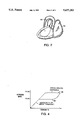
- FIG. 1 is a schematic diagram showing introduction into the body of an acoustic imaging catheter according to the invention, while FIG. 2 illustrates severe bending of the catheter as it accesses the heart.
- FIG. 3 is a longitudinal, partially cut-away view of the distal end of the catheter.
- FIG. 4 is a stress-strain curve for superelastic nitinol.
- FIGS. 5 and 6 are longitudinal views of a partially constructed drive shaft.
- FIGS. 7, 8 and 9 are schematic diagrams of a nitinol coil under construction.
- FIG. 10 is a cut-away view of a drive shaft in one embodiment.
- FIGS. 11 and 12 are side and cross-sectional views of the drive shaft in another embodiment.
- FIG. 13 is a cut-away view of a drive shaft.
- a micro acoustic imaging catheter 10 images the body with a miniature rotatable transducer 12 in its distal end 13 which is positioned in the body, e.g. in a blood vessel 14 or the heart 15.
- the transducer is driven by a hollow drive shaft 16 placed within a catheter sheath 18.
- a coaxial cable inside the drive shaft connects the transducer to a relatively rigid connector 20 joining the catheter to a control system 22.
- the control system moves the catheter and monitors and displays the returned transducer signal.
- the relative position of the ultrasound transducer must be accurately known at all times to avoid image distortion of the return signal at the controller. Since the position information is measured from the proximal end 24 of the drive shaft in the preferred embodiment, it is important to have a one-to-one transmission of motion with complete fidelity, meaning that a rotation of the proximal end of the drive shaft at a constant speed causes the transducer to rotate at a corresponding constant speed.
- drive shaft artifact Blur in the image due to lack of one-to-one fidelity is termed drive shaft artifact.
- the drive shaft 16 in one embodiment comprises an inner coil 40 and outer coil 42 of wound nitinol.
- the outer coil has an outer diameter 0.03 and an inner diameter d i of 0.017" and the inner coil has an inner diameter D i of approximately 0.010" and an outer diameter D O of 0.015".
- Each coil is of multifilar construction, having between 3 to 10 filaments, one of which (44) is shown by shading, each made of a wire with a minimum cross-sectional diameter of about 0.002".
- the outer diameter of the drive shaft as a whole ranges from about 0.012" to about 0.06", with wire diameters ranging from about 0.002" to about 0.007", respectively.
- the coils are closely wound, in counterwound relationship, with an inner pitch angle ⁇ 0 and ⁇ 1 where ⁇ 0 is smaller than ⁇ 1 , e.g., 22.5 and 31 degrees, respectively.
- the pitch angles are chosen to eliminate space 46 between turns of the wires, and to apply a substantial part of the stress from either tension or compression in the direction along the axis of the wire filaments.
- the two coils fit together, as described below, so that they interfere with one another when rotated in a given direction, i.e. the outer coil will tend to contract while the inner coil tends to expand, each thereby resisting the radial change of the other.
- the interference significantly increases torsional stiffness in the rotational direction, resulting in a high fidelity drive shaft.
- each coil in the drive shaft is made of a nitinol alloy, having an ultimate tensile strength of 250,000 to 300,000 psi when drawn.
- the alloy is available from Furukawa Electric Company located in both Japan and California. After winding, the coils are heat treated to render them superelastic.
- the nitinol alloy exhibits superelastic characteristics under stress, i.e. it undergoes reversible deformation, changing from Austenite to stress-induced Martensite, as shown in FIG. 4.
- the alloy has a loading plateau 50 of approximately 100,000 psi, and an unloading plateau 52 of approximately 50,000 psi with a temperature transition (A f ) of around 0 to 5 degrees C.
- the wire is a nitinol alloy selected from a wide range comprising from about 40% to 60% nickel with the majority of the balance being titanium.
- Nitinol alloys having a third element, for example, chromium, vanadium or iron as a third element are generally stiffer and stronger than a pure nickel-titanium alloy.
- the preferred range for the ultimate tensile strength of the nitinol alloy is from 200,000 to 400,000 psi with the material exhibiting 3% to 9% reversible elastic deformation; a particularly useful material has 275,000 psi tensile strength with 7% elastic deformation.
- the lower range of elastic deformation (3-4%) is provided by either cold worked, non-superelastic Martensite or Austenite nitinol alloy, or in some cases titanium alloys.
- Coils that are small in diameter are in some cases made of alloys with higher tensile strengths, up to 400,000 psi. A higher tensile strength is achieved by increasing the percentage of nickel in the alloy.
- the cross section of the nitinol wire in various embodiments is circular, oval or rectangular, with a radial dimension (diameter in the case of a circular cross section) ranging from 0.001" to 0.012".
- a circular cross section provides the greatest coil flexibility and largest coil wall thickness, whereas a rectangular cross-section decreases the wall thickness at the expense of some loss of flexibility.
- a rectangular cross section is appropriate, for instance, when the need for smallness of the drive shaft is the primary constraint and when flexibility is relatively less important for example, when the drive shaft does not have to bend tightly but the catheter's outer diameter must be 0.020" or smaller.
- Such wire may be of strip form of thickness about 0.002". The stiffness of the rectangular wire is minimized by decreasing the width of its cross section, i.e. in the direction of becoming square.
- triangular cross sections to provide high flexibility in selected regions of the drive shaft.
- a triangular wire flexes uniformly and provides space between each coil to flex into the other, instead of rolling over one another.
- the drive shaft is manufactured by first winding the selected number of nitinol wire filaments into a coil about a mandrel and securing its free end in tightly wound condition, preferably by means of adhesive, tape or a clamp.
- the tightly wound coil, while remaining on the mandrel, is then subjected to an annealing temperature of 450 C. for fifteen minutes to render it superelastic.
- heating is progressive, only a small section of wire being heated to 450 C. at any time as it is being continuously wound around a mandrel. The continuous coil coming off the mandrel is then wound on a drum.
- the next step is to wind the inner coil tightly on a mandrel, in a direction opposite to the direction of winding of the outer coil.
- the inner coil is then heat treated identically to the outer coil and removed from the mandrel.
- the inner coil is now tightened by sliding it onto a smaller mandrel, securing it at one end, and then either winding, preferably, or stretching the coil, until the coil's inner diameter conforms to that of the smaller mandrel. This can advantageously reduce the outer diameter of the inner coil by about 0.01".
- the inner coil 40 wound in conventional manner on the mandrel 60 is now small enough to be inserted in the outer coil 42 without interference.
- the inner coil is released so that it springs toward its original diameter, causing it to engage the inner diameter of the outer coil with interfering contact.
- the mandrel is then removed and the two coils are secured at one end together by an adhesive, such as a high-temperature epoxy, or by a clamp, such as a copper or steel wire tightly wound around the clamped end.
- the inner coil is torqued in the opposite direction in which it was wound to expand it, while the outer coil is simultaneously torqued to reduce its diameter, causing the two coils to interfere more tightly. Since the coils are counterwound, the torque is applied in the same direction on each of the coils. This results in the bands of the multifilar elements being uniformly distributed.
- the inner coil 40 is released from a first mandrel and then, for assembly, attached to a "fishing" line 70, shown in FIG. 6.
- the inner diameter of the inner coil is reduced by applying tension to the line while pulling the inner coil through the outer coil 42.
- a nitinol wire 44 is drawn from a supply roll 80 through feed rollers 82, and then passes through winding points 84, a pair of which bend the wire into a coil 86.
- the winding points are made of a very hard substance, such as steel, that is not subject to wear.
- a heating stage 88 heats the coil coming off the winding points, making wire 44 superelastic.
- the coil then slides onto a mandrel 90. After the superelastic coil unwinds off the mandrel, it springs back to its initial shape before being wound on a take-up reel 92.
- a wire 44 winds off a supply roll 80 to feed rollers 82.
- the wire is then pulled onto a rotating die 100 in the form of a screw with a central mandrel.
- a forming heater 88 heats the wire wound onto the mandrel as the die rotates.
- Mandrel 90 holds wound coil 86 as it cools, and a take-up reel 92 takes up the coil as it winds off mandrel 90.
- the rotating die is placed in an inert gas chamber 110, seen in FIG. 9, to help prevent contamination of the nitinol.
- Multiple spools 92 wind the multiple wires 44 with a winding machine that has a variable drive rate according the number of filaments being wound or the band width of the multifilar set of filaments.
- the number of spools used are from 3 to 8.
- the wires are led to a winding head, wrapped around a mandrel, and taped or mechanically secured. As the mandrel rotates, the wire is deformed under a wear resistant carbide shoe and wrapped around the mandrel. The carbide shoe maintains tension on the non-superelastic wire to produce tightness of the coils. When the coil on the mandrel is heated, the heat treating relaxes tension in the wire and the resulting superelastic coil is stress-neutral.
- a drive shaft made from the superelastic coils is more resistant to mishandling damage, such as being twisted or bent during manufacture as well as when the catheter may be caught between medical devices in a lab or during insertion.
- Kinks are much less likely to form in the drive shaft, so that the resulting image will be free of drive shaft artifact.
- a very small (0.0055" to 0.009" outer diameter) electrical coaxial cable 120 is placed through its center.
- a transducer housing containing a transducer is attached to one end of the drive shaft with an epoxy.
- the transducer is connected to the coaxial cable 120, and the drive shaft is connected to an electrical connector.
- Such catheters are made in 6.0 French, 4.8 French, 3.5 French, and 3 French sizes.
- the preferred outer dimension of the catheter is 0.018" with a 0.013-0.014" outer diameter drive shaft if the catheter has a sheath. This is accomplished with 0.002" diameter round cross section wire, a 0.0055" outer diameter coaxial cable, and a 0.006" diameter mandrel.
- the drive shaft has a coil combined with a constraining element that opposes any change in size of the coil as it rotates. If the constraint is placed inside the coil, the coil is driven in the direction tending to reduce its diameter while the constraint resists contraction of the coil. If the constraint is outside the coil, the coil is driven in the direction tending to unwind the coil while the exterior constraint resists expansion of the coil.
- a constraining element that opposes any change in size of the coil as it rotates.
- the drive shaft has an inner coil 115 of stainless steel and an outer coil 122 of nitinol.
- the steel coil has an inner diameter d i of 0.008" and an outer diameter d o of 0.012"; the nitinol has an outer diameter D o of 0.016".
- the outer superelastic coil which, due to geometrical considerations, is stressed more during bending than is the inner coil, is better able to resist yielding or kinking than a steel coil.
- the springback properties of the steel coil are used to easily achieve good distribution of the coils and an initial level of interference between the inner and outer coil, eliminating the need to wind the inner coil on a reduced size mandrel before insertion into the outer coil.
- a structure with an inner superelastic coil and an outer stainless steel coil can provide good torsional performance while also providing adequate resistance to kinking under certain circumstances.
- the drive shaft in another embodiment is composed of a single multifilar nitinol coil 130 and an outside sleeve 132 of a very thin (0.002") polyester material that constrains the coil.
- the polyester sleeve has the lateral support of the nitinol all along its length so that under axial columnar load it does not kink, i.e., it is not subject to columnar collapse.
- the imaging catheter using this type of drive shaft therefore can have an extremely small outer diameter and be capable of accessing very restricted regions of the body.
- the nitinol coil and the polyester tube are constructed by winding the inner nitinol coil on a reduced size mandrel as mentioned above, fixing a tube around the coil and mandrel, and releasing tension on the coil so that it springs out against the tube.
- the drive shaft is made by placing the inner coil on a mandrel, and then heat shrinking over that inner coil a heat shrinkable polyester tube.
- the nitinol coil 130 is embedded between two polyester coatings 132, 134.
- the layered construction has an inner coil that is a braided wire instead of a spring winding, that is wound over an existing length of extruded tubing. Polymer tubings are subsequently shrunk over the braided winding.
- the final wall thickness of the drive shaft is 3 to 4 layers thick.
- the coil is run through an extruder that extrudes the polyester layer on the outside of the coil.
- the outer diameter of the coil and the gap between each winding of the coil is tightly controlled by winding the coil on a mandrel, allowing a very uniform coating of polymer to be placed on the coil to form a flexible drive shaft.
- a drive shaft can have applications in imaging catheters with an outer diameter of 0.018 inches or smaller.
- Nitinol coils manufactured in the ways just described can thus be joined to or embedded in the walls of thin tubes, or coated to form such tubes, to enhance the compression resistance of thin walled tubular members over a wide range of tube diameters for use in catheters.
- the provision of such kink resistant catheter walls is another important feature of the present invention.
- a single nitinol coil 140 is bonded periodically to a coaxial cable 120 in its center to maintain stress on the coil.
- the coaxial cable is an electrical transmission line with 0.0055" to 0.010" outer diameter.
- the coaxial cable may also have an outer sheath that is plastic. If it is unsheathed, the coaxial cable has an inner conductor with an insulator that is very carefully controlled in thickness and an outer conductor (copper) which conforms to the insulator.
- an adhesive is applied to bind the coil to the coaxial cable along its entire length with half an inch to two inches spacing between successive bonds 142.
- the adhesive is a flexible epoxy in order to have a flexible drive shaft, and is low viscosity, so that it can penetrate easily between the windings of the coil.
- the coil is radially compressed during the bonding to reduce the space between the coaxial cable and the coil and to maintain the coil in a state of tension. Bonding the coil to the coaxial cable thus can limit the amount of wind up that may occur over the length of the coil, and thus can serve to reduce drive shaft artifact.
- a single layer coil bonded to a coaxial cable or to polyester tubing is a preferred embodiment in certain instances when the wall thickness of the drive shaft needs to be limited to achieve a small outer diameter.
- the single layer coil construction reduces the outer diameter of the drive shaft by two wire diameters over an interfering dual coil construction. This enables the drive shaft to enter deeply into the body and into highly restricted regions, such as the coronary arteries and the neurovascular system. Larger coils, such as the dual coil drive shaft described above, are advantageous in imaging the gastrointestinal, urinary and esophageal tracts, the gall bladder, the peripheral arteries and other body ducts.
Landscapes
- Health & Medical Sciences (AREA)
- Life Sciences & Earth Sciences (AREA)
- Engineering & Computer Science (AREA)
- Physics & Mathematics (AREA)
- Veterinary Medicine (AREA)
- Biophysics (AREA)
- Biomedical Technology (AREA)
- Heart & Thoracic Surgery (AREA)
- Public Health (AREA)
- Animal Behavior & Ethology (AREA)
- General Health & Medical Sciences (AREA)
- Medical Informatics (AREA)
- Nuclear Medicine, Radiotherapy & Molecular Imaging (AREA)
- Pathology (AREA)
- Radiology & Medical Imaging (AREA)
- Molecular Biology (AREA)
- Surgery (AREA)
- Acoustics & Sound (AREA)
- Multimedia (AREA)
- Pulmonology (AREA)
- Anesthesiology (AREA)
- Hematology (AREA)
- Media Introduction/Drainage Providing Device (AREA)
- Ultra Sonic Daignosis Equipment (AREA)
Abstract
Description
Claims (30)
Priority Applications (7)
| Application Number | Priority Date | Filing Date | Title |
|---|---|---|---|
| US08/144,275 US5437282A (en) | 1993-10-29 | 1993-10-29 | Drive shaft for acoustic imaging catheters and flexible catheters |
| CA002174852A CA2174852A1 (en) | 1993-10-29 | 1994-10-27 | Drive shaft for acoustic imaging catheters |
| PCT/US1994/012354 WO1995011628A1 (en) | 1993-10-29 | 1994-10-27 | Drive shaft for acoustic imaging catheters |
| DE69433689T DE69433689T2 (en) | 1993-10-29 | 1994-10-27 | DRIVE SHAFT FOR A CATHETER FOR IMAGING BY MEANS OF ACOUSTIC ELEMENTS |
| JP51283295A JP3626495B2 (en) | 1993-10-29 | 1994-10-27 | Drive shaft for an acoustic imaging catheter |
| EP94932080A EP0725596B1 (en) | 1993-10-29 | 1994-10-27 | Drive shaft for acoustic imaging catheters |
| US08/781,503 US5932035A (en) | 1993-10-29 | 1997-01-08 | Drive shaft for acoustic imaging catheters and flexible catheters |
Applications Claiming Priority (1)
| Application Number | Priority Date | Filing Date | Title |
|---|---|---|---|
| US08/144,275 US5437282A (en) | 1993-10-29 | 1993-10-29 | Drive shaft for acoustic imaging catheters and flexible catheters |
Related Child Applications (1)
| Application Number | Title | Priority Date | Filing Date |
|---|---|---|---|
| US50987095A Division | 1993-10-29 | 1995-08-01 |
Publications (1)
| Publication Number | Publication Date |
|---|---|
| US5437282A true US5437282A (en) | 1995-08-01 |
Family
ID=22507861
Family Applications (2)
| Application Number | Title | Priority Date | Filing Date |
|---|---|---|---|
| US08/144,275 Expired - Lifetime US5437282A (en) | 1993-10-29 | 1993-10-29 | Drive shaft for acoustic imaging catheters and flexible catheters |
| US08/781,503 Expired - Fee Related US5932035A (en) | 1993-10-29 | 1997-01-08 | Drive shaft for acoustic imaging catheters and flexible catheters |
Family Applications After (1)
| Application Number | Title | Priority Date | Filing Date |
|---|---|---|---|
| US08/781,503 Expired - Fee Related US5932035A (en) | 1993-10-29 | 1997-01-08 | Drive shaft for acoustic imaging catheters and flexible catheters |
Country Status (6)
| Country | Link |
|---|---|
| US (2) | US5437282A (en) |
| EP (1) | EP0725596B1 (en) |
| JP (1) | JP3626495B2 (en) |
| CA (1) | CA2174852A1 (en) |
| DE (1) | DE69433689T2 (en) |
| WO (1) | WO1995011628A1 (en) |
Cited By (42)
| Publication number | Priority date | Publication date | Assignee | Title |
|---|---|---|---|---|
| US5546947A (en) * | 1993-09-30 | 1996-08-20 | Terumo Kabushiki Kaisha | Ultrasonic endoprobe |
| EP0806596A1 (en) * | 1996-04-30 | 1997-11-12 | Target Therapeutics, Inc. | Super-elastic alloy braid structure |
| EP0806219A1 (en) * | 1996-04-30 | 1997-11-12 | Target Therapeutics, Inc. | Composite braided guidewire |
| US5738100A (en) * | 1995-06-30 | 1998-04-14 | Terumo Kabushiki Kaisha | Ultrasonic imaging catheter |
| WO1999039639A1 (en) * | 1998-02-03 | 1999-08-12 | Boston Scientific Limited | Integrated coaxial transmission line and flexible drive cable |
| US6017312A (en) * | 1998-02-03 | 2000-01-25 | Boston Scientific Corporation | Multi-channel rotary transformer |
| WO1999049910A3 (en) * | 1998-03-31 | 2000-02-17 | Transvascular Inc | Transvascular catheters having imaging transducers |
| US6120454A (en) * | 1998-02-03 | 2000-09-19 | Boston Scientific Corporation | Annular array ultrasound catheter |
| US6159165A (en) | 1997-12-05 | 2000-12-12 | Micrus Corporation | Three dimensional spherical micro-coils manufactured from radiopaque nickel-titanium microstrand |
| US6231515B1 (en) * | 1999-01-13 | 2001-05-15 | Scimed Life Systems, Inc. | Safety mechanism and method to prevent rotating imaging guide device from exiting a catheter |
| US6358211B1 (en) | 1999-10-12 | 2002-03-19 | Scimed Life Systems, Inc. | Ultrasound lucent apparatus and methods of using |
| US6375615B1 (en) | 1995-10-13 | 2002-04-23 | Transvascular, Inc. | Tissue penetrating catheters having integral imaging transducers and their methods of use |
| WO2002032314A1 (en) * | 2000-10-18 | 2002-04-25 | B-K Medical A/S | Ultrasonic apparatus with rotatable probe, surrounded by a protective resilent sleeve |
| US6383204B1 (en) | 1998-12-15 | 2002-05-07 | Micrus Corporation | Variable stiffness coil for vasoocclusive devices |
| WO2002026410A3 (en) * | 2000-09-29 | 2002-07-04 | Nat Inst Health | Method to fabricate continuous lengths of helical coil shaped memory wire |
| US20030097072A1 (en) * | 2001-01-04 | 2003-05-22 | Manuel Serrano | Method of mounting a transducer to a driveshaft |
| US20040193239A1 (en) * | 2001-04-27 | 2004-09-30 | Falwell Gary S | Electrophysiology catheter for mapping and/or ablation |
| US20040193057A1 (en) * | 2003-03-28 | 2004-09-30 | Scimed Life Systems, Inc. | Imaging transducer assembly |
| EP1454588A3 (en) * | 2003-03-03 | 2004-10-13 | Olympus Corporation | Force transmission coil for flexible endoscopic instrument and medical treatment tool using said coil |
| US20050106806A1 (en) * | 2003-11-13 | 2005-05-19 | Fred Fishburn | Methods of forming a double-sided capacitor or a contact using a sacrificial structure |
| US20060241366A1 (en) * | 2002-10-31 | 2006-10-26 | Gary Falwell | Electrophysiology loop catheter |
| US20060253028A1 (en) * | 2005-04-20 | 2006-11-09 | Scimed Life Systems, Inc. | Multiple transducer configurations for medical ultrasound imaging |
| US20070016054A1 (en) * | 2005-07-01 | 2007-01-18 | Scimed Life Systems, Inc. | Medical imaging device having a forward looking flow detector |
| US20070021749A1 (en) * | 2005-06-21 | 2007-01-25 | Keita Suzuki | High-frequency treatment instrument |
| EP1929955A1 (en) * | 1998-10-23 | 2008-06-11 | Boston Scientific Limited | Improved system for intraluminal imaging |
| US20080194910A1 (en) * | 2007-02-08 | 2008-08-14 | Olympus Medical Systems Corp. | Treatment tool for endoscope |
| US20080195143A1 (en) * | 2007-02-08 | 2008-08-14 | Olympus Medical Systems Corp. | Endoscope treatment tool |
| US7544166B2 (en) | 2005-06-03 | 2009-06-09 | Scimed Life Systems, Inc. | Systems and methods for imaging with deployable imaging devices |
| US20100276407A1 (en) * | 2008-10-28 | 2010-11-04 | Cooper Edward L | Conduit |
| US20130158896A1 (en) * | 2010-07-12 | 2013-06-20 | Custom Fluid Power Pty Ltd. | Pressure detection device |
| WO2014100532A1 (en) * | 2012-12-21 | 2014-06-26 | Joseph Fallon | Rotational imaging apparatus |
| US20140277005A1 (en) * | 2013-03-14 | 2014-09-18 | Covidien Lp | Medical device including flexible elongate torque-transmitting member |
| US8870908B2 (en) | 2007-08-17 | 2014-10-28 | DePuy Synthes Products, LLC | Twisted primary coil for vascular therapy |
| US9427550B2 (en) | 2012-11-09 | 2016-08-30 | St. Jude Medical, Cardiology Division, Inc. | Devices and methods for delivering vascular implants |
| EP3169376A4 (en) * | 2014-07-14 | 2018-07-04 | Smarter Alloys Inc. | Multiple memory materials and systems, methods and applications therefor |
| US20180206872A1 (en) * | 2014-09-30 | 2018-07-26 | Imott Inc. | Scissors |
| US10052122B2 (en) | 2014-01-17 | 2018-08-21 | Cardiovascular Systems, Inc. | Spin-to-open atherectomy device with electric motor control |
| US10238466B2 (en) * | 2017-06-15 | 2019-03-26 | Cook Medical Technologies Llc | Method of making a superelastic medical device with a radiopaque marker |
| US10335042B2 (en) | 2013-06-28 | 2019-07-02 | Cardiovascular Systems, Inc. | Methods, devices and systems for sensing, measuring and/or characterizing vessel and/or lesion compliance and/or elastance changes during vascular procedures |
| US20210077145A1 (en) * | 2017-05-08 | 2021-03-18 | Danmarks Tekniske Universitet | A needle and a method of making a needle |
| WO2021142273A1 (en) * | 2020-01-10 | 2021-07-15 | Elco Enterprises, Inc. | Weld wire guide conduit |
| US20220062624A1 (en) * | 2020-08-31 | 2022-03-03 | Advanced Neuromodulation Systems, Inc. | Implantable stimulation lead including a coiled lead body and methods for forming the same |
Families Citing this family (87)
| Publication number | Priority date | Publication date | Assignee | Title |
|---|---|---|---|---|
| US6183487B1 (en) * | 1997-03-06 | 2001-02-06 | Scimed Life Systems, Inc. | Ablation device for reducing damage to vessels and/or in-vivo stents |
| US6203534B1 (en) * | 1999-08-10 | 2001-03-20 | Biosense Webster, Inc. | Catheter with protective covering |
| JP4898993B2 (en) * | 2000-01-28 | 2012-03-21 | クック メディカル テクノロジーズ エルエルシー | Intravascular medical device with multiple wires |
| US6475224B1 (en) | 2000-04-13 | 2002-11-05 | Scimed Life Systems, Inc. | Catheter drive shaft spring clutch |
| US6517528B1 (en) | 2000-04-13 | 2003-02-11 | Scimed Life Systems, Inc. | Magnetic catheter drive shaft clutch |
| US6454717B1 (en) | 2000-04-13 | 2002-09-24 | Scimed Life Systems, Inc. | Concentric catheter drive shaft clutch |
| US6413222B1 (en) | 2000-04-13 | 2002-07-02 | Boston Scientific Corporation | Catheter drive shaft clutch |
| DE10105592A1 (en) | 2001-02-06 | 2002-08-08 | Achim Goepferich | Placeholder for drug release in the frontal sinus |
| US20030093060A1 (en) * | 2001-11-09 | 2003-05-15 | Vadnais Technologies Corporation | Catheter assembly |
| US8317816B2 (en) | 2002-09-30 | 2012-11-27 | Acclarent, Inc. | Balloon catheters and methods for treating paranasal sinuses |
| JP4098613B2 (en) * | 2002-12-11 | 2008-06-11 | 朝日インテック株式会社 | Hollow stranded wire coil body, medical instrument using the same, and manufacturing method thereof |
| EP1659950A1 (en) * | 2003-08-20 | 2006-05-31 | Hansen Medical, Inc. | System and method for 3-d imaging |
| WO2005102213A1 (en) | 2004-04-16 | 2005-11-03 | Cook, Inc. | Removable vena cava filter having primary struts for enhanced retrieval and delivery |
| US7625390B2 (en) * | 2004-04-16 | 2009-12-01 | Cook Incorporated | Removable vena cava filter |
| WO2005102212A1 (en) | 2004-04-16 | 2005-11-03 | Cook, Inc. | Removable vena cava filter with anchoring feature for reduced trauma |
| DE602005027189D1 (en) | 2004-04-16 | 2011-05-12 | Cook William Europ | REMOVABLE VENA CAVA FILTER FOR REDUCING TRAUMATA IN THE FOLDED CONDITION |
| JP4918637B2 (en) | 2004-04-16 | 2012-04-18 | クック メディカル テクノロジーズ エルエルシー | Retrievable vena cava filter with anchor hooks positioned inward in a folded configuration |
| US7654997B2 (en) | 2004-04-21 | 2010-02-02 | Acclarent, Inc. | Devices, systems and methods for diagnosing and treating sinusitus and other disorders of the ears, nose and/or throat |
| US9554691B2 (en) | 2004-04-21 | 2017-01-31 | Acclarent, Inc. | Endoscopic methods and devices for transnasal procedures |
| US8747389B2 (en) | 2004-04-21 | 2014-06-10 | Acclarent, Inc. | Systems for treating disorders of the ear, nose and throat |
| US7361168B2 (en) | 2004-04-21 | 2008-04-22 | Acclarent, Inc. | Implantable device and methods for delivering drugs and other substances to treat sinusitis and other disorders |
| US20060004323A1 (en) | 2004-04-21 | 2006-01-05 | Exploramed Nc1, Inc. | Apparatus and methods for dilating and modifying ostia of paranasal sinuses and other intranasal or paranasal structures |
| US9101384B2 (en) | 2004-04-21 | 2015-08-11 | Acclarent, Inc. | Devices, systems and methods for diagnosing and treating sinusitis and other disorders of the ears, Nose and/or throat |
| US9089258B2 (en) | 2004-04-21 | 2015-07-28 | Acclarent, Inc. | Endoscopic methods and devices for transnasal procedures |
| US20070167682A1 (en) | 2004-04-21 | 2007-07-19 | Acclarent, Inc. | Endoscopic methods and devices for transnasal procedures |
| US7410480B2 (en) | 2004-04-21 | 2008-08-12 | Acclarent, Inc. | Devices and methods for delivering therapeutic substances for the treatment of sinusitis and other disorders |
| US10188413B1 (en) | 2004-04-21 | 2019-01-29 | Acclarent, Inc. | Deflectable guide catheters and related methods |
| US7559925B2 (en) | 2006-09-15 | 2009-07-14 | Acclarent Inc. | Methods and devices for facilitating visualization in a surgical environment |
| US8864787B2 (en) | 2004-04-21 | 2014-10-21 | Acclarent, Inc. | Ethmoidotomy system and implantable spacer devices having therapeutic substance delivery capability for treatment of paranasal sinusitis |
| US7462175B2 (en) | 2004-04-21 | 2008-12-09 | Acclarent, Inc. | Devices, systems and methods for treating disorders of the ear, nose and throat |
| US8702626B1 (en) | 2004-04-21 | 2014-04-22 | Acclarent, Inc. | Guidewires for performing image guided procedures |
| US8146400B2 (en) * | 2004-04-21 | 2012-04-03 | Acclarent, Inc. | Endoscopic methods and devices for transnasal procedures |
| US20060063973A1 (en) | 2004-04-21 | 2006-03-23 | Acclarent, Inc. | Methods and apparatus for treating disorders of the ear, nose and throat |
| US8894614B2 (en) | 2004-04-21 | 2014-11-25 | Acclarent, Inc. | Devices, systems and methods useable for treating frontal sinusitis |
| US9351750B2 (en) | 2004-04-21 | 2016-05-31 | Acclarent, Inc. | Devices and methods for treating maxillary sinus disease |
| US8932276B1 (en) | 2004-04-21 | 2015-01-13 | Acclarent, Inc. | Shapeable guide catheters and related methods |
| US20190314620A1 (en) | 2004-04-21 | 2019-10-17 | Acclarent, Inc. | Apparatus and methods for dilating and modifying ostia of paranasal sinuses and other intranasal or paranasal structures |
| US20070208252A1 (en) | 2004-04-21 | 2007-09-06 | Acclarent, Inc. | Systems and methods for performing image guided procedures within the ear, nose, throat and paranasal sinuses |
| US9399121B2 (en) | 2004-04-21 | 2016-07-26 | Acclarent, Inc. | Systems and methods for transnasal dilation of passageways in the ear, nose or throat |
| US7803150B2 (en) | 2004-04-21 | 2010-09-28 | Acclarent, Inc. | Devices, systems and methods useable for treating sinusitis |
| US7419497B2 (en) | 2004-04-21 | 2008-09-02 | Acclarent, Inc. | Methods for treating ethmoid disease |
| US8764729B2 (en) | 2004-04-21 | 2014-07-01 | Acclarent, Inc. | Frontal sinus spacer |
| US7416534B2 (en) * | 2004-06-22 | 2008-08-26 | Boston Scientific Scimed, Inc. | Medical device including actuator |
| CN101031254B (en) | 2004-09-27 | 2010-10-27 | 库克公司 | Removable vena cava filter including struts with axial bends |
| WO2006052894A1 (en) * | 2004-11-08 | 2006-05-18 | Cook, Inc. | Blood clot filter configured for a wire guide |
| US7666143B2 (en) * | 2004-12-14 | 2010-02-23 | Siemens Medical Solutions Usa, Inc. | Array rotation for ultrasound catheters |
| EP3175827B1 (en) * | 2004-12-15 | 2019-03-06 | Cook Medical Technologies LLC | Multifilar cable catheter |
| US8951225B2 (en) | 2005-06-10 | 2015-02-10 | Acclarent, Inc. | Catheters with non-removable guide members useable for treatment of sinusitis |
| US8114113B2 (en) | 2005-09-23 | 2012-02-14 | Acclarent, Inc. | Multi-conduit balloon catheter |
| US8190389B2 (en) | 2006-05-17 | 2012-05-29 | Acclarent, Inc. | Adapter for attaching electromagnetic image guidance components to a medical device |
| US9820688B2 (en) | 2006-09-15 | 2017-11-21 | Acclarent, Inc. | Sinus illumination lightwire device |
| US8439687B1 (en) | 2006-12-29 | 2013-05-14 | Acclarent, Inc. | Apparatus and method for simulated insertion and positioning of guidewares and other interventional devices |
| US8118757B2 (en) | 2007-04-30 | 2012-02-21 | Acclarent, Inc. | Methods and devices for ostium measurement |
| US8162959B2 (en) | 2007-05-03 | 2012-04-24 | Boston Scientific Scimed, Inc. | Single stage hemostasis clipping device |
| US8485199B2 (en) | 2007-05-08 | 2013-07-16 | Acclarent, Inc. | Methods and devices for protecting nasal turbinate during surgery |
| US8657845B2 (en) * | 2007-05-15 | 2014-02-25 | Cook Medical Technologies Llc | Multifilar cable catheter |
| US20080306322A1 (en) * | 2007-06-07 | 2008-12-11 | Jervis James E | Everting gynecological brachytherapy applicator |
| WO2009009799A1 (en) * | 2007-07-12 | 2009-01-15 | Volcano Corporation | Catheter for in vivo imaging |
| US10206821B2 (en) | 2007-12-20 | 2019-02-19 | Acclarent, Inc. | Eustachian tube dilation balloon with ventilation path |
| US8246672B2 (en) | 2007-12-27 | 2012-08-21 | Cook Medical Technologies Llc | Endovascular graft with separately positionable and removable frame units |
| US8182432B2 (en) | 2008-03-10 | 2012-05-22 | Acclarent, Inc. | Corewire design and construction for medical devices |
| CN102112040B (en) | 2008-07-30 | 2015-04-01 | 阿克拉伦特公司 | Paranasal ostium finder devices and methods |
| RU2506056C2 (en) | 2008-09-18 | 2014-02-10 | Аккларент, Инк. | Methods and apparatus for treating ear, nose and throat diseases |
| US8117817B2 (en) * | 2008-10-09 | 2012-02-21 | W. C. Heraeus Gmbh | Helically-wound cable and method |
| US8250844B2 (en) * | 2008-10-09 | 2012-08-28 | W. C. Heraeus Gmbh | Helically-wound cable and method |
| US8246648B2 (en) | 2008-11-10 | 2012-08-21 | Cook Medical Technologies Llc | Removable vena cava filter with improved leg |
| US20100241155A1 (en) | 2009-03-20 | 2010-09-23 | Acclarent, Inc. | Guide system with suction |
| US8435290B2 (en) | 2009-03-31 | 2013-05-07 | Acclarent, Inc. | System and method for treatment of non-ventilating middle ear by providing a gas pathway through the nasopharynx |
| US7978742B1 (en) | 2010-03-24 | 2011-07-12 | Corning Incorporated | Methods for operating diode lasers |
| EP2756792A1 (en) | 2010-09-08 | 2014-07-23 | Covidien LP | Catheter with imaging assembly |
| US9155492B2 (en) | 2010-09-24 | 2015-10-13 | Acclarent, Inc. | Sinus illumination lightwire device |
| US10022212B2 (en) | 2011-01-13 | 2018-07-17 | Cook Medical Technologies Llc | Temporary venous filter with anti-coagulant delivery method |
| USD717340S1 (en) | 2012-09-07 | 2014-11-11 | Covidien Lp | Display screen with enteral feeding icon |
| US9198835B2 (en) | 2012-09-07 | 2015-12-01 | Covidien Lp | Catheter with imaging assembly with placement aid and related methods therefor |
| USD735343S1 (en) | 2012-09-07 | 2015-07-28 | Covidien Lp | Console |
| USD716841S1 (en) | 2012-09-07 | 2014-11-04 | Covidien Lp | Display screen with annotate file icon |
| US9517184B2 (en) | 2012-09-07 | 2016-12-13 | Covidien Lp | Feeding tube with insufflation device and related methods therefor |
| US20140163360A1 (en) * | 2012-12-07 | 2014-06-12 | Boston Scientific Scimed, Inc. | Irrigated catheter |
| US9867620B2 (en) * | 2013-03-14 | 2018-01-16 | Covidien Lp | Articulation joint for apparatus for endoscopic procedures |
| JP6117422B2 (en) | 2013-03-15 | 2017-04-19 | ボストン サイエンティフィック サイムド,インコーポレイテッドBoston Scientific Scimed,Inc. | Open irrigation ablation catheter |
| CN105188588B (en) | 2013-03-15 | 2017-10-10 | 波士顿科学医学有限公司 | The opening open irrigated ablation catheters cooled down with near-end |
| US9629684B2 (en) | 2013-03-15 | 2017-04-25 | Acclarent, Inc. | Apparatus and method for treatment of ethmoid sinusitis |
| US9433437B2 (en) | 2013-03-15 | 2016-09-06 | Acclarent, Inc. | Apparatus and method for treatment of ethmoid sinusitis |
| EP4505946A3 (en) | 2015-10-09 | 2025-02-26 | Boston Scientific Scimed Inc. | Intravascular ultrasound systems and catheters with a manual pullback arrangement |
| US11511085B2 (en) | 2015-11-18 | 2022-11-29 | Heraeus Deutschland GmbH & Co. KG | Torque coil and method |
| EP3554405A1 (en) | 2016-12-19 | 2019-10-23 | Boston Scientific Scimed Inc. | Open-irrigated ablation catheter with proximal insert cooling |
| JP7796515B2 (en) * | 2021-11-25 | 2026-01-09 | 朝日インテック株式会社 | Two-layer coil structure |
Citations (12)
| Publication number | Priority date | Publication date | Assignee | Title |
|---|---|---|---|---|
| US4817613A (en) * | 1987-07-13 | 1989-04-04 | Devices For Vascular Intervention, Inc. | Guiding catheter |
| JPH01170474A (en) * | 1987-12-25 | 1989-07-05 | Terumo Corp | Guide wire for catheter |
| JPH01170475A (en) * | 1987-12-25 | 1989-07-05 | Terumo Corp | Guide wire for catheter |
| US4849032A (en) * | 1987-03-18 | 1989-07-18 | Tomy, Inc. | Orthodontic coil spring and method of making the same |
| US4951677A (en) * | 1988-03-21 | 1990-08-28 | Prutech Research And Development Partnership Ii | Acoustic imaging catheter and the like |
| JPH03168155A (en) * | 1989-11-29 | 1991-07-19 | Furukawa Electric Co Ltd:The | Tube for catheter |
| US5046948A (en) * | 1989-05-29 | 1991-09-10 | Gac International, Inc. | Orthodontic coil spring |
| JPH04236967A (en) * | 1991-01-21 | 1992-08-25 | Tokin Corp | Catheter guide wire |
| US5221269A (en) * | 1990-10-15 | 1993-06-22 | Cook Incorporated | Guide for localizing a nonpalpable breast lesion |
| US5228441A (en) * | 1991-02-15 | 1993-07-20 | Lundquist Ingemar H | Torquable catheter and method |
| US5348017A (en) * | 1993-01-19 | 1994-09-20 | Cardiovascular Imaging Systems, Inc. | Drive shaft for an intravascular catheter system |
| US5368049A (en) * | 1991-05-21 | 1994-11-29 | C. R. Bard, Inc. | Superelastic formable guidewire with malleable cladding |
Family Cites Families (14)
| Publication number | Priority date | Publication date | Assignee | Title |
|---|---|---|---|---|
| US1228439A (en) * | 1914-01-30 | 1917-06-05 | Clarence F Hotchkiss | Flexible shaft. |
| US4283233A (en) * | 1980-03-07 | 1981-08-11 | The United States Of America As Represented By The Secretary Of The Navy | Method of modifying the transition temperature range of TiNi base shape memory alloys |
| JPS6217790Y2 (en) * | 1981-04-15 | 1987-05-08 | ||
| JPS61165244A (en) * | 1985-01-14 | 1986-07-25 | Sumitomo Electric Ind Ltd | Production of niti shape memory alloy coil spring |
| JPH0617521B2 (en) * | 1985-04-02 | 1994-03-09 | 而至歯科工業株式会社 | Dental Au-Cu-Zu alloy using super elasticity |
| US5154705A (en) * | 1987-09-30 | 1992-10-13 | Lake Region Manufacturing Co., Inc. | Hollow lumen cable apparatus |
| JPH01242763A (en) * | 1988-03-23 | 1989-09-27 | Hitachi Metals Ltd | Manufacture of ti-ni shape memory alloy reduced in hysteresis |
| US5203772A (en) * | 1989-01-09 | 1993-04-20 | Pilot Cardiovascular Systems, Inc. | Steerable medical device |
| US5120308A (en) * | 1989-05-03 | 1992-06-09 | Progressive Angioplasty Systems, Inc. | Catheter with high tactile guide wire |
| US4990155A (en) * | 1989-05-19 | 1991-02-05 | Wilkoff Howard M | Surgical stent method and apparatus |
| US5061914A (en) * | 1989-06-27 | 1991-10-29 | Tini Alloy Company | Shape-memory alloy micro-actuator |
| JP2851086B2 (en) * | 1989-11-24 | 1999-01-27 | 古河電気工業株式会社 | Manufacturing method of two-way shape memory coil spring |
| US5108411A (en) * | 1990-03-28 | 1992-04-28 | Cardiovascular Imaging Systems, Inc. | Flexible catheter drive cable |
| EP0520073B1 (en) * | 1991-01-16 | 1996-08-14 | The Furukawa Electric Co., Ltd. | Method of continuous processing of wire rod |
-
1993
- 1993-10-29 US US08/144,275 patent/US5437282A/en not_active Expired - Lifetime
-
1994
- 1994-10-27 CA CA002174852A patent/CA2174852A1/en not_active Abandoned
- 1994-10-27 JP JP51283295A patent/JP3626495B2/en not_active Expired - Lifetime
- 1994-10-27 DE DE69433689T patent/DE69433689T2/en not_active Expired - Fee Related
- 1994-10-27 EP EP94932080A patent/EP0725596B1/en not_active Expired - Lifetime
- 1994-10-27 WO PCT/US1994/012354 patent/WO1995011628A1/en not_active Ceased
-
1997
- 1997-01-08 US US08/781,503 patent/US5932035A/en not_active Expired - Fee Related
Patent Citations (13)
| Publication number | Priority date | Publication date | Assignee | Title |
|---|---|---|---|---|
| US4849032A (en) * | 1987-03-18 | 1989-07-18 | Tomy, Inc. | Orthodontic coil spring and method of making the same |
| US4849032B1 (en) * | 1987-03-18 | 1992-06-16 | Gac Int Inc | |
| US4817613A (en) * | 1987-07-13 | 1989-04-04 | Devices For Vascular Intervention, Inc. | Guiding catheter |
| JPH01170474A (en) * | 1987-12-25 | 1989-07-05 | Terumo Corp | Guide wire for catheter |
| JPH01170475A (en) * | 1987-12-25 | 1989-07-05 | Terumo Corp | Guide wire for catheter |
| US4951677A (en) * | 1988-03-21 | 1990-08-28 | Prutech Research And Development Partnership Ii | Acoustic imaging catheter and the like |
| US5046948A (en) * | 1989-05-29 | 1991-09-10 | Gac International, Inc. | Orthodontic coil spring |
| JPH03168155A (en) * | 1989-11-29 | 1991-07-19 | Furukawa Electric Co Ltd:The | Tube for catheter |
| US5221269A (en) * | 1990-10-15 | 1993-06-22 | Cook Incorporated | Guide for localizing a nonpalpable breast lesion |
| JPH04236967A (en) * | 1991-01-21 | 1992-08-25 | Tokin Corp | Catheter guide wire |
| US5228441A (en) * | 1991-02-15 | 1993-07-20 | Lundquist Ingemar H | Torquable catheter and method |
| US5368049A (en) * | 1991-05-21 | 1994-11-29 | C. R. Bard, Inc. | Superelastic formable guidewire with malleable cladding |
| US5348017A (en) * | 1993-01-19 | 1994-09-20 | Cardiovascular Imaging Systems, Inc. | Drive shaft for an intravascular catheter system |
Cited By (78)
| Publication number | Priority date | Publication date | Assignee | Title |
|---|---|---|---|---|
| US7883474B1 (en) | 1993-05-11 | 2011-02-08 | Target Therapeutics, Inc. | Composite braided guidewire |
| US5546947A (en) * | 1993-09-30 | 1996-08-20 | Terumo Kabushiki Kaisha | Ultrasonic endoprobe |
| US5738100A (en) * | 1995-06-30 | 1998-04-14 | Terumo Kabushiki Kaisha | Ultrasonic imaging catheter |
| US20100121357A1 (en) * | 1995-10-13 | 2010-05-13 | Medtronic Vascular, Inc. | Tissue Penetrating Catheters having Integral Imaging Transducers and Their Methods of Use |
| US6375615B1 (en) | 1995-10-13 | 2002-04-23 | Transvascular, Inc. | Tissue penetrating catheters having integral imaging transducers and their methods of use |
| US7637870B2 (en) | 1995-10-13 | 2009-12-29 | Medtronic Vascular, Inc. | Tissue penetrating catheters having integral imaging transducers and their methods of use |
| US8727988B2 (en) | 1995-10-13 | 2014-05-20 | Medtronic Vascular, Inc. | Tissue penetrating catheters having integral imaging transducers and their methods of use |
| US5927345A (en) * | 1996-04-30 | 1999-07-27 | Target Therapeutics, Inc. | Super-elastic alloy braid structure |
| EP0806219A1 (en) * | 1996-04-30 | 1997-11-12 | Target Therapeutics, Inc. | Composite braided guidewire |
| EP0806596A1 (en) * | 1996-04-30 | 1997-11-12 | Target Therapeutics, Inc. | Super-elastic alloy braid structure |
| US6159165A (en) | 1997-12-05 | 2000-12-12 | Micrus Corporation | Three dimensional spherical micro-coils manufactured from radiopaque nickel-titanium microstrand |
| US7326225B2 (en) | 1997-12-05 | 2008-02-05 | Micrus Endovascular Corporation | Vasoocclusive device for treatment of aneurysms |
| US6616617B1 (en) | 1997-12-05 | 2003-09-09 | Micrus Corporation | Vasoocclusive device for treatment of aneurysms |
| US6344037B1 (en) | 1998-02-03 | 2002-02-05 | Scimed Life Systems, Inc. | Integrated coaxial transmission line and flexible drive cable |
| US6017312A (en) * | 1998-02-03 | 2000-01-25 | Boston Scientific Corporation | Multi-channel rotary transformer |
| WO1999039639A1 (en) * | 1998-02-03 | 1999-08-12 | Boston Scientific Limited | Integrated coaxial transmission line and flexible drive cable |
| US6120454A (en) * | 1998-02-03 | 2000-09-19 | Boston Scientific Corporation | Annular array ultrasound catheter |
| WO1999049910A3 (en) * | 1998-03-31 | 2000-02-17 | Transvascular Inc | Transvascular catheters having imaging transducers |
| EP1929955A1 (en) * | 1998-10-23 | 2008-06-11 | Boston Scientific Limited | Improved system for intraluminal imaging |
| US6872218B2 (en) | 1998-12-15 | 2005-03-29 | Micrus Corporation | Variable stiffness coil for vasoocclusive devices |
| US6383204B1 (en) | 1998-12-15 | 2002-05-07 | Micrus Corporation | Variable stiffness coil for vasoocclusive devices |
| US6656201B2 (en) | 1998-12-15 | 2003-12-02 | Micrus Corporation | Variable stiffness coil for vasoocclusive devices |
| US6231515B1 (en) * | 1999-01-13 | 2001-05-15 | Scimed Life Systems, Inc. | Safety mechanism and method to prevent rotating imaging guide device from exiting a catheter |
| US6358211B1 (en) | 1999-10-12 | 2002-03-19 | Scimed Life Systems, Inc. | Ultrasound lucent apparatus and methods of using |
| WO2002026410A3 (en) * | 2000-09-29 | 2002-07-04 | Nat Inst Health | Method to fabricate continuous lengths of helical coil shaped memory wire |
| WO2002032314A1 (en) * | 2000-10-18 | 2002-04-25 | B-K Medical A/S | Ultrasonic apparatus with rotatable probe, surrounded by a protective resilent sleeve |
| US20040054288A1 (en) * | 2000-10-18 | 2004-03-18 | Nygaard Per Ehrenreich | Ultrasonic apparatus with rotatable probe, surrounded by a protective resilent sleeve |
| US8187194B2 (en) | 2001-01-04 | 2012-05-29 | Boston Scientific Scimed, Inc. | Method of mounting a transducer to a driveshaft |
| US7762955B2 (en) * | 2001-01-04 | 2010-07-27 | Boston Scientific Scimed, Inc. | Method of mounting a transducer to a driveshaft |
| US20100274140A1 (en) * | 2001-01-04 | 2010-10-28 | Scimed Life Systems, Inc. | Method of mounting a transducer to a driveshaft |
| US20030097072A1 (en) * | 2001-01-04 | 2003-05-22 | Manuel Serrano | Method of mounting a transducer to a driveshaft |
| US8636731B2 (en) | 2001-04-27 | 2014-01-28 | Boston Scientific Scimed, Inc. | Electrophysiology catheter for mapping and/or ablation |
| US7300438B2 (en) | 2001-04-27 | 2007-11-27 | C.R. Bard, Inc. | Electrophysiology catheter for mapping and/or ablation |
| US8206384B2 (en) | 2001-04-27 | 2012-06-26 | C. R. Bard, Inc. | Electrophysiology catheter for mapping and/or ablation |
| US20080039918A1 (en) * | 2001-04-27 | 2008-02-14 | C.R. Bard, Inc. | Electrophysiology catheter for mapping and/or ablation |
| US9750567B2 (en) | 2001-04-27 | 2017-09-05 | Boston Scientific Scimed Inc. | Electrophysiology catheter for mapping and/or ablation |
| US20040193239A1 (en) * | 2001-04-27 | 2004-09-30 | Falwell Gary S | Electrophysiology catheter for mapping and/or ablation |
| US8961509B2 (en) | 2002-10-31 | 2015-02-24 | Boston Scientific Scimed, Inc. | Electrophysiology loop catheter |
| US20060241366A1 (en) * | 2002-10-31 | 2006-10-26 | Gary Falwell | Electrophysiology loop catheter |
| US8672952B2 (en) | 2003-03-03 | 2014-03-18 | Olympus Corporation | Close-wound coil and medical treatment tool using this coil |
| US20090198103A1 (en) * | 2003-03-03 | 2009-08-06 | Olympus Corporation | Close-wound coil and medical treatment tool using this coil |
| US20040243108A1 (en) * | 2003-03-03 | 2004-12-02 | Olympus Corporation | Close-wound coil and medical treatment tool using this coil |
| EP1454588A3 (en) * | 2003-03-03 | 2004-10-13 | Olympus Corporation | Force transmission coil for flexible endoscopic instrument and medical treatment tool using said coil |
| US7314448B2 (en) * | 2003-03-28 | 2008-01-01 | Scimed Life Systems, Inc. | Imaging transducer assembly |
| US20040193057A1 (en) * | 2003-03-28 | 2004-09-30 | Scimed Life Systems, Inc. | Imaging transducer assembly |
| US20050106806A1 (en) * | 2003-11-13 | 2005-05-19 | Fred Fishburn | Methods of forming a double-sided capacitor or a contact using a sacrificial structure |
| US20060253028A1 (en) * | 2005-04-20 | 2006-11-09 | Scimed Life Systems, Inc. | Multiple transducer configurations for medical ultrasound imaging |
| US7544166B2 (en) | 2005-06-03 | 2009-06-09 | Scimed Life Systems, Inc. | Systems and methods for imaging with deployable imaging devices |
| US20070021749A1 (en) * | 2005-06-21 | 2007-01-25 | Keita Suzuki | High-frequency treatment instrument |
| US9375257B2 (en) | 2005-06-21 | 2016-06-28 | Olympus Corporation | High-frequency treatment instrument |
| US8303510B2 (en) | 2005-07-01 | 2012-11-06 | Scimed Life Systems, Inc. | Medical imaging device having a forward looking flow detector |
| US20070016054A1 (en) * | 2005-07-01 | 2007-01-18 | Scimed Life Systems, Inc. | Medical imaging device having a forward looking flow detector |
| US20080195143A1 (en) * | 2007-02-08 | 2008-08-14 | Olympus Medical Systems Corp. | Endoscope treatment tool |
| US20080194910A1 (en) * | 2007-02-08 | 2008-08-14 | Olympus Medical Systems Corp. | Treatment tool for endoscope |
| US9161744B2 (en) | 2007-02-08 | 2015-10-20 | Olympus Corporation | Treatment tool for endoscope |
| US8870908B2 (en) | 2007-08-17 | 2014-10-28 | DePuy Synthes Products, LLC | Twisted primary coil for vascular therapy |
| US9687932B2 (en) * | 2008-10-28 | 2017-06-27 | Elco Enterprises, Inc. | Conduit |
| US9056367B2 (en) * | 2008-10-28 | 2015-06-16 | Elco Enterprises, Inc. | Conduit |
| US20150273613A1 (en) * | 2008-10-28 | 2015-10-01 | Elco Enterprises, Inc. | Conduit |
| US20100276407A1 (en) * | 2008-10-28 | 2010-11-04 | Cooper Edward L | Conduit |
| US9574952B2 (en) * | 2010-07-12 | 2017-02-21 | Custom Fluid Power Pty Ltd. | Pressure detection device |
| US20130158896A1 (en) * | 2010-07-12 | 2013-06-20 | Custom Fluid Power Pty Ltd. | Pressure detection device |
| US9427550B2 (en) | 2012-11-09 | 2016-08-30 | St. Jude Medical, Cardiology Division, Inc. | Devices and methods for delivering vascular implants |
| EP2934332A4 (en) * | 2012-12-21 | 2016-08-31 | Joseph Fallon | ROTARY IMAGING APPARATUS |
| WO2014100532A1 (en) * | 2012-12-21 | 2014-06-26 | Joseph Fallon | Rotational imaging apparatus |
| US20140277005A1 (en) * | 2013-03-14 | 2014-09-18 | Covidien Lp | Medical device including flexible elongate torque-transmitting member |
| US10335042B2 (en) | 2013-06-28 | 2019-07-02 | Cardiovascular Systems, Inc. | Methods, devices and systems for sensing, measuring and/or characterizing vessel and/or lesion compliance and/or elastance changes during vascular procedures |
| US10052122B2 (en) | 2014-01-17 | 2018-08-21 | Cardiovascular Systems, Inc. | Spin-to-open atherectomy device with electric motor control |
| EP3169376A4 (en) * | 2014-07-14 | 2018-07-04 | Smarter Alloys Inc. | Multiple memory materials and systems, methods and applications therefor |
| US11000741B2 (en) | 2014-07-14 | 2021-05-11 | Smarter Alloys Inc. | Multiple memory materials and systems, methods and applications therefor |
| US20180206872A1 (en) * | 2014-09-30 | 2018-07-26 | Imott Inc. | Scissors |
| US10327799B2 (en) * | 2014-09-30 | 2019-06-25 | Imott Inc. | Scissors |
| US20210077145A1 (en) * | 2017-05-08 | 2021-03-18 | Danmarks Tekniske Universitet | A needle and a method of making a needle |
| US12035937B2 (en) * | 2017-05-08 | 2024-07-16 | Danmarks Tekniske Universitet | Needle and a method of making a needle |
| US10238466B2 (en) * | 2017-06-15 | 2019-03-26 | Cook Medical Technologies Llc | Method of making a superelastic medical device with a radiopaque marker |
| WO2021142273A1 (en) * | 2020-01-10 | 2021-07-15 | Elco Enterprises, Inc. | Weld wire guide conduit |
| US20220062624A1 (en) * | 2020-08-31 | 2022-03-03 | Advanced Neuromodulation Systems, Inc. | Implantable stimulation lead including a coiled lead body and methods for forming the same |
| US11904159B2 (en) * | 2020-08-31 | 2024-02-20 | Advanced Neuromodulation Systems, Inc. | Implantable stimulation lead including a coiled lead body and methods for forming the same |
Also Published As
| Publication number | Publication date |
|---|---|
| EP0725596A4 (en) | 1999-12-22 |
| JPH09504214A (en) | 1997-04-28 |
| CA2174852A1 (en) | 1995-05-04 |
| EP0725596A1 (en) | 1996-08-14 |
| EP0725596B1 (en) | 2004-04-07 |
| DE69433689D1 (en) | 2004-05-13 |
| DE69433689T2 (en) | 2005-03-24 |
| JP3626495B2 (en) | 2005-03-09 |
| WO1995011628A1 (en) | 1995-05-04 |
| US5932035A (en) | 1999-08-03 |
Similar Documents
| Publication | Publication Date | Title |
|---|---|---|
| US5437282A (en) | Drive shaft for acoustic imaging catheters and flexible catheters | |
| AU723302B2 (en) | Torquable, low mass medical guidewire | |
| US4676229A (en) | Biopsy channel for an endoscope | |
| JP2564458B2 (en) | Catheter guide wire | |
| US5961511A (en) | Catheter having LCP reinforced distal portion | |
| US5730733A (en) | Flow assisted catheter | |
| US20210268228A1 (en) | Catheter devices and methods for making them | |
| EP1243283A2 (en) | A wire-stranded hollow tube, a medical tube body and a medical guide wire | |
| WO1997037713A1 (en) | Thin-walled and braid-reinforced catheter | |
| JP7050175B2 (en) | Medical equipment | |
| JP5160798B2 (en) | Endoscope, its bending operation strip, and manufacturing method of endoscope | |
| JP3297268B2 (en) | catheter | |
| US11666251B2 (en) | Signal and torque transmitting torque coil | |
| JP2001124250A (en) | Flexible pipe, and its manufacturing method | |
| JP2541872B2 (en) | Medical tubular body | |
| JP2517882Y2 (en) | Medical flexible wire | |
| JP2004194768A (en) | Guidewire core material for medical catheter and guidewire for medical catheter using the same | |
| JPH057023B2 (en) | ||
| JP2000037346A (en) | Flexible tube for endoscope and its production | |
| JPH0368375A (en) | Manufacture of flexible wire for medical therapy | |
| WO2026063081A1 (en) | Catheter | |
| JPH04309371A (en) | Medical tube and its production | |
| JP2013192632A (en) | Medical instrument manufacturing method and medical instrument | |
| HK40076269A (en) | Catheter construction | |
| JPH0773566B2 (en) | Extra-fine diameter swing endoscope |
Legal Events
| Date | Code | Title | Description |
|---|---|---|---|
| AS | Assignment |
Owner name: BOSTON SCIENTIFIC CORPORATION, MASSACHUSETTS Free format text: ASSIGNMENT OF ASSIGNORS INTEREST;ASSIGNORS:KOGER, JAMES D.;KAPRAVY, ANDREW;HEATH, KEVIN R.;AND OTHERS;REEL/FRAME:006841/0671;SIGNING DATES FROM 19931115 TO 19931116 |
|
| STCF | Information on status: patent grant |
Free format text: PATENTED CASE |
|
| CC | Certificate of correction | ||
| CC | Certificate of correction | ||
| FPAY | Fee payment |
Year of fee payment: 4 |
|
| FPAY | Fee payment |
Year of fee payment: 8 |
|
| AS | Assignment |
Owner name: BOSTON SCIENTIFIC SCIMED, INC., MINNESOTA Free format text: CHANGE OF NAME;ASSIGNOR:SCIMED LIFE SYSTEMS, INC.;REEL/FRAME:018480/0107 Effective date: 20050101 Owner name: BOSTON SCIENTIFIC TECHNOLOGY, INC., MINNESOTA Free format text: ASSIGNMENT OF ASSIGNORS INTEREST;ASSIGNOR:BOSTON SCIENTIFIC CORPORATION;REEL/FRAME:018515/0585 Effective date: 19950701 Owner name: SCIMED LIFE SYSTEMS, INC., MINNESOTA Free format text: ASSIGNMENT OF ASSIGNORS INTEREST;ASSIGNOR:BOSTON SCIENTIFIC TECHNOLOGY, INC.;REEL/FRAME:018480/0075 Effective date: 19971215 |
|
| FPAY | Fee payment |
Year of fee payment: 12 |