EP2174232B1 - Schnittstelle für mehrere modems - Google Patents
Schnittstelle für mehrere modems Download PDFInfo
- Publication number
- EP2174232B1 EP2174232B1 EP08771918.3A EP08771918A EP2174232B1 EP 2174232 B1 EP2174232 B1 EP 2174232B1 EP 08771918 A EP08771918 A EP 08771918A EP 2174232 B1 EP2174232 B1 EP 2174232B1
- Authority
- EP
- European Patent Office
- Prior art keywords
- data
- modem
- serial connection
- modems
- host device
- Prior art date
- Legal status (The legal status is an assumption and is not a legal conclusion. Google has not performed a legal analysis and makes no representation as to the accuracy of the status listed.)
- Not-in-force
Links
Images


Classifications
-
- G—PHYSICS
- G06—COMPUTING OR CALCULATING; COUNTING
- G06F—ELECTRIC DIGITAL DATA PROCESSING
- G06F13/00—Interconnection of, or transfer of information or other signals between, memories, input/output devices or central processing units
- G06F13/38—Information transfer, e.g. on bus
- G06F13/382—Information transfer, e.g. on bus using universal interface adapter
- G06F13/385—Information transfer, e.g. on bus using universal interface adapter for adaptation of a particular data processing system to different peripheral devices
-
- H—ELECTRICITY
- H04—ELECTRIC COMMUNICATION TECHNIQUE
- H04W—WIRELESS COMMUNICATION NETWORKS
- H04W48/00—Access restriction; Network selection; Access point selection
- H04W48/18—Selecting a network or a communication service
-
- H—ELECTRICITY
- H04—ELECTRIC COMMUNICATION TECHNIQUE
- H04W—WIRELESS COMMUNICATION NETWORKS
- H04W88/00—Devices specially adapted for wireless communication networks, e.g. terminals, base stations or access point devices
- H04W88/02—Terminal devices
- H04W88/06—Terminal devices adapted for operation in multiple networks or having at least two operational modes, e.g. multi-mode terminals
-
- Y—GENERAL TAGGING OF NEW TECHNOLOGICAL DEVELOPMENTS; GENERAL TAGGING OF CROSS-SECTIONAL TECHNOLOGIES SPANNING OVER SEVERAL SECTIONS OF THE IPC; TECHNICAL SUBJECTS COVERED BY FORMER USPC CROSS-REFERENCE ART COLLECTIONS [XRACs] AND DIGESTS
- Y02—TECHNOLOGIES OR APPLICATIONS FOR MITIGATION OR ADAPTATION AGAINST CLIMATE CHANGE
- Y02D—CLIMATE CHANGE MITIGATION TECHNOLOGIES IN INFORMATION AND COMMUNICATION TECHNOLOGIES [ICT], I.E. INFORMATION AND COMMUNICATION TECHNOLOGIES AIMING AT THE REDUCTION OF THEIR OWN ENERGY USE
- Y02D10/00—Energy efficient computing, e.g. low power processors, power management or thermal management
Definitions
- Mobile computing devices such as smart phones, may provide various processing capabilities.
- mobile devices may provide various applications, including word processing, spreadsheets, synchronization of information (e.g., e-mail) with a desktop computer, and so forth.
- Such devices may have wireless communications capabilities. More particularly, mobile devices may employ various communications technologies to provide features, such as mobile telephony, remote e-mail access, text messaging, web browsing, and content (e.g., video and radio) reception. Exemplary wireless communications technologies include cellular, satellite, and mobile data networking technologies.
- devices may include multiple modems.
- techniques for transferring information between modems and processes are needed.
- United States Patent Publication Number 5,809,070 discloses methods and apparatus for providing high speed inter-computer data transmission using multiple low speed communication links.
- a high speed data stream is split into multiple low speed data streams and multiplexed onto the low speed links.
- the receiver demultiplexes, buffers, and synchronises the multiple low speed data streams to recreate the high speed data stream.
- UK Patent Application Publication Number GB 2 342 535 discloses a radio communications terminal comprising a plurality of communications modules and a control module radio module connected via a Universal Standard Bus (USB).
- USB Universal Standard Bus
- Embodiments may be generally directed to techniques for the exchange of information with modems.
- an apparatus may include a host device, multiple modems, and a serial connection to transfer information between the host device and the plurality of modems.
- the information may include data associated with one or more user applications and commands for the plurality of modems.
- the serial connection may be a Universal Serial Bus (USB) connection.
- USB Universal Serial Bus
- Embodiments may provide various advantages. For instance, features (such as the employment of the serial connection) may provide for high data rates at reduced power consumption levels. Also, such features may provide reduced implementation costs, and complexity. Moreover, such features may allow for devices (e.g., the host and the plurality of modems) to exchange information while employing different clock rates.
- Various embodiments may comprise one or more elements.
- An element may comprise any structure arranged to perform certain operations.
- Each element may be implemented as hardware, software, or any combination thereof, as desired for a given set of design parameters or performance constraints.
- an embodiment may be described with a limited number of elements in a certain topology by way of example, the embodiment may include other combinations of elements in alternate arrangements, as desired for a given implementation.
- any reference to "one embodiment” or “an embodiment” means that a particular feature, structure, or characteristic described in connection with the embodiment is included in at least one embodiment.
- the appearances of the phrases “in an embodiment” or “in one embodiment” in various places in the specification are not necessarily all referring to the same embodiment.
- FIG. 1 illustrates one embodiment of an apparatus that may provide for the exchange of information with multiple modems.
- FIG. 1 shows an apparatus 100 comprising various elements. The embodiments, however, are not limited to these depicted elements.
- apparatus 100 may include a host device 102, a modem module 104, and a serial connection 106. These elements may be implemented in hardware, software, firmware, or in any combination thereof.
- FIG. 1 may be implemented in a single user device, such as a wireless handset, personal digital assistant (PDA), smartphone, and so forth.
- PDA personal digital assistant
- host device 102 and modem module 104 may be implemented on one or more printed circuit boards (PCBs) or substrates.
- PCBs printed circuit boards
- host device 102 may be implemented on a first PCB and modem module 104 may be implemented on a second PCB.
- host device 102 and modem module 104 may be implemented on a single PCB.
- host device 102 includes a multiple user applications 110a-c, a concurrent command engine 112, multiple data interfaces 114a-c (also shown as DAT1, DAT2, and DAT3), multiple communications (COM) ports 116a-c (also shown as COM1, COM2, and COM3), and a connection host module 118.
- FIG. 1 shows modem module 104 including a modem management module 120 and multiple modems 122a-c.
- User applications 110a-c may employ modems 122a-c to communicate with remote devices across one or more networks. Such networks may be wired or wireless.
- FIG. 1 shows a web browser application 110a, a text messaging application 110b, and an e-mail application 110c.
- the embodiments, however, are not limited to these examples. Thus, other applications (such as telephony applications, various data communications applications, and so forth) may be employed.
- serial connection 106 is coupled between host device 102 and modem module 104.
- this connection may transfer information exchanged between applications 110a-c and modems 122a-c.
- Such information may include data produced by applications 110a-c for modulation by modems 122, as well as data demodulated by modems 122 for reception by applications 110a-c.
- serial connection 106 may transfer commands from host device 102 (e.g., commands generated by concurrent command engine 112) to modems 122.
- Serial connection 106 may comprise a pair of conductors to transfer the aforementioned information between host device 102 and modem module 104.
- serial connection 106 is implemented in accordance with Universal Serial Bus (USB) conventions (e.g., in accordance with USB version 2.0).
- USB Universal Serial Bus
- embodiments may employ other USB versions (e.g., USB version 1.1, wireless USB, etc.), as well as other serial interface types.
- embodiments may use signal levels other than the transceiver signal levels specified by the employed interface type. For example, USB specifies transceiver signal levels of 0.0-0.3 volts for a logical low level and 2.8-3.6 volts for a logical high level. However, embodiments may employ different (e.g., lower) voltage levels for signals.
- transceiverless An exemplary transceiverless signal level is 1.8 volts for a logical high level and a lower voltage for a logical low level. The embodiments, however, are not limited to such values.
- this exchange of information across serial connection 106 may occur across multiple "pipes" or logical channels between connection host module 118 and modem management module 120. Such information exchanges may be asynchronous. Also, such information exchanges may occur when element(s) of host device 102 and element(s) of modem module 104 (e.g., modems 122a-c) employ different clock rates.
- connection host module 118 may be implemented with multiple (e.g., three) functional layers. As specified by USB standards, such layers may include (from low to high) a USB bus interface layer, a USB system layer, and a client layer. These layers may be implemented in hardware, software, firmware, or any combination thereof.
- the USB bus interface layer handles electrical and protocol layer interactions across serial connection 106.
- the USB bus interface layer may include a host controller and a serial interface engine (SIE).
- the host controller manages data transfers between the host and USB devices. Further, the host controller provides an integrated root hub providing attachment points to serial connection 106.
- the SIE serializes data to be transmitted across connection 106. Also, the SIE deserializes data received from serial connection 106.
- Modem management module 120 may also include similar SIE features.
- the USB system layer (in conjunction with the host controller of USB bus interface module), performs translation between the client layer's view of data transfers and the USB transactions across serial connection 106.
- the USB system layer also manages USB resources, such as bandwidth and bus power.
- the USB system layer may include a host controller driver (HCD), a USB driver (USBD), and host software.
- connection host module 118 the client layer exchanges information with the USB system layer. Also, the client layer exchanges information with COM ports 118a-c.
- the USB bus interface layer, the USB system layer, and the client layer may provide further or alternative features. Also, embodiments may employ approaches employing greater or fewer layers, as well as non-layered approaches.
- modem management module 120 may provide multiple USB endpoints. Each of these endpoints is a uniquely addressable source or sink of information within modem management module 120. Accordingly, each of these endpoints corresponds to a pipe between connection host module 118 and modem management module 120.
- modem management module 120 provides connection host module 118 with a collection of USB endpoints. These endpoints may be grouped into endpoint sets, where each endpoint set implements an interface. For instance, a first set of endpoints may provide an interface for modem 122a, a second set of endpoints may provide an interface for modem 122b, and a third set of endpoints may provide an interface for modem 122c.
- Each endpoint set may include one or more endpoints, such as a first endpoint for data that is sent to the corresponding modem, a second endpoint for data that is received from the corresponding modem, and a third endpoint for commands that are sent to the corresponding modem.
- modem management module 120 may provide couplings to modems 122a-c that correspond to endpoint sets provided by modem management module 120. As shown in FIG. 1 , these couplings include a first coupling 124 with modem 122a, a second coupling 126 with modem 122b, and a third coupling 128 with modem 122c. Thus, in embodiments, modem management module 120 and modems 122a-c may operate together as a USB device.
- USB shared notification endpoint mechanism may be employed. According to such a mechanism, each notification endpoint for each modem goes to a single dedicated common endpoint. Alternatively, out of band signaling techniques may be employed in such situations.
- the endpoints provided by modem management module 120 may be enumerated or re-enumerated (e.g., after an endpoint reset event) according to USB techniques.
- USB transceiver signal levels are employed in re-enumeration.
- alternate signal levels may be employed for enumeration and/or re-enumeration.
- couplings 124, 126, and 128 may be implemented as software or firmware interfaces.
- these couplings may be implemented as electronic signals or logic lines. The embodiments, however, are not limited to these examples.
- Modems 122a-c provide for the exchange of information with remote devices across networks. Accordingly, modems 122a-c modulate information to produce signals for transmission across such networks. Modems 122a-c also demodulate signals received from such networks into information that is sent to applications 110a-c. As described above, modems 122a-c may be implemented with hardware, software, firmware, or any combination thereof.
- each of modems 122a-c may operate with one or more types of networks.
- FIG. 1 shows that modem 122a may operate with a wireless data network
- modem 122b may operate with a cellular telephony network
- modem 122c may operate with an ad-hoc proximity network. Examples of such networks are provided below.
- these network types are shown for purposes of illustration, and not limitation.
- modems 122a-c may operate with other network types (wired or wireless) in any combination.
- modems 122a-c may exchange signals directly with certain networks (e.g., certain wired telephony networks). Alternatively, one or more of modems 122a-c may exchange signals with networks through front-end module(s) (not shown).
- Such modules may include components to prepare modulated signals for transmission and received signals for demodulation. Examples of such components include amplifiers, filters, antennas, diplexers, and so forth.
- host device 102 includes multiple data interfaces 114a-c and multiple communications (COM) ports 116a-c. These elements provide for the transfer of information between applications 110a-c and connection host module 118. For instance, data interfaces 114a-c exchange information with user applications 110a-c. In turn, data interfaces 114a-c exchange this information with COM ports 116a-e. Likewise, COM ports 116a-c exchange this information with connection host module 118. Also, COM ports 116a-c receive commands from concurrent command engine 112 and provide these commands to connection host module 118.
- COM ports 116a-c receive commands from concurrent command engine 112 and provide these commands to connection host module 118.
- Each of data interfaces 114a-c and COM ports 116a-c may correspond to a particular modem within modem module 104.
- data interface 114a and COM port 116a may correspond to modem 122a
- data interface 114b and COM port 116b may correspond to modem 122b
- data interface 114c and COM port 116c may correspond to modem 122c.
- the embodiments are not limited to such correspondences.
- Data interfaces 114a-c may be implemented as software interfaces for applications 110a-c to send and receive application data. Accordingly, data interfaces 114a-c may include buffer storage (e.g., input and output queues) to provide for applications 110a-c with flexibility and convenience in sending and receiving data.
- COM ports 116a-c operate as interfaces (virtual COM ports) between data interfaces 114a-c and connection host module 118, as well as interfaces between concurrent command engine 112 and connection host module 118.
- FIG. 1 shows each of user applications 110a-c exchanging information with a particular data interface.
- FIG. 1 shows web browser application 110a exchanging information 130a with data interface 114a, text messaging application 100b exchanging information 130b with data interface 114b, and e-mail application 110c exchanging information 130c with data interface 114c.
- data interfaces 114a-c exchange information with COM ports 116a-c.
- FIG. 1 shows data interface 114a exchanging information 132a with COM port 116a, data interface 114b exchanging information 132b with COM port 116b, and data interface 114c exchanging information 132c with COM port 116c.
- COM ports 116a-c may receive modem commands from concurrent command engine 112.
- FIG. 1 shows concurrent command engine 112 sending a command 138a to COM port 116a, a command 138b to COM port 116b, and a command 138c to COM port 116c.
- These commands which are also referred to as AT commands (AT stands for attention), direct modems 122a-c to perform certain operations. Examples of such operations include establishing or breaking a connection with a remote device.
- connection host module 118 exchanges information with connection host module 118.
- FIG. 1 shows connection host module 118 exchanging information 134a (corresponding to information 130a and information 132a) with COM port 116a, connection host module 118 exchanging information 134b (corresponding to information 130b and information 132b) with COM port 116b, and connection host module 118 exchanging information 134c (corresponding to information 130c and information 132c) with COM port 116c.
- FIG. 1 shows COM port 116a sending a command 144a (which corresponds to command 138a) to connection host module 118, COM port 116b sending a command 144b (which corresponds to command 138b), and COM port 116c sending a command 144c (which corresponds to command 138c) to connection host module 118.
- connection host module 118 transfers these commands and information across logical channels (or pipes) provided by serial connection 106.
- Apparatus 100 may provide various advantages over implementations that employ more complicated connections, such as backplane bus architectures. For instance, features (such as the employment of the serial connection) may reduce power consumption, implementation cost, and complexity. Moreover, apparatus 100 may provide reductions in component space occupation. Also, apparatus 100 may simplify software development and troubleshooting. For instance, apparatus 100 may avoid the implementation of interfaces employing more complicated handshaking protocols.
- FIG. 1 The apparatus of FIG. 1 is shown for purposes of illustration, and not limitation. Thus, embodiments may include different features, elements, and/or arrangements of elements. For example, embodiments may include other numbers of modems, com ports, and/or data interfaces. Moreover, other correspondences and relationships between such elements may be employed.
- FIG. 2 is a diagram showing an exemplary implementation 200 of apparatus 100. This implementation is shown for purposes of illustration and not limitation. Thus other implementations may be employed.
- host device 102 includes a processor 202, a memory 204, and interface hardware 206. Further, FIG. 2 shows modem module 104 includes interface hardware 208, a processor 210, memory 212, and modems 122a-c.
- the implementation of FIG. 2 may involve multiple integrated circuits (ICs).
- this implementation may include a first IC comprising some or all of the elements of host device 102 and a second IC comprising some or all of the elements of modem module 104.
- the embodiments are not limited to such.
- multiple ICs may comprise some or all of the elements of host device 102 and multiple ICs may comprise some or all of the elements of modem module 104.
- processor 202 may execute instructions (e.g., control logic, software) stored in memory 204. Accordingly, processor 202 may comprise one or more microprocessors and/or microcontrollers. The embodiments, however, are not limited to such processors. Memory 204 may comprise various types of storage media. Examples of such storage media are provided below. Also, in addition to storing instructions, memory 204 may store data, such as data to be handled by modems 122a-c.
- processor 202 may implement user applications 110a-c, concurrent command engine 112, data interfaces 114a-c, and COM ports 116a-c.
- processor 202 and memory 204 may implement features of connection host 118. Such features may include the client layer, the USB system layer, and portions of the USB bus interface layer. The embodiments, however, are not so limited.
- connection host 118 may be implemented by interface hardware 206.
- interface hardware 206 may provide a physical coupling to serial connection 106.
- interface hardware 206 may include components to provide for the exchange of signals across serial connection 106. Examples of such components include line driver circuitry, termination circuitry, serializer and deserializer circuitry, receiver circuitry, and so forth.
- serial connection 106 may use signal levels other than the levels specified by the employed interface type.
- interface hardware 206 may be implemented without conventional connection transceiver circuitry. As described above, such implementations are referred to herein as being "transceiverless".
- processor 210 may execute instructions (e.g., control logic, software) stored in memory 212. Accordingly, processor 210 may comprise one or more microprocessors and/or microcontrollers. The embodiments, however, are not limited to such processors. Memory 212 may comprise various types of storage media. Storage media examples are provided below. Also, in addition to storing instructions, memory 212 may store data, such as data to be handled by modems 122a-c.
- processor 210 may implement features of modem management module 120. Also, in embodiments, processor 210 and memory 212 may implements features of one or more of modems 122a-c. However, in further embodiments, modem module 104 may include multiple processors. Each of these multiple processors may implement features of one or more of modems 122a-c.
- interface hardware 208 may provide a physical coupling to serial connection 106.
- interface hardware 208 may include components to provide for the exchange of signals across serial connection 106. Examples of such components include line driver circuitry, termination circuitry, serializer and deserializer circuitry, receiver circuitry, and so forth.
- interface hardware 208 may provide features of modem management module 120.
- serial connection 106 may use signal levels other than the levels specified by the employed interface type.
- interface hardware 206 may be implemented as without conventional connection transceiver circuitry (transceiverless implementations).
- FIG. 1 Some of the figures may include a logic flow. Although such figures presented herein may include a particular logic flow, it can be appreciated that the logic flow merely provides an example of how the general functionality as described herein can be implemented. Further, the given logic flow does not necessarily have to be executed in the order presented, unless otherwise indicated. In addition, the given logic flow may be implemented by a hardware element, a software element executed by a processor, or any combination thereof. The embodiments are not limited in this context.
- FIG. 3 illustrates one embodiment of a logic flow.
- FIG. 3 illustrates a logic flow 300, which may be representative of the operations executed by one or more embodiments described herein.
- logic flow 300 includes a block 302, at which data is generated at a host device (e.g., at host device 102).
- This generated data may be associated with various applications, such as applications 110a-c.
- the generated data may include first data associated with a first application and second data associated with a second application.
- this data may be for transmission across different network types.
- the generated data may be for modulation by different modems (e.g., modems 122a-c).
- the first data may be for modulation by a first modem
- the second data may be for modulation by a second modem.
- modem commands are generated at the host device. These commands may include a first command for the first modem and a second command for the second modem. In the context of FIG. 1 , these commands may be generated by concurrent command engine 112. Each these commands may be for the corresponding modems to establish connections or links with modems at remote devices. The embodiments, however, are not limited to such commands.
- the flow of FIG. 3 further includes a block 306, at which information is sent across a serial connection between the host device and the multiple modems.
- this serial connection may be connection 106.
- This information may include the data generated at block 302 (the first data and the second data) and the commands generated at block 304 (the first command and the second command).
- the information sent at block 306 is distributed to their corresponding modems for appropriate action (e.g., link establishment and modulation). In the context of FIG. 1 , this distribution may be performed by modem management module 120.
- the modems may receive information from links with remote devices.
- This information may include data for reception by the applications.
- this information may include third data for the first application, and fourth data for the second application. Accordingly, the third data may be received by the first modem and the fourth data may be received by the second modem.
- modem management module 120 may receive this information and forward it across serial connection 106.
- FIG. 3 further shows a block 312, at which the host device may receive information across the serial connection. This information may be the data received at block 310.
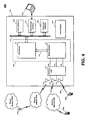
- FIG. 4 illustrates an embodiment of a system 400.
- This system may be suitable for use with one or more embodiments described herein, such as apparatus 100, implementation 200, logic flow 300, and so forth. Accordingly, system 400 may engage in wireless communications across various link types, such as the ones described herein. In addition, system 400 may perform various applications.
- system 400 may include a device 402, such as a mobile telephone, smartphone, personal digital assistant (PDA), notebook computer, and so forth. Further, system 400 includes multiple communications networks 404, as well as one or more remote devices 406.
- a device 402 such as a mobile telephone, smartphone, personal digital assistant (PDA), notebook computer, and so forth.
- system 400 includes multiple communications networks 404, as well as one or more remote devices 406.
- FIG. 4 shows that device 402 may include the elements of FIG. 1 .
- device 402 may include a radio frequency (RF) front end 407, a user interface 408, interconnection medium 410, a wired communications interface 412, a power supply (e.g., a battery) 414, and an expansion interface 416.
- RF radio frequency
- FIG. 4 shows that device 402 may include the elements of FIG. 1 .
- device 402 may include a radio frequency (RF) front end 407, a user interface 408, interconnection medium 410, a wired communications interface 412, a power supply (e.g., a battery) 414, and an expansion interface 416.
- RF radio frequency
- RF front end 407 is coupled to modem module 104.
- RF front end 407 may include components (e.g., amplifiers, filters, antennas, diplexers, and so forth) to prepare modulated signals for transmission and to prepare received signals for demodulation.
- FIG. 4 shows multiple connections (420, 422, and 424) between modem module 104 and RF front end 407. Each of these connections may be to a particular modem within modem module 104. For instance, connection 422a may be to modem 122a, connection 422b may be to modem 122b, and connection 422c may be to modem 122c. Further, FIG. 4 shows multiple antennas (426, 428, and 430) that may exchange wireless signals with remote devices. These antennas may correspond to a particular connection between RF front end 407 and modem module 104. For instance, antenna 426 may correspond to connection 420, antenna 428 may correspond to connection 422, and antenna 430 may correspond to connection 424. The embodiments, however, are not limited to these arrangements of connections and antennas.
- FIG. 4 shows that device 402 may communicate across wireless networks 404a-c.
- Wireless network 404a may be a wireless data network
- wireless network 404b may be a cellular network
- wireless network 404c may be an ad-hoc proximity network. The embodiments, however, are not limited to these examples.
- FIG. 4 shows wireless network 404b providing wireless communications (e.g., WLAN and/or WMAN communications) with an access point 406a.
- access point 406a may provide device 402 with access to further communications resources.
- FIG. 4 shows access point 406a providing access to a packet network 404d, such as the Internet.
- FIG. 4 shows wireless network 404b providing wireless communications (e.g., cellular telephony or messaging) with a mobile device 406b. Further, FIG. 4 shows device 402 communicating across wireless network 404c (e.g., a Bluetooth link) with a device 406c.
- wireless network 404b providing wireless communications (e.g., cellular telephony or messaging)
- device 402 communicating across wireless network 404c (e.g., a Bluetooth link) with a device 406c.
- User interface 408 facilitates user interaction with apparatus 100. This interaction may involve the input of information from a user and/or the output of information to a user. Accordingly, user interface 104 may include one or more devices, such as a keyboard (e.g., a full QWERTY keyboard), a keypad, a touch screen, a microphone, and/or an audio speaker. The embodiments are not limited to these examples.
- Interconnection medium 410 provides for couplings among elements, such as host device 102, user interface 408, wired communications interface 412, and/or expansion interface 416.
- interconnection medium 410 may include, for example, one or more bus interfaces. Exemplary interfaces include Universal Serial Bus (USB) interfaces, as well as various computer system bus interfaces. Additionally or alternatively, interconnection medium 410 may include one or more point-to-point connections (e.g., parallel interfaces, serial interfaces, etc.) between various element pairings. Such connections may comprise one or more signal lines.
- interconnection medium 410 may include non-physical aspects. For instance, such interconnectivity may be implemented through messages passed between processes or software modules.
- Wired communications interface 412 provides for the exchange of information with a device 406d (e.g., a proximate device), such as a personal computer. This exchange of information may be across one or more wired connections. Examples of such connections include USB interfaces, parallel interfaces, and/or serial interfaces. In addition, interface 412 may provide for such exchanges across wireless connections(s). An infrared interface is an example of such a connection.
- the information exchanged with such proximate devices may include e-mail, calendar entries, contact information, as well as other information associated with personal information management applications. In addition, such information may include various application files, and content (e.g., audio, image, and/or video).
- Wired communications interface 412 may include various components, such as a transceiver and control logic to perform operations according to one or more communications protocols.
- communications interface 412 may include input/output (I/O) adapters, physical connectors to connect the I/O adapter with a corresponding communications medium.
- I/O input/output
- Expansion interface 416 may be in the form of an expansion slot, such as a secure digital (SD) slot. Accordingly, expansion interface 416 may accept memory, external radios (e.g., global positioning system (GPS), Bluetooth, WiFi radios, etc.), content, hard drives, and so forth. The embodiments, however, are not limited to SD slots. Other expansion interface or slot technology may include memory stick, compact flash (CF), as well as others.
- SD secure digital
- Power supply 414 provides operational power to elements of device 402. Accordingly, power supply 414 may include a battery. Such a battery may be rechargeable and/or removable. Alternatively or additionally, power supply 414 may include an interface to an external power source, such as an alternating current (AC) source. However, the embodiments are not limited to these examples.
- a battery may be rechargeable and/or removable.
- power supply 414 may include an interface to an external power source, such as an alternating current (AC) source.
- AC alternating current
- embodiments may communicate across various types of wireless links, such as data networking links, personal area networking (PAN) links, and/or links provided by cellular systems.
- wireless links such as data networking links, personal area networking (PAN) links, and/or links provided by cellular systems.
- Examples of data networking links include wireless local area network (WLAN) links, such as IEEE 802.11 WiFi links. Further examples include wireless metropolitan area (WMAN) links, such as IEEE 802.16 WIMAX links. Examples of PAN links include ad-hoc proximity network links, such as Bluetooth links. The embodiments, however, are not limited to these examples.
- Exemplary cellular systems include Code Division Multiple Access (CDMA) systems, Global System for Mobile Communications (GSM) systems, North American Digital Cellular (NADC) systems, Time Division Multiple Access (TDMA) systems, Extended-TDMA (E-TDMA) systems, Digital Advanced Mobile Phone Service (IS-136/TDMA), Narrowband Advanced Mobile Phone Service (NAMPS) systems, third generation (3G) systems such as Wide-band CDMA (WCDMA), CDMA-2000, Universal Mobile Telephone System (UMTS), cellular radiotelephone systems compliant with the Third-Generation Partnership Project (3GPP), and so forth.
- CDMA Code Division Multiple Access
- GSM Global System for Mobile Communications
- NADC North American Digital Cellular
- TDMA Time Division Multiple Access
- E-TDMA Extended-TDMA
- IS-136/TDMA Extended-TDMA
- NAMPS Narrowband Advanced Mobile Phone Service
- third generation (3G) systems such as Wide-band CDMA (WCDMA), CDMA-2000, Universal Mobile Telephone System (UMTS), cellular radiotelephone systems compliant with
- embodiments may include storage media, such as memory 204 and memory 212.
- storage media may be implemented in various ways.
- such storage media may include read-only memory (ROM), random-access memory (RAM), dynamic RAM (DRAM), Double-Data-Rate DRAM (DDRAM), synchronous DRAM (SDRAM), static RAM (SRAM), programmable ROM (PROM), erasable programmable ROM (EPROM), electrically erasable programmable ROM (EEPROM), flash memory, polymer memory such as ferroelectric polymer memory, ovonic memory, phase change or ferroelectric memory, silicon-oxide-nitride-oxide-silicon (SONOS) memory, magnetic or optical cards, or any other type of media suitable for storing information.
- ROM read-only memory
- RAM random-access memory
- DRAM dynamic RAM
- DDRAM Double-Data-Rate DRAM
- SDRAM synchronous DRAM
- SRAM static RAM
- PROM programmable ROM
- EPROM erasable programmable
- memory 204 and/or memory 212 may be included in other elements of embodiments.
- some or all of memory 204 may be included on a same integrated circuit or chip with elements of host device 102 (e.g., processor 202).
- some or all of memory 212 may be included on a same integrated circuit or chip with elements of modem module 104 (e.g., processor 210).
- some portion or all of such storage media may be disposed on an integrated circuit or other medium (e.g., a hard disk drive) that is external to such elements.
- a hard disk drive e.g., a hard disk drive
- Various embodiments may be implemented using hardware elements, software elements, or a combination of both.
- hardware elements may include processors, microprocessors, circuits, circuit elements (e.g., transistors, resistors, capacitors, inductors, and so forth), integrated circuits, application specific integrated circuits (ASIC), programmable logic devices (PLD), digital signal processors (DSP), field programmable gate array (FPGA), logic gates, registers, semiconductor device, chips, microchips, chip sets, and so forth.
- Examples of software may include software components, programs, applications, computer programs, application programs, system programs, machine programs, operating system software, middleware, firmware, software modules, routines, subroutines, functions, methods, procedures, software interfaces, application program interfaces (API), instruction sets, computing code, computer code, code segments, computer code segments, words, values, symbols, or any combination thereof. Determining whether an embodiment is implemented using hardware elements and/or software elements may vary in accordance with any number of factors, such as desired computational rate, power levels, heat tolerances, processing cycle budget, input data rates, output data rates, memory resources, data bus speeds and other design or performance constraints.
- Coupled and “connected” along with their derivatives. These terms are not intended as synonyms for each other. For example, some embodiments may be described using the terms “connected” and/or “coupled” to indicate that two or more elements are in direct physical or electrical contact with each other. The term “coupled,” however, may also mean that two or more elements are not in direct contact with each other, but yet still co-operate or interact with each other.
- Some embodiments may be implemented, for example, using a machine-readable medium or article which may store an instruction or a set of instructions that, if executed by a machine, may cause the machine to perform a method and/or operations in accordance with the embodiments.
- a machine may include, for example, any suitable processing platform, computing platform, computing device, processing device, computing system, processing system, computer, processor, or the like, and may be implemented using any suitable combination of hardware and/or software.
- the machine-readable medium or article may include, for example, any suitable type of memory unit, memory device, memory article, memory medium, storage device, storage article, storage medium and/or storage unit, for example, memory, removable or non-removable media, erasable or non-erasable media, writeable or re-writeable media, digital or analog media, hard disk, floppy disk, Compact Disk Read Only Memory (CD-ROM), Compact Disk Recordable (CD-R), Compact Disk Rewriteable (CD-RW), optical disk, magnetic media, magneto-optical media, removable memory cards or disks, various types of Digital Versatile Disk (DVD), a tape, a cassette, or the like.
- memory removable or non-removable media, erasable or non-erasable media, writeable or re-writeable media, digital or analog media, hard disk, floppy disk, Compact Disk Read Only Memory (CD-ROM), Compact Disk Recordable (CD-R), Compact Disk Rewriteable (CD-RW), optical disk, magnetic
- the instructions may include any suitable type of code, such as source code, compiled code, interpreted code, executable code, static code, dynamic code, encrypted code, and the like, implemented using any suitable high-level, low-level, object-oriented, visual, compiled and/or interpreted programming language.
Landscapes
- Engineering & Computer Science (AREA)
- Theoretical Computer Science (AREA)
- Physics & Mathematics (AREA)
- General Engineering & Computer Science (AREA)
- General Physics & Mathematics (AREA)
- Information Transfer Systems (AREA)
Claims (15)
- Vorrichtung (100), die Folgendes umfasst:ein Host-Gerät (102), das zum Betreiben mehrerer Benutzeranwendungen (110a-c) konfiguriert ist, wobei das Host-Gerät ein Verbindungshostmodul (118), mehrere Kommunikationsports (116a-c) und mehrere Datenschnittstellen (114a-c) beinhaltet;ein Modemmodul (104), das mehrere Moderne (122a-c) umfasst;eine serielle Verbindung (106) zum Übertragen von Informationen gemäß einer USB-Konvention zwischen dem Verbindungshostmodul und den mehreren Modemen, wobei die Informationen mehrere Datentypen umfassen, die mit den mehreren Benutzeranwendungen und Befehlen für die mehreren Moderne assoziiert sind;wobei jeder der mehreren Kommunikationsports und jede der mehreren Datenschnittstellen einem jeweiligen einen der mehreren Moderne entsprechen; und dadurch gekennzeichnet, dass:die genannte serielle Verbindung (106) mehrere Logikkanäle umfasst, die mit Signalpegeln für einen logisch tiefen Pegel und einen logisch hohen Pegel implementiert werden, wobei der logisch hohe Signalpegel kleiner ist als gemäß der USB-Konvention für logisch hohe Signale vorgegebene Transceiver-Signalpegel, um Informationen über die serielle Verbindung (106) mit logisch hohen Signalpegeln auszutauschen, die niedriger sind als gemäß der USB-Konvention für ein logisch hohes Signal vorgegebene Transceiver-Signale.
- Vorrichtung (100) nach Anspruch 1, die ferner ein Modemmanagementmodul (120) umfasst, das mit der seriellen Verbindung (106) gekoppelt ist, wobei das Modemmanagementmodul die Aufgabe hat, mehrere Endpunktsätze bereitzustellen, wobei jeder Endpunktsatz einem der mehreren Moderne (122a-c) entspricht und jeder Endpunktsatz einen oder mehrere Endpunkte umfasst.
- Vorrichtung (100) nach Anspruch 2, wobei jeder der mehreren Endpunktsätze Folgendes umfasst:einen ersten Endpunkt zum Empfangen von Daten zur Modulation;einen zweiten Endpunkt zum Bereitstellen von demodulierten Daten; undeinen dritten Endpunkt zum Empfangen von Befehlen.
- Vorrichtung (100) nach einem vorherigen Anspruch, wobei das Host-Gerät eine Befehlsmaschine (112) zum Erzeugen der Befehle für die mehreren Moderne (122a-c) beinhaltet.
- Vorrichtung (100) nach Anspruch 4, wobei die mehreren Kommunikationsports (116a-c) die Aufgabe haben, die Befehle von der Befehlsmaschine (112) zu empfangen und die Daten mit den mehreren Datenschnittstellen (114a-c) auszutauschen.
- Vorrichtung (100) nach Anspruch 5, wobei das Verbindungshostmodul (118) zwischen den mehreren Kommunikationsports (116a-c) und der seriellen Verbindung (106) geschaltet ist.
- Vorrichtung (100) nach einem vorherigen Anspruch, wobei die USB-Konvention eine USB 2.0 Konvention ist.
- Vorrichtung (100) nach einem vorherigen Anspruch, wobei das Host-Gerät (102) und das Modemmodul (104) in einem Benutzergerät enthalten sind.
- Vorrichtung (100) nach einem vorherigen Anspruch, wobei das Host-Gerät (102) eine oder mehrere integrierte Schaltungen beinhaltet und die serielle Verbindung (106) die Aufgabe hat, Signale auf Pegeln zu senden, die von den ein oder mehreren integrierten Schaltungen verwendet werden.
- Vorrichtung (100) nach einem vorherigen Anspruch, wobei das Modemmodul (104) in einer oder mehreren integrierten Schaltungen enthalten ist und die serielle Verbindung (106) die Aufgabe hat, Signale auf Pegeln zu senden, die von den ein oder mehreren integrierten Schaltungen verwendet werden.
- Vorrichtung (100) nach einem vorherigen Anspruch, wobei das Host-Gerät (102) und die mehreren Moderne (122a-c) mit unterschiedlichen Taktraten arbeiten.
- Vorrichtung (100) nach einem vorherigen Anspruch, wobei die serielle Verbindung (106) die Aufgabe hat, Informationen zwischen dem Host-Gerät (102) und den mehreren Modemen (122a-c) asynchron zu übertragen.
- Verfahren zum Betreiben eines Computergerätes, das Folgendes beinhaltet:Erzeugen, an einem Host-Gerät (102), das zum Betreiben mehrerer Benutzeranwendungen (110a-c), eines Verbindungshostmoduls (118), mehrerer Kommunikationsports (116a-c) und mehrerer Datenschnittstellen (114a-c) konfiguriert ist, von mit einer ersten Anwendung assoziierten ersten Daten und von mit einer zweiten Anwendung assoziierten zweiten Daten, wobei die ersten Daten von einem ersten Modem (122a; 122b; 122c) moduliert werden, das einem ersten Kommunikationsport und einer ersten Datenschnittstelle entspricht, und die zweiten Daten von einem zweiten Modem (122b oder 122c; 122a oder 122c; 122a oder 122b) moduliert werden, das einem zweiten Kommunikationsport und einer zweiten Kommunikationsschnittstelle entspricht;Erzeugen, an dem Host-Gerät, eines ersten Befehls für das erste Modem und eines zweiten Befehls für das zweite Modem; undSenden der ersten Daten, der zweiten Daten, des ersten Befehls und des zweiten Befehls über eine serielle Verbindung (106), wobei sich die serielle Verbindung zwischen dem Verbindungshostmodul des Host-Geräts und einem Modemmodul (104) befindet, das das erste und zweite Modem umfasst; und dadurch gekennzeichnet, dass:die genannte serielle Verbindung (106) mehrere Logikkanäle umfasst, die mit Signalpegeln für einen logisch tiefen Pegel und einen logisch hohen Pegel implementiert werden, wobei der logisch hohe Signalpegel geringer ist als gemäß der USB-Konvention für logisch hohe Signale vorgegebene Transceiver-Signalpegel, um Informationen über die serielle Verbindung (106) mit logisch hohen Signalpegeln auszutauschen, die niedriger sind als gemäß der USB-Konvention für logisch hohe Signale vorgegebene Transceiver-Signale.
- Verfahren nach Anspruch 13, das ferner Folgendes beinhaltet:Empfangen, an dem Host-Gerät (102), von dritten Daten über die serielle Verbindung (106) von dem ersten Modem (122a; 122b; 122c), wobei die dritten Daten mit der ersten Anwendung assoziiert sind; undEmpfangen, an dem Host-Gerät, von vierten Daten über die serielle Verbindung von dem ersten Modem, wobei die vierten Daten mit der ersten Anwendung assoziiert sind.
- Artikel, der ein maschinen- oder computerlesbares Speichermedium umfasst, das Anweisungen enthält, die bei Ausführung ein System befähigen, das Verfahren nach Anspruch 13 oder 14 auszuführen.
Applications Claiming Priority (2)
| Application Number | Priority Date | Filing Date | Title |
|---|---|---|---|
| US11/772,209 US8260971B2 (en) | 2007-06-30 | 2007-06-30 | Techniques to exchange information for multiple modems |
| PCT/US2008/068175 WO2009006154A1 (en) | 2007-06-30 | 2008-06-25 | Interface for multiple modems |
Publications (3)
| Publication Number | Publication Date |
|---|---|
| EP2174232A1 EP2174232A1 (de) | 2010-04-14 |
| EP2174232A4 EP2174232A4 (de) | 2011-10-26 |
| EP2174232B1 true EP2174232B1 (de) | 2015-07-15 |
Family
ID=40162083
Family Applications (1)
| Application Number | Title | Priority Date | Filing Date |
|---|---|---|---|
| EP08771918.3A Not-in-force EP2174232B1 (de) | 2007-06-30 | 2008-06-25 | Schnittstelle für mehrere modems |
Country Status (3)
| Country | Link |
|---|---|
| US (1) | US8260971B2 (de) |
| EP (1) | EP2174232B1 (de) |
| WO (1) | WO2009006154A1 (de) |
Families Citing this family (5)
| Publication number | Priority date | Publication date | Assignee | Title |
|---|---|---|---|---|
| US8463976B2 (en) * | 2009-06-23 | 2013-06-11 | Lg Electronics Inc. | Dual modem device and controlling method thereof |
| US8930585B2 (en) * | 2012-05-29 | 2015-01-06 | Mediatek Inc. | USB host controller and scheduling methods thereof |
| US10091251B2 (en) * | 2013-04-04 | 2018-10-02 | Nvidia Corporation | Establishing communications |
| US9419846B2 (en) * | 2014-01-03 | 2016-08-16 | Honeywell International Inc. | Integrated wireless module |
| US10164888B2 (en) * | 2015-05-20 | 2018-12-25 | Intel IP Corporation | Quality of service for a universal serial bus |
Family Cites Families (19)
| Publication number | Priority date | Publication date | Assignee | Title |
|---|---|---|---|---|
| US6031867A (en) | 1993-07-02 | 2000-02-29 | Multi-Tech Systems, Inc. | Modem with firmware upgrade feature |
| US5809070A (en) * | 1996-02-27 | 1998-09-15 | Flat Connections, Inc. | High speed data communications using multiple low speed modems |
| FI102923B1 (fi) | 1996-08-08 | 1999-03-15 | Nokia Mobile Phones Ltd | Tiedontulostusjärjestelmä, menetelmä tiedon tulostamiseksi sekä päätelaitteet tiedon tulostamiseksi |
| GB2342535A (en) | 1998-10-09 | 2000-04-12 | Ericsson Telefon Ab L M | A modular radio telecommunications terminal |
| US6356582B1 (en) | 1998-11-20 | 2002-03-12 | Micrel, Incorporated | Universal serial bus transceiver |
| US6577622B1 (en) | 1999-09-27 | 2003-06-10 | 3Com Corp. | System and method for using a portable information device to establish a conference call on a telephony network |
| US6553240B1 (en) | 1999-12-30 | 2003-04-22 | Nokia Corporation | Print option for WAP browsers |
| AU2001265223A1 (en) * | 2000-05-31 | 2001-12-11 | Westell Technologies, Inc. | Modem having flexible architecture for connecting to multiple channel interfaces |
| WO2002037737A2 (en) * | 2000-11-01 | 2002-05-10 | Engi, Inc. | Wireless data input engine |
| US6745047B1 (en) | 2001-03-07 | 2004-06-01 | Palmone, Inc. | System and method for using a wireless enabled portable computer system as a wireless modem |
| US7131575B1 (en) * | 2001-03-26 | 2006-11-07 | Usa Technologies, Inc. | MDB transaction string effectuated cashless vending |
| US6600421B2 (en) | 2001-07-31 | 2003-07-29 | Koninklijke Philips Electronics N.V. | System to automatically locally control a device according to preferences of a user entering a local area of the device from a remote area |
| US7319715B1 (en) * | 2001-12-21 | 2008-01-15 | Novatel Wireless, Inc. | Systems and methods for a multi-mode wireless modem |
| US6795872B2 (en) * | 2002-05-09 | 2004-09-21 | Renesas Technology America, Inc. | Maintaining at least partial functionality of a device as defined by a hardware configuration at a USB bus enumeration while the device memory is programmed |
| US7065367B2 (en) | 2002-07-11 | 2006-06-20 | Oliver Michaelis | Interface selection in a wireless communication network |
| US7546372B2 (en) * | 2002-07-11 | 2009-06-09 | Ibeam Systems, Inc. | System and method for providing to multiple user computers concurrent telephonic access to multiple remote devices |
| US7664027B2 (en) * | 2004-10-20 | 2010-02-16 | Sigmatel, Inc. | Infrared adapter with data packet throttle |
| US20060176942A1 (en) | 2005-02-07 | 2006-08-10 | Vladimir Oksman | On-line reconfiguration and synchronization protocol for multi-carrier DSL |
| US7987380B2 (en) * | 2007-03-27 | 2011-07-26 | Atmel Rousset S.A.S. | Methods and apparatus to detect voltage class of a circuit |
-
2007
- 2007-06-30 US US11/772,209 patent/US8260971B2/en not_active Expired - Fee Related
-
2008
- 2008-06-25 EP EP08771918.3A patent/EP2174232B1/de not_active Not-in-force
- 2008-06-25 WO PCT/US2008/068175 patent/WO2009006154A1/en not_active Ceased
Also Published As
| Publication number | Publication date |
|---|---|
| US20090006703A1 (en) | 2009-01-01 |
| EP2174232A1 (de) | 2010-04-14 |
| WO2009006154A1 (en) | 2009-01-08 |
| EP2174232A4 (de) | 2011-10-26 |
| US8260971B2 (en) | 2012-09-04 |
Similar Documents
| Publication | Publication Date | Title |
|---|---|---|
| KR101840620B1 (ko) | 광학 매체에 대한 저전력 모드 신호 브릿지 | |
| US8036683B2 (en) | Coordination among multiple co-located radio modules | |
| EP2174232B1 (de) | Schnittstelle für mehrere modems | |
| KR20090091343A (ko) | 통합된 통신 및 정보 처리 시스템 | |
| US6931470B2 (en) | Dual access serial peripheral interface | |
| US20120054389A1 (en) | USB To I2C And SPI Bridge | |
| KR102613449B1 (ko) | Pcie(pci(peripheral component interconnect) express) 링크에서의 측파대 시그널링 | |
| WO2004023268A9 (en) | Method and apparatus for double data rate serial ata phy interface | |
| CN110334044B (zh) | 一种mipi dphy发送电路及设备 | |
| WO2020239102A1 (zh) | 一种接收电路、接收电路的重构方法及电子设备 | |
| CN102202132B (zh) | 一种对上网设备进行初始化的方法、系统及设备 | |
| CN114978916A (zh) | 一种数据传输带宽的配置方法及相关设备 | |
| CN110795382A (zh) | 一种基于fpga的通用异步收发传输器以及片上系统 | |
| CN103488598B (zh) | 一种多模终端及其实现usb共用的方法 | |
| EP4116835B1 (de) | Spreizspektrum-taktverhandlungsverfahren und expressvorrichtung und system für peripheriekomponentenverbindung | |
| CN113641610A (zh) | 处理器接口电路及处理器接口分时复用方法、电子设备 | |
| CN101561791B (zh) | 一种帧宽度可扩展的同步串行接口装置 | |
| CN115952120A (zh) | 一种接口转接装置、主板接口扩展电路及计算机设备 | |
| US20030104826A1 (en) | External connection device with bluetooth function in multiple modes | |
| CN113918503A (zh) | 发送电路、电子器件、芯片和电子设备 | |
| CN208190652U (zh) | 一种全双工通用同步异步串行收发器的主板 | |
| CN212364992U (zh) | 接口转换电路及接口转换装置 | |
| CN119988289A (zh) | 一种兼容性通信系统、方法及介质 | |
| RU24061U1 (ru) | Устройство для преобразования сигналов специальное | |
| KR20070010945A (ko) | 피디에이에서 호스트 씨피유와 주변 기기 간의 에스피아이통신 방법 및 시스템 |
Legal Events
| Date | Code | Title | Description |
|---|---|---|---|
| PUAI | Public reference made under article 153(3) epc to a published international application that has entered the european phase |
Free format text: ORIGINAL CODE: 0009012 |
|
| 17P | Request for examination filed |
Effective date: 20091222 |
|
| AK | Designated contracting states |
Kind code of ref document: A1 Designated state(s): AT BE BG CH CY CZ DE DK EE ES FI FR GB GR HR HU IE IS IT LI LT LU LV MC MT NL NO PL PT RO SE SI SK TR |
|
| AX | Request for extension of the european patent |
Extension state: AL BA MK RS |
|
| DAX | Request for extension of the european patent (deleted) | ||
| RAP1 | Party data changed (applicant data changed or rights of an application transferred) |
Owner name: HEWLETT-PACKARD DEVELOPMENT COMPANY, L.P. |
|
| REG | Reference to a national code |
Ref country code: DE Ref legal event code: R079 Ref document number: 602008039043 Country of ref document: DE Free format text: PREVIOUS MAIN CLASS: G06F0015160000 Ipc: G06F0013380000 |
|
| A4 | Supplementary search report drawn up and despatched |
Effective date: 20110922 |
|
| RIC1 | Information provided on ipc code assigned before grant |
Ipc: H04W 88/06 20090101ALN20110916BHEP Ipc: G06F 13/38 20060101AFI20110916BHEP |
|
| 17Q | First examination report despatched |
Effective date: 20130314 |
|
| RAP1 | Party data changed (applicant data changed or rights of an application transferred) |
Owner name: QUALCOMM INCORPORATED |
|
| GRAP | Despatch of communication of intention to grant a patent |
Free format text: ORIGINAL CODE: EPIDOSNIGR1 |
|
| INTG | Intention to grant announced |
Effective date: 20150121 |
|
| GRAS | Grant fee paid |
Free format text: ORIGINAL CODE: EPIDOSNIGR3 |
|
| GRAA | (expected) grant |
Free format text: ORIGINAL CODE: 0009210 |
|
| AK | Designated contracting states |
Kind code of ref document: B1 Designated state(s): AT BE BG CH CY CZ DE DK EE ES FI FR GB GR HR HU IE IS IT LI LT LU LV MC MT NL NO PL PT RO SE SI SK TR |
|
| REG | Reference to a national code |
Ref country code: CH Ref legal event code: EP Ref country code: GB Ref legal event code: FG4D |
|
| REG | Reference to a national code |
Ref country code: IE Ref legal event code: FG4D |
|
| REG | Reference to a national code |
Ref country code: AT Ref legal event code: REF Ref document number: 737122 Country of ref document: AT Kind code of ref document: T Effective date: 20150815 |
|
| REG | Reference to a national code |
Ref country code: DE Ref legal event code: R096 Ref document number: 602008039043 Country of ref document: DE |
|
| REG | Reference to a national code |
Ref country code: AT Ref legal event code: MK05 Ref document number: 737122 Country of ref document: AT Kind code of ref document: T Effective date: 20150715 |
|
| REG | Reference to a national code |
Ref country code: NL Ref legal event code: MP Effective date: 20150715 |
|
| REG | Reference to a national code |
Ref country code: LT Ref legal event code: MG4D |
|
| PG25 | Lapsed in a contracting state [announced via postgrant information from national office to epo] |
Ref country code: NO Free format text: LAPSE BECAUSE OF FAILURE TO SUBMIT A TRANSLATION OF THE DESCRIPTION OR TO PAY THE FEE WITHIN THE PRESCRIBED TIME-LIMIT Effective date: 20151015 Ref country code: LT Free format text: LAPSE BECAUSE OF FAILURE TO SUBMIT A TRANSLATION OF THE DESCRIPTION OR TO PAY THE FEE WITHIN THE PRESCRIBED TIME-LIMIT Effective date: 20150715 Ref country code: FI Free format text: LAPSE BECAUSE OF FAILURE TO SUBMIT A TRANSLATION OF THE DESCRIPTION OR TO PAY THE FEE WITHIN THE PRESCRIBED TIME-LIMIT Effective date: 20150715 Ref country code: LV Free format text: LAPSE BECAUSE OF FAILURE TO SUBMIT A TRANSLATION OF THE DESCRIPTION OR TO PAY THE FEE WITHIN THE PRESCRIBED TIME-LIMIT Effective date: 20150715 Ref country code: GR Free format text: LAPSE BECAUSE OF FAILURE TO SUBMIT A TRANSLATION OF THE DESCRIPTION OR TO PAY THE FEE WITHIN THE PRESCRIBED TIME-LIMIT Effective date: 20151016 |
|
| PG25 | Lapsed in a contracting state [announced via postgrant information from national office to epo] |
Ref country code: SE Free format text: LAPSE BECAUSE OF FAILURE TO SUBMIT A TRANSLATION OF THE DESCRIPTION OR TO PAY THE FEE WITHIN THE PRESCRIBED TIME-LIMIT Effective date: 20150715 Ref country code: PT Free format text: LAPSE BECAUSE OF FAILURE TO SUBMIT A TRANSLATION OF THE DESCRIPTION OR TO PAY THE FEE WITHIN THE PRESCRIBED TIME-LIMIT Effective date: 20151116 Ref country code: AT Free format text: LAPSE BECAUSE OF FAILURE TO SUBMIT A TRANSLATION OF THE DESCRIPTION OR TO PAY THE FEE WITHIN THE PRESCRIBED TIME-LIMIT Effective date: 20150715 Ref country code: HR Free format text: LAPSE BECAUSE OF FAILURE TO SUBMIT A TRANSLATION OF THE DESCRIPTION OR TO PAY THE FEE WITHIN THE PRESCRIBED TIME-LIMIT Effective date: 20150715 Ref country code: ES Free format text: LAPSE BECAUSE OF FAILURE TO SUBMIT A TRANSLATION OF THE DESCRIPTION OR TO PAY THE FEE WITHIN THE PRESCRIBED TIME-LIMIT Effective date: 20150715 Ref country code: PL Free format text: LAPSE BECAUSE OF FAILURE TO SUBMIT A TRANSLATION OF THE DESCRIPTION OR TO PAY THE FEE WITHIN THE PRESCRIBED TIME-LIMIT Effective date: 20150715 |
|
| REG | Reference to a national code |
Ref country code: DE Ref legal event code: R097 Ref document number: 602008039043 Country of ref document: DE |
|
| PG25 | Lapsed in a contracting state [announced via postgrant information from national office to epo] |
Ref country code: IT Free format text: LAPSE BECAUSE OF FAILURE TO SUBMIT A TRANSLATION OF THE DESCRIPTION OR TO PAY THE FEE WITHIN THE PRESCRIBED TIME-LIMIT Effective date: 20150715 Ref country code: EE Free format text: LAPSE BECAUSE OF FAILURE TO SUBMIT A TRANSLATION OF THE DESCRIPTION OR TO PAY THE FEE WITHIN THE PRESCRIBED TIME-LIMIT Effective date: 20150715 Ref country code: SK Free format text: LAPSE BECAUSE OF FAILURE TO SUBMIT A TRANSLATION OF THE DESCRIPTION OR TO PAY THE FEE WITHIN THE PRESCRIBED TIME-LIMIT Effective date: 20150715 Ref country code: CZ Free format text: LAPSE BECAUSE OF FAILURE TO SUBMIT A TRANSLATION OF THE DESCRIPTION OR TO PAY THE FEE WITHIN THE PRESCRIBED TIME-LIMIT Effective date: 20150715 Ref country code: DK Free format text: LAPSE BECAUSE OF FAILURE TO SUBMIT A TRANSLATION OF THE DESCRIPTION OR TO PAY THE FEE WITHIN THE PRESCRIBED TIME-LIMIT Effective date: 20150715 |
|
| PLBE | No opposition filed within time limit |
Free format text: ORIGINAL CODE: 0009261 |
|
| STAA | Information on the status of an ep patent application or granted ep patent |
Free format text: STATUS: NO OPPOSITION FILED WITHIN TIME LIMIT |
|
| PG25 | Lapsed in a contracting state [announced via postgrant information from national office to epo] |
Ref country code: RO Free format text: LAPSE BECAUSE OF FAILURE TO SUBMIT A TRANSLATION OF THE DESCRIPTION OR TO PAY THE FEE WITHIN THE PRESCRIBED TIME-LIMIT Effective date: 20150715 |
|
| 26N | No opposition filed |
Effective date: 20160418 |
|
| PG25 | Lapsed in a contracting state [announced via postgrant information from national office to epo] |
Ref country code: IS Free format text: LAPSE BECAUSE OF FAILURE TO SUBMIT A TRANSLATION OF THE DESCRIPTION OR TO PAY THE FEE WITHIN THE PRESCRIBED TIME-LIMIT Effective date: 20150715 |
|
| PG25 | Lapsed in a contracting state [announced via postgrant information from national office to epo] |
Ref country code: SI Free format text: LAPSE BECAUSE OF FAILURE TO SUBMIT A TRANSLATION OF THE DESCRIPTION OR TO PAY THE FEE WITHIN THE PRESCRIBED TIME-LIMIT Effective date: 20150715 |
|
| PG25 | Lapsed in a contracting state [announced via postgrant information from national office to epo] |
Ref country code: BE Free format text: LAPSE BECAUSE OF FAILURE TO SUBMIT A TRANSLATION OF THE DESCRIPTION OR TO PAY THE FEE WITHIN THE PRESCRIBED TIME-LIMIT Effective date: 20150715 |
|
| PG25 | Lapsed in a contracting state [announced via postgrant information from national office to epo] |
Ref country code: MC Free format text: LAPSE BECAUSE OF FAILURE TO SUBMIT A TRANSLATION OF THE DESCRIPTION OR TO PAY THE FEE WITHIN THE PRESCRIBED TIME-LIMIT Effective date: 20150715 |
|
| REG | Reference to a national code |
Ref country code: CH Ref legal event code: PL |
|
| REG | Reference to a national code |
Ref country code: IE Ref legal event code: MM4A |
|
| REG | Reference to a national code |
Ref country code: FR Ref legal event code: ST Effective date: 20170228 |
|
| PG25 | Lapsed in a contracting state [announced via postgrant information from national office to epo] |
Ref country code: CH Free format text: LAPSE BECAUSE OF NON-PAYMENT OF DUE FEES Effective date: 20160630 Ref country code: FR Free format text: LAPSE BECAUSE OF NON-PAYMENT OF DUE FEES Effective date: 20160630 Ref country code: LI Free format text: LAPSE BECAUSE OF NON-PAYMENT OF DUE FEES Effective date: 20160630 |
|
| PG25 | Lapsed in a contracting state [announced via postgrant information from national office to epo] |
Ref country code: IE Free format text: LAPSE BECAUSE OF NON-PAYMENT OF DUE FEES Effective date: 20160625 |
|
| PG25 | Lapsed in a contracting state [announced via postgrant information from national office to epo] |
Ref country code: NL Free format text: LAPSE BECAUSE OF FAILURE TO SUBMIT A TRANSLATION OF THE DESCRIPTION OR TO PAY THE FEE WITHIN THE PRESCRIBED TIME-LIMIT Effective date: 20150715 |
|
| REG | Reference to a national code |
Ref country code: DE Ref legal event code: R082 Ref document number: 602008039043 Country of ref document: DE Representative=s name: MAUCHER JENKINS, DE Ref country code: DE Ref legal event code: R082 Ref document number: 602008039043 Country of ref document: DE Representative=s name: MAUCHER JENKINS PATENTANWAELTE & RECHTSANWAELT, DE |
|
| PGFP | Annual fee paid to national office [announced via postgrant information from national office to epo] |
Ref country code: DE Payment date: 20170623 Year of fee payment: 10 |
|
| PG25 | Lapsed in a contracting state [announced via postgrant information from national office to epo] |
Ref country code: HU Free format text: LAPSE BECAUSE OF FAILURE TO SUBMIT A TRANSLATION OF THE DESCRIPTION OR TO PAY THE FEE WITHIN THE PRESCRIBED TIME-LIMIT; INVALID AB INITIO Effective date: 20080625 Ref country code: CY Free format text: LAPSE BECAUSE OF FAILURE TO SUBMIT A TRANSLATION OF THE DESCRIPTION OR TO PAY THE FEE WITHIN THE PRESCRIBED TIME-LIMIT Effective date: 20150715 |
|
| PG25 | Lapsed in a contracting state [announced via postgrant information from national office to epo] |
Ref country code: LU Free format text: LAPSE BECAUSE OF NON-PAYMENT OF DUE FEES Effective date: 20160625 Ref country code: TR Free format text: LAPSE BECAUSE OF FAILURE TO SUBMIT A TRANSLATION OF THE DESCRIPTION OR TO PAY THE FEE WITHIN THE PRESCRIBED TIME-LIMIT Effective date: 20150715 Ref country code: MT Free format text: LAPSE BECAUSE OF NON-PAYMENT OF DUE FEES Effective date: 20160630 |
|
| PG25 | Lapsed in a contracting state [announced via postgrant information from national office to epo] |
Ref country code: BG Free format text: LAPSE BECAUSE OF FAILURE TO SUBMIT A TRANSLATION OF THE DESCRIPTION OR TO PAY THE FEE WITHIN THE PRESCRIBED TIME-LIMIT Effective date: 20150715 |
|
| PGFP | Annual fee paid to national office [announced via postgrant information from national office to epo] |
Ref country code: GB Payment date: 20180403 Year of fee payment: 11 |
|
| REG | Reference to a national code |
Ref country code: DE Ref legal event code: R119 Ref document number: 602008039043 Country of ref document: DE |
|
| PG25 | Lapsed in a contracting state [announced via postgrant information from national office to epo] |
Ref country code: DE Free format text: LAPSE BECAUSE OF NON-PAYMENT OF DUE FEES Effective date: 20190101 |
|
| GBPC | Gb: european patent ceased through non-payment of renewal fee |
Effective date: 20190625 |
|
| PG25 | Lapsed in a contracting state [announced via postgrant information from national office to epo] |
Ref country code: GB Free format text: LAPSE BECAUSE OF NON-PAYMENT OF DUE FEES Effective date: 20190625 |