EP2170537B1 - Flexibler niederhalter für eine profilieranlage zum flexiblen walzprofilieren von kalt- oder warmprofilen mit veränderlichem querschnitt - Google Patents
Flexibler niederhalter für eine profilieranlage zum flexiblen walzprofilieren von kalt- oder warmprofilen mit veränderlichem querschnitt Download PDFInfo
- Publication number
- EP2170537B1 EP2170537B1 EP08785118A EP08785118A EP2170537B1 EP 2170537 B1 EP2170537 B1 EP 2170537B1 EP 08785118 A EP08785118 A EP 08785118A EP 08785118 A EP08785118 A EP 08785118A EP 2170537 B1 EP2170537 B1 EP 2170537B1
- Authority
- EP
- European Patent Office
- Prior art keywords
- profiling
- metal sheet
- assemblies
- clamping
- sheet
- Prior art date
- Legal status (The legal status is an assumption and is not a legal conclusion. Google has not performed a legal analysis and makes no representation as to the accuracy of the status listed.)
- Not-in-force
Links
- 238000009434 installation Methods 0.000 title claims abstract 12
- 239000002184 metal Substances 0.000 claims abstract description 26
- 238000000034 method Methods 0.000 claims abstract description 17
- 230000000712 assembly Effects 0.000 claims description 19
- 238000000429 assembly Methods 0.000 claims description 19
- 238000005096 rolling process Methods 0.000 claims description 4
- 230000000284 resting effect Effects 0.000 claims 2
- 239000002689 soil Substances 0.000 description 6
- 230000006978 adaptation Effects 0.000 description 1
- 238000011161 development Methods 0.000 description 1
- 230000018109 developmental process Effects 0.000 description 1
- 230000000670 limiting effect Effects 0.000 description 1
- 239000000463 material Substances 0.000 description 1
- 238000011144 upstream manufacturing Methods 0.000 description 1
Images


Classifications
-
- B—PERFORMING OPERATIONS; TRANSPORTING
- B21—MECHANICAL METAL-WORKING WITHOUT ESSENTIALLY REMOVING MATERIAL; PUNCHING METAL
- B21D—WORKING OR PROCESSING OF SHEET METAL OR METAL TUBES, RODS OR PROFILES WITHOUT ESSENTIALLY REMOVING MATERIAL; PUNCHING METAL
- B21D5/00—Bending sheet metal along straight lines, e.g. to form simple curves
- B21D5/06—Bending sheet metal along straight lines, e.g. to form simple curves by drawing procedure making use of dies or forming-rollers, e.g. making profiles
- B21D5/08—Bending sheet metal along straight lines, e.g. to form simple curves by drawing procedure making use of dies or forming-rollers, e.g. making profiles making use of forming-rollers
- B21D5/083—Bending sheet metal along straight lines, e.g. to form simple curves by drawing procedure making use of dies or forming-rollers, e.g. making profiles making use of forming-rollers for obtaining profiles with changing cross-sectional configuration
-
- Y—GENERAL TAGGING OF NEW TECHNOLOGICAL DEVELOPMENTS; GENERAL TAGGING OF CROSS-SECTIONAL TECHNOLOGIES SPANNING OVER SEVERAL SECTIONS OF THE IPC; TECHNICAL SUBJECTS COVERED BY FORMER USPC CROSS-REFERENCE ART COLLECTIONS [XRACs] AND DIGESTS
- Y10—TECHNICAL SUBJECTS COVERED BY FORMER USPC
- Y10T—TECHNICAL SUBJECTS COVERED BY FORMER US CLASSIFICATION
- Y10T428/00—Stock material or miscellaneous articles
- Y10T428/12—All metal or with adjacent metals
- Y10T428/1241—Nonplanar uniform thickness or nonlinear uniform diameter [e.g., L-shape]
Definitions
- the invention relates to a profiling system for roll forming of cold or hot profiles with variable cross section and an associated method.
- rolls acting together in pairs provide a profile in the form of which a sheet to be formed is brought.
- the forming of the sheet takes place in several stages with multiple roller pairs or roll stands.
- the stepwise degree of deformation of the sheet is chosen such that the sheet is not undesirable stressed and deformed.
- a device for producing profiled sheets with variable cross section is from the DE 100 11 755 A1 known. This is a concept disclosed, in addition to the so far known when profiling adjustment transverse to the profiling additionally allows a rotational movement about the vertical axis. This concept is intended to remedy the disadvantages of those operating principles in which a tool movement in which the rollers lie tangentially against the sheet during the entire profiling is not possible. Due to the not exclusively transversely to the profile direction adjustment of the rollers a perfect deformation is to be achieved and unfavorable deformations are eliminated on the plate.
- a similar device for producing profiled sheets with variable cross section is from DE 10 2004 040 257 A1 known.
- the device has an additional roller and a support element, wherein the rollers and support elements of the mill stand to ensure that no inadmissible deformations occur on the plate.
- the object of the present invention is to eliminate the above-mentioned disadvantages of the prior art with regard to the undesired deformations during flexible profiling and to provide a reshaped product with a continuously defined and controlled height of the bottom.
- This object is achieved by a profiling system for roll profiling of cold or hot profiles with variable cross section and an associated method according to claim 1 or claim 9.
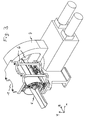
- the Fig. 1 shows a profiling with a flexible hold-1 of the present invention.
- the hold-down 1 includes an upper assembly 2 and a lower assembly 3 which clamp a sheet 5 to be profiled therebetween.
- the two arrangements 2, 3 are via an upper guide 2 d and a lower guide 3d in a frame 4th movably mounted.
- the upper assembly 2 includes a bracket 2c and an adjustable upper jaw 2a with an adjustable clamping shoe 2b.
- the lower assembly 3 includes a holder 3c and an adjustable lower jaw 3a.
- the guides 2d, 3d may be configured as a rail guide. And in another embodiment, the guides 2d, 3d may be configured as a roller guide. And in another embodiment, the guides 2d, 3d may be configured as dovetail guides, prism guides, narrow guides, or cylindrical guides.
- the configuration of the upper guide 2d can be different from that of the lower guide 3d.
- analogously to the upper clamping shoe it is also possible to provide a lower clamping shoe which can be functionally adapted like the upper clamping shoe.
- the adjustable upper jaw 2a can be advantageously pressed by a hydraulic leverage in a direction perpendicular to the sheet feed on the sheet to be profiled plate 5 and against the lower jaw 3a.
- only the jaw 2a is pressed against the sheet by means of a pneumatic or an electromagnetic leverage, the lower jaw 3a being adjustable by a screw to a predetermined height.
- the arrangements 2, 3 of the flexible blank holder 1 clamp the sheet on both sides from above and from below. In another embodiment, the arrangements 2, 3 clamp the sheet embracing on one or both legs 5a, 5b.
- the assemblies 2, 3 of the flexible Hold-down 1 in the frame 4 on the guides 2d, 3d passively with the sheet feed, ie without its own drive via motors, pulled along. As a result, no additional forces are introduced into the sheet during the profiling, so that a 100% match with the sheet feed is ensured.
- the arrangements 2, 3 in the frame 4 on the guides 2d, 3d in the direction of sheet metal advance active ie driven by a separate drive via motors. However, in this active entrainment of the arrangements 2, 3 a synchronization with the sheet feed is required. Also, combinations of active and passive guides are intended according to the invention.
- the Fig. 2 shows an upper assembly 2 with an adjustable upper jaw 2a with an adjustable clamping shoe 2b of the present invention.
- means are used to adapt the clamping shoe 2b during the profiling process in the feed plane (plane xz) or perpendicular to the feed plane (y direction). These means fit the clamping shoe 2b in the width, height, shape or position of the profile of the sheet, since in three-dimensional cross-sections, d. H. with height-adjustable floor, the arrangement 2 must follow the bottom of the profile and must adjust in height and inclination. If the sheet is bent on different sides with respect to the ground, it would be conceivable that these means act on the corresponding sides of the floor. By this adaptation, a collision with the legs 5a, 5b is avoided and the sheet is not exposed to undesirable deformations.
- the Fig. 3 shows a profiling with a flexible hold-1 according to the present invention.
- a method for profiling a sheet 5 using the profiling with the flexible hold-down. 1 includes the steps described below.
- the Fig. 3 only one mill stand is shown, but it will be readily understood by those skilled in the art that there are further mill stands upstream and downstream of the mill stand which are part of the profiling line.
- step 1 the sheet 5 to be profiled is clamped.
- the two assemblies 2, 3 press out of a starting position (rest position) at a defined point the profile of the sheet.
- This predetermined location is determined in advance depending on the type of deformation and the sheet material used and the geometry of the rolling mill.
- the sheet is clamped on both sides from above and from below.
- the sheet can be clamped around one or both legs 5a, 5b.
- all degrees of freedom must be suppressed to the degree of freedom of profiling, so that no relative movement between the sheet and hold-down is possible. As a result, unwanted deformations of the sheet can be excluded and a continuously defined and controlled height of the soil can be achieved.
- step 2 the clamped sheet 5 is guided during profiling while linearly guiding the assemblies 2, 3 in the profile direction.
- the arrangements 2, 3 move with the sheet 5 to be profiled as a unit.
- the arrangements 2, 3 can be passively pulled along with the sheet feed. The introduction of additional forces in the sheet is avoided and ensures 100% compliance with the sheet feed.
- the assemblies 2, 3 can be actively driven in the direction of the sheet metal feed via motors. In this entrainment of the arrangements 2, 3, however, a synchronization with the sheet feed is required: This can also unwanted deformations of the sheet excluded and a continuously defined and controlled height of the soil.
- the arrangements 2, 3 are brought as close as possible to the forming rollers 6 under clamping of the sheet in order to have the longest possible guide path of the sheet and as long as possible contact time with the sheet.
- the clamping shoe 2b can be adapted to the profile of the sheet 5 during the profiling process in terms of width, height, shape or position. This avoids a collision with the legs 5a, 5b.
- the arrangement 2 can thus follow the bottom of the profile and adapt in height and inclination. As a result, unwanted deformations of the sheet can also be excluded and a continuously defined and controlled height of the soil can be achieved.
- step 3 the clamping of the entrained arrangements 2, 3 is released when the clamped point reaches the next roll stand 7.
- step 4 the assemblies 2, 3 are returned to the home position (rest position). Thereafter, steps 1-4 can be performed again.
- sheets can be profiled, which do not have the mentioned disadvantages of the prior art.
- These sheets can be manufactured with consistent quality due to a continuously defined and controlled height of the ground, for example in the automotive industry, the possible applications not in this area are limited.
Landscapes
- Engineering & Computer Science (AREA)
- Mechanical Engineering (AREA)
- Bending Of Plates, Rods, And Pipes (AREA)
- Shaping Metal By Deep-Drawing, Or The Like (AREA)
- Switches With Compound Operations (AREA)
- Rehabilitation Tools (AREA)
- Tents Or Canopies (AREA)
- Lining Or Joining Of Plastics Or The Like (AREA)
Description
- Die Erfindung betrifft eine Profilieranlage zum Walzprofilieren von Kalt- oder Warmprofilen mit veränderlichem Querschnitt sowie ein dazugehöriges Verfahren.
- Beim Walzprofilieren geben paarweise zusammen wirkende Walzen ein Profil vor, in dessen Form ein umzuformendes Blech gebracht wird. Im Allgemeinen erfolgt die Umformung des Bleches in mehreren Stufen mit mehreren Walzenpaaren bzw. Walzengerüsten. Der stufenweise Umformungsgrad des Bleches wird derart gewählt, dass das Blech nicht unerwünscht beansprucht und verformt wird.
- Eine Vorrichtung zur Erzeugung von profilierten Blechen mit veränderlichem Querschnitt ist aus der
DE 100 11 755 A1 bekannt. Darin ist ein Konzept offenbart, das neben der bislang beim Profilieren bekannten Verstellmöglichkeit quer zur Profilierrichtung zusätzlich eine Drehbewegung um die vertikale Achse ermöglicht. Dieses Konzept soll die Nachteile derjenigen Funktionsprinzipien beheben, bei denen eine Werkzeugbewegung, bei der die Walzen während der gesamten Profilierung tangential am Blech anliegen, nicht möglich ist. Durch die nicht ausschliesslich quer zur Profilrichtung erfolgende Verstellung der Walzen sollen eine einwandfreie Umformung erzielt und ungünstige Verformungen am Blech beseitigt werden. - Eine ähnliche Vorrichtung zur Erzeugung von profilierten Blechen mit veränderlichem Querschnitt ist aus der
DE 10 2004 040 257 A1 bekannt. Die Vorrichtung verfügt über eine zusätzliche Wälze und ein Stützelement, wobei die Rollen und Stützelemente des Walzengerüstes sicherstellen sollen, dass keine unzulässigen Verformungen am Blech auftreten. - Trotz dieser Vorkehrungen zur Erzielung einer einwandfreien Umformung kommt es vor, dass unerwünschte Verformungen am Boden des zu profilierenden Bleches auftreten und zu Abweichungen von der Ideallinie des Bodens führen. Diese unerwünschten Verformungen haben zur Folge, dass eine kontinuierlich definierte und kontrollierte Höhe des Bodens nicht erzielt werden kann. Dadurch kommt es zu Abweichungen von der Ideallinie des Bodens, die zu inakzeptablen Schwankungen bei den Produkten führen.
- Die Aufgabe der vorliegenden Erfindung besteht darin, die oben erwähnten Nachteile des Standes der Technik hinsichtlich der unerwünschten Verformungen beim flexiblen Profilieren zu unterbinden und ein umgeformtes Produkt mit kontinuierlich definierter und kontrollierter Höhe des Bodens bereitzustellen. Diese Aufgabe wird durch eine Profilieranlage zum Walzprofilieren von Kalt-oder Warmprofilen mit veränderlichem Querschnitt sowie einem dazugehörigen Verfahren gemäß Anspruch 1 bzw. Anspruch 9 gelöst.
- Vorteilhafte Weiterbildungen der Erfindung sind in den anhängigen Ansprüchen gegeben.
-
-
Fig. 1 . zeigt eine Seitenansicht eines flexiblen Niederhalters. -
Fig. 2 zeigt eine perspektivische Ansicht einer oberen Anordnung des flexiblen Niederhalters derFig. 1 . mit einer verstellbaren oberen Klemmbacke 2a mit einem anpassbaren Klemmschuh 2b. -
Fig. 3 zeigt eine perspektivische Ansicht einer Profilieranlage mit einem flexiblen Niederhalter gemäß der vorliegenden Erfindung. - Die
Fig. 1 zeigt einer Profilieranlage mit einem flexiblen Niederhalter 1 der vorliegenden Erfindung. Der Niederhalter 1 schliesst eine obere Anordnung 2 und eine untere Anordnung 3 ein, die ein zu profilierendes Blech 5 zwischen sich klemmen. Die beiden Anordnungen 2, 3 sind über eine obere Führung 2d und eine untere Führung 3d in einem Rahmen 4 beweglich angebracht. - In einer Ausführungsform schliesst die obere Anordnung 2 eine Halterung 2c und eine verstellbare obere Klemmbacke 2a mit einem anpassbaren Klemmschuh 2b ein. Die untere Anordnung 3 schliesst eine Halterung 3c und eine verstellbare untere Klemmbacke 3a ein. Die Führungen 2d, 3d können als eine Schienenführung ausgestaltet sein. Und in einer anderen Ausführungsform können die Führungen 2d, 3d als eine Walzenführung ausgestaltet sein. Und in einer weiteren Ausführungsform können die Führungen 2d, 3d als Schwalbenschwanzführungen, Prismenführungen, Schmalführungen oder zylindrische Führungen ausgestaltet sein. Die Ausgestaltung der oberen Führung 2d kann dabei von der der unteren Führung 3d verschieden sein. Obwohl nicht gezeigt, kann analog zum oberen Klemmschuh auch ein unterer Klemmschuh vorgesehen sein, der funktionell wie der obere Klemmschuh angepasst werden kann.
- Die verstellbare obere Klemmbacke 2a kann vorteilhaft über eine hydraulische Hebelkraft in einer zum Blechvorschub senkrechten Richtung auf das zu profilierende Blech 5 und gegen die untere Klemmbacke 3a gepresst werden. In einer anderen Ausführungsform wird nur die Klemmbacke 2a über eine pneumatische oder eine elektromagnetische Hebelkraft gegen das Blech gepresst, wobei die untere Klemmbacke 3a durch eine Schraube auf eine vorgegebene Höhe einstellbar ist.
- In einer Ausführungsform klemmen die Anordnungen 2, 3 des flexiblen Niederhalters 1 das Blech beidseitig von oben und von unten. In einer anderen Ausführungsform klemmen die Anordnungen 2, 3 das Blech umgreifend an einem oder beiden Schenkeln 5a, 5b.
- In einer Ausführungsform werden die Anordnungen 2, 3 des flexiblen Niederhalters 1 in dem Rahmen 4 auf den Führungen 2d, 3d mit dem Blechvorschub passiv, d. h. ohne einen eigenen Antrieb über Motoren, mitgezogen. Dadurch werden während dem Profiliervorgang keine zusätzlichen Kräfte in das Blech eingeleitet, so dass eine 100%-ige Übereinstimmung mit dem Blechvorschub gewährleistet wird. In einer anderen Ausführungsform werden die Anordnungen 2, 3 in dem Rahmen 4 auf den Führungen 2d, 3d in Richtung des Blechvorschubs aktiv, d. h. mit einem eigenen Antrieb über Motoren, angetrieben. Allerdings ist bei dieser aktiven Mitführung der Anordnungen 2, 3 eine Synchronisation mit dem Blechvorschub erforderlich. Auch sind Kombinationen von aktiven und passiven Führungen erfindungsgemäß beabsichtigt.
- Die
Fig. 2 zeigt eine obere Anordnung 2 mit einer verstellbaren oberen Klemmbacke 2a mit einem anpassbaren Klemmschuh 2b der vorliegenden Erfindung. - Erfindungsgemäß werden Mittel verwendet, um den Klemmschuh 2b während des Profiliervorgangs in der Vorschubsebene (Ebene xz) oder senkrecht zur Vorschubsebene (y-Richtung) anzupassen. Diese Mittel passen den Klemmschuh 2b in der Breite, Höhe, Form oder Position an das Profil des Bleches an, da bei dreidimensionalen Querschnitten, d. h. mit höhenveränderlichem Boden, die Anordnung 2 dem Boden des Profils folgen und sich in der Höhe und Neigung anpassen muss. Falls das Blech an verschiedenen Seiten in Bezug auf den Boden gebogen wird, wäre denkbar, dass diese Mittel an den entsprechenden Seiten des Bodens wirken. Durch diese Anpassung wird eine Kollision mit den Schenkeln 5a, 5b vermieden und das Blech keinen unerwünschten Verformungen ausgesetzt.
- Die
Fig. 3 zeigt eine Profilieranlage mit einem flexiblen Niederhalter 1 gemäß der vorliegenden Erfindung. Ein Verfahren zum Profilieren eines Bleches 5 unter Verwendung der Profilieranlage mit dem flexiblen Niederhalter 1 schliesst die nachfolgend beschriebenen Schritte ein. In derFig. 3 wird nur ein Walzengerüst dargestellt, aber für den Fachmann ist es ohne weiteres verständlich, dass stromaufwärts und stromabwärts von dem Walzengerüst weitere Walzengerüste vorhanden sind, die Teil der Profilieranlage sind. - In dem Schritt 1 wird das zu profilierende Blech 5 geklemmt. Dazu pressen die beiden Anordnungen 2, 3 aus einer Ausgangsposition (Ruhelage) heraus an einer definierten Stelle das Profil des Bleches. Diese vorbestimmte Stelle wird im Voraus abhängig von der Art der Verformung und des verwendeten Blechmaterials sowie der Geometrie der Walzanlage bestimmt. Das Blech wird dabei beidseitig von oben und von unten geklemmt. Alternativ dazu kann das Blech umgreifend an einem oder beiden Schenkeln 5a, 5b geklemmt werden. Bei dem Klemmen des Bleches ist darauf zu achten, dass die Presskraft größer als die Verformungskraft der Klemmstelle ist. Ferner müssen sämtliche Freiheitsgrade bis auf den Freiheitsgrad der Profilierrichtung unterbunden werden, so dass keine Relativbewegung zwischen Blech und Niederhalter möglich ist. Dadurch können unerwünschte Verformungen des Bleches ausgeschlossen und eine kontinuierlich definierte und kontrollierte Höhe des Bodens erzielt werden.
- In dem Schritt 2 wird das geklemmte Blech 5 während der Profilierung unter linearem Mitführen der Anordnungen 2, 3 in Profilrichtung geführt. Dadurch bewegen sich die Anordnungen 2, 3 mit dem zu profilierenden Blech 5 als eine Einheit mit. Die Anordnungen 2, 3 können dabei mit dem Blechvorschub passiv mitgezogen werden. Die Einleitung von zusätzlichen Kräften in das Blech wird vermieden und eine 100%-ige Übereinstimmung mit dem Blechvorschub gewährleistet. Alternativ dazu können die Anordnungen 2, 3 in Richtung des Blechvorschubs aktiv über Motoren angetrieben werden. Bei dieser Mitführung der Anordnungen 2, 3 ist jedoch eine Synchronisation mit dem Blechvorschub erforderlich: Hierdurch können ebenfalls unerwünschte Verformungen des Bleches ausgeschlossen und eine kontinuierlich definierte und kontrollierte Höhe des Bodens erzielt werden.
- In diesem Schritt 2 ist es ferner bevorzugt, dass die Anordnungen 2, 3 unter Klemmung des Bleches möglichst nahe an die formenden Rollen 6 herangeführt werden, um einen möglichst langen Führungsweg des Bleches und eine möglichst lange Kontaktzeit mit dem Blech zu haben.
- Außerdem ist es in diesem Schritt 2 bei dreidimensionalen Querschnitten, also mit höhenveränderlichem Boden, ferner bevorzugt, dass der Klemmschuh 2b während des Profiliervorgangs in der Breite, Höhe, Form oder Position an das Profil des Bleches 5 angepasst werden kann. Hierdurch wird eine Kollision mit den Schenkeln 5a, 5b vermieden. Die Anordnung 2 kann somit dem Boden des Profils folgen und sich in der Höhe und Neigung anpassen. Dadurch können ebenfalls unerwünschte Verformungen des Bleches ausgeschlossen und eine kontinuierlich definierte und kontrollierte Höhe des Bodens erzielt werden.
- In dem Schritt 3 wird die Klemmung der mitgeführten Anordnungen 2, 3 gelöst, wenn die geklemmte Stelle das nächste Walzengerüst 7 erreicht.
- In dem Schritt 4 werden die Anordnungen 2, 3 in die Ausgangsposition (Ruhelage) zurück gebracht. Danach können die Schritte 1-4 erneut durchgeführt werden.
- Mit der vorstehend beschriebene Profilieranlage mit dem Niederhalter 1 der vorliegenden Erfindung, sowie dem erfindungsgemäßen Verfahren können Bleche profiliert werden, die die erwähnten Nachteile des Standes der Technik nicht aufweisen. Diese Bleche können bei gleich bleibender Qualität aufgrund einer kontinuierlich definierten und kontrollierten Höhe des Bodens beispielsweise in der Automobilindustrie hergestellt werden, wobei die Einsatzmöglichkeiten nicht auf dieses Gebiet beschränkt sind.
- Wenn in irgendeinem der Ansprüche erwähnte technische Merkmale mit einem Bezugszeichen versehen sind, wurden diese Bezugszeichen lediglich eingeschlossen, um die Verständlichkeit der Ansprüche zu erhöhen. Entsprechend haben diese Bezugszeichen keine einschränkende Auswirkung auf den Schutzumfang eines jeden Elements, das exemplarisch durch solche Bezugszeichen bezeichnet wird.
-
- 1
- flexibler Niederhalter
- 2
- obere Anordnung
- 2a
- verstellbare obere Klemmbacke
- 2b
- anpassbarer Klemmschuh
- 2c
- Halterung
- 2d
- obere Führung
- 3
- untere Anordnung
- 3a
- verstellbare untere Klemmbacke
- 3c
- Halterung
- 3d
- untere Führung
- 4
- Rahmen
- 5
- zu profilierendes Blech
- 5a
- Schenkel
- 5b
- Schenkel
- 6
- formende Rollen
- 7
- Walzengerüst
Claims (14)
- Profilieranlage zum Walzprofilieren von Kalt-oder Warmprofilen mit veränderlichen Querschnitt mit einem flexiblen Niederhalter (1) zum Klemmen eines zu profilierenden Bleches (5), der eine obere Anordnung (2) und eine untere Anordnung (3) umfasst, die in einem Rahmen (4) angebracht sind, das Blech (5) an einer definierten Stelle klemmen und in einem Freiheitsgrad beweglich sind, wobei
der flexible Niederhalter (1) vor oder hinter einem Walzengerüst (7) der Profilieranlage angeordnet ist, wobei die beiden Anordnungen (2, 3) in dem Rahmen (4) über eine obere Führung (2d) und eine untere Führung (3d) derart beweglich angebracht sind, dass sie sich synchron mit dem Blechvorschub bewegen, um sämtliche Freiheitsgrade bis auf den Freiheitsgrad der Profilierrichtung zu unterbinden. - Profilieranlage gemäß Anspruch 1, wobei
die obere Anordnung (2) eine Halterung (2c) und eine verstellbare obere Klemmbacke (2a) mit einem anpassbaren Klemmschuh (2b); und
die untere Anordnung (3) eine Halterung (3c) und eine verstellbare untere Klemmbacke (3a) umfasst. - Profilieranlage gemäß Anspruch 1 oder 2, wobei die Führungen (2d, 3d) eine Schienenführung, Walzenführung, Schwalbenschwanzführung, Prismenführung, Schmalführung oder eine zylindrische Führung umfassen.
- Profilieranlage gemäß Anspruch 2 oder 3, wobei die verstellbare obere Klemmbacke (2a) über hydraulische, pneumatische oder elektromagnetische Hebekraft in einer zum Blechvorschub senkrechten Richtung auf das zu profilierende Blech (5) und gegen die untere Klemmbacke (3a) gepresst wird.
- Profilieranlage gemäß einem der vorhergehenden Ansprüche 1-4, wobei die Anordnungen (2, 3) das Blech beidseitig von oben und vor unten klemmen.
- Profilieranlage gemäß einem der vorhergehenden Ansprüche 1-4, wobei die Anordnungen (2, 3) das Blech umgreifend an einem oder beiden Schenkeln (5a, 5b) klemmen.
- Profilieranlage gemäß einem der vorhergehenden Ansprüche 1-6, wobei die Anordnungen (2, 3) in dem Rahmen (4) mit dem Blechvorschub passiv mitgezogen werden; oder
wobei die Anordnungen (2, 3) in dem Rahmen (4) in Richtung des Blechvorschubs aktiv angetrieben werden. - Profilieranlage gemäß einem der vorhergehenden Ansprüche 1-7, der weiterhin Mittel umfasst, um den Klemmschuh (2b) während des Profiliervorgangs in der Breite, Höhe, Form oder Position an das Profil des Bleches anzupassen.
- Verfahren zum Profilieren eines Bleches (5) unter Verwendung der Profilieranlage gemäß Anspruch 1, wobei das Verfahren die folgenden Schritte umfasst:(1) Klemmen des Bleches, indem die beiden Anordnungen (2, 3) aus einer Ausgangsposition oder Ruhelage heraus an einer definierten Stelle das Profil des Bleches pressen, wobei die Presskraft größer als die Verformungskraft der Klemmstelle ist und sämtliche Freiheitsgrade bis auf den Freiheitsgrad der Profilierrichtung unterbunden werden, so dass eine Relativbewegung zwischen Blech und Niederhalter verhindert wird;(2) Führen des geklemmten Bleches während der Profilierung unter linearem Mitführen der Anordnungen (2, 3) in Profilrichtung, damit sie sich mit dem zu profilierenden Blech als Einheit mit bewegen;(3) Lösen der Klemmung der mitgeführten Anordnungen (2, 3), wenn die geklemmte Stelle ein nächstes Walzengerüst (7) erreicht; und(4) Zurückbringen der Anordnungen (2, 3) in die Ausgangsposition oder Ruhelage.
- Verfahren gemäß Anspruch 9, wobei in dem Schritt des Führens des Bleches (Schritt 2) die Anordnungen (2, 3) unter Klemmung des Bleches möglichst nahe an die formenden Rollen 6 herangeführt werden.
- Verfahren gemäß Anspruch 9 oder 10, wobei in dem Schritt des Klemmens des Bleches (Schritt 1) das Blech beidseitig von oben und von unten geklemmt wird.
- Verfahren gemäß Anspruch 9 oder 10, wobei in dem Schritt des Klemmens des Bleches (Schritt 1) das Blech umgreifend an einem oder beiden Schenkeln (5a, 5b) geklemmt wird.
- Verfahren gemäß einem der vorhergehenden Ansprüche 9-12, wobei in dem Schritt des Mitführens der Anordnungen (2, 3) (Schritt 2) die Anordnungen (2, 3) passiv mitgezogen werden; oder
wobei in dem Schritt des Mitführens der Anordnungen (2, 3) (Schritt 2) die Anordnungen (2, 3) in Richtung des Blechvorschubs aktiv angetrieben werden. - Verfahren gemäß einem der vorhergehenden Ansprüche 9-13, wobei der Klemmschuh (2b) während des Profiliervorgangs in der Breite, Höhe, Form oder Position an das Profil des Bleches angepasst werden kann.
Applications Claiming Priority (2)
| Application Number | Priority Date | Filing Date | Title |
|---|---|---|---|
| DE102007034708A DE102007034708B3 (de) | 2007-07-25 | 2007-07-25 | Flexibler Niederhalter für eine Profilieranlage zum flexiblen Walzprofilieren von Kalt- oder Warmprofilen mit veränderlichem Querschnitt |
| PCT/EP2008/006167 WO2009013017A1 (de) | 2007-07-25 | 2008-07-25 | Flexibler niederhalter für eine profilieranlage zum flexiblen walzprofilieren von kalt- oder warmprofilen mit veränderlichem querschnitt |
Publications (2)
| Publication Number | Publication Date |
|---|---|
| EP2170537A1 EP2170537A1 (de) | 2010-04-07 |
| EP2170537B1 true EP2170537B1 (de) | 2010-11-10 |
Family
ID=40011164
Family Applications (1)
| Application Number | Title | Priority Date | Filing Date |
|---|---|---|---|
| EP08785118A Not-in-force EP2170537B1 (de) | 2007-07-25 | 2008-07-25 | Flexibler niederhalter für eine profilieranlage zum flexiblen walzprofilieren von kalt- oder warmprofilen mit veränderlichem querschnitt |
Country Status (8)
| Country | Link |
|---|---|
| US (1) | US9056345B2 (de) |
| EP (1) | EP2170537B1 (de) |
| KR (1) | KR20100071966A (de) |
| AT (1) | ATE487548T1 (de) |
| BR (1) | BRPI0814067A2 (de) |
| DE (2) | DE102007034708B3 (de) |
| ES (1) | ES2356031T3 (de) |
| WO (1) | WO2009013017A1 (de) |
Families Citing this family (6)
| Publication number | Priority date | Publication date | Assignee | Title |
|---|---|---|---|---|
| DE102009017003A1 (de) | 2009-04-14 | 2010-10-21 | Groche, Peter, Prof. Dipl.-Wirtsch.-Ing. Dr.-Ing. | Selbstausrichtender Niederhalter |
| DE202009007527U1 (de) * | 2009-05-27 | 2009-08-27 | Data M Sheet Metal Solutions Gmbh | Flexibler Niederhalter für Walzprofilieranlagen |
| DE102009022829B3 (de) * | 2009-05-27 | 2011-02-24 | Data M Sheet Metal Solutions Gmbh | Walzprofiliervorrichtung und -verfahren |
| DE102011052539A1 (de) | 2011-08-09 | 2013-02-14 | Data M Sheet Metal Solutions Gmbh | Walzprofiliervorrichtung mit Führungsschiene und Klemmschlitten für die definierte Führung eines Werkstücks und dazugehöriges Verfahren |
| SE1700021A1 (sv) * | 2017-02-07 | 2018-05-29 | Ingvest Ab | Sätt och anordning för rullformning av plan produkt med varierade bredd |
| CA3054697C (en) | 2018-09-21 | 2023-09-19 | The Bradbury Company, Inc. | Machines to roll-form variable component geometries |
Family Cites Families (15)
| Publication number | Priority date | Publication date | Assignee | Title |
|---|---|---|---|---|
| US2288119A (en) * | 1940-02-15 | 1942-06-30 | Budd Edward G Mfg Co | Draw rolling machine |
| US2851080A (en) * | 1955-02-08 | 1958-09-09 | Anderson Frohman | Apparatus for forming sheets into compound curves by drawing over forming elements in a succession of forming stages |
| US2979806A (en) * | 1958-02-07 | 1961-04-18 | Macomber Inc | Method of making laminated tubular section structural members |
| US2929626A (en) * | 1958-07-30 | 1960-03-22 | Cooper Weymouth Inc | Open throat air operated slide feed for power presses and special machines |
| US3684145A (en) * | 1970-11-16 | 1972-08-15 | Sylvania Electric Prod | Rectilinear feed apparatus |
| US3731514A (en) * | 1971-02-07 | 1973-05-08 | A Deibele | Cleat bender |
| GB1420926A (en) * | 1972-01-13 | 1976-01-14 | Production Tools Oxford Ltd | Folding apparatus |
| IT1086365B (it) * | 1977-09-19 | 1985-05-28 | Salvagnini Transferica Spa | Macchina per la produzione di pannelli di lamiera rettangolare con bordi piegati |
| BR8607070A (pt) * | 1985-12-28 | 1988-02-23 | Nakata Mfg | Cilindro de modelagem,processo de modelagem e seu aparelho na fresa de tubos |
| US5142894A (en) * | 1991-03-15 | 1992-09-01 | Contour Roll Company | Roll-forming method |
| EP0870650B1 (de) * | 1997-04-10 | 2003-07-30 | Hyundai Motor Company | Einrichtung und Methode zur Herstellung von Kraftfahrzeug-stossstangenträgern |
| DE10011755B4 (de) * | 2000-03-13 | 2005-05-25 | Peter Prof. Dr.-Ing. Dipl.-Wirtsch.-Ing. Groche | Verfahren und Vorrichtung zur Herstellung eines Profils mit über der Längsachse veränderlichem Querschnitt mittels Walzprofilieren |
| DE10325036A1 (de) * | 2003-06-02 | 2004-12-23 | Palima W. Ludwig & Co. | Verfahren und Vorrichtung zum Herstellen von Biegeprofilen |
| DE102004040257A1 (de) * | 2004-08-18 | 2005-12-15 | Daimlerchrysler Ag | Vorrichtung zum Walzprofilieren von Kaltprofilen |
| DE102004047048A1 (de) | 2004-09-28 | 2006-04-06 | Otto Bihler Handels-Beteiligungs-Gmbh | Vorschubvorrichtung |
-
2007
- 2007-07-25 DE DE102007034708A patent/DE102007034708B3/de not_active Expired - Fee Related
-
2008
- 2008-07-25 AT AT08785118T patent/ATE487548T1/de active
- 2008-07-25 BR BRPI0814067-7A2A patent/BRPI0814067A2/pt not_active IP Right Cessation
- 2008-07-25 DE DE502008001783T patent/DE502008001783D1/de active Active
- 2008-07-25 US US12/670,327 patent/US9056345B2/en not_active Expired - Fee Related
- 2008-07-25 KR KR1020107004085A patent/KR20100071966A/ko not_active Application Discontinuation
- 2008-07-25 WO PCT/EP2008/006167 patent/WO2009013017A1/de active Application Filing
- 2008-07-25 EP EP08785118A patent/EP2170537B1/de not_active Not-in-force
- 2008-07-25 ES ES08785118T patent/ES2356031T3/es active Active
Also Published As
| Publication number | Publication date |
|---|---|
| KR20100071966A (ko) | 2010-06-29 |
| EP2170537A1 (de) | 2010-04-07 |
| DE502008001783D1 (de) | 2010-12-23 |
| US20100273021A1 (en) | 2010-10-28 |
| DE102007034708B3 (de) | 2009-04-09 |
| US9056345B2 (en) | 2015-06-16 |
| ATE487548T1 (de) | 2010-11-15 |
| ES2356031T3 (es) | 2011-04-04 |
| BRPI0814067A2 (pt) | 2015-01-06 |
| WO2009013017A1 (de) | 2009-01-29 |
| WO2009013017A4 (de) | 2009-04-02 |
Similar Documents
| Publication | Publication Date | Title |
|---|---|---|
| DE102008050366B4 (de) | System zum Kaltwalzprofilieren von Profilen mit veränderlichem Querschnitt | |
| EP2170537B1 (de) | Flexibler niederhalter für eine profilieranlage zum flexiblen walzprofilieren von kalt- oder warmprofilen mit veränderlichem querschnitt | |
| EP2127772A2 (de) | Umformmaschine | |
| DE102010017253B4 (de) | Vorrichtung zum Umformen eines Bauteils aus einem flächigen Halbzeug | |
| EP2435198B1 (de) | Flexibler niederhalter für walzprofilieranlagen | |
| EP3609634B1 (de) | Mehrstückiges rollwerkzeug mit schwimmender lagerung und rollmaschine | |
| EP3325186B1 (de) | Anlage und verfahren zum beseitigen von planheitsfehlern eines metallischen flachprodukts | |
| DE102017101235B4 (de) | Vorrichtung zum Kaltwalzprofilieren von Blech zu einem Profilblech | |
| EP2446976A1 (de) | Vorrichtung und Verfahren zum Einbringen eines Metallbandes in eine Metallband-Behandlungsanlage | |
| DE102012220817B3 (de) | Vorschubeinrichtung zur translatorischen Bewegung eines bandförmigen Werkstücks, sowie Verfahren und Verwendung dazu | |
| WO1990011882A1 (de) | Verfahren und vorrichtung zum heissverformen einer kunstharz-schichtpressstoffplatte | |
| WO2013020957A1 (de) | Walzprofiliervorrichtung mit führungsschiene und klemmschlitten für die definierte führung eines werkstücks und dazugehöriges verfahren | |
| DE102020106664B4 (de) | Verfahren und Vorrichtung zum Biegen von Profilen mit variablem Querschnitt | |
| EP2446979B1 (de) | Verfahren und Vorrichtung zum Planrichten von Lochblechen | |
| WO2016034688A1 (de) | Kontinuierlich arbeitende presse und verfahren zum betreiben solcher pressen | |
| EP3481565A1 (de) | Streckbiegemaschine und verfahren zum verformen eines werkstückes | |
| EP4041470B1 (de) | Einrichtung zum strecken eines metallenen halbzeugs in form von einzelnen platten entlang einer reckstrecke mit einem reckgestell sowie verfahren zum strecken eines metallenen halbzeugs unter verwendung der einrichtung | |
| DE3939016A1 (de) | Vorrichtung zum formen eines flansches oder dergleichen, insbesondere am ende eines duennwandigen metallrohres | |
| EP1862234A2 (de) | Vorrichtung zum Formen von Hohlprofilen | |
| DE2434217A1 (de) | Verfahren zum formen eines bogenfoermigen steges fuer eine bremsbacke und vorrichtung zur durchfuehrung des verfahrens | |
| DE102005042901B3 (de) | Verfahren und Vorrichtung zum Verformen eines Werkstücks | |
| DE69836572T2 (de) | Plattenpressvorrichtung und Verfahren | |
| EP0694348A1 (de) | Arbeitsverfahren und Presse zum Herstellen von Grossrohren aus Blechtafeln | |
| DE4201225A1 (de) | Verfahren und vorrichtung zum richten von insbesondere schweren profilen | |
| DE4016440A1 (de) | Verfahren und vorrichtung zur vibrationsumformung fuer profile und bleche oder dergleichen |
Legal Events
| Date | Code | Title | Description |
|---|---|---|---|
| PUAI | Public reference made under article 153(3) epc to a published international application that has entered the european phase |
Free format text: ORIGINAL CODE: 0009012 |
|
| 17P | Request for examination filed |
Effective date: 20100127 |
|
| AK | Designated contracting states |
Kind code of ref document: A1 Designated state(s): AT BE BG CH CY CZ DE DK EE ES FI FR GB GR HR HU IE IS IT LI LT LU LV MC MT NL NO PL PT RO SE SI SK TR |
|
| AX | Request for extension of the european patent |
Extension state: AL BA MK RS |
|
| GRAP | Despatch of communication of intention to grant a patent |
Free format text: ORIGINAL CODE: EPIDOSNIGR1 |
|
| RIN1 | Information on inventor provided before grant (corrected) |
Inventor name: SEDLMAIER, ALBERT Inventor name: FREITAG, STEFAN Inventor name: ABEE, ANDRE |
|
| GRAS | Grant fee paid |
Free format text: ORIGINAL CODE: EPIDOSNIGR3 |
|
| GRAA | (expected) grant |
Free format text: ORIGINAL CODE: 0009210 |
|
| AK | Designated contracting states |
Kind code of ref document: B1 Designated state(s): AT BE BG CH CY CZ DE DK EE ES FI FR GB GR HR HU IE IS IT LI LT LU LV MC MT NL NO PL PT RO SE SI SK TR |
|
| REG | Reference to a national code |
Ref country code: GB Ref legal event code: FG4D Free format text: NOT ENGLISH |
|
| REG | Reference to a national code |
Ref country code: CH Ref legal event code: EP |
|
| REG | Reference to a national code |
Ref country code: IE Ref legal event code: FG4D Free format text: LANGUAGE OF EP DOCUMENT: GERMAN |
|
| REF | Corresponds to: |
Ref document number: 502008001783 Country of ref document: DE Date of ref document: 20101223 Kind code of ref document: P |
|
| REG | Reference to a national code |
Ref country code: SE Ref legal event code: TRGR |
|
| REG | Reference to a national code |
Ref country code: NL Ref legal event code: VDEP Effective date: 20101110 |
|
| REG | Reference to a national code |
Ref country code: ES Ref legal event code: FG2A Ref document number: 2356031 Country of ref document: ES Kind code of ref document: T3 Effective date: 20110404 |
|
| LTIE | Lt: invalidation of european patent or patent extension |
Effective date: 20101110 |
|
| PG25 | Lapsed in a contracting state [announced via postgrant information from national office to epo] |
Ref country code: NO Free format text: LAPSE BECAUSE OF FAILURE TO SUBMIT A TRANSLATION OF THE DESCRIPTION OR TO PAY THE FEE WITHIN THE PRESCRIBED TIME-LIMIT Effective date: 20110210 Ref country code: LT Free format text: LAPSE BECAUSE OF FAILURE TO SUBMIT A TRANSLATION OF THE DESCRIPTION OR TO PAY THE FEE WITHIN THE PRESCRIBED TIME-LIMIT Effective date: 20101110 |
|
| PG25 | Lapsed in a contracting state [announced via postgrant information from national office to epo] |
Ref country code: SI Free format text: LAPSE BECAUSE OF FAILURE TO SUBMIT A TRANSLATION OF THE DESCRIPTION OR TO PAY THE FEE WITHIN THE PRESCRIBED TIME-LIMIT Effective date: 20101110 Ref country code: BG Free format text: LAPSE BECAUSE OF FAILURE TO SUBMIT A TRANSLATION OF THE DESCRIPTION OR TO PAY THE FEE WITHIN THE PRESCRIBED TIME-LIMIT Effective date: 20110210 Ref country code: LV Free format text: LAPSE BECAUSE OF FAILURE TO SUBMIT A TRANSLATION OF THE DESCRIPTION OR TO PAY THE FEE WITHIN THE PRESCRIBED TIME-LIMIT Effective date: 20101110 Ref country code: NL Free format text: LAPSE BECAUSE OF FAILURE TO SUBMIT A TRANSLATION OF THE DESCRIPTION OR TO PAY THE FEE WITHIN THE PRESCRIBED TIME-LIMIT Effective date: 20101110 Ref country code: HR Free format text: LAPSE BECAUSE OF FAILURE TO SUBMIT A TRANSLATION OF THE DESCRIPTION OR TO PAY THE FEE WITHIN THE PRESCRIBED TIME-LIMIT Effective date: 20101110 Ref country code: FI Free format text: LAPSE BECAUSE OF FAILURE TO SUBMIT A TRANSLATION OF THE DESCRIPTION OR TO PAY THE FEE WITHIN THE PRESCRIBED TIME-LIMIT Effective date: 20101110 Ref country code: CY Free format text: LAPSE BECAUSE OF FAILURE TO SUBMIT A TRANSLATION OF THE DESCRIPTION OR TO PAY THE FEE WITHIN THE PRESCRIBED TIME-LIMIT Effective date: 20101110 Ref country code: IS Free format text: LAPSE BECAUSE OF FAILURE TO SUBMIT A TRANSLATION OF THE DESCRIPTION OR TO PAY THE FEE WITHIN THE PRESCRIBED TIME-LIMIT Effective date: 20110310 Ref country code: PT Free format text: LAPSE BECAUSE OF FAILURE TO SUBMIT A TRANSLATION OF THE DESCRIPTION OR TO PAY THE FEE WITHIN THE PRESCRIBED TIME-LIMIT Effective date: 20110310 |
|
| REG | Reference to a national code |
Ref country code: IE Ref legal event code: FD4D |
|
| PG25 | Lapsed in a contracting state [announced via postgrant information from national office to epo] |
Ref country code: GR Free format text: LAPSE BECAUSE OF FAILURE TO SUBMIT A TRANSLATION OF THE DESCRIPTION OR TO PAY THE FEE WITHIN THE PRESCRIBED TIME-LIMIT Effective date: 20110211 |
|
| PG25 | Lapsed in a contracting state [announced via postgrant information from national office to epo] |
Ref country code: IE Free format text: LAPSE BECAUSE OF FAILURE TO SUBMIT A TRANSLATION OF THE DESCRIPTION OR TO PAY THE FEE WITHIN THE PRESCRIBED TIME-LIMIT Effective date: 20101110 Ref country code: CZ Free format text: LAPSE BECAUSE OF FAILURE TO SUBMIT A TRANSLATION OF THE DESCRIPTION OR TO PAY THE FEE WITHIN THE PRESCRIBED TIME-LIMIT Effective date: 20101110 Ref country code: EE Free format text: LAPSE BECAUSE OF FAILURE TO SUBMIT A TRANSLATION OF THE DESCRIPTION OR TO PAY THE FEE WITHIN THE PRESCRIBED TIME-LIMIT Effective date: 20101110 |
|
| PG25 | Lapsed in a contracting state [announced via postgrant information from national office to epo] |
Ref country code: DK Free format text: LAPSE BECAUSE OF FAILURE TO SUBMIT A TRANSLATION OF THE DESCRIPTION OR TO PAY THE FEE WITHIN THE PRESCRIBED TIME-LIMIT Effective date: 20101110 Ref country code: PL Free format text: LAPSE BECAUSE OF FAILURE TO SUBMIT A TRANSLATION OF THE DESCRIPTION OR TO PAY THE FEE WITHIN THE PRESCRIBED TIME-LIMIT Effective date: 20101110 Ref country code: SK Free format text: LAPSE BECAUSE OF FAILURE TO SUBMIT A TRANSLATION OF THE DESCRIPTION OR TO PAY THE FEE WITHIN THE PRESCRIBED TIME-LIMIT Effective date: 20101110 Ref country code: RO Free format text: LAPSE BECAUSE OF FAILURE TO SUBMIT A TRANSLATION OF THE DESCRIPTION OR TO PAY THE FEE WITHIN THE PRESCRIBED TIME-LIMIT Effective date: 20101110 |
|
| PLBE | No opposition filed within time limit |
Free format text: ORIGINAL CODE: 0009261 |
|
| STAA | Information on the status of an ep patent application or granted ep patent |
Free format text: STATUS: NO OPPOSITION FILED WITHIN TIME LIMIT |
|
| 26N | No opposition filed |
Effective date: 20110811 |
|
| REG | Reference to a national code |
Ref country code: DE Ref legal event code: R097 Ref document number: 502008001783 Country of ref document: DE Effective date: 20110811 |
|
| PG25 | Lapsed in a contracting state [announced via postgrant information from national office to epo] |
Ref country code: MT Free format text: LAPSE BECAUSE OF FAILURE TO SUBMIT A TRANSLATION OF THE DESCRIPTION OR TO PAY THE FEE WITHIN THE PRESCRIBED TIME-LIMIT Effective date: 20101110 |
|
| BERE | Be: lapsed |
Owner name: DATA M SHEET METAL SOLUTIONS G.M.B.H. Effective date: 20110731 |
|
| PG25 | Lapsed in a contracting state [announced via postgrant information from national office to epo] |
Ref country code: MC Free format text: LAPSE BECAUSE OF NON-PAYMENT OF DUE FEES Effective date: 20110731 |
|
| PG25 | Lapsed in a contracting state [announced via postgrant information from national office to epo] |
Ref country code: BE Free format text: LAPSE BECAUSE OF NON-PAYMENT OF DUE FEES Effective date: 20110731 |
|
| PGFP | Annual fee paid to national office [announced via postgrant information from national office to epo] |
Ref country code: LU Payment date: 20120724 Year of fee payment: 5 |
|
| PGFP | Annual fee paid to national office [announced via postgrant information from national office to epo] |
Ref country code: GB Payment date: 20120723 Year of fee payment: 5 |
|
| PGFP | Annual fee paid to national office [announced via postgrant information from national office to epo] |
Ref country code: FR Payment date: 20120803 Year of fee payment: 5 |
|
| PG25 | Lapsed in a contracting state [announced via postgrant information from national office to epo] |
Ref country code: TR Free format text: LAPSE BECAUSE OF FAILURE TO SUBMIT A TRANSLATION OF THE DESCRIPTION OR TO PAY THE FEE WITHIN THE PRESCRIBED TIME-LIMIT Effective date: 20101110 |
|
| PG25 | Lapsed in a contracting state [announced via postgrant information from national office to epo] |
Ref country code: HU Free format text: LAPSE BECAUSE OF FAILURE TO SUBMIT A TRANSLATION OF THE DESCRIPTION OR TO PAY THE FEE WITHIN THE PRESCRIBED TIME-LIMIT Effective date: 20101110 |
|
| PGFP | Annual fee paid to national office [announced via postgrant information from national office to epo] |
Ref country code: AT Payment date: 20130722 Year of fee payment: 6 |
|
| REG | Reference to a national code |
Ref country code: CH Ref legal event code: PL |
|
| GBPC | Gb: european patent ceased through non-payment of renewal fee |
Effective date: 20130725 |
|
| REG | Reference to a national code |
Ref country code: FR Ref legal event code: ST Effective date: 20140331 |
|
| PG25 | Lapsed in a contracting state [announced via postgrant information from national office to epo] |
Ref country code: GB Free format text: LAPSE BECAUSE OF NON-PAYMENT OF DUE FEES Effective date: 20130725 Ref country code: CH Free format text: LAPSE BECAUSE OF NON-PAYMENT OF DUE FEES Effective date: 20130731 Ref country code: LI Free format text: LAPSE BECAUSE OF NON-PAYMENT OF DUE FEES Effective date: 20130731 |
|
| PG25 | Lapsed in a contracting state [announced via postgrant information from national office to epo] |
Ref country code: FR Free format text: LAPSE BECAUSE OF NON-PAYMENT OF DUE FEES Effective date: 20130731 |
|
| REG | Reference to a national code |
Ref country code: AT Ref legal event code: MM01 Ref document number: 487548 Country of ref document: AT Kind code of ref document: T Effective date: 20140725 |
|
| PG25 | Lapsed in a contracting state [announced via postgrant information from national office to epo] |
Ref country code: AT Free format text: LAPSE BECAUSE OF NON-PAYMENT OF DUE FEES Effective date: 20140725 |
|
| PG25 | Lapsed in a contracting state [announced via postgrant information from national office to epo] |
Ref country code: LU Free format text: LAPSE BECAUSE OF NON-PAYMENT OF DUE FEES Effective date: 20130725 |
|
| PGFP | Annual fee paid to national office [announced via postgrant information from national office to epo] |
Ref country code: IT Payment date: 20160721 Year of fee payment: 9 |
|
| PGFP | Annual fee paid to national office [announced via postgrant information from national office to epo] |
Ref country code: SE Payment date: 20160721 Year of fee payment: 9 |
|
| PGFP | Annual fee paid to national office [announced via postgrant information from national office to epo] |
Ref country code: ES Payment date: 20160722 Year of fee payment: 9 |
|
| REG | Reference to a national code |
Ref country code: SE Ref legal event code: EUG |
|
| PG25 | Lapsed in a contracting state [announced via postgrant information from national office to epo] |
Ref country code: SE Free format text: LAPSE BECAUSE OF NON-PAYMENT OF DUE FEES Effective date: 20170726 |
|
| PG25 | Lapsed in a contracting state [announced via postgrant information from national office to epo] |
Ref country code: IT Free format text: LAPSE BECAUSE OF NON-PAYMENT OF DUE FEES Effective date: 20170725 |
|
| REG | Reference to a national code |
Ref country code: ES Ref legal event code: FD2A Effective date: 20181105 |
|
| PG25 | Lapsed in a contracting state [announced via postgrant information from national office to epo] |
Ref country code: ES Free format text: LAPSE BECAUSE OF NON-PAYMENT OF DUE FEES Effective date: 20170726 |
|
| PGFP | Annual fee paid to national office [announced via postgrant information from national office to epo] |
Ref country code: DE Payment date: 20220629 Year of fee payment: 15 |
|
| P01 | Opt-out of the competence of the unified patent court (upc) registered |
Effective date: 20230527 |
|
| REG | Reference to a national code |
Ref country code: DE Ref legal event code: R119 Ref document number: 502008001783 Country of ref document: DE |
|
| PG25 | Lapsed in a contracting state [announced via postgrant information from national office to epo] |
Ref country code: DE Free format text: LAPSE BECAUSE OF NON-PAYMENT OF DUE FEES Effective date: 20240201 |