EP2169048B1 - System und Verfahren zur Kultivierung von Zellen - Google Patents
System und Verfahren zur Kultivierung von Zellen Download PDFInfo
- Publication number
- EP2169048B1 EP2169048B1 EP09010406.8A EP09010406A EP2169048B1 EP 2169048 B1 EP2169048 B1 EP 2169048B1 EP 09010406 A EP09010406 A EP 09010406A EP 2169048 B1 EP2169048 B1 EP 2169048B1
- Authority
- EP
- European Patent Office
- Prior art keywords
- culture
- cells
- solution
- filter
- fermentor
- Prior art date
- Legal status (The legal status is an assumption and is not a legal conclusion. Google has not performed a legal analysis and makes no representation as to the accuracy of the status listed.)
- Revoked
Links
- 238000000034 method Methods 0.000 title claims description 41
- 239000012526 feed medium Substances 0.000 claims description 49
- 238000004458 analytical method Methods 0.000 claims description 31
- 230000004907 flux Effects 0.000 claims description 29
- 230000002503 metabolic effect Effects 0.000 claims description 27
- 239000000306 component Substances 0.000 claims description 24
- IJGRMHOSHXDMSA-UHFFFAOYSA-N Atomic nitrogen Chemical compound N#N IJGRMHOSHXDMSA-UHFFFAOYSA-N 0.000 claims description 20
- 238000009826 distribution Methods 0.000 claims description 14
- 230000003834 intracellular effect Effects 0.000 claims description 14
- 239000000203 mixture Substances 0.000 claims description 14
- OKTJSMMVPCPJKN-UHFFFAOYSA-N Carbon Chemical compound [C] OKTJSMMVPCPJKN-UHFFFAOYSA-N 0.000 claims description 11
- 229910052799 carbon Inorganic materials 0.000 claims description 11
- 229910052757 nitrogen Inorganic materials 0.000 claims description 10
- 230000037323 metabolic rate Effects 0.000 claims description 7
- 239000002207 metabolite Substances 0.000 claims description 7
- 235000016709 nutrition Nutrition 0.000 claims description 6
- 230000035764 nutrition Effects 0.000 claims description 3
- 210000004027 cell Anatomy 0.000 description 132
- 239000000243 solution Substances 0.000 description 97
- 230000006907 apoptotic process Effects 0.000 description 38
- XLYOFNOQVPJJNP-UHFFFAOYSA-N water Substances O XLYOFNOQVPJJNP-UHFFFAOYSA-N 0.000 description 37
- JVTAAEKCZFNVCJ-UHFFFAOYSA-N lactic acid Chemical compound CC(O)C(O)=O JVTAAEKCZFNVCJ-UHFFFAOYSA-N 0.000 description 34
- WQZGKKKJIJFFOK-GASJEMHNSA-N Glucose Natural products OC[C@H]1OC(O)[C@H](O)[C@@H](O)[C@@H]1O WQZGKKKJIJFFOK-GASJEMHNSA-N 0.000 description 31
- 239000008103 glucose Substances 0.000 description 31
- 239000002609 medium Substances 0.000 description 31
- QAOWNCQODCNURD-UHFFFAOYSA-N Sulfuric acid Chemical compound OS(O)(=O)=O QAOWNCQODCNURD-UHFFFAOYSA-N 0.000 description 28
- 238000006243 chemical reaction Methods 0.000 description 20
- 239000000706 filtrate Substances 0.000 description 20
- 239000007788 liquid Substances 0.000 description 20
- 238000001914 filtration Methods 0.000 description 18
- 239000004310 lactic acid Substances 0.000 description 17
- 235000014655 lactic acid Nutrition 0.000 description 17
- 239000007789 gas Substances 0.000 description 16
- ZDXPYRJPNDTMRX-UHFFFAOYSA-N glutamine Natural products OC(=O)C(N)CCC(N)=O ZDXPYRJPNDTMRX-UHFFFAOYSA-N 0.000 description 16
- 239000012634 fragment Substances 0.000 description 15
- QGZKDVFQNNGYKY-UHFFFAOYSA-N Ammonia Chemical compound N QGZKDVFQNNGYKY-UHFFFAOYSA-N 0.000 description 14
- WQZGKKKJIJFFOK-VFUOTHLCSA-N beta-D-glucose Chemical compound OC[C@H]1O[C@@H](O)[C@H](O)[C@@H](O)[C@@H]1O WQZGKKKJIJFFOK-VFUOTHLCSA-N 0.000 description 14
- 238000005259 measurement Methods 0.000 description 13
- CURLTUGMZLYLDI-UHFFFAOYSA-N Carbon dioxide Chemical compound O=C=O CURLTUGMZLYLDI-UHFFFAOYSA-N 0.000 description 12
- 238000002835 absorbance Methods 0.000 description 12
- 235000015097 nutrients Nutrition 0.000 description 12
- 238000005070 sampling Methods 0.000 description 11
- 238000000926 separation method Methods 0.000 description 11
- 102000011727 Caspases Human genes 0.000 description 10
- 108010076667 Caspases Proteins 0.000 description 10
- 239000002253 acid Substances 0.000 description 10
- 238000004891 communication Methods 0.000 description 10
- 238000010586 diagram Methods 0.000 description 10
- 238000002156 mixing Methods 0.000 description 10
- 239000000126 substance Substances 0.000 description 10
- 210000004102 animal cell Anatomy 0.000 description 9
- ZDXPYRJPNDTMRX-VKHMYHEASA-N L-glutamine Chemical compound OC(=O)[C@@H](N)CCC(N)=O ZDXPYRJPNDTMRX-VKHMYHEASA-N 0.000 description 8
- QVGXLLKOCUKJST-UHFFFAOYSA-N atomic oxygen Chemical compound [O] QVGXLLKOCUKJST-UHFFFAOYSA-N 0.000 description 8
- 239000001301 oxygen Substances 0.000 description 8
- 229910052760 oxygen Inorganic materials 0.000 description 8
- 238000005406 washing Methods 0.000 description 8
- 235000001014 amino acid Nutrition 0.000 description 7
- 150000001413 amino acids Chemical class 0.000 description 7
- 229910021529 ammonia Inorganic materials 0.000 description 7
- 238000001514 detection method Methods 0.000 description 7
- 230000036962 time dependent Effects 0.000 description 7
- MHAJPDPJQMAIIY-UHFFFAOYSA-N Hydrogen peroxide Chemical compound OO MHAJPDPJQMAIIY-UHFFFAOYSA-N 0.000 description 6
- 108010090804 Streptavidin Proteins 0.000 description 6
- 230000000903 blocking effect Effects 0.000 description 6
- 229910002092 carbon dioxide Inorganic materials 0.000 description 6
- 239000001569 carbon dioxide Substances 0.000 description 6
- 230000012010 growth Effects 0.000 description 6
- 241000894006 Bacteria Species 0.000 description 5
- 108010001336 Horseradish Peroxidase Proteins 0.000 description 5
- 238000013461 design Methods 0.000 description 5
- 238000009792 diffusion process Methods 0.000 description 5
- 235000018102 proteins Nutrition 0.000 description 5
- 102000004169 proteins and genes Human genes 0.000 description 5
- 108090000623 proteins and genes Proteins 0.000 description 5
- 230000001105 regulatory effect Effects 0.000 description 5
- YBJHBAHKTGYVGT-ZKWXMUAHSA-N (+)-Biotin Chemical compound N1C(=O)N[C@@H]2[C@H](CCCCC(=O)O)SC[C@@H]21 YBJHBAHKTGYVGT-ZKWXMUAHSA-N 0.000 description 4
- 238000002965 ELISA Methods 0.000 description 4
- 238000010521 absorption reaction Methods 0.000 description 4
- 238000009825 accumulation Methods 0.000 description 4
- 238000011088 calibration curve Methods 0.000 description 4
- 239000003153 chemical reaction reagent Substances 0.000 description 4
- 239000012916 chromogenic reagent Substances 0.000 description 4
- 239000003814 drug Substances 0.000 description 4
- 230000000694 effects Effects 0.000 description 4
- 238000011534 incubation Methods 0.000 description 4
- 230000005764 inhibitory process Effects 0.000 description 4
- 230000004066 metabolic change Effects 0.000 description 4
- 230000004060 metabolic process Effects 0.000 description 4
- 239000011148 porous material Substances 0.000 description 4
- 230000008569 process Effects 0.000 description 4
- 239000000047 product Substances 0.000 description 4
- WHUUTDBJXJRKMK-UHFFFAOYSA-N Glutamic acid Natural products OC(=O)C(N)CCC(O)=O WHUUTDBJXJRKMK-UHFFFAOYSA-N 0.000 description 3
- PEDCQBHIVMGVHV-UHFFFAOYSA-N Glycerine Chemical compound OCC(O)CO PEDCQBHIVMGVHV-UHFFFAOYSA-N 0.000 description 3
- 208000002720 Malnutrition Diseases 0.000 description 3
- -1 antibody Proteins 0.000 description 3
- 238000013459 approach Methods 0.000 description 3
- 230000030833 cell death Effects 0.000 description 3
- 150000001875 compounds Chemical class 0.000 description 3
- 230000001276 controlling effect Effects 0.000 description 3
- 238000006911 enzymatic reaction Methods 0.000 description 3
- 235000013922 glutamic acid Nutrition 0.000 description 3
- 239000004220 glutamic acid Substances 0.000 description 3
- 239000000758 substrate Substances 0.000 description 3
- 239000002699 waste material Substances 0.000 description 3
- UAIUNKRWKOVEES-UHFFFAOYSA-N 3,3',5,5'-tetramethylbenzidine Chemical compound CC1=C(N)C(C)=CC(C=2C=C(C)C(N)=C(C)C=2)=C1 UAIUNKRWKOVEES-UHFFFAOYSA-N 0.000 description 2
- RLFWWDJHLFCNIJ-UHFFFAOYSA-N 4-aminoantipyrine Chemical compound CN1C(C)=C(N)C(=O)N1C1=CC=CC=C1 RLFWWDJHLFCNIJ-UHFFFAOYSA-N 0.000 description 2
- 102000002260 Alkaline Phosphatase Human genes 0.000 description 2
- 108020004774 Alkaline Phosphatase Proteins 0.000 description 2
- 206010057248 Cell death Diseases 0.000 description 2
- 102000004190 Enzymes Human genes 0.000 description 2
- 108090000790 Enzymes Proteins 0.000 description 2
- 102100037850 Interferon gamma Human genes 0.000 description 2
- 108010074328 Interferon-gamma Proteins 0.000 description 2
- GUBGYTABKSRVRQ-QKKXKWKRSA-N Lactose Natural products OC[C@H]1O[C@@H](O[C@H]2[C@H](O)[C@@H](O)C(O)O[C@@H]2CO)[C@H](O)[C@@H](O)[C@H]1O GUBGYTABKSRVRQ-QKKXKWKRSA-N 0.000 description 2
- GLNADSQYFUSGOU-GPTZEZBUSA-J Trypan blue Chemical compound [Na+].[Na+].[Na+].[Na+].C1=C(S([O-])(=O)=O)C=C2C=C(S([O-])(=O)=O)C(/N=N/C3=CC=C(C=C3C)C=3C=C(C(=CC=3)\N=N\C=3C(=CC4=CC(=CC(N)=C4C=3O)S([O-])(=O)=O)S([O-])(=O)=O)C)=C(O)C2=C1N GLNADSQYFUSGOU-GPTZEZBUSA-J 0.000 description 2
- 239000003570 air Substances 0.000 description 2
- 125000003277 amino group Chemical group 0.000 description 2
- 230000033228 biological regulation Effects 0.000 description 2
- 229960002685 biotin Drugs 0.000 description 2
- 235000020958 biotin Nutrition 0.000 description 2
- 239000011616 biotin Substances 0.000 description 2
- 230000008859 change Effects 0.000 description 2
- 210000004978 chinese hamster ovary cell Anatomy 0.000 description 2
- 239000003593 chromogenic compound Substances 0.000 description 2
- 238000007398 colorimetric assay Methods 0.000 description 2
- 239000000356 contaminant Substances 0.000 description 2
- 238000011109 contamination Methods 0.000 description 2
- 238000005260 corrosion Methods 0.000 description 2
- 230000007797 corrosion Effects 0.000 description 2
- 230000009089 cytolysis Effects 0.000 description 2
- 229940088598 enzyme Drugs 0.000 description 2
- 238000002474 experimental method Methods 0.000 description 2
- 239000012530 fluid Substances 0.000 description 2
- 239000007792 gaseous phase Substances 0.000 description 2
- 230000013595 glycosylation Effects 0.000 description 2
- 238000006206 glycosylation reaction Methods 0.000 description 2
- 238000002347 injection Methods 0.000 description 2
- 239000007924 injection Substances 0.000 description 2
- 239000008101 lactose Substances 0.000 description 2
- 238000004519 manufacturing process Methods 0.000 description 2
- 239000012528 membrane Substances 0.000 description 2
- 239000011859 microparticle Substances 0.000 description 2
- FSVCQIDHPKZJSO-UHFFFAOYSA-L nitro blue tetrazolium dichloride Chemical compound [Cl-].[Cl-].COC1=CC(C=2C=C(OC)C(=CC=2)[N+]=2N(N=C(N=2)C=2C=CC=CC=2)C=2C=CC(=CC=2)[N+]([O-])=O)=CC=C1[N+]1=NC(C=2C=CC=CC=2)=NN1C1=CC=C([N+]([O-])=O)C=C1 FSVCQIDHPKZJSO-UHFFFAOYSA-L 0.000 description 2
- 230000001473 noxious effect Effects 0.000 description 2
- 235000006286 nutrient intake Nutrition 0.000 description 2
- 239000002245 particle Substances 0.000 description 2
- 239000012488 sample solution Substances 0.000 description 2
- 230000028327 secretion Effects 0.000 description 2
- 230000035945 sensitivity Effects 0.000 description 2
- 238000010186 staining Methods 0.000 description 2
- 230000001954 sterilising effect Effects 0.000 description 2
- 238000004659 sterilization and disinfection Methods 0.000 description 2
- 238000003756 stirring Methods 0.000 description 2
- 230000001360 synchronised effect Effects 0.000 description 2
- 229940090248 4-hydroxybenzoic acid Drugs 0.000 description 1
- QTBSBXVTEAMEQO-UHFFFAOYSA-M Acetate Chemical compound CC([O-])=O QTBSBXVTEAMEQO-UHFFFAOYSA-M 0.000 description 1
- 102000003952 Caspase 3 Human genes 0.000 description 1
- 108090000397 Caspase 3 Proteins 0.000 description 1
- KRKNYBCHXYNGOX-UHFFFAOYSA-K Citrate Chemical compound [O-]C(=O)CC(O)(CC([O-])=O)C([O-])=O KRKNYBCHXYNGOX-UHFFFAOYSA-K 0.000 description 1
- 241000195493 Cryptophyta Species 0.000 description 1
- 241000196324 Embryophyta Species 0.000 description 1
- 241000588724 Escherichia coli Species 0.000 description 1
- 241000233866 Fungi Species 0.000 description 1
- 108010015776 Glucose oxidase Proteins 0.000 description 1
- 239000004366 Glucose oxidase Substances 0.000 description 1
- SXRSQZLOMIGNAQ-UHFFFAOYSA-N Glutaraldehyde Chemical compound O=CCCCC=O SXRSQZLOMIGNAQ-UHFFFAOYSA-N 0.000 description 1
- 241000238631 Hexapoda Species 0.000 description 1
- 102000018329 Keratin-18 Human genes 0.000 description 1
- 108010066327 Keratin-18 Proteins 0.000 description 1
- WHUUTDBJXJRKMK-VKHMYHEASA-N L-glutamic acid Chemical compound OC(=O)[C@@H](N)CCC(O)=O WHUUTDBJXJRKMK-VKHMYHEASA-N 0.000 description 1
- 238000005481 NMR spectroscopy Methods 0.000 description 1
- 102000003992 Peroxidases Human genes 0.000 description 1
- LCTONWCANYUPML-UHFFFAOYSA-M Pyruvate Chemical compound CC(=O)C([O-])=O LCTONWCANYUPML-UHFFFAOYSA-M 0.000 description 1
- 240000004808 Saccharomyces cerevisiae Species 0.000 description 1
- 229930006000 Sucrose Natural products 0.000 description 1
- CZMRCDWAGMRECN-UGDNZRGBSA-N Sucrose Chemical compound O[C@H]1[C@H](O)[C@@H](CO)O[C@@]1(CO)O[C@@H]1[C@H](O)[C@@H](O)[C@H](O)[C@@H](CO)O1 CZMRCDWAGMRECN-UGDNZRGBSA-N 0.000 description 1
- 230000009858 acid secretion Effects 0.000 description 1
- 239000003929 acidic solution Substances 0.000 description 1
- 230000002378 acidificating effect Effects 0.000 description 1
- 230000003213 activating effect Effects 0.000 description 1
- 230000002411 adverse Effects 0.000 description 1
- 239000012670 alkaline solution Substances 0.000 description 1
- 230000000735 allogeneic effect Effects 0.000 description 1
- 230000000975 bioactive effect Effects 0.000 description 1
- 230000003115 biocidal effect Effects 0.000 description 1
- 125000003178 carboxy group Chemical group [H]OC(*)=O 0.000 description 1
- 238000004113 cell culture Methods 0.000 description 1
- 230000010261 cell growth Effects 0.000 description 1
- 238000004140 cleaning Methods 0.000 description 1
- 238000007796 conventional method Methods 0.000 description 1
- 238000009295 crossflow filtration Methods 0.000 description 1
- 238000012136 culture method Methods 0.000 description 1
- 230000034994 death Effects 0.000 description 1
- 230000007423 decrease Effects 0.000 description 1
- 230000003247 decreasing effect Effects 0.000 description 1
- 238000007872 degassing Methods 0.000 description 1
- 238000011161 development Methods 0.000 description 1
- WQZGKKKJIJFFOK-UKLRSMCWSA-N dextrose-2-13c Chemical compound OC[C@H]1OC(O)[13C@H](O)[C@@H](O)[C@@H]1O WQZGKKKJIJFFOK-UKLRSMCWSA-N 0.000 description 1
- 238000007865 diluting Methods 0.000 description 1
- 229940079593 drug Drugs 0.000 description 1
- 238000001035 drying Methods 0.000 description 1
- 235000012041 food component Nutrition 0.000 description 1
- 239000012737 fresh medium Substances 0.000 description 1
- 238000002290 gas chromatography-mass spectrometry Methods 0.000 description 1
- 235000001727 glucose Nutrition 0.000 description 1
- 229940116332 glucose oxidase Drugs 0.000 description 1
- 235000019420 glucose oxidase Nutrition 0.000 description 1
- 238000003306 harvesting Methods 0.000 description 1
- 238000004128 high performance liquid chromatography Methods 0.000 description 1
- 210000004408 hybridoma Anatomy 0.000 description 1
- 230000002209 hydrophobic effect Effects 0.000 description 1
- 230000001771 impaired effect Effects 0.000 description 1
- 230000002401 inhibitory effect Effects 0.000 description 1
- 230000000977 initiatory effect Effects 0.000 description 1
- 238000011068 loading method Methods 0.000 description 1
- 230000014759 maintenance of location Effects 0.000 description 1
- 230000007257 malfunction Effects 0.000 description 1
- 235000000824 malnutrition Nutrition 0.000 description 1
- 230000001071 malnutrition Effects 0.000 description 1
- 239000002184 metal Substances 0.000 description 1
- 210000003470 mitochondria Anatomy 0.000 description 1
- 238000012544 monitoring process Methods 0.000 description 1
- 235000018343 nutrient deficiency Nutrition 0.000 description 1
- 208000015380 nutritional deficiency disease Diseases 0.000 description 1
- 230000003287 optical effect Effects 0.000 description 1
- 238000007254 oxidation reaction Methods 0.000 description 1
- FJKROLUGYXJWQN-UHFFFAOYSA-N papa-hydroxy-benzoic acid Natural products OC(=O)C1=CC=C(O)C=C1 FJKROLUGYXJWQN-UHFFFAOYSA-N 0.000 description 1
- 230000036961 partial effect Effects 0.000 description 1
- 230000010412 perfusion Effects 0.000 description 1
- 108040007629 peroxidase activity proteins Proteins 0.000 description 1
- 230000002085 persistent effect Effects 0.000 description 1
- 239000012071 phase Substances 0.000 description 1
- 229910052698 phosphorus Inorganic materials 0.000 description 1
- 238000009428 plumbing Methods 0.000 description 1
- 238000002203 pretreatment Methods 0.000 description 1
- 230000002265 prevention Effects 0.000 description 1
- 230000002035 prolonged effect Effects 0.000 description 1
- 238000003908 quality control method Methods 0.000 description 1
- 150000004060 quinone imines Chemical class 0.000 description 1
- 230000035484 reaction time Effects 0.000 description 1
- 230000002829 reductive effect Effects 0.000 description 1
- 229920006395 saturated elastomer Polymers 0.000 description 1
- 238000007789 sealing Methods 0.000 description 1
- 235000020183 skimmed milk Nutrition 0.000 description 1
- 239000012089 stop solution Substances 0.000 description 1
- 239000005720 sucrose Substances 0.000 description 1
- 239000006228 supernatant Substances 0.000 description 1
- 239000013077 target material Substances 0.000 description 1
- 239000013076 target substance Substances 0.000 description 1
- 230000008685 targeting Effects 0.000 description 1
- 238000001269 time-of-flight mass spectrometry Methods 0.000 description 1
- 230000004102 tricarboxylic acid cycle Effects 0.000 description 1
- 235000000112 undernutrition Nutrition 0.000 description 1
- 238000004804 winding Methods 0.000 description 1
Images


Classifications
-
- C—CHEMISTRY; METALLURGY
- C12—BIOCHEMISTRY; BEER; SPIRITS; WINE; VINEGAR; MICROBIOLOGY; ENZYMOLOGY; MUTATION OR GENETIC ENGINEERING
- C12M—APPARATUS FOR ENZYMOLOGY OR MICROBIOLOGY; APPARATUS FOR CULTURING MICROORGANISMS FOR PRODUCING BIOMASS, FOR GROWING CELLS OR FOR OBTAINING FERMENTATION OR METABOLIC PRODUCTS, i.e. BIOREACTORS OR FERMENTERS
- C12M41/00—Means for regulation, monitoring, measurement or control, e.g. flow regulation
- C12M41/30—Means for regulation, monitoring, measurement or control, e.g. flow regulation of concentration
- C12M41/32—Means for regulation, monitoring, measurement or control, e.g. flow regulation of concentration of substances in solution
-
- C—CHEMISTRY; METALLURGY
- C12—BIOCHEMISTRY; BEER; SPIRITS; WINE; VINEGAR; MICROBIOLOGY; ENZYMOLOGY; MUTATION OR GENETIC ENGINEERING
- C12M—APPARATUS FOR ENZYMOLOGY OR MICROBIOLOGY; APPARATUS FOR CULTURING MICROORGANISMS FOR PRODUCING BIOMASS, FOR GROWING CELLS OR FOR OBTAINING FERMENTATION OR METABOLIC PRODUCTS, i.e. BIOREACTORS OR FERMENTERS
- C12M29/00—Means for introduction, extraction or recirculation of materials, e.g. pumps
- C12M29/04—Filters; Permeable or porous membranes or plates, e.g. dialysis
-
- C—CHEMISTRY; METALLURGY
- C12—BIOCHEMISTRY; BEER; SPIRITS; WINE; VINEGAR; MICROBIOLOGY; ENZYMOLOGY; MUTATION OR GENETIC ENGINEERING
- C12M—APPARATUS FOR ENZYMOLOGY OR MICROBIOLOGY; APPARATUS FOR CULTURING MICROORGANISMS FOR PRODUCING BIOMASS, FOR GROWING CELLS OR FOR OBTAINING FERMENTATION OR METABOLIC PRODUCTS, i.e. BIOREACTORS OR FERMENTERS
- C12M33/00—Means for introduction, transport, positioning, extraction, harvesting, peeling or sampling of biological material in or from the apparatus
- C12M33/14—Means for introduction, transport, positioning, extraction, harvesting, peeling or sampling of biological material in or from the apparatus with filters, sieves or membranes
-
- C—CHEMISTRY; METALLURGY
- C12—BIOCHEMISTRY; BEER; SPIRITS; WINE; VINEGAR; MICROBIOLOGY; ENZYMOLOGY; MUTATION OR GENETIC ENGINEERING
- C12M—APPARATUS FOR ENZYMOLOGY OR MICROBIOLOGY; APPARATUS FOR CULTURING MICROORGANISMS FOR PRODUCING BIOMASS, FOR GROWING CELLS OR FOR OBTAINING FERMENTATION OR METABOLIC PRODUCTS, i.e. BIOREACTORS OR FERMENTERS
- C12M37/00—Means for sterilizing, maintaining sterile conditions or avoiding chemical or biological contamination
-
- C—CHEMISTRY; METALLURGY
- C12—BIOCHEMISTRY; BEER; SPIRITS; WINE; VINEGAR; MICROBIOLOGY; ENZYMOLOGY; MUTATION OR GENETIC ENGINEERING
- C12M—APPARATUS FOR ENZYMOLOGY OR MICROBIOLOGY; APPARATUS FOR CULTURING MICROORGANISMS FOR PRODUCING BIOMASS, FOR GROWING CELLS OR FOR OBTAINING FERMENTATION OR METABOLIC PRODUCTS, i.e. BIOREACTORS OR FERMENTERS
- C12M41/00—Means for regulation, monitoring, measurement or control, e.g. flow regulation
- C12M41/46—Means for regulation, monitoring, measurement or control, e.g. flow regulation of cellular or enzymatic activity or functionality, e.g. cell viability
Definitions
- the present invention relates to a system for cultivating cells, for example, which produce a substance to be a principle component of pharmaceuticals, etc.
- Some pharmaceuticals including antibiotic drugs, contain a cell-produced substance as a principle component. Since such a substance is produced by, for example, the secretion from animal cells, the substance can be obtained by cultivating animal cells, and isolating and purifying the intended substance secreted in the culture solution. Cells grow by repeated divisions at the step of cultivating cells, but cell death is caused in increasing number of the cells when culture environment deteriorates. When the culture environment continues to deteriorate, all the cells die in the end. Examples of the factors affecting culture environment include mechanical cell breakage by stirring, nutrients depletion, accumulation of ammonia and lactic acid secreted by the cells, etc.
- Batch culture is a method of feeding fresh medium each time, and a strain is inoculated thereon with the medium being fixed until the harvest.
- the quality of individual culture is unstable, but the risk of contamination is dispersed and reduced.
- Continuous culture is a method of feeding medium to a culture system at a constant rate and simultaneously draining an equivalent amount of the culture solution. This method is characterized in that constant culture environment is always easily maintained, whereby the productivity is stable. On the other hand, it poses a drawback in persisting contamination once it is caused.
- Fed-batch culture is a method of feeding medium itself or a specific component in the medium during culture and leaving the resulting products unharvested until the culture is completed.
- Fed-batch culture is carried out with purposes of optimizing the reproductivity by regulating a cell density and maintaining the productivity by diluting noxious substances accumulated in the culture solution.
- a high cell concentration can be achieved due to the development of fed-batch strategy in which a fed-batch method of feed medium is adapted so as not to deplete nutrients and the accumulation of noxious metabolites is prevented for achieving a high density effectively using energy sources by utilizing a carbon source (glucose), one of the energy sources, and mainly shifting the lactic acid metabolism to complete oxidization by TCA cycle.
- a carbon source glucose
- JP Patent Publication (Kokai) No. 2007-244341 A discloses a method for cultivating cells in which the consumptions of glucose and glutamine in the culture solution after a determined time lapse are estimated and a glutamine concentration is maintained within a given range based on the estimations.
- JP Patent Publication (Kohyo) No. 62-503146 A (1987 ) discloses a method for cultivating cells wherein a feed medium containing a carbon source and amino acid is continuously fed until the death phase of the culture.
- a system for cultivating cells according to the preamble of claim 1 is disclosed in the documents US 4 064 015 A , JP 2008 178344 A and US 4 629 686 A .
- any of the culture methods described above posed a problem of impaired production efficiency due to cell death such as apoptosis, etc., caused by nutrients depletion and the increased accumulation of ammonia and lactic acid caused by inefficient metabolism in an excessive nutrient concentration.
- a fed-batch culture has been developed wherein a nutrient concentration is maintained at a bare minimum concentration and the control is performed using a feed medium having a single composition ratio determined by the average of the intracellular metabolic changes throughout the entire culture processes.
- a feed medium having a single composition ratio determined by the average of the intracellular metabolic changes throughout the entire culture processes.
- the object of the present invention is to provide a system and a method for cultivating cells by which a state of a cell during culture can be followed and an intended product can be produced with a high yield by adding a feed medium suitable for the state of the cell.
- the system for cultivating cells of the present invention which has accomplished the object described above is provided with a bioreactor/fermentor for cultivating cells to be cultivated, a measuring device for measuring the culture cells being cultivated in the bioreactor/fermentor or a component contained in the culture solution, and a control device for selecting a feed medium to be added to the bioreactor/fermentor from two or more feed media having different composition ratios based on the culture cells state determined by a measured value obtained by the measuring device.
- a feed medium can be selectively added in accordance with the state of a cell being cultivated. More specifically, in the system for cultivating cells of the present invention, the control device described above enables the inhibition of nutritional imbalance by designing two or more feed media depending on the state of culture cells.
- the control device analyzes a metabolic change of culture cells based on the component contained in the culture solution measured by the measuring device as the culture cells state.
- the control device analyzes a metabolic change of culture cells using an intracellular metabolic flux analysis.
- an analysis method using Elementary Metabolite Unit (EMU) it is preferable to employ an analysis method using Elementary Metabolite Unit (EMU).
- EMU Elementary Metabolite Unit
- the control device can analyze a specific growth rate of culture cells based on a viable cell count to determine as a state of the culture cells.
- the above measuring device preferably measures a glucose concentration and a lactose concentration in the culture solution and the control device preferably estimates a viable cell count based on changes in the glucose concentration and the lactose concentration as indicators.
- the control device analyzes apoptosis of culture cells based on the component contained in the culture solution measured by the measuring device to determine as a state of the culture cells.
- the above control device preferably selects a feed medium to enhance the nutrient concentration of the culture solution when a dead cell proportion is 10% or more based on the result of an apoptosis analysis.
- a caspase digest and/or caspase as a component contained in the culture solution, is measured, and the apoptosis of culture cells can be analyzed to determine as a state of the culture cells.
- the above measuring device preferably detects the caspase digest by an enzyme-linked immunosorbent assay.
- Examples of the above two or more feed media include those having different composition ratios of a carbon source and a nitrogen source.
- An example of the carbon source herein includes glucose
- an example of the nitrogen source includes glutamic acid.
- the composition of the above two or more feed media can be designed by a metabolic flux distribution. Further, the composition of the above two or more feed media can be designed based on an intracellular metabolic flux analysis.
- Examples of the component to be measured by the above measuring device include at least one selected from the group consisting of glucose, glutamic acid, lactic acid and ammonia.
- the above measuring device herein is preferably monitored online. The monitoring preferably analyzes the culture solution from which cells have been removed as a subject of the component analysis. More specifically, to isolate the cells contained in the culture solution, it is preferable to use a filter. For the filter, a rotating filer is preferably used. Backwashable filters are particularly preferable as the filter.
- the above measuring device may be a microreaction field.
- the microreaction field can, for example, quantitatively measure glucose and lactic acid in the medium, and can also quantitatively measure the above caspase digest and/or caspase.
- Usable examples of the microreaction field include those in which a primary antibody (anti-cytokeratin 18 antibody; M5 antibody), capable of specifically bonding to the caspase digest and/or caspase, is immobilized within a microchannel.
- the caspase digest resulted from apoptosis can be quantitatively measured using biotin with the M30 antibody bonded thereto, streptavidin with horseradish peroxidase bonded thereto and TMB (3,3',5,5'-tetramethyl-benzidene), the chromogenic substrate of horseradish peroxidase.
- TMB 3,3',5,5'-tetramethyl-benzidene
- an acid solution is mixed after the reaction of horseradish peroxidase and TMB, and an absorbance is subsequently measured.
- the microreaction field is configurated so that an acid solution channel for mixing the acid solution is connected to the above-mentioned microchannel with the primary antibody immobilized thereon.
- the acid solution and a reaction substrate For mixing the acid solution and a reaction substrate, it is preferable to allow sulfuric acid to flow so as for the mixing of the acid solution and the reaction substrate to meet T ⁇ ( ⁇ : the time required for pH to be lowered by the diffusion of the stop solution). It is also preferable to provide a micro valve between the microchannel for the reaction and the acid solution channel. It is further preferable to provide a gas supply channel between the microchannel for the reaction and the acid solution channel. It is furthermore preferable to provide a difference in height between the microchannel for the reaction and the acid solution channel. By structuring the microreaction field in the manner described above, the acid solution can be prevented from flowing into (including the inflow by the diffusion) the microchannel for the reaction. An intended product with high quality can be produced in good yield by maintaining the optimal environment for a state of a cell.
- filter 203 ... cylinder, 204 ... filter container, 205 ... filter drive motor, 206 ... pressure gauge, 207 ... pressure gauge, 208 ... backwash water reservoir, 209 ... pressure gauge, 210 ... pressure control valve, 211 ... cylindrical gap, 212 ... filtrate channel, 213 ... rotation axis, 214 ... axial channel, 215; axial seal, 216a ... mechanical seal, 216b ... mechanical seal, 217 ... seal chamber, 218 ... communication nozzle, 219 ... liquid level indicator, 220 ... culture solution circulation channel, 221 ... culture solution circulation channel, 222 ... culture solution, 231 ... bioreactor/fermentor, 232 ... cell separation device, 233 ...
- the system for cultivating cells of the present invention is hereinafter described in detail with reference to drawings.
- the system for cultivating cells of the present invention is applicable to cultivate cells which produce a substance to be a principle component of pharmaceuticals, etc.
- examples of the subject substance to be produced include proteins such as antibody, enzyme, etc., and bioactive substances such as low molecular compounds, high molecular compounds, etc.
- examples of the cells to be cultivated include animal cell, plant cell, insect cell, bacteria, yeast, fungus and algae, etc. It is particularly preferable to use an animal cell which produces a protein such as antibody, enzyme, etc., as a subject for culture.
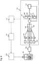
- the system for cultivating cells of the present invention is constituted by a bioreactor/fermentor 1, a plurality of feed medium vessels 2, an aseptic sampling device 3, an analyzer 4, an analysis device 5, and a control device 6.
- the system for cultivating cells of the present invention preferably samples the culture solution aseptically from the bioreactor/fermentor 1 and measures the component in the culture solution, etc. Based on the measurement results, the state of a cell at the time of the measurement is analyzed.
- control device 6 selects the optimal feed medium based on the state of the cell, determines an amount to be fed, and controls the selection of the feed medium to be added from a plurality of feed medium vessels 2 by activating a valve 7 and a pump 8.
- the selection of the feed medium in accordance with the state of a cell can significantly enhance the productivity of an intended substance, etc., produced by the cell.
- Examples of the plurality of feed media to be loaded in a plurality of the feed medium vessels 2 herein include those designed to have different compositions of a carbon source and/or a nitrogen source among the feed media used for the typical fed-batch culture.
- Examples of the carbon source include glucose, sucrose, etc.
- examples of the nitrogen source include amino acids such as glutamic acid, etc.
- An example is the plurality of feed media designed so that a carbon source concentration is constant and a nitrogen source concentration changes in steps.
- another example is the plurality of feed media designed so that a nitrogen source concentration is constant and a carbon source concentration changes in steps.
- another example is the plurality of feed media designed so that a carbon source concentration and a nitrogen source concentration respectively change in steps.
- the IFN-gamma producing CHO cell increases the production of antibody when cultivated under maintained constant concentration by independently controlling a glutamine concentration and a glucose concentration ( Chee Fumg Wong D, et al., Biotechnol Bioeng. 2005, Jan. 20; 89(2): 164-177 .). Further, it is known that when a glutamine concentration in the culture solution or the ratio of a glutamine concentration to a glucose concentration changes, the glycosylation pattern which affects the antibody activity changes.
- the glycosylation pattern changes between when IFN-gamma producing CHO cell is cultivated at a glutamine concentration maintained at 0.1 mM, 0.3 mM and 0.5 mM, respectively, and when cultivated at a glutamine concentration maintained at 0.3 mM and a glucose concentration maintained at 0.35 mM and 0.7 mM, respectively. Accordingly, produced antibodies may not have uniform quality from lot to lot due to the nutritional imbalance in the culture solution. To solve this problem, it is preferable to control the concentrations of glutamine and glucose, respectively, within the range of ⁇ 0.1 mM and ⁇ 0.18 mM.
- a metabolic flux analysis which analyzes the metabolism in a cell is used. Since the technique of the conventional intracellular metabolic flux analysis requires to regulate a state of cells until an intracellular metabolic state is reflected to the labeled information on an amino acid, time-dependent changes in an intracellular metabolic flux distribution could not be evaluated. Under this circumstance, time-dependent changes in an intracellular metabolic flux distribution can be measured from either one of the experiments of the following two methods.
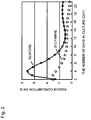
- FIG. 3 shows the relationship between the consumption rate and specific growth rate of glucose and glutamine.
- the state can be classified into three states as shown in the figure.
- the cell state is classified by measuring the growth rate during culture, thereby feeding a feed medium suitable for each state.
- the present invention shows that the culture state can be classified using the specific growth rate as an indicator, but the classification can be made using other indicators.
- a metabolic rate of amino acid, etc., at each state of culture cells can be determined.
- the thus determined metabolic rate is the bare minimum consumption required for cells to sustain the life and grow, and a nutrient amount exceeding that consumption invites an unnecessary increase of a secretion.
- the optimal nutritional environment for cell growth can be achieved by considering such a metabolic rate as a consumption to be consumed by cells.
- a feed medium composition ratio is determined based on a metabolic flux distribution (an averaged value of the entire culture processes) also in the conventional method ( Xie L and Wang DI 1994, Cytotechnology 15(1-3): 17-29 ).
- a metabolic rate of each amino acid, etc., at each culture state is determined by employing the same technique to a metabolic flux distribution of each culture state (each culture time) and a feed medium suitable for each state of culture cells can be designed by making feed medium components as a ratio of each nutrition metabolic rate.
- the medium design of the present invention can be designed with 10% error.
- the culture is often carried out by regulating the concentrations of glutamine and glucose at 0.3 mM and 0.4 mM, with the limits of error being 0.03 mM and 0.04 mM, respectively. Consequently, it is possible to regulate the to-be-attained concentrations of glutamine and glucose at ⁇ 0.1 mM and ⁇ 0.18 mM, respectively.
- the regulation may be achieved by independently designing glucose and glutamine to effectively inhibit ammonia and lactic acid secretions, and feeding them independently in accordance with a culture state.
- the culture is performed while maintaining nutrient concentrations such as amino acids, etc., low to inhibit the ammonia accumulation.
- apoptosis resistance The tolerance against apoptosis from the nutritional deficiency (apoptosis resistance) varies even among allogeneic cells, and it is reported that such a resistance depends on mitochondrion membrane potential in a cell. Apoptosis by undernutrition is first induced in cells with a low apoptosis resistance, and then spreads to those with a higher apoptosis resistance. Under such a circumstance, a control is achieved wherein apoptosis is monitored during the culture steps and the controlled value of nutrient concentration is set to a higher value at the time of detecting apoptosis.
- examples of the indication to be monitored include viable cell count and apoptosis cell count.
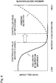
- a method can be used wherein a viable cell count is estimated by measuring an amount of glucose and an amount of lactic acid in a culture solution. As shown in FIG. 5 , the sum of glucose consumption and lactic acid consumption is in the linear relationship with the time integral value of the viable cell count. With this relational expression being measured beforehand as a calibration curve, a viable cell count during the culture steps can be estimated by determining the sum of glucose consumption and lactic acid consumption by the measurement. The comparison between the viable cell count estimated by this method and the viable cell count estimated by the conventional trypan blue staining is as shown in FIG. 6 which shows both counts are well synchronized. From this result, a viable cell count can be measured by this method.
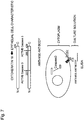
- cytokeratin 18 protein expressed in a cell is cleaved by caspase 3 resulting from apoptosis and secretes fragments (M30 fragment) having a M30 recognition site
- a method can be employed wherein the fragment secreted in the culture solution can be detected by ELISA using the M30 antibody ( FIG. 7 ). Shown below is an example in which apoptosis was measured by the ELISA method using a 96-well plate.
- the ELISA method using the M30 antibody is first described.
- Anti-cytokeratin 18 antibody (M5 antibody; Roche Diagnostics) was bonded to a 96-well plate. Blocking was then carried out using skim milk, a culture solution was fed thereto, and an incubation was conducted at 37°C for an hour. After washing three times, a biotin-labeled M30 antibody solution (Roche Diagnostics) was added thereto, and an incubation was conducted at 37°C for an hour. After washing three times, an HRP-labeled Streptavidin solution was added thereto, and an incubation was conducted at 37°C for an hour. After washing three times, a TMB substrate solution was added thereto, an incubation was performed at room temperature for 20 minutes, and subsequently sulfuric acid was added, thereby measuring an absorbance at 450 nm.
- apoptosis was measured using a culture solution in which a CRL-1606 cell was fed-batch cultivated in a 1-L bioreactor/fermentor.
- the culture with stirring was carried out under the culture conditions of 37°C and a 60% saturated dissolved oxygen concentration.
- 5 mL of the culture solution aseptically containing cells was sampled every 12 hours, and 1 mL of this solution was subjected to measurement of the total cell count and viable cell count, using a ViCell viable cell counter (Beckman Coulter).
- the cells in the remaining culture solution were settled using a centrifuge (800 rpm, 5 minutes), and the supernatant was cryopreserved. After completing the culture, the M30 fragment was detected in the same manner as above.
- FIG. 8 is a graph showing the time-dependent changes in the M30 fragment in the culture solution in the 1 L bioreactor/fermentor and the time-dependent changes in the total cell count and viable cell count. As the viable cell count decreases, i.e., as the dead cell count increases, the amount of M30 fragment is found increased. It is verified that the method for detecting apoptosis of the present invention enables the detection of apoptosis from the culture solution.
- the viable cell count and apoptosis can be measured from the culture solution by the method described above, but apoptosis may also be measured using a microreaction field for even quicker measurement with higher sensitivity.
- a system for cultivating cells equipped with a microreaction field has the structure shown in FIG. 9 .
- the system for cultivating cells is provided with a bioreactor/fermentor 101, a filter 102 for separating cells contained in the culture solution in the bioreactor/fermentor 101, an apoptosis detector 113 for detecting the M30 fragment contained in the culture solution free of the cells via the filter 102, a recorder 114 for recording measured values resulting from the M30 fragment detected by the apoptosis detector 113, an analysis device 115 for analyzing the apoptosis based on the measured values recorded by the recorder 114, and a control device 116 for selecting a feed medium to be added to the bioreactor/fermentor 101 out of a plurality of feed-medium vessels (not shown) based on the results analyzed by the analysis device 115.
- the apoptosis detector 113 is provided with pumps 103 for fluxing a reagent required for each component analysis to be described later, syringes 104 for containing the reagents, a microchannel 105 for detecting the M30 fragment, a chip 106 on which the microchannel 105 is formed, an absorption spectrometer 107, and a waste fluid tank 112. Furthermore, the absorption spectrometer 107 consists of a detector 108, a cell 109, and a wavelength filter 110 arranged on the optical axis from a light source 111.
- a primary antibody (anti-cytokeratin 18 antibody; M5 antibody) is allowed to bond in the microchannel 105.
- the culture solution passed through the filter 102 to prevent the cells from contaminating from the bioreactor/fermentor 101, is allowed to flow into the apoptosis detector 113 using a pump not shown. If the cell death is apoptosis, the M30 fragment is present in the culture solution and binds to the above primary antibody.
- the biotin-bonded M30 antibody is then fluxed using a microsyringe. After fluxing a wash solution, streptavidin conjugated with alkaline phosphatase is allowed to flow.
- NBT nitro-blue tetrazolium chloride
- an absorbance was measured at 405 nm using the absorption spectrometer 107, thereby measuring the presence or absence and an amount of apoptosis.
- the proteins excluding the primary antibody can be washed out by flowing an acidic solution or alkaline solution through the channel.
- Another apoptosis measurement can be carried out using the same chip 106 by fluxing a wash solution and delivering a blocking solution.
- the measured results are recorded by the recorder 114 and analyzed by the analysis device 115 to attain optimal control, and a not shown plurality of feed-medium vessels are controlled by the control device 116, whereby culture can be performed under the optimal environment for cells and the productivity is hence enhanced. Further, the data stored in the recorder 114 can be used as one of the quality control indicators.
- streptavidin conjugated with alkaline phosphatase was used in the above, but streptavidin conjugated with horseradish peroxidase may also be used.
- TMB 3,3',5,5'-tetramethylbenzidine
- sulfuric acid is mixed therein and an absorbance at 450 nm is measured.
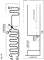
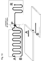
- a microreaction field consists of, for example, an antibody reaction unit as indicated between A and Q, a sulfuric acid flow channel as indicated between B and P, and a mixing channel for mixing the sulfuric acid and the reacted TMB as indicated between P and R, as shown in FIG. 10 .
- the flow After loading the unit between A and Q with TMB for an antibody reaction, the flow is withheld to secure a sufficient reaction time. After the adequate reaction, the flow is resumed and mixed with sulfuric acid. At the time of resuming the flow, sulfuric acid may flow into the reaction field from the sulfuric acid flow channel (including the inflow by the diffusion). Thus, if the mixing channel becomes an acidic condition, the physical bonds between proteins are cleaved whereby the precise measurement may not be achieved. To improve the possible problem, the channel structure should be either one of the following structures.
- the above structures (1) to (4) enable the prevention of sulfuric acid from flowing (including the inflow by the diffusion) into the microchannel for the reaction.
- the chip 106 to which the primary antibody is bound has an amino group treated on the channel inner wall.
- a glutaraldehyde solution is allowed to flow through the channel to activate the amino group, the channel is washed with pure water, and M5 antibody is delivered to be covalently bound to the channel inner wall.
- the blocking solution is fluxed to close the channel opening to prevent it from drying, thereby making it possible to store at 4°C. Since the chip, once mounted to the apoptosis detector before the operation of the bioreactor/fermentor, can be reused, it does not need to be replaced until the operation is completed.
- the method for covalently binding the antibody to the chip channel may be performed using a carboxyl group.
- the binding using the covalent bond is a desirable method when the chip is reused, but the binding using the hydrophobic bond may be employable when the chip does not need to be reused.
- FIG. 14 shows the relationship between the glucose concentration and chromogenic intensity. In the method, the figure shows a linear relationship up to a glucose concentration of 600 mg/1.
- FIG. 15 shows the relationship between the lactic acid concentration and chromogenic intensity. In the method, the figure shows a linear relationship up to a lactic acid concentration of 135 mg/1.
- FIG. 16 shows the relationship between apoptosis and chromogenic intensity. The measurement can be carried out with higher sensitivity when a microreaction field is used than when a 96-well plate is used.
- a colorimetric assay was employed wherein the hydrogen peroxide, produced when glucose is oxidized by an enzymatic reaction with glucose oxidase, was caused to be produced, and the hydrogen peroxide, p-hydroxybenzoic acid amino and amino antipyrine were caused to form a red quinone imine compound by an enzymatic reaction with peroxidase.
- the mixing ratio of the chromogenic reagent and sample solution in the solution flux mixing reaction using the microchip was 9:1.
- a chromogenic reagent and a reagent were instilled at 90 ⁇ l/min and 10 ⁇ l/min, respectively, using a syringe pump and mixed in the chip, and an absorbance at a wavelength of 510 nm was measured using a spectrophotometer.
- the absorbance by the chromogenic reaction was determined by the variation between the thus obtained absorbance and the chromogenic solution absorbance that had been measured separately beforehand.
- a colorimetric assay was employed wherein the hydrogen peroxide, produced when lactic acid is oxidized by an enzymatic reaction, was used.
- the mixing ratio of the chromogenic reagent and sample solution in the solution flux mixing reaction using the microchip was 9:1.
- a chromogenic reagent and a reagent were instilled at 90 ⁇ l/min and 10 ⁇ l/min, respectively, using a syringe pump and mixed in the chip, and an absorbance at a wavelength of 510 nm was measured using a spectrophotometer.
- the absorbance by the chromogenic reaction was determined by the variation between the thus obtained absorbance and the chromogenic solution absorbance that had been measured separately beforehand.
- an aseptic sampling of the culture solution from which the cell has been removed is desirable.
- an aseptic sampling apparatus of the culture solution for performing such an aseptic sampling is desirable.
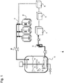
- FIG. 17 is a flow diagram showing the operation of an embodiment of the aseptic sampling apparatus of the present invention.
- the sampling apparatus is provided with a rotating filter 201 equipped with a filter 202 on the circumferential surface for blocking the cell from passing therethrough, a filter container 204 for containing the rotating filter 201, a filter drive motor 205 for rotating the filter, a pressure gauge 206 for detecting the inner pressure of the rotating filter 201, a pressure gauge 207 for detecting the pressure of the filter container, a backwash water reservoir 208, a pressure gauge 209 for detecting the inner pressure of the backwash water reservoir 208, and a pressure control valve 210 for adjusting the pressure inside the backwash water reservoir 208.
- the filter container 204 is provided with culture solution circulation channels 220 and 221 between the bioreactor/fermentor and itself for circulating the culture solution using a solution flow device such as a pump, etc.
- the bioreactor/fermentor and solution flow device are not shown in FIG. 17 . Owing to this structure, the culture solution inside the filter container 204 is constantly replaced, thereby inhibiting the adverse affects to the culture resulted from the deteriorated environment caused by the partial high density of the cell due to draining of a filtrate by filtering and a prolonged retention time.
- the filter container 204 It is essential for the filter container 204 to have the function for preventing the culture solution inside from outflowing therefrom and blocking outside contaminants from entering the container.
- the filter container 204 is provided with an axial seal 215 using mechanical seals.
- the mechanical seals serve to stop the leaks of gas and liquid by allowing a sliding member fixed to a rotation axis 213 to rotate and the other sliding member fixed to the axial seal 215 to tightly contact and slide together.
- the present embodiment uses two mechanical seals, i.e., a mechanical seal 216a for preventing the culture solution inside the filter container 204 from outflowing therefrom and the other mechanical seal 216b for blocking outside contaminants from entering the container.
- a seal chamber 217 is provided between the mechanical seals 216a and 216b to serve as a channel connecting the inside and outside the rotating filter 201.
- the mechanical seal is not limited, and can be any mechanical seals and dry mechanical seals used for the typical culture apparatus insofar as they are capable of maintaining airtightness. Further, the method for using and arrangement of the mechanical seals are not limited to those described in the present embodiment.
- the rotation axis 213 has a hollow structure with both ends sealed, and forms an axial channel 214 by opening one end to the seal chamber 217 and opening the other end so that it communicates with a filtrate channel 212 provided in a cylinder 203 to be described later.
- the axial seal 215 is provided with a communication nozzle 218 at the position of the seal chamber 217, and used for taking in and out of a filtrate and backwash solution.
- the rotating filter 201 has a structure wherein the cylinder 203 and filter 202 are mounted to the rotation axis 213 and the upper and bottom ends thereof are sealed with sealing members, wherein the filtration is carried out by lowering the pressure inside the filter than that of the outside, thereby obtaining the filtrate that has passed through pores of the filter.
- rotating the rotating filter 201 inside the filter container 204 causes parallel streams of the culture solution on the surface of filter 202, resulting in a so-called crossflow filtration state.
- the gap between the inner wall of the filter container 204 and the surface of the filter 202 is made small to create a turbulent flow state, the highly densified layer of cells and microscopic particles formed by draining the filtrate can be diffused.
- the rotation speed of the rotating filter is determined based on the resistance of an animal cell to be cultivated against physical external forces and the configuration of a separation device.
- the filtrate passed through the filter 202 flows through a cylindrical gap 211 formed between the cylinder 203 and the filter 202, leads to the seal chamber 217 in the axial seal 215 via the axial channel 214 provided in the rotation axis 213 and the filtrate channel 212 provided in the cylinder 203, and is transferred to the backwash water reservoir 208 by way of valves 240 and 241 along the communication channel connected to the communication nozzle 218.
- the filter used in the present system for cultivating cells is not limited as long as it can block the cell passage such as clothes, membrane filters, and like those typically used.
- a filter having mechanical strengths, heat resistance and corrosion resistance to endure a washing solution injection when a steam is blown into the rotating filter for the sterilization and washing.
- a filter having filtering properties which prevents healthy cells from passing therethrough and allows small cell fragments to pass therethrough.
- the present embodiment used a metal filter on which a slit opening was formed by cylindrically winding a stainless thread at given intervals.
- the present filter prevents the only cells larger than the slit width from passing therethrough and allows the microparticles such as cell fragments, etc., smaller than the slit width to pass therethrough.
- the slit width is determined in accordance with the size of cell to be cultivated, and typically ranges from 5 to 30 ⁇ m.
- the backwash water reservoir 208 is provided with a liquid level indicator 219 housed therein for measuring a liquid level, a pressure gauge 209 for detecting an internal pressure, and a pressure control valve 210 for adjusting the inner pressure of the backwash water reservoir.
- the backwash water reservoir 208 is connected to the communication nozzle 218 by opening the valves 241 and 244, a tank 234 in the analyzer by opening valves 241 and 244, and the bioreactor/fermentor by opening a valve 242, respectively, thereby enabling the solution to travel.
- the tank 234 in the analyzer and the bioreactor/fermentor are not shown in FIG. 17 .
- the pressure adjustment inside the backwash water reservoir 208 is carried out by adjusting an air amount blown thereinto by opening and closing the valve 243 and adjusting a degassing amount by opening and closing the pressure control valve 210.
- the inner pressure of the backwash water reservoir 208 is constantly maintained higher than atmospheric pressure in the present invention.
- the air used for adjusting the pressure is aseptic air from which bacteria and like microparticles have been already removed.
- the liquid level indicator 219 is not limited, but it is preferable to select those having mechanical strengths, heat resistance and corrosion resistance to endure a washing solution injection when a steam is blown into the rotating filter for the sterilization and washing. Further, since numerous cells and small cell fragments resulted from the cytolysis of dead cells are present in the culture solution and bubbles are likely to stay on the liquid surface, it is preferable to select those less likely to cause malfunctions due to the dirty sensor.
- the electrostatic capacity level sensor was used in the present embodiment.
- the culture solution is allowed to circulate in the filter container 204, and the rotating filter 201 is rotated using the filter drive motor 205.
- the pressure of the filter container was measured using the pressure gauge 207, and the pressure of inside the backwash water reservoir 208 was measured using the pressure gauge 209.
- the pressure of the filter container is the same as that of the bioreactor/fermentor, and is typically pressurized to 0.01 to 0.05 MPa.
- the pressure inside the backwash water reservoir 208 is adjusted using the pressure control valve 210 so that it is slightly lower than the pressure of the filter container. Consequently, the valves 241 and 240 are opened one by one, the filtration is performed in the filter 202 and the filtrate flows into the backwash water reservoir 208.
- the liquid level of the filtrate is measured using the liquid level indicator 219, and the valves 240 and 241 are closed one by one at the time of the level reaching a determined level, whereby the filtration step is completed. It is not preferable to carry out the filtration operation rapidly by applying high filtration differential pressure because it facilitates the clogging.
- the differential pressure of the filter container 204 and the backwash water reservoir 208 i.e., the filtration differential pressure
- the adjustment of the filtration rate is performed by adjusting the filtration differential pressure of the filter container 204 and the backwash water reservoir 208.
- the open time duration is adjusted by continuously opening and closing the valve 240 to attain a desired pressure.
- the inner pressure of the backwash water reservoir 208 is set higher than that of the tank 234 provided in the analyzer by opening the valve 243. Subsequently, the filtrate is delivered to the tank 234 in the analyzer by opening the valves 241 and 244 one by one. The liquid level of the filtrate is measured using the liquid level indicator 219, and the valves 244 and 241 are closed one by one at the time of the level reaching a determined level, whereby the filtrate discharge step is completed. For setting the pressure, it is necessary to consider the liquid levels of the tank 234 in the analyzer and the backwash water reservoir 208.
- the pressure when the liquid level of the tank 234 in the analyzer is higher than that of the backwash water reservoir 208, the pressure must be set high not to cause a back flow.
- the liquid level of the tank 234 in the analyzer is lower than that of the backwash water reservoir 208, air is injected so as not for the inner pressure of the backwash water reservoir 208 to become lower than atmospheric pressure due to the filtrate outflow.
- the inner pressure of the backwash water reservoir 208 is adjusted to be lower than that of the bioreactor/fermentor using the pressure control valve 210. Subsequently, the medium flows into the backwash water reservoir 208 by opening the valve 242. The liquid level of the medium is measured using the liquid level indicator 219, and the valve 242 is closed at the time of the level reaching a determined level, whereby the medium supply is completed.
- the pressure it is necessary to consider the liquid levels of the bioreactor/fermentor and the backwash water reservoir 208. More specifically, when the liquid level of the bioreactor/fermentor is higher than that of the backwash water reservoir 208, the differential pressure must be set low so as not for the delivery rate of the medium to be high.
- the differential pressure When the liquid level of the bioreactor/fermentor is lower than that of the backwash water reservoir 208, the differential pressure must be set high so that the medium is delivered. When the delivery rate of the medium needs to be adjusted, the open time duration is adjusted by intermittently opening and closing the valve 242 for the desired adjustment.
- the inner pressure of the backwash water reservoir 208 is set higher than that of the filter container 204 by opening the valve 243.
- the number of rotations of the rotating filter 201 is increased greater than that in the filtration step.
- a medium is injected to the rotating filter 201 by opening valves 241 and 240 one by one, allowed to pass through the pores of the filter 202 backward from the direction in the filtration step, flows into the filter container 204, and is supplied to the bioreactor/fermentor by way of the culture solution circulation channel 221. More specifically, the medium, when supplied to the bioreactor/fermentor, serves as a backwash solution of the filter 202.
- the liquid level of the medium is measured using the liquid level indicator 219.
- the inner pressure of the backwash water reservoir 208 is adjusted, using a pressure control valve 210, to be higher than the inner pressure of the filter container 204 and lower than the pressure combining the inner pressure of the filter container 204 and the bubble point pressure of the filter 202.
- the valves 244 and 241 are closed one by one, and the number of rotations of the rotating filter 201 is decreased to the same as in the filtration step, thereby completing the backwash step.
- the backwash carried out in the rotating filter 201 spun at a high speed, enables the backwash solution to spread uniformly throughout the entire inner surface of the filter 202. Further, the cleaning effect additionally provided by the centrifugal force generated from the rotation imparts even greater backwash effects.
- the inner pressure of the backwash water reservoir 208 is adjusted to be higher than the inner pressure of the filter container 204 and lower than the pressure combining the inner pressure of the filter container 204 and the bubble point pressure of the filter 202, the medium in the cylindrical gap 211, filtrate channel 212, axial channel 214 and communication channel can be all discharged to the filter container 204. In other words, the expensive medium can be entirely subjected to the culture with no waste.
- the bubble point pressure of the filter is determined by sinking the rotating filter 201 in the medium, injecting an air therein, and measuring the pressure at the time of bubbles first being released from the filter surface.
- the separation operation of animal cells can be continued by repeating the above operations (1) to (4).
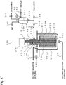
- FIG. 18 is a flow diagram depicting the operation of an example of the system for cultivating cells according to an embodiment of the present invention.
- the present system for cultivating cells consists of a bioreactor/fermentor 231, a cell separation device 232, medium vessels 233 storing a feed medium and a tank 234 in the analyzer.
- the system for cultivating cells is provided with a plurality of medium vessels 233, but it is not shown in FIG. 18 .
- the cell separation device 232 the separation device of the animal cell of the present invention shown in FIG. 17 is used.
- the system for cultivating cells is provided with, but not shown in FIG. 18 , a system for supplying gas such as air, oxygen, nitrogen, carbon dioxide, etc., a hot/cold water supply system, a steam supply system and a plumbing system, which are all essential.
- the bioreactor/fermentor 231 is shown in a cross sectional view.
- the culture solution 222 placed in the bioreactor/fermentor 231 is stirred by a mixer 236 powered by a drive motor 235 and mixed homogeneously.
- Oxygen required for the culture is supplied by two methods; the in-solution gas-flow technique wherein an oxygen-containing gas is supplied into the solution from the air diffuser 237 disposed on the bottom of the bioreactor/fermentor, and the upper surface gas-flow technique wherein the gas is aerated into the gaseous phase portion at the upper part of the bioreactor/fermentor 231.
- the bioreactor/fermentor 231 is provided with a measuring device 238 for measuring characteristics of the culture solution 222 and obtains the measured values 239 of dissolved oxygen concentration, dissolved carbon dioxide concentration, pH, temperature, ammonia concentration, lactic acid concentration, glucose concentration, glutamine concentration and caspase or caspase digest concentration.
- the measuring device 2308 the actual system is provided with a detection device at each item to be detected or controlled, but FIG. 18 shows only one device for simplicity.
- the measured values 239 are input into the not shown control device and used as the information for selecting a feed medium from a plurality of medium vessels 233 as described earlier.
- the gas-flow systems to the solution and the upper surface are provided with individual operation devices 250a and 250b, respectively, for regulating the gas supplies. Further, the individual operation devices 250a and 250b are each provided with a flow rate control function and a supply measurement function for each of air, oxygen and carbon dioxide.
- the individual operation device 250a which controls the gas supply regulates the gas composition and gas flow rate.
- air was flowed at a constant rate, and carbon dioxide was mixed in accordance with pH of the culture solution. The regulation of a carbon dioxide concentration was carried out, using pH as controlled variable, by the typical proportional control wherein the carbon dioxide flow rate is the operation factor.
- the individual operation device 250b which controls the gas supply regulates the gas composition and gas flow rate.
- the dissolved oxygen concentration of the culture solution is a controlled variable
- the oxygen flow rate is the operation factor.
- the bioreactor/fermentor 231 has a constant pressure maintained by the pressure control valve 252, based on the measurement results by the pressure gauge 251.
- the pressure is typically applied to 0.01 to 0.05 MPa to prevent bacteria, etc., from entering the bioreactor/fermentor from outside.
- Culture solution circulation channels 220 and 221 are provided between the cell separation device 232 and, the bioreactor/fermentor 231 to circulate the culture solution 222 using the pump 248.
- the culture solution circulation channels 220 and 221 are provided with valves 245, 246 and 247 which are opened and closed as necessary at the time of stopping the culture solution circulation, draining the culture solution from the cell separation device 232, etc.
- Communication channels 253 and the valve 254 for communicating each gaseous phase are provided between the bioreactor/fermentor 231 and backwash water reservoir 208.
- the inner pressures of the bioreactor/fermentor 231 and backwash water reservoir 208 can be easily synchronized by opening the valve 254. It is particularly advantageous to adjust the inner pressure of the backwash water reservoir 208 to be slightly lower than that of the bioreactor/fermentor 231 at the initiation of the filtration step.
- the medium vessel 233 is a tank for storing a feed medium to be supplied to the bioreactor/fermentor 231 and provided with a mixer 255, a mixer drive motor 256, a pressure gauge 257 for detecting an inner pressure, a pressure control valve 258, and an air supply valve 259.
- the medium vessel 233 is connected to the backwash water reservoir 208 by way of the valves 242, 260 and communication channels, enabling the delivery of a feed medium to the backwash water reservoir 208.
- the medium vessel 233 is maintained at a constant pressure by the pressure control valve 258, based on the measured results of the pressure gauge 257.
- the pressure is typically applied to 0.01 to 0.05 MPa to prevent bacteria, etc., from entering from outside thereinto. Further, the medium vessel 233 is cooled to 5 to 10°C to prevent the stored medium from being deteriorated.
- the tank 234 in the analyzer is a tank for storing the filtrate wherein a target material to be produced separated in the cell separation device 232 is dissolved, and provided with a mixer 261, a mixer drive motor 262, a pressure gauge 263 for detecting an inner pressure, a pressure control valves 264 and an air supply valve 265.
- the tank 234 in the analyzer is connected to the backwash water reservoir 208 by way of the valves 241 and 244 and the communication channel, enabling the reception of the filtrate from the backwash water reservoir 208.
- the tank 234 in the analyzer is maintained at a constant pressure by the pressure control valve 264, based on the measured results by the pressure gauge 263.
- the pressure is typically applied to 0.01 to 0.05 MPa to prevent bacteria, etc., from entering the tank from outside. Further, the tank 234 is cooled to 5 to 10°C to prevent the target substance from being deteriorated while stored.
- the continuous culture using the system for cultivating cells of the present invention is carried out by repeating the four steps of the animal cell separation technique described earlier, i.e., (1) filtration step, (2) filtrate discharge step, (3) medium delivery step, and (4) backwash step.
- a plurality of selectable media each having a different composition and stored in a plurality of medium vessels 233 can be selected based on a state of a cell and supplied to the bioreactor/fermentor 231, whereby the intended product with high quality can be produced with a high yield.
Landscapes
- Life Sciences & Earth Sciences (AREA)
- Health & Medical Sciences (AREA)
- Chemical & Material Sciences (AREA)
- Wood Science & Technology (AREA)
- Organic Chemistry (AREA)
- Engineering & Computer Science (AREA)
- Bioinformatics & Cheminformatics (AREA)
- Zoology (AREA)
- Biomedical Technology (AREA)
- Sustainable Development (AREA)
- Microbiology (AREA)
- Biotechnology (AREA)
- Biochemistry (AREA)
- General Engineering & Computer Science (AREA)
- General Health & Medical Sciences (AREA)
- Genetics & Genomics (AREA)
- Molecular Biology (AREA)
- Analytical Chemistry (AREA)
- Cell Biology (AREA)
- Apparatus Associated With Microorganisms And Enzymes (AREA)
- Micro-Organisms Or Cultivation Processes Thereof (AREA)
Claims (4)
- System zum Kultivieren von Zellen, umfassend:einen Bioreaktor / Fermenter (1) zum Kultivieren von zu kultivierenden Zellen;eine Messvorrichtung (4, 5) zum Messen der Kulturzellen, die in dem Bioreaktor / Fermenter (1) kultiviert werden, oder eines Bestandteils, der in der Kulturlösung enthalten ist; undeine Steuerungsvorrichtung (6, 7) zum Auswählen eines dem Bioreaktor / Fermenter zuzuführenden Zufuhrmediums aus zwei oder mehr Zufuhrmedien mit unterschiedlichen Zusammensetzungsverhältnissen abhängig von einem Zustand der Kulturzellen,welcher durch einen von der Messvorrichtung (4, 5) gewonnenen Messwert bestimmt ist,dadurch gekennzeichnet, dassdie Messvorrichtung (4, 5) dazu ausgelegt ist, mittels einer intrazellulären metabolischen Flussanalyse eine metabolische Flussverteilung zu messen, unddie Steuervorrichtung (6, 7) dazu ausgelegt ist, die Bestandteile der Zufuhrmedien in einem Verhältnis der jeweiligen metabolischen Rate zu bestimmen, die durch die metabolische Flussverteilung in einem von der Messvorrichtung (4, 5) ermittelten unstetigen Zustand bestimmt ist.
- Verfahren zum Kultivieren von Zellen, umfassend die Schritte:Kultivieren von Zellen in einer Kulturlösung;Messen der kultivierten Zellen oder eines in der Kulturlösung enthaltenen Bestandteils; undAuswählen eines Zufuhrmediums aus zwei oder mehr Zufuhrmedien mit unterschiedlichen Zusammensetzungsverhältnissen abhängig von einem Zustand der Kulturzellen, der durch einen im Messschritt erhaltenen Messwert ermittelt wird, und Zugabe des Zufuhrmediums zu der Kulturlösung,gekennzeichnet durchdas Messen einer metabolischen Flussverteilung mittels einer intrazellulären metabolischen Flussanalyse, undda Auswählen der Bestandteile der Zufuhrmedien in einem Verhältnis der jeweiligen metabolischen Rate, die durch die metabolische Flussverteilung in einem unstetigen Zustand bestimmt ist.
- System nach Anspruch 1, wobei die intrazelluläre metabolische Flussanalyse ein Analyseverfahren ist, welches die Elementare Metabolit-Einheit (EMU) nutzt oder wobei die zwei oder mehr Zufuhrmedien unterschiedliche Zusammensetzungsverhältnisse einer Kohlenstoffquelle und einer Stickstoffquelle haben.
- Verfahren nach Anspruch 2, wobei die zwei oder mehr Zufuhrmedien unterschiedliche Zusammensetzungsverhältnisse einer Kohlenstoffquelle und einer Stickstoffquelle haben oder wobei die intrazelluläre metabolische Flussanalyse ein Analyseverfahren ist, welches die Elementare Metabolit-Einheit (EMU) nutzt.
Applications Claiming Priority (1)
| Application Number | Priority Date | Filing Date | Title |
|---|---|---|---|
| JP2008251406A JP4883067B2 (ja) | 2008-09-29 | 2008-09-29 | 培養装置及び培養方法 |
Publications (3)
| Publication Number | Publication Date |
|---|---|
| EP2169048A2 EP2169048A2 (de) | 2010-03-31 |
| EP2169048A3 EP2169048A3 (de) | 2010-12-08 |
| EP2169048B1 true EP2169048B1 (de) | 2018-03-21 |
Family
ID=41559680
Family Applications (1)
| Application Number | Title | Priority Date | Filing Date |
|---|---|---|---|
| EP09010406.8A Revoked EP2169048B1 (de) | 2008-09-29 | 2009-08-12 | System und Verfahren zur Kultivierung von Zellen |
Country Status (3)
| Country | Link |
|---|---|
| US (1) | US20100081122A1 (de) |
| EP (1) | EP2169048B1 (de) |
| JP (1) | JP4883067B2 (de) |
Cited By (1)
| Publication number | Priority date | Publication date | Assignee | Title |
|---|---|---|---|---|
| US11542564B2 (en) | 2020-02-20 | 2023-01-03 | Sartorius Stedim Data Analytics Ab | Computer-implemented method, computer program product and hybrid system for cell metabolism state observer |
Families Citing this family (40)
| Publication number | Priority date | Publication date | Assignee | Title |
|---|---|---|---|---|
| US8790913B2 (en) * | 2005-10-26 | 2014-07-29 | Pbs Biotech, Inc. | Methods of using pneumatic bioreactors |
| JP5872902B2 (ja) * | 2010-01-29 | 2016-03-01 | 中外製薬株式会社 | 新規な流加培養法 |
| US11512278B2 (en) | 2010-05-20 | 2022-11-29 | Pond Technologies Inc. | Biomass production |
| US8889400B2 (en) | 2010-05-20 | 2014-11-18 | Pond Biofuels Inc. | Diluting exhaust gas being supplied to bioreactor |
| US20120156669A1 (en) | 2010-05-20 | 2012-06-21 | Pond Biofuels Inc. | Biomass Production |
| US8969067B2 (en) | 2010-05-20 | 2015-03-03 | Pond Biofuels Inc. | Process for growing biomass by modulating supply of gas to reaction zone |
| US8940520B2 (en) | 2010-05-20 | 2015-01-27 | Pond Biofuels Inc. | Process for growing biomass by modulating inputs to reaction zone based on changes to exhaust supply |
| JP5710311B2 (ja) * | 2011-02-18 | 2015-04-30 | 株式会社日立製作所 | 添加培地の添加制御方法、及び当該方法を用いた細胞培養装置 |
| US20120276633A1 (en) | 2011-04-27 | 2012-11-01 | Pond Biofuels Inc. | Supplying treated exhaust gases for effecting growth of phototrophic biomass |
| DE102011082582B4 (de) * | 2011-09-13 | 2015-06-25 | Siemens Aktiengesellschaft | Verfahren zur Überwachung eines Fermentationsprozesses |
| JP2013085516A (ja) * | 2011-10-18 | 2013-05-13 | Hitachi Plant Technologies Ltd | 細胞培養制御方法、細胞培養制御装置及びこれを備える細胞培養装置 |
| JP6018808B2 (ja) * | 2012-06-12 | 2016-11-02 | 株式会社日立ハイテクノロジーズ | 微生物検査方法および検査システム |
| JP2014045663A (ja) * | 2012-08-29 | 2014-03-17 | Hitachi Ltd | 重層化及び/又は分化の程度を判定する方法並びに装置 |
| US9534261B2 (en) | 2012-10-24 | 2017-01-03 | Pond Biofuels Inc. | Recovering off-gas from photobioreactor |
| JP5913084B2 (ja) * | 2012-12-26 | 2016-04-27 | 株式会社日立製作所 | 培養制御方法、細胞培養装置及び細胞特性評価装置 |
| JP6135599B2 (ja) | 2014-05-19 | 2017-05-31 | 横河電機株式会社 | 細胞培養制御システム及び細胞培養制御方法 |
| EP3202911B1 (de) * | 2014-09-29 | 2023-09-20 | Tokyo Electron Limited | Verfahren zur bestimmung des undifferenzierten zustandes pluripotenter stammzellen durch kulturmediumanalyse |
| SG10201801943SA (en) | 2014-10-24 | 2018-05-30 | Genzyme Corp | Integrated continuous isolation of fluid streams from sterile process vessels |
| WO2016183032A1 (en) | 2015-05-08 | 2016-11-17 | Biomagnetic Solutions Llc | Apparatus and method for immunomagnetic cell separation |
| JP6113311B2 (ja) * | 2016-01-18 | 2017-04-12 | 株式会社日立製作所 | 培養制御方法、細胞培養装置及び細胞特性評価装置 |
| JP2017169518A (ja) * | 2016-03-25 | 2017-09-28 | 株式会社Ihi | 培養システム |
| JP6835347B2 (ja) * | 2016-08-24 | 2021-02-24 | 学校法人東京理科大学 | 代謝産物分析方法及び代謝産物分析装置 |
| JP6688754B2 (ja) * | 2017-03-24 | 2020-04-28 | 株式会社日立製作所 | 細胞培養装置の評価方法及び評価プログラム |
| JP7207643B2 (ja) * | 2017-06-21 | 2023-01-18 | 株式会社日立製作所 | 連続培養条件のスクリーニング方法 |
| CN111065724B (zh) | 2017-09-19 | 2023-02-21 | 株式会社Ihi | 培养装置 |
| JP7317466B2 (ja) | 2017-12-12 | 2023-07-31 | 株式会社日立製作所 | 細胞株及び培養条件のスクリーニング方法、及びその装置 |
| WO2019216887A1 (en) * | 2018-05-08 | 2019-11-14 | Biomagnetic Solutions Llc | A rigid chamber for cell separation from a flexible disposable bag |
| WO2019245078A1 (ko) * | 2018-06-20 | 2019-12-26 | 주식회사 디오스템스 | 줄기세포 증식기 |
| JP7231355B2 (ja) * | 2018-08-22 | 2023-03-01 | 日機装株式会社 | 細胞培養方法および細胞培養装置 |
| EP3859008B1 (de) * | 2018-11-02 | 2022-11-16 | PHC Holdings Corporation | Verfahren zur bestimmung der zellzahl und vorrichtung zur bestimmung der zellzahl |
| JP7075905B2 (ja) * | 2019-03-12 | 2022-05-26 | 株式会社日立製作所 | 模擬サンプル作成方法、模擬サンプル作成装置、数値モデル作成システム、及び数値モデル作成方法 |
| JP7257277B2 (ja) * | 2019-07-12 | 2023-04-13 | 株式会社日立製作所 | 細胞培養モニタリング装置及び細胞培養システム |
| JP7514912B2 (ja) * | 2019-08-02 | 2024-07-11 | テルモ株式会社 | 生体成分処理システム、生体成分処理装置及び細胞培養方法 |
| WO2021024880A1 (en) * | 2019-08-02 | 2021-02-11 | Terumo Kabushiki Kaisha | Biological component cassette, biological component kit, and biological component treatment system |
| CN112831528A (zh) * | 2020-12-30 | 2021-05-25 | 华东理工大学 | 一种基于在线电容值监测的葡萄糖补料发酵生产乙醇的方法 |
| WO2022186240A1 (ja) * | 2021-03-03 | 2022-09-09 | テルモ株式会社 | サンプリング方法 |
| JP7569709B2 (ja) * | 2021-03-03 | 2024-10-18 | テルモ株式会社 | サンプリング方法、及びサンプリング装置 |
| CN119497747A (zh) * | 2022-07-21 | 2025-02-21 | 昕芙旎雅有限公司 | 细胞培养装置及细胞数计算方法 |
| JPWO2024084779A1 (de) * | 2022-10-17 | 2024-04-25 | ||
| KR102834529B1 (ko) * | 2022-12-27 | 2025-07-17 | (주)진성유니텍 | 첨가물 투입 미세 조정이 가능한 신속 배양기 |
Citations (8)
| Publication number | Priority date | Publication date | Assignee | Title |
|---|---|---|---|---|
| JPS61293380A (ja) | 1985-06-20 | 1986-12-24 | Sanko Seisakusho:Kk | 微生物の培養方法及び培養装置 |
| EP0283726B1 (de) | 1987-03-23 | 1992-06-03 | Hitachi, Ltd. | Verfahren zur Züchtung durch Kontrollieren der Acetatkonzentration und Apparat dafür |
| WO1995013394A1 (en) | 1993-11-12 | 1995-05-18 | Cytokinetic, Inc. | Biochemical process for growing living cells by measuring the amount of nutrient added to the reaction medium |
| EP0661380A2 (de) | 1993-12-28 | 1995-07-05 | Ajinomoto Co., Inc. | Verfahren und Vorrichtung zum aeroben Kultivieren von Mikroorganismen |
| JP2005245440A (ja) | 2004-02-05 | 2005-09-15 | Ajinomoto Co Inc | 同位体で標識された基質を用いた細胞内代謝フラックスの解析方法 |
| US20060216818A1 (en) | 2005-03-24 | 2006-09-28 | Ken Amano | Control device for fermenter |
| JP2008178344A (ja) | 2007-01-24 | 2008-08-07 | Hitachi Plant Technologies Ltd | 細胞培養方法及び細胞培養装置 |
| US20080227136A1 (en) | 2006-09-13 | 2008-09-18 | Pla Itzcoatl A | Cell culture improvements |
Family Cites Families (6)
| Publication number | Priority date | Publication date | Assignee | Title |
|---|---|---|---|---|
| US4064015A (en) * | 1975-05-12 | 1977-12-20 | New Brunswick Scientific Co., Inc. | Control of biosynthesis in submerged culture |
| US4629686A (en) * | 1982-02-19 | 1986-12-16 | Endotronics, Inc. | Apparatus for delivering a controlled dosage of a chemical substance |
| GB8516415D0 (en) | 1985-06-28 | 1985-07-31 | Celltech Ltd | Culture of animal cells |
| JP3819847B2 (ja) * | 2003-01-09 | 2006-09-13 | 株式会社日立製作所 | 細胞培養による蛋白質生産プラントにおける蛋白質計測方法及びその装置 |
| JP2007202500A (ja) * | 2006-02-03 | 2007-08-16 | Hitachi Ltd | 培養槽の運転制御装置 |
| JP2007244341A (ja) | 2006-03-20 | 2007-09-27 | Hitachi Ltd | 生体細胞の培養制御方法及び培養制御装置 |
-
2008
- 2008-09-29 JP JP2008251406A patent/JP4883067B2/ja active Active
-
2009
- 2009-08-12 EP EP09010406.8A patent/EP2169048B1/de not_active Revoked
- 2009-08-18 US US12/543,015 patent/US20100081122A1/en not_active Abandoned
Patent Citations (8)
| Publication number | Priority date | Publication date | Assignee | Title |
|---|---|---|---|---|
| JPS61293380A (ja) | 1985-06-20 | 1986-12-24 | Sanko Seisakusho:Kk | 微生物の培養方法及び培養装置 |
| EP0283726B1 (de) | 1987-03-23 | 1992-06-03 | Hitachi, Ltd. | Verfahren zur Züchtung durch Kontrollieren der Acetatkonzentration und Apparat dafür |
| WO1995013394A1 (en) | 1993-11-12 | 1995-05-18 | Cytokinetic, Inc. | Biochemical process for growing living cells by measuring the amount of nutrient added to the reaction medium |
| EP0661380A2 (de) | 1993-12-28 | 1995-07-05 | Ajinomoto Co., Inc. | Verfahren und Vorrichtung zum aeroben Kultivieren von Mikroorganismen |
| JP2005245440A (ja) | 2004-02-05 | 2005-09-15 | Ajinomoto Co Inc | 同位体で標識された基質を用いた細胞内代謝フラックスの解析方法 |
| US20060216818A1 (en) | 2005-03-24 | 2006-09-28 | Ken Amano | Control device for fermenter |
| US20080227136A1 (en) | 2006-09-13 | 2008-09-18 | Pla Itzcoatl A | Cell culture improvements |
| JP2008178344A (ja) | 2007-01-24 | 2008-08-07 | Hitachi Plant Technologies Ltd | 細胞培養方法及び細胞培養装置 |
Non-Patent Citations (5)
| Title |
|---|
| ANTONIEWICZ, M. R. ET AL.: "Elementary metabolite units (EMU): A novel framework for modeling isotopic distributions", METABOLIC ENGINEERING, vol. 9, no. 1, 2007, pages 68 - 86, XP005733342 |
| ANTONIEWICZ, M. R. ET AL.: "Metabolic flux analysis in a nonstationary system: Fed-batch fermentation of a high yielding strain of E. coli producing 1,3-propanediol", METABOLIC ENGINEERING, vol. 9, no. 3, 2007, pages 277 - 292, XP022200680 |
| GOUDAR, C. ET AL.: "Towards industrial application of quasi real-time metabolic flux analysis for mammalian cell culture", ADVANCES IN BIOCHEMICAL ENGINEERING / BIOTECHNOLOGY, vol. 101, 2006, pages 99 - 118, XP009154520 |
| NADEAU, I. ET AL.: "Human 293 Cell Metabolism in Low Glutamine-Supplied Culture: Interpretation of Metabolic Changes through Metabolic Flux Analysis", METABOLIC ENGINEERING, vol. 2, no. 4, 2000, pages 277 - 292, XP055540750 |
| TEIXEIRA, A.P. ET AL.: "Hybrid elementary flux analysis/nonparametric modeling: application for bioprocess control", BMC BIOINFORMATICS, vol. 8, no. 30, 2007, XP021021812 |
Cited By (2)
| Publication number | Priority date | Publication date | Assignee | Title |
|---|---|---|---|---|
| US11542564B2 (en) | 2020-02-20 | 2023-01-03 | Sartorius Stedim Data Analytics Ab | Computer-implemented method, computer program product and hybrid system for cell metabolism state observer |
| US11795516B2 (en) | 2020-02-20 | 2023-10-24 | Sartorius Stedim Data Analytics Ab | Computer-implemented method, computer program product and hybrid system for cell metabolism state observer |
Also Published As
| Publication number | Publication date |
|---|---|
| EP2169048A2 (de) | 2010-03-31 |
| JP4883067B2 (ja) | 2012-02-22 |
| JP2010081809A (ja) | 2010-04-15 |
| EP2169048A3 (de) | 2010-12-08 |
| US20100081122A1 (en) | 2010-04-01 |
Similar Documents
| Publication | Publication Date | Title |
|---|---|---|
| EP2169048B1 (de) | System und Verfahren zur Kultivierung von Zellen | |
| Garn et al. | A flow injection analysis system for fermentation monitoring and control | |
| Zanzotto et al. | Membrane‐aerated microbioreactor for high‐throughput bioprocessing | |
| CN101796410B (zh) | 监测水中的微生物细菌的装置 | |
| US4939087A (en) | Method for continuous centrifugal bioprocessing | |
| JP3025015B2 (ja) | 流体媒体分析装置 | |
| AU2018286560B2 (en) | Control of carbon dioxide levels and ph in small volume reactors | |
| US6635441B2 (en) | Multi-sample fermentor and method of using same | |
| JP2023052399A (ja) | 微小液滴処理装置およびその使用方法 | |
| CN209485753U (zh) | 一种用于生物反应过程在线取样检测装置 | |
| US10745660B2 (en) | System for incubating microfluidic droplets and method for producing homogeneous incubation conditions in a droplet incubation unit | |
| Forman et al. | On-line monitoring and control of fermentation processes by flow-injection analysis | |
| Vaidyanathan et al. | Monitoring of submerged bioprocesses | |
| van der Pol et al. | Automation of selective assays for on-line bioprocess monitoring by flow-injection analysis | |
| Schügerl | Bioreaction engineering, bioprocess monitoring | |
| CN220850790U (zh) | 阀笼、往复运动活塞、调节阀和分析装置 | |
| US11060053B2 (en) | Method and device for hydrating a hydrating medium by a liquid sample | |
| Hilmer et al. | A new version of an in situ sampling system for bioprocess analysis | |
| Yoshida | Bioreactor development and process analytical technology | |
| WO2025050109A1 (en) | Completely noninvasive multi-analyte monitoring system for cell culture processes | |
| KR20250044764A (ko) | 바이오칩에서 dna/rna 생산을 측정하기 위한 장치 및 방법 | |
| EP4729626A1 (de) | Schnelles sterilitätstestverfahren und schnelle sterilitätstestplattform zur überprüfung der sicherheit von biopharmazeutika | |
| AU2008201519A1 (en) | Multi-sample fermentor and method of using same | |
| Van der Pol | On-line monitoring and control of animal-cell cultures | |
| AU2002242139A1 (en) | Multi-sample fermentor and method of using same |
Legal Events
| Date | Code | Title | Description |
|---|---|---|---|
| PUAI | Public reference made under article 153(3) epc to a published international application that has entered the european phase |
Free format text: ORIGINAL CODE: 0009012 |
|
| AK | Designated contracting states |
Kind code of ref document: A2 Designated state(s): AT BE BG CH CY CZ DE DK EE ES FI FR GB GR HR HU IE IS IT LI LT LU LV MC MK MT NL NO PL PT RO SE SI SK SM TR |
|
| AX | Request for extension of the european patent |
Extension state: AL BA RS |
|
| 17P | Request for examination filed |
Effective date: 20100331 |
|
| PUAL | Search report despatched |
Free format text: ORIGINAL CODE: 0009013 |
|
| AK | Designated contracting states |
Kind code of ref document: A3 Designated state(s): AT BE BG CH CY CZ DE DK EE ES FI FR GB GR HR HU IE IS IT LI LT LU LV MC MK MT NL NO PL PT RO SE SI SK SM TR |
|
| AX | Request for extension of the european patent |
Extension state: AL BA RS |
|
| RAP1 | Party data changed (applicant data changed or rights of an application transferred) |
Owner name: HITACHI, LTD. |
|
| STAA | Information on the status of an ep patent application or granted ep patent |
Free format text: STATUS: EXAMINATION IS IN PROGRESS |
|
| 17Q | First examination report despatched |
Effective date: 20170630 |
|
| GRAP | Despatch of communication of intention to grant a patent |
Free format text: ORIGINAL CODE: EPIDOSNIGR1 |
|
| STAA | Information on the status of an ep patent application or granted ep patent |
Free format text: STATUS: GRANT OF PATENT IS INTENDED |
|
| INTG | Intention to grant announced |
Effective date: 20171025 |
|
| GRAS | Grant fee paid |
Free format text: ORIGINAL CODE: EPIDOSNIGR3 |
|
| GRAA | (expected) grant |
Free format text: ORIGINAL CODE: 0009210 |
|
| STAA | Information on the status of an ep patent application or granted ep patent |
Free format text: STATUS: THE PATENT HAS BEEN GRANTED |
|
| RAP1 | Party data changed (applicant data changed or rights of an application transferred) |
Owner name: HITACHI, LTD. |
|
| AK | Designated contracting states |
Kind code of ref document: B1 Designated state(s): AT BE BG CH CY CZ DE DK EE ES FI FR GB GR HR HU IE IS IT LI LT LU LV MC MK MT NL NO PL PT RO SE SI SK SM TR |
|
| REG | Reference to a national code |
Ref country code: GB Ref legal event code: FG4D |
|
| REG | Reference to a national code |
Ref country code: CH Ref legal event code: EP Ref country code: CH Ref legal event code: NV Representative=s name: TROESCH SCHEIDEGGER WERNER AG, CH |
|
| REG | Reference to a national code |
Ref country code: AT Ref legal event code: REF Ref document number: 981101 Country of ref document: AT Kind code of ref document: T Effective date: 20180415 |
|
| REG | Reference to a national code |
Ref country code: IE Ref legal event code: FG4D |
|
| REG | Reference to a national code |
Ref country code: DE Ref legal event code: R096 Ref document number: 602009051313 Country of ref document: DE |
|
| REG | Reference to a national code |
Ref country code: NL Ref legal event code: MP Effective date: 20180321 |
|
| PG25 | Lapsed in a contracting state [announced via postgrant information from national office to epo] |
Ref country code: CY Free format text: LAPSE BECAUSE OF FAILURE TO SUBMIT A TRANSLATION OF THE DESCRIPTION OR TO PAY THE FEE WITHIN THE PRESCRIBED TIME-LIMIT Effective date: 20180321 Ref country code: NO Free format text: LAPSE BECAUSE OF FAILURE TO SUBMIT A TRANSLATION OF THE DESCRIPTION OR TO PAY THE FEE WITHIN THE PRESCRIBED TIME-LIMIT Effective date: 20180621 Ref country code: LT Free format text: LAPSE BECAUSE OF FAILURE TO SUBMIT A TRANSLATION OF THE DESCRIPTION OR TO PAY THE FEE WITHIN THE PRESCRIBED TIME-LIMIT Effective date: 20180321 Ref country code: FI Free format text: LAPSE BECAUSE OF FAILURE TO SUBMIT A TRANSLATION OF THE DESCRIPTION OR TO PAY THE FEE WITHIN THE PRESCRIBED TIME-LIMIT Effective date: 20180321 Ref country code: HR Free format text: LAPSE BECAUSE OF FAILURE TO SUBMIT A TRANSLATION OF THE DESCRIPTION OR TO PAY THE FEE WITHIN THE PRESCRIBED TIME-LIMIT Effective date: 20180321 |
|
| REG | Reference to a national code |
Ref country code: LT Ref legal event code: MG4D |
|
| REG | Reference to a national code |
Ref country code: AT Ref legal event code: MK05 Ref document number: 981101 Country of ref document: AT Kind code of ref document: T Effective date: 20180321 |
|
| PG25 | Lapsed in a contracting state [announced via postgrant information from national office to epo] |
Ref country code: BG Free format text: LAPSE BECAUSE OF FAILURE TO SUBMIT A TRANSLATION OF THE DESCRIPTION OR TO PAY THE FEE WITHIN THE PRESCRIBED TIME-LIMIT Effective date: 20180621 Ref country code: LV Free format text: LAPSE BECAUSE OF FAILURE TO SUBMIT A TRANSLATION OF THE DESCRIPTION OR TO PAY THE FEE WITHIN THE PRESCRIBED TIME-LIMIT Effective date: 20180321 Ref country code: SE Free format text: LAPSE BECAUSE OF FAILURE TO SUBMIT A TRANSLATION OF THE DESCRIPTION OR TO PAY THE FEE WITHIN THE PRESCRIBED TIME-LIMIT Effective date: 20180321 Ref country code: GR Free format text: LAPSE BECAUSE OF FAILURE TO SUBMIT A TRANSLATION OF THE DESCRIPTION OR TO PAY THE FEE WITHIN THE PRESCRIBED TIME-LIMIT Effective date: 20180622 |
|
| PG25 | Lapsed in a contracting state [announced via postgrant information from national office to epo] |
Ref country code: RO Free format text: LAPSE BECAUSE OF FAILURE TO SUBMIT A TRANSLATION OF THE DESCRIPTION OR TO PAY THE FEE WITHIN THE PRESCRIBED TIME-LIMIT Effective date: 20180321 Ref country code: IT Free format text: LAPSE BECAUSE OF FAILURE TO SUBMIT A TRANSLATION OF THE DESCRIPTION OR TO PAY THE FEE WITHIN THE PRESCRIBED TIME-LIMIT Effective date: 20180321 Ref country code: PL Free format text: LAPSE BECAUSE OF FAILURE TO SUBMIT A TRANSLATION OF THE DESCRIPTION OR TO PAY THE FEE WITHIN THE PRESCRIBED TIME-LIMIT Effective date: 20180321 Ref country code: NL Free format text: LAPSE BECAUSE OF FAILURE TO SUBMIT A TRANSLATION OF THE DESCRIPTION OR TO PAY THE FEE WITHIN THE PRESCRIBED TIME-LIMIT Effective date: 20180321 Ref country code: ES Free format text: LAPSE BECAUSE OF FAILURE TO SUBMIT A TRANSLATION OF THE DESCRIPTION OR TO PAY THE FEE WITHIN THE PRESCRIBED TIME-LIMIT Effective date: 20180321 Ref country code: EE Free format text: LAPSE BECAUSE OF FAILURE TO SUBMIT A TRANSLATION OF THE DESCRIPTION OR TO PAY THE FEE WITHIN THE PRESCRIBED TIME-LIMIT Effective date: 20180321 |
|
| PG25 | Lapsed in a contracting state [announced via postgrant information from national office to epo] |
Ref country code: AT Free format text: LAPSE BECAUSE OF FAILURE TO SUBMIT A TRANSLATION OF THE DESCRIPTION OR TO PAY THE FEE WITHIN THE PRESCRIBED TIME-LIMIT Effective date: 20180321 Ref country code: SM Free format text: LAPSE BECAUSE OF FAILURE TO SUBMIT A TRANSLATION OF THE DESCRIPTION OR TO PAY THE FEE WITHIN THE PRESCRIBED TIME-LIMIT Effective date: 20180321 Ref country code: CZ Free format text: LAPSE BECAUSE OF FAILURE TO SUBMIT A TRANSLATION OF THE DESCRIPTION OR TO PAY THE FEE WITHIN THE PRESCRIBED TIME-LIMIT Effective date: 20180321 Ref country code: SK Free format text: LAPSE BECAUSE OF FAILURE TO SUBMIT A TRANSLATION OF THE DESCRIPTION OR TO PAY THE FEE WITHIN THE PRESCRIBED TIME-LIMIT Effective date: 20180321 |
|
| REG | Reference to a national code |
Ref country code: DE Ref legal event code: R026 Ref document number: 602009051313 Country of ref document: DE |
|
| PLBI | Opposition filed |
Free format text: ORIGINAL CODE: 0009260 |
|
| PG25 | Lapsed in a contracting state [announced via postgrant information from national office to epo] |
Ref country code: PT Free format text: LAPSE BECAUSE OF FAILURE TO SUBMIT A TRANSLATION OF THE DESCRIPTION OR TO PAY THE FEE WITHIN THE PRESCRIBED TIME-LIMIT Effective date: 20180723 |
|
| PLAX | Notice of opposition and request to file observation + time limit sent |
Free format text: ORIGINAL CODE: EPIDOSNOBS2 |
|
| 26 | Opposition filed |
Opponent name: SARTORIUS STEDIM BIOTECH GMBH Effective date: 20181218 |
|
| PG25 | Lapsed in a contracting state [announced via postgrant information from national office to epo] |
Ref country code: DK Free format text: LAPSE BECAUSE OF FAILURE TO SUBMIT A TRANSLATION OF THE DESCRIPTION OR TO PAY THE FEE WITHIN THE PRESCRIBED TIME-LIMIT Effective date: 20180321 |
|
| PG25 | Lapsed in a contracting state [announced via postgrant information from national office to epo] |
Ref country code: MC Free format text: LAPSE BECAUSE OF FAILURE TO SUBMIT A TRANSLATION OF THE DESCRIPTION OR TO PAY THE FEE WITHIN THE PRESCRIBED TIME-LIMIT Effective date: 20180321 |
|
| GBPC | Gb: european patent ceased through non-payment of renewal fee |
Effective date: 20180812 |
|
| PG25 | Lapsed in a contracting state [announced via postgrant information from national office to epo] |
Ref country code: LU Free format text: LAPSE BECAUSE OF NON-PAYMENT OF DUE FEES Effective date: 20180812 |
|
| REG | Reference to a national code |
Ref country code: BE Ref legal event code: MM Effective date: 20180831 |
|
| PLBB | Reply of patent proprietor to notice(s) of opposition received |
Free format text: ORIGINAL CODE: EPIDOSNOBS3 |
|
| REG | Reference to a national code |
Ref country code: IE Ref legal event code: MM4A |
|
| PG25 | Lapsed in a contracting state [announced via postgrant information from national office to epo] |
Ref country code: SI Free format text: LAPSE BECAUSE OF FAILURE TO SUBMIT A TRANSLATION OF THE DESCRIPTION OR TO PAY THE FEE WITHIN THE PRESCRIBED TIME-LIMIT Effective date: 20180321 |
|
| PG25 | Lapsed in a contracting state [announced via postgrant information from national office to epo] |
Ref country code: IE Free format text: LAPSE BECAUSE OF NON-PAYMENT OF DUE FEES Effective date: 20180812 |
|
| PG25 | Lapsed in a contracting state [announced via postgrant information from national office to epo] |
Ref country code: FR Free format text: LAPSE BECAUSE OF NON-PAYMENT OF DUE FEES Effective date: 20180831 Ref country code: BE Free format text: LAPSE BECAUSE OF NON-PAYMENT OF DUE FEES Effective date: 20180831 |
|
| PG25 | Lapsed in a contracting state [announced via postgrant information from national office to epo] |
Ref country code: GB Free format text: LAPSE BECAUSE OF NON-PAYMENT OF DUE FEES Effective date: 20180812 |
|
| PGFP | Annual fee paid to national office [announced via postgrant information from national office to epo] |
Ref country code: DE Payment date: 20190730 Year of fee payment: 11 |
|
| PG25 | Lapsed in a contracting state [announced via postgrant information from national office to epo] |
Ref country code: MT Free format text: LAPSE BECAUSE OF NON-PAYMENT OF DUE FEES Effective date: 20180812 |
|
| PGFP | Annual fee paid to national office [announced via postgrant information from national office to epo] |
Ref country code: CH Payment date: 20190819 Year of fee payment: 11 |
|
| RDAF | Communication despatched that patent is revoked |
Free format text: ORIGINAL CODE: EPIDOSNREV1 |
|
| PG25 | Lapsed in a contracting state [announced via postgrant information from national office to epo] |
Ref country code: TR Free format text: LAPSE BECAUSE OF FAILURE TO SUBMIT A TRANSLATION OF THE DESCRIPTION OR TO PAY THE FEE WITHIN THE PRESCRIBED TIME-LIMIT Effective date: 20180321 |
|
| REG | Reference to a national code |
Ref country code: DE Ref legal event code: R064 Ref document number: 602009051313 Country of ref document: DE Ref country code: DE Ref legal event code: R103 Ref document number: 602009051313 Country of ref document: DE |
|
| PG25 | Lapsed in a contracting state [announced via postgrant information from national office to epo] |
Ref country code: HU Free format text: LAPSE BECAUSE OF FAILURE TO SUBMIT A TRANSLATION OF THE DESCRIPTION OR TO PAY THE FEE WITHIN THE PRESCRIBED TIME-LIMIT; INVALID AB INITIO Effective date: 20090812 |
|
| PG25 | Lapsed in a contracting state [announced via postgrant information from national office to epo] |
Ref country code: MK Free format text: LAPSE BECAUSE OF NON-PAYMENT OF DUE FEES Effective date: 20180321 |
|
| RDAG | Patent revoked |
Free format text: ORIGINAL CODE: 0009271 |
|
| STAA | Information on the status of an ep patent application or granted ep patent |
Free format text: STATUS: PATENT REVOKED |
|
| REG | Reference to a national code |
Ref country code: CH Ref legal event code: PL |
|
| PG25 | Lapsed in a contracting state [announced via postgrant information from national office to epo] |
Ref country code: IS Free format text: LAPSE BECAUSE OF FAILURE TO SUBMIT A TRANSLATION OF THE DESCRIPTION OR TO PAY THE FEE WITHIN THE PRESCRIBED TIME-LIMIT Effective date: 20180721 |
|
| REG | Reference to a national code |
Ref country code: FI Ref legal event code: MGE |
|
| 27W | Patent revoked |
Effective date: 20200403 |