EP2168716B1 - Tür für Werkzeugmaschinen - Google Patents
Tür für Werkzeugmaschinen Download PDFInfo
- Publication number
- EP2168716B1 EP2168716B1 EP08105429A EP08105429A EP2168716B1 EP 2168716 B1 EP2168716 B1 EP 2168716B1 EP 08105429 A EP08105429 A EP 08105429A EP 08105429 A EP08105429 A EP 08105429A EP 2168716 B1 EP2168716 B1 EP 2168716B1
- Authority
- EP
- European Patent Office
- Prior art keywords
- door
- tool
- machine tool
- sliding
- closed
- Prior art date
- Legal status (The legal status is an assumption and is not a legal conclusion. Google has not performed a legal analysis and makes no representation as to the accuracy of the status listed.)
- Active
Links
Images


Classifications
-
- B—PERFORMING OPERATIONS; TRANSPORTING
- B23—MACHINE TOOLS; METAL-WORKING NOT OTHERWISE PROVIDED FOR
- B23Q—DETAILS, COMPONENTS, OR ACCESSORIES FOR MACHINE TOOLS, e.g. ARRANGEMENTS FOR COPYING OR CONTROLLING; MACHINE TOOLS IN GENERAL CHARACTERISED BY THE CONSTRUCTION OF PARTICULAR DETAILS OR COMPONENTS; COMBINATIONS OR ASSOCIATIONS OF METAL-WORKING MACHINES, NOT DIRECTED TO A PARTICULAR RESULT
- B23Q11/00—Accessories fitted to machine tools for keeping tools or parts of the machine in good working condition or for cooling work; Safety devices specially combined with or arranged in, or specially adapted for use in connection with, machine tools
- B23Q11/08—Protective coverings for parts of machine tools; Splash guards
- B23Q11/0891—Protective coverings for parts of machine tools; Splash guards arranged between the working area and the operator
-
- F—MECHANICAL ENGINEERING; LIGHTING; HEATING; WEAPONS; BLASTING
- F16—ENGINEERING ELEMENTS AND UNITS; GENERAL MEASURES FOR PRODUCING AND MAINTAINING EFFECTIVE FUNCTIONING OF MACHINES OR INSTALLATIONS; THERMAL INSULATION IN GENERAL
- F16P—SAFETY DEVICES IN GENERAL; SAFETY DEVICES FOR PRESSES
- F16P1/00—Safety devices independent of the control and operation of any machine
-
- F—MECHANICAL ENGINEERING; LIGHTING; HEATING; WEAPONS; BLASTING
- F16—ENGINEERING ELEMENTS AND UNITS; GENERAL MEASURES FOR PRODUCING AND MAINTAINING EFFECTIVE FUNCTIONING OF MACHINES OR INSTALLATIONS; THERMAL INSULATION IN GENERAL
- F16P—SAFETY DEVICES IN GENERAL; SAFETY DEVICES FOR PRESSES
- F16P3/00—Safety devices acting in conjunction with the control or operation of a machine; Control arrangements requiring the simultaneous use of two or more parts of the body
Definitions
- the invention relates to a machine tool according to the preamble of claim 1.
- Machine tools in particular milling or drilling machines usually contain a tool table on which a workpiece to be machined is clamped. Before this tool table is usually a three-dimensionally displaceable tool, such as a headstock with a milling tool arranged. The tool table and the tool means are surrounded by a closed housing to protect the environment from flying chips and coolant splashes. It is thus formed a work space. In order to gain access to the work space for tool or workpiece change, a door is provided in the front of the housing. These doors are known to consist of one or two sliding doors, wherein in the sliding doors windows are used to observe the workpiece to be machined.
- Such a door is in the DE 101 01 675 A1 described.
- This machine tool has, inter alia, two equally wide sliding door halves, each with a glass pane.
- the associated disadvantage is that the middle sides of the equally wide door halves have handles containing webs, which prevents the direct view of the workpiece with the tool and in terms of the working process in the closed state.
- Another known embodiment is to make the door in one piece, which due to the associated greater width in the open position, a cumbersome lateral overhang conditions and, for example, prohibits the lateral attachment of a peripheral device.
- the US 4,999,895 discloses an outer front cover of a machine tool.
- the cover has a narrow opening that can be closed by sliding doors, which allows the workpieces to slide through open doors and protects the environment from flying chips and coolant splashes when the doors are closed. Above the narrow opening there are two further doors that facilitate access to the tool when changing tools.
- a disadvantage of this embodiment of the cover is the lack of opportunity to observe the workpiece during its processing.
- the object of the invention is to provide a housing door of a machine tool, which allows an unobstructed view within the central region of the working space and thus allows the safe processing of a workpiece by the operator in an optimal manner.
- the door has an asymmetrical design, wherein the one sliding door is wider than the other sliding door and in the wider sliding door a window is arranged, wherein the window area extends over the middle of the working space.
- the Fig. 1 shows the machine tool concept in front and top view with the front side 5.
- the machine tool 1 has a housing 4, which surrounds the working space 2 protective.
- In the working space 2 are the tool. 3 and the work table, not shown, with the workpiece, which is known to be below the tool 3.
- the door is formed of two sliding doors 6 and 7.
- the sliding door halves 6 and 7 are angularly configured with an upper horizontal 14, 14 'and a downwardly facing vertical 15, 15' area.
- the door halves 6, 7 are guided horizontally 16 and vertically 17, respectively.
- Essential is the fact that the widths B 1 and B 2 of the door halves are different.
- the width B 1 is chosen so that it covers the entire center region in which the machining of the workpiece takes place.
- a window 8 in this wider door 6 in order to provide a hinder-free view of the workpiece and the tool 3 during machining.
- Both door halves 6, 7 are attached by sealing means 9, for example by a mechanical "labyrinth".
- a pivotable arm 20 is mounted for the manually operable control panel 12.
- the window area 13 extends over the entire work area in the work space 2. In the prior art, this area is obstructively obscured by the door edges.
- the door guides are protected in a known manner against flying chips or cooling water splashes, for example by obliquely covering the guides sheets.
- the door halves 6, 7 can be opened or closed independently of each other either alone or both at the same time.
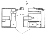
- Analogous to Fig. 1 show the Fig. 2 the half-open (here is only the wider door half 6 open) and Fig. 3 the completely open position.
- the open area formed by the open doors is designed such that the upper area 10 is freely accessible for loading the working space 2 with large workpieces.
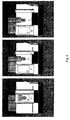
- Fig. 4 the door positions: closed, half open (the wider door 6 is open) and fully open.
Landscapes
- Engineering & Computer Science (AREA)
- General Engineering & Computer Science (AREA)
- Mechanical Engineering (AREA)
- Auxiliary Devices For Machine Tools (AREA)
- Electrical Discharge Machining, Electrochemical Machining, And Combined Machining (AREA)
Description
- Die Erfindung betrifft eine Werkzeugmaschine gemäß dem Oberbegriff des Anspruchs 1.
- Werkzeugmaschinen, insbesondere Fräs- oder Bohrmaschinen enthalten in der Regel einen Werkzeugtisch, auf dem ein zu bearbeitendes Werkstück einspannbar ist. Vor diesem Werkzeugtisch ist üblicherweise ein dreidimensional verschiebbares Werkzeug, beispielsweise ein Spindelstock mit einem Fräswerkzeug, angeordnet. Der Werkzeugtisch und die Werkzeugeinrichtung sind von einem geschlossenen Gehäuse umgeben, um die Umgebung vor umfliegenden Spänen und Kühlmittelspritzern zu schützen. Es wird somit ein Arbeitsraum gebildet. Um zu dem Arbeitsraum einen Zugang zum Werkzeug - oder Werkstückwechsel zu erhalten, ist in der Frontseite des Gehäuses eine Tür vorgesehen. Diese Türen bestehen bekanntermassen aus einer oder zwei Schiebetüren, wobei in den Schiebetüren Fenster zur Beobachtung des zu bearbeitenden Werkstückes eingesetzt sind.
- Eine solche Tür ist in der
DE 101 01 675 A1 beschrieben. Diese Werkzeugmaschine weist unter Anderem zwei gleich breite Schiebetürhälften mit jeweils einer Glasscheibe auf. - Der damit verbundene Nachteil liegt darin, dass die mittleren Seiten der gleich breiten Türhälften Griffe enthaltende Stege aufweisen, die im geschlossenen Zustand die direkte Sicht auf das Werkstück mit dem Werkzeug und im Hinblick auf den Arbeitsprozess verhindert.
- Eine andere bekannte Ausführungsform besteht darin, die Tür einstückig zu gestalten, welches aufgrund der damit verbundenen grösseren Breite bei der geöffneten Stellung ein hinderliches seitliches Überstehen bedingt und beispielsweise das seitliche Anbringen eines Peripheriegerätes verbietet.
- In der
EP 1 754 568 A1 wird eine Werkzeugmaschine beschrieben, bei der die vordere Tür in zwei gleich breite Türhälften geteilt ist und zur Vergrösserung des Arbeits- und Beladebereichs nach oben, holmenfrei ausgebildet ist. - Die Nachteile dieser Bauform entsprechen denen der zuvor erwähnten deutschen Patentschrift.
- Die
US 4 999 895 offenbart eine Aussenfrontabdeckung einer Werkzeugmaschine. Die Abdeckung weist eine Schiebetüren verschliessbare schmale Öffnung auf, die es ermöglicht, die Werkstücke geöffneten Türen hindurchzuschieben und schützt die Umgebung bei geschlossenen Türen vor umher fliegenden Spänen und Kühlmittelspritzern. Oberhalb der schmalen Öffnung befinden sich zwei weitere Türen, die den Zugang zum Werkzeug bei einem Werkzeugwechsel erleichtern. - Nachteilig an dieser Ausführungsform der Abdeckung ist jedoch die fehlende Möglichkeit das Werkstück während seiner Bearbeitung zu beobachten.
- Ausgehend von diesem Stand der Technik liegt die erfindungsgemässe Aufgabe darin, eine Gehäusetür einer Werkzeugmaschine zu schaffen, die eine ungehinderte Sicht innerhalb des mittleren Bereichs des Arbeitsraumes zulässt und somit die sichere Bearbeitung eines Werkstückes durch den Operator in optimaler Weise gestattet.
- Die Lösung der Aufgabe wird erfindungsgemäss dadurch gelöst, dass die Tür eine asymmetrische Bauweise aufweist, wobei die eine Schiebetür breiter ist als die andere Schiebetür und in der breiteren Schiebetür ein Fenster angeordnet ist, wobei der Fensterbereich über die Mitte des Arbeitsraumes reicht.
- Aufgrund der grösseren Breite der einen Türhälfte, die als Schiebetür ausgebildet sein kann, ist es in einfacher Weise gelungen, eine freie Sicht auf den Bearbeitungsprozess zu schaffen und somit einen unverzerrten Eindruck von dem Arbeitsvorgang der Werkzeugmaschine zu erhalten. Somit ist eine höhere Arbeitssicherheit gewährleistet.
- Weitere Ausgestaltungen der Erfindung sind aus den Merkmalen der Unteransprüche zu entnehmen und werden bei der Beschreibung des Ausführungsbeispiels näher erläutert.
- Die erfindungsgemässe Werkzeugmaschine ist beispielhaft in den Zeichnungen dargestellt. Es zeigen:
- Fig.1
- die Frontansicht und Draufsicht der Tür in geschlossener Stellung
- Fig.2
- die Frontansicht und Draufsicht der Tür in halboffener Stellung
- Fig.3
- die Frontansicht und Draufsicht der Tür in offener Stellung
- Fig. 4
- die Frontansicht der Werkzeugmaschine in drei Türstellungen
- Die
Fig. 1 zeigt das Werkzeugmaschinenkonzept in Front- und Draufsicht mit der Frontseite 5. Die Werkzeugmaschine 1 weist ein Gehäuse 4 auf, welches den Arbeitsraum 2 schützend umgibt. Im Arbeitsraum 2 befinden sich das Werkzeug 3 und der nicht dargestellte Werktisch mit dem Werkstück, weiches sich bekanntermassen unterhalb des Werkzeuges 3 befindet. In diesem Ausführungsbeispiel wird die Tür aus zwei Schiebetüren 6 und 7 gebildet. Die Schiebetürhälften 6 und 7 sind winkelförmig ausgestaltet mit einem oberen horizontalen 14, 14' und einem nach unten weisenden vertikalen 15, 15' Bereich. Mittels der Schienen 16 und 17 werden die Türhälften 6, 7 horizontal 16 bzw. vertikal 17 geführt. Wesentlich ist die Tatsache, dass die Breiten B1 und B2 der Türhälften unterschiedlich sind. Die Breite B1 ist so gewählt, dass sie den gesamten Mittenbereich, in dem die Bearbeitung des Werkstückes erfolgt, überdeckt. Es wird somit ermöglicht, in diese breitere Tür 6 ein Fenster 8 anzuordnen, um eine hinderungsfreie Sicht auf das Werkstück und das Werkzeug 3 während der Bearbeitung zu gewähren. Beide Türhälften 6, 7 sind durch Dichtungsmittel 9 angebracht, beispielsweise durch ein mechanisches "Labyrinth". Weiterhin ist auf der rechten Seite 11 des Maschinensockels 19 ein schwenkbarer Arm 20 für den manuell bedienbaren Steuerpult 12 angebracht. In dieserFig. 1 sind die Türen 6, 7 geschlossen. Der Fensterbereich 13 erstreckt sich über den ganzen Arbeitsbereich im Arbeitsraum 2. Im Stand der Technik wird dieser Bereich durch die Türkanten hinderlich verdeckt. - Die Türführungen sind in bekannter Weise gegen herumfliegende Späne oder Kühlwasserspritzer geschützt, beispielsweise durch schräg die Führungen überdeckende Bleche.
- Die Türhälften 6, 7 können unabhängig voneinander jeweils für sich allein oder beide gleichzeitig geöffnet oder geschlossen werden. Analog zu
Fig. 1 zeigen dieFig. 2 die halboffene (hier ist nur die breitere Türhälfte 6 geöffnet) undFig. 3 die komplett geöffnete Stellung. Der durch die geöffneten Türen gebildete offene Bereich ist so ausgestaltet, dass der obere Bereich 10 zum Bestücken des Arbeitsraumes 2 mit grossen Werkstücken frei zugänglich ist. - Zusammenfassend zeigt die
Fig. 4 die Türstellungen: geschlossen, halb offen (die breitere Tür 6 ist geöffnet) und ganz geöffnet. - Die mit dieser Erfindung verbundenen Vorteile liegen insbesondere darin, dass im Gegensatz zum Stand der Technik bezogen auf ebene Türen die Sicht auf das zu bearbeitende Werkstück hinderungsfrei erfolgt.
-
- 1
- Werkzeugmaschine
- 2
- Arbeitsraum
- 3
- Werkzeug
- 4
- Gehäuse
- 5
- Frontseite
- 6
- Breitere Schiebetür
- 7
- Schmalere Schiebetür
- 8
- Fenster
- 9
- Dichtungsmittel
- 10
- Oberer Bereich
- 11
- Seite
- 12
- Pult
- 13
- Fensterbereich
- 14
- Horizontaler Bereich von 6
- 15
- Vertikaler Bereich von 6
- 16
- Horizontale Schiene
- 17
- Vertikale Schiene
- 18
- Obere Seite
- 19
- Maschinensockel
- 20
- Schwenkbarer Arm
- B1
- Breite von 6
- B2
- Breite von 7
- 14'
- Horizontaler Bereich von 7
- 15'
- Vertikaler Bereich von 7
Claims (6)
- Werkzeugmaschine (1) mit einem in einem Arbeitsraum (2) mittig angeordneten Werkzeug (3), einem den Arbeitsraum (2) umschliessenden Gehäuse (4), welches an der Frontseite (5) mittels einer Tür (6, 7) verschliessbar ist, wobei die Tür (6, 7) zwei Schiebetüren (6, 7) aufweist die nebeneinander angeordnet sind, dadurch gekennzeichnet, dass die eine Schiebetür (6) breiter ist als die andere Schiebetür (7) und in der breiteren Schiebetür (6) ein Fenster (8) angeordnet ist, wobei der Fensterbereich (13) über die Mitte des Arbeitsraumes (2) reicht.
- Werkzeugmaschine (1) nach Anspruch 1, dadurch gekennzeichnet, dass das in der breiteren Tür (6) angeordnete Fenster (8) bei geschlossenem Zustand genau vor dem Werkzeug (3) zur besseren Einsicht angeordnet ist.
- Werkzeugmaschine (1) nach Anspruch 1 oder 2, dadurch gekennzeichnet, dass bei geschlossener Tür (6, 7) die beiden unterschiedlich breiten Schiebetüren (6, 7) Dichtungsmittel (9) aufweisen.
- Werkzeugmaschine (1) nach Anspruch 1, 2 oder 3, dadurch gekennzeichnet, dass der obere Bereich (10) des Arbeitsraumes bei geöffneter Tür (6, 7) nach oben frei zugänglich ist.
- Werkzeugmaschine (1) nach einem der vorherigen Ansprüche, dadurch gekennzeichnet, dass beide Schiebetüren (6, 7) unabhängig voneinander verschliessbar sind.
- Werkzeugmaschine nach einem der vorherigen Ansprüche, dadurch gekennzeichnet, dass auf der Gehäuseseite (11) der schmaleren Schiebetür (7) ein schwenkbarer Pult (12) für die manuelle Steuerung der Werkzeugmaschine (1) angeordnet ist.
Priority Applications (4)
| Application Number | Priority Date | Filing Date | Title |
|---|---|---|---|
| ES08105429T ES2362316T3 (es) | 2008-09-25 | 2008-09-25 | Puerta para máquina herramienta. |
| DE502008002822T DE502008002822D1 (de) | 2008-09-25 | 2008-09-25 | Tür für Werkzeugmaschinen |
| EP08105429A EP2168716B1 (de) | 2008-09-25 | 2008-09-25 | Tür für Werkzeugmaschinen |
| AT08105429T ATE500922T1 (de) | 2008-09-25 | 2008-09-25 | Tür für werkzeugmaschinen |
Applications Claiming Priority (1)
| Application Number | Priority Date | Filing Date | Title |
|---|---|---|---|
| EP08105429A EP2168716B1 (de) | 2008-09-25 | 2008-09-25 | Tür für Werkzeugmaschinen |
Publications (2)
| Publication Number | Publication Date |
|---|---|
| EP2168716A1 EP2168716A1 (de) | 2010-03-31 |
| EP2168716B1 true EP2168716B1 (de) | 2011-03-09 |
Family
ID=40352084
Family Applications (1)
| Application Number | Title | Priority Date | Filing Date |
|---|---|---|---|
| EP08105429A Active EP2168716B1 (de) | 2008-09-25 | 2008-09-25 | Tür für Werkzeugmaschinen |
Country Status (4)
| Country | Link |
|---|---|
| EP (1) | EP2168716B1 (de) |
| AT (1) | ATE500922T1 (de) |
| DE (1) | DE502008002822D1 (de) |
| ES (1) | ES2362316T3 (de) |
Family Cites Families (5)
| Publication number | Priority date | Publication date | Assignee | Title |
|---|---|---|---|---|
| JPH024739U (de) * | 1988-06-22 | 1990-01-12 | ||
| DE10101675A1 (de) | 2001-01-10 | 2002-07-18 | Chiron Werke Gmbh | Werkzeugmaschine mit verschwenkbarem Kommandopult |
| EP1754568A1 (de) * | 2005-08-19 | 2007-02-21 | Mikron Agie Charmilles AG | Werkzeugmaschine mit automatischer Abdeckung im Dachbereich |
| US20070068080A1 (en) * | 2005-09-24 | 2007-03-29 | Alexander Vigdorovich | Expandable door |
| DE202007018592U1 (de) * | 2007-09-07 | 2008-11-20 | Deckel Maho Pfronten Gmbh | Schutzkabine für Werkzeugmaschinen |
-
2008
- 2008-09-25 AT AT08105429T patent/ATE500922T1/de active
- 2008-09-25 EP EP08105429A patent/EP2168716B1/de active Active
- 2008-09-25 ES ES08105429T patent/ES2362316T3/es active Active
- 2008-09-25 DE DE502008002822T patent/DE502008002822D1/de active Active
Also Published As
| Publication number | Publication date |
|---|---|
| EP2168716A1 (de) | 2010-03-31 |
| DE502008002822D1 (de) | 2011-04-21 |
| ES2362316T3 (es) | 2011-07-01 |
| ATE500922T1 (de) | 2011-03-15 |
Similar Documents
| Publication | Publication Date | Title |
|---|---|---|
| DE102012018226A1 (de) | Werkzeugmaschine mit Schutzabdeckung | |
| DE3605983C2 (de) | ||
| EP3659744B1 (de) | Werkzeugmaschine mit schräg gestelltem werkstücktisch | |
| EP0803320A1 (de) | Werkzeugmaschine mit einer Lamellentüre | |
| DE102018208466A1 (de) | Maschinenwerkzeug | |
| DE102004048037B4 (de) | Werkzeugmaschine | |
| WO2010089051A1 (de) | Bearbeitungszentrum | |
| EP0742073B1 (de) | Maschinenzentrum mit Werkstückwechsler | |
| EP3129270B1 (de) | Schienenfahrzeug | |
| EP2168716A1 (de) | Tür für Werkzeugmaschinen | |
| DE3329266A1 (de) | Von einem industrie-roboter bediente werkzeugmaschine | |
| DE10125186B4 (de) | Schutzvorrichtung | |
| DE8412399U1 (de) | Spritzschutzkabine für Fräs- und Bohrmaschinen | |
| DE202006009653U1 (de) | Bearbeitungszentrum | |
| DE102012017027A1 (de) | Werkzeugmaschine mit Schiebetür | |
| DD204873A1 (de) | Arbeitsraumabschirmung fuer eine werkzeugmaschine, insbesondere fraesmaschine | |
| DE9202074U1 (de) | Spritzschutz-Verkleidung für eine Werkzeugmaschine | |
| DE202017105385U1 (de) | Gehäuse für eine Bearbeitungsmaschine | |
| DE102012217666A1 (de) | Leit- und Zugspindeldrehmaschine mit Spannfutterschutzhaube | |
| DE202004009351U1 (de) | Elektronisch steuerbare Drehmaschine | |
| AT517190B1 (de) | Maschine für das Schneiden von Platten | |
| DE102006032619B4 (de) | Fahrständer-Werkzeugmaschine mit einem neuen Arbeitsraumkonzept | |
| DE102020134556B4 (de) | Vorrichtung zum Bereitstellen von Werkzeugen für eine Werkzeugmaschine | |
| DE19516851C2 (de) | Schutzverkleidung für eine Werkzeugmaschine | |
| DE846790C (de) | Einrichtung fuer Holzbearbeitungsmaschinen, insbesondere Fraesmaschinen |
Legal Events
| Date | Code | Title | Description |
|---|---|---|---|
| PUAI | Public reference made under article 153(3) epc to a published international application that has entered the european phase |
Free format text: ORIGINAL CODE: 0009012 |
|
| AK | Designated contracting states |
Kind code of ref document: A1 Designated state(s): AT BE BG CH CY CZ DE DK EE ES FI FR GB GR HR HU IE IS IT LI LT LU LV MC MT NL NO PL PT RO SE SI SK TR |
|
| AX | Request for extension of the european patent |
Extension state: AL BA MK RS |
|
| 17P | Request for examination filed |
Effective date: 20100504 |
|
| 17Q | First examination report despatched |
Effective date: 20100526 |
|
| GRAP | Despatch of communication of intention to grant a patent |
Free format text: ORIGINAL CODE: EPIDOSNIGR1 |
|
| AKX | Designation fees paid |
Designated state(s): AT BE BG CH CY CZ DE DK EE ES FI FR GB GR HR HU IE IS IT LI LT LU LV MC MT NL NO PL PT RO SE SI SK TR |
|
| GRAS | Grant fee paid |
Free format text: ORIGINAL CODE: EPIDOSNIGR3 |
|
| GRAA | (expected) grant |
Free format text: ORIGINAL CODE: 0009210 |
|
| AK | Designated contracting states |
Kind code of ref document: B1 Designated state(s): AT BE BG CH CY CZ DE DK EE ES FI FR GB GR HR HU IE IS IT LI LT LU LV MC MT NL NO PL PT RO SE SI SK TR |
|
| REG | Reference to a national code |
Ref country code: GB Ref legal event code: FG4D Free format text: NOT ENGLISH |
|
| REG | Reference to a national code |
Ref country code: CH Ref legal event code: EP Ref country code: CH Ref legal event code: NV Representative=s name: GEORG FISCHER AG |
|
| REG | Reference to a national code |
Ref country code: IE Ref legal event code: FG4D Free format text: LANGUAGE OF EP DOCUMENT: GERMAN |
|
| REF | Corresponds to: |
Ref document number: 502008002822 Country of ref document: DE Date of ref document: 20110421 Kind code of ref document: P |
|
| REG | Reference to a national code |
Ref country code: DE Ref legal event code: R096 Ref document number: 502008002822 Country of ref document: DE Effective date: 20110421 |
|
| REG | Reference to a national code |
Ref country code: ES Ref legal event code: FG2A Ref document number: 2362316 Country of ref document: ES Kind code of ref document: T3 Effective date: 20110701 |
|
| REG | Reference to a national code |
Ref country code: NL Ref legal event code: VDEP Effective date: 20110309 |
|
| PG25 | Lapsed in a contracting state [announced via postgrant information from national office to epo] |
Ref country code: NO Free format text: LAPSE BECAUSE OF FAILURE TO SUBMIT A TRANSLATION OF THE DESCRIPTION OR TO PAY THE FEE WITHIN THE PRESCRIBED TIME-LIMIT Effective date: 20110609 Ref country code: HR Free format text: LAPSE BECAUSE OF FAILURE TO SUBMIT A TRANSLATION OF THE DESCRIPTION OR TO PAY THE FEE WITHIN THE PRESCRIBED TIME-LIMIT Effective date: 20110309 Ref country code: GR Free format text: LAPSE BECAUSE OF FAILURE TO SUBMIT A TRANSLATION OF THE DESCRIPTION OR TO PAY THE FEE WITHIN THE PRESCRIBED TIME-LIMIT Effective date: 20110610 Ref country code: LT Free format text: LAPSE BECAUSE OF FAILURE TO SUBMIT A TRANSLATION OF THE DESCRIPTION OR TO PAY THE FEE WITHIN THE PRESCRIBED TIME-LIMIT Effective date: 20110309 Ref country code: LV Free format text: LAPSE BECAUSE OF FAILURE TO SUBMIT A TRANSLATION OF THE DESCRIPTION OR TO PAY THE FEE WITHIN THE PRESCRIBED TIME-LIMIT Effective date: 20110309 Ref country code: SE Free format text: LAPSE BECAUSE OF FAILURE TO SUBMIT A TRANSLATION OF THE DESCRIPTION OR TO PAY THE FEE WITHIN THE PRESCRIBED TIME-LIMIT Effective date: 20110309 |
|
| LTIE | Lt: invalidation of european patent or patent extension |
Effective date: 20110309 |
|
| PG25 | Lapsed in a contracting state [announced via postgrant information from national office to epo] |
Ref country code: FI Free format text: LAPSE BECAUSE OF FAILURE TO SUBMIT A TRANSLATION OF THE DESCRIPTION OR TO PAY THE FEE WITHIN THE PRESCRIBED TIME-LIMIT Effective date: 20110309 Ref country code: BG Free format text: LAPSE BECAUSE OF FAILURE TO SUBMIT A TRANSLATION OF THE DESCRIPTION OR TO PAY THE FEE WITHIN THE PRESCRIBED TIME-LIMIT Effective date: 20110609 Ref country code: CY Free format text: LAPSE BECAUSE OF FAILURE TO SUBMIT A TRANSLATION OF THE DESCRIPTION OR TO PAY THE FEE WITHIN THE PRESCRIBED TIME-LIMIT Effective date: 20110309 Ref country code: NL Free format text: LAPSE BECAUSE OF FAILURE TO SUBMIT A TRANSLATION OF THE DESCRIPTION OR TO PAY THE FEE WITHIN THE PRESCRIBED TIME-LIMIT Effective date: 20110309 Ref country code: SI Free format text: LAPSE BECAUSE OF FAILURE TO SUBMIT A TRANSLATION OF THE DESCRIPTION OR TO PAY THE FEE WITHIN THE PRESCRIBED TIME-LIMIT Effective date: 20110309 |
|
| REG | Reference to a national code |
Ref country code: IE Ref legal event code: FD4D |
|
| PG25 | Lapsed in a contracting state [announced via postgrant information from national office to epo] |
Ref country code: EE Free format text: LAPSE BECAUSE OF FAILURE TO SUBMIT A TRANSLATION OF THE DESCRIPTION OR TO PAY THE FEE WITHIN THE PRESCRIBED TIME-LIMIT Effective date: 20110309 Ref country code: IE Free format text: LAPSE BECAUSE OF FAILURE TO SUBMIT A TRANSLATION OF THE DESCRIPTION OR TO PAY THE FEE WITHIN THE PRESCRIBED TIME-LIMIT Effective date: 20110309 Ref country code: PT Free format text: LAPSE BECAUSE OF FAILURE TO SUBMIT A TRANSLATION OF THE DESCRIPTION OR TO PAY THE FEE WITHIN THE PRESCRIBED TIME-LIMIT Effective date: 20110711 |
|
| PG25 | Lapsed in a contracting state [announced via postgrant information from national office to epo] |
Ref country code: CZ Free format text: LAPSE BECAUSE OF FAILURE TO SUBMIT A TRANSLATION OF THE DESCRIPTION OR TO PAY THE FEE WITHIN THE PRESCRIBED TIME-LIMIT Effective date: 20110309 Ref country code: IS Free format text: LAPSE BECAUSE OF FAILURE TO SUBMIT A TRANSLATION OF THE DESCRIPTION OR TO PAY THE FEE WITHIN THE PRESCRIBED TIME-LIMIT Effective date: 20110709 Ref country code: SK Free format text: LAPSE BECAUSE OF FAILURE TO SUBMIT A TRANSLATION OF THE DESCRIPTION OR TO PAY THE FEE WITHIN THE PRESCRIBED TIME-LIMIT Effective date: 20110309 Ref country code: RO Free format text: LAPSE BECAUSE OF FAILURE TO SUBMIT A TRANSLATION OF THE DESCRIPTION OR TO PAY THE FEE WITHIN THE PRESCRIBED TIME-LIMIT Effective date: 20110309 |
|
| PLBE | No opposition filed within time limit |
Free format text: ORIGINAL CODE: 0009261 |
|
| STAA | Information on the status of an ep patent application or granted ep patent |
Free format text: STATUS: NO OPPOSITION FILED WITHIN TIME LIMIT |
|
| 26N | No opposition filed |
Effective date: 20111212 |
|
| PG25 | Lapsed in a contracting state [announced via postgrant information from national office to epo] |
Ref country code: PL Free format text: LAPSE BECAUSE OF FAILURE TO SUBMIT A TRANSLATION OF THE DESCRIPTION OR TO PAY THE FEE WITHIN THE PRESCRIBED TIME-LIMIT Effective date: 20110309 Ref country code: DK Free format text: LAPSE BECAUSE OF FAILURE TO SUBMIT A TRANSLATION OF THE DESCRIPTION OR TO PAY THE FEE WITHIN THE PRESCRIBED TIME-LIMIT Effective date: 20110309 |
|
| BERE | Be: lapsed |
Owner name: MIKRON AGIE CHARMILLES AG Effective date: 20110930 |
|
| REG | Reference to a national code |
Ref country code: DE Ref legal event code: R097 Ref document number: 502008002822 Country of ref document: DE Effective date: 20111212 |
|
| PG25 | Lapsed in a contracting state [announced via postgrant information from national office to epo] |
Ref country code: MC Free format text: LAPSE BECAUSE OF NON-PAYMENT OF DUE FEES Effective date: 20110930 |
|
| PG25 | Lapsed in a contracting state [announced via postgrant information from national office to epo] |
Ref country code: BE Free format text: LAPSE BECAUSE OF NON-PAYMENT OF DUE FEES Effective date: 20110930 |
|
| PG25 | Lapsed in a contracting state [announced via postgrant information from national office to epo] |
Ref country code: MT Free format text: LAPSE BECAUSE OF FAILURE TO SUBMIT A TRANSLATION OF THE DESCRIPTION OR TO PAY THE FEE WITHIN THE PRESCRIBED TIME-LIMIT Effective date: 20110309 |
|
| PG25 | Lapsed in a contracting state [announced via postgrant information from national office to epo] |
Ref country code: LU Free format text: LAPSE BECAUSE OF NON-PAYMENT OF DUE FEES Effective date: 20110925 |
|
| PG25 | Lapsed in a contracting state [announced via postgrant information from national office to epo] |
Ref country code: TR Free format text: LAPSE BECAUSE OF FAILURE TO SUBMIT A TRANSLATION OF THE DESCRIPTION OR TO PAY THE FEE WITHIN THE PRESCRIBED TIME-LIMIT Effective date: 20110309 |
|
| PG25 | Lapsed in a contracting state [announced via postgrant information from national office to epo] |
Ref country code: HU Free format text: LAPSE BECAUSE OF FAILURE TO SUBMIT A TRANSLATION OF THE DESCRIPTION OR TO PAY THE FEE WITHIN THE PRESCRIBED TIME-LIMIT Effective date: 20110309 |
|
| REG | Reference to a national code |
Ref country code: AT Ref legal event code: MM01 Ref document number: 500922 Country of ref document: AT Kind code of ref document: T Effective date: 20130925 |
|
| PGFP | Annual fee paid to national office [announced via postgrant information from national office to epo] |
Ref country code: ES Payment date: 20140926 Year of fee payment: 7 |
|
| PG25 | Lapsed in a contracting state [announced via postgrant information from national office to epo] |
Ref country code: AT Free format text: LAPSE BECAUSE OF NON-PAYMENT OF DUE FEES Effective date: 20130925 |
|
| REG | Reference to a national code |
Ref country code: FR Ref legal event code: PLFP Year of fee payment: 8 |
|
| PGFP | Annual fee paid to national office [announced via postgrant information from national office to epo] |
Ref country code: FR Payment date: 20150922 Year of fee payment: 8 |
|
| PG25 | Lapsed in a contracting state [announced via postgrant information from national office to epo] |
Ref country code: ES Free format text: LAPSE BECAUSE OF NON-PAYMENT OF DUE FEES Effective date: 20150926 |
|
| REG | Reference to a national code |
Ref country code: FR Ref legal event code: ST Effective date: 20170531 |
|
| PG25 | Lapsed in a contracting state [announced via postgrant information from national office to epo] |
Ref country code: FR Free format text: LAPSE BECAUSE OF NON-PAYMENT OF DUE FEES Effective date: 20160930 |
|
| REG | Reference to a national code |
Ref country code: CH Ref legal event code: PFA Owner name: GF MACHINING SOIUTIONS AG, CH Free format text: FORMER OWNER: MIKRON AGIE CHARMILLES AG, CH |
|
| REG | Reference to a national code |
Ref country code: DE Ref legal event code: R081 Ref document number: 502008002822 Country of ref document: DE Owner name: GF MACHINING SOLUTIONS AG, CH Free format text: FORMER OWNER: MIKRON AGIE CHARMILLES AG, NIDAU, CH |
|
| P01 | Opt-out of the competence of the unified patent court (upc) registered |
Effective date: 20230529 |
|
| REG | Reference to a national code |
Ref country code: CH Ref legal event code: U11 Free format text: ST27 STATUS EVENT CODE: U-0-0-U10-U11 (AS PROVIDED BY THE NATIONAL OFFICE) Effective date: 20251001 |
|
| PGFP | Annual fee paid to national office [announced via postgrant information from national office to epo] |
Ref country code: DE Payment date: 20250919 Year of fee payment: 18 |
|
| PGFP | Annual fee paid to national office [announced via postgrant information from national office to epo] |
Ref country code: IT Payment date: 20250923 Year of fee payment: 18 |
|
| PGFP | Annual fee paid to national office [announced via postgrant information from national office to epo] |
Ref country code: GB Payment date: 20250918 Year of fee payment: 18 |
|
| PGFP | Annual fee paid to national office [announced via postgrant information from national office to epo] |
Ref country code: CH Payment date: 20251001 Year of fee payment: 18 |