EP2168362B1 - Schiebemechanismus für ein elektronisches gerät - Google Patents
Schiebemechanismus für ein elektronisches gerät Download PDFInfo
- Publication number
- EP2168362B1 EP2168362B1 EP08776512.9A EP08776512A EP2168362B1 EP 2168362 B1 EP2168362 B1 EP 2168362B1 EP 08776512 A EP08776512 A EP 08776512A EP 2168362 B1 EP2168362 B1 EP 2168362B1
- Authority
- EP
- European Patent Office
- Prior art keywords
- plate
- resilient actuator
- connecting end
- actuator
- profile
- Prior art date
- Legal status (The legal status is an assumption and is not a legal conclusion. Google has not performed a legal analysis and makes no representation as to the accuracy of the status listed.)
- Not-in-force
Links
- 230000007246 mechanism Effects 0.000 title claims description 61
- 238000000034 method Methods 0.000 claims description 4
- 238000004519 manufacturing process Methods 0.000 claims description 2
- 238000005096 rolling process Methods 0.000 claims description 2
- 230000008859 change Effects 0.000 description 6
- 230000008901 benefit Effects 0.000 description 4
- 230000006870 function Effects 0.000 description 4
- 230000001413 cellular effect Effects 0.000 description 2
- 230000009977 dual effect Effects 0.000 description 2
- 238000012986 modification Methods 0.000 description 2
- 230000004048 modification Effects 0.000 description 2
- 238000000926 separation method Methods 0.000 description 2
- 230000006835 compression Effects 0.000 description 1
- 238000007906 compression Methods 0.000 description 1
- 230000001419 dependent effect Effects 0.000 description 1
- 238000011161 development Methods 0.000 description 1
- 230000018109 developmental process Effects 0.000 description 1
Images







Classifications
-
- H—ELECTRICITY
- H04—ELECTRIC COMMUNICATION TECHNIQUE
- H04M—TELEPHONIC COMMUNICATION
- H04M1/00—Substation equipment, e.g. for use by subscribers
- H04M1/02—Constructional features of telephone sets
- H04M1/0202—Portable telephone sets, e.g. cordless phones, mobile phones or bar type handsets
- H04M1/0206—Portable telephones comprising a plurality of mechanically joined movable body parts, e.g. hinged housings
- H04M1/0208—Portable telephones comprising a plurality of mechanically joined movable body parts, e.g. hinged housings characterized by the relative motions of the body parts
- H04M1/0235—Slidable or telescopic telephones, i.e. with a relative translation movement of the body parts; Telephones using a combination of translation and other relative motions of the body parts
- H04M1/0237—Sliding mechanism with one degree of freedom
-
- H—ELECTRICITY
- H04—ELECTRIC COMMUNICATION TECHNIQUE
- H04M—TELEPHONIC COMMUNICATION
- H04M1/00—Substation equipment, e.g. for use by subscribers
- H04M1/02—Constructional features of telephone sets
- H04M1/0202—Portable telephone sets, e.g. cordless phones, mobile phones or bar type handsets
- H04M1/0206—Portable telephones comprising a plurality of mechanically joined movable body parts, e.g. hinged housings
- H04M1/0241—Portable telephones comprising a plurality of mechanically joined movable body parts, e.g. hinged housings using relative motion of the body parts to change the operational status of the telephone set, e.g. switching on/off, answering incoming call
- H04M1/0245—Portable telephones comprising a plurality of mechanically joined movable body parts, e.g. hinged housings using relative motion of the body parts to change the operational status of the telephone set, e.g. switching on/off, answering incoming call using open/close detection
-
- H—ELECTRICITY
- H04—ELECTRIC COMMUNICATION TECHNIQUE
- H04M—TELEPHONIC COMMUNICATION
- H04M1/00—Substation equipment, e.g. for use by subscribers
- H04M1/02—Constructional features of telephone sets
- H04M1/0202—Portable telephone sets, e.g. cordless phones, mobile phones or bar type handsets
- H04M1/026—Details of the structure or mounting of specific components
- H04M1/0264—Details of the structure or mounting of specific components for a camera module assembly
Definitions
- the invention relates to an electronic device and, more particularly, to a slide mechanism for an electronic device.
- WO 2006098590 relates to a sliding unit and an electronic device using the same, which can connect, in sliding manner, a transmitting part with a receiving part of a cellular phone that opens/closes the transmitting part and the receiving part in sliding manner, by connecting each section with the transmitting part and the receiving part of the sliding-type cellular phone.
- Nokia “N95-1: Get started” (www.nokia.com, retrieved from internet on 10 August 2010: URL: http://nds1.nokia.com/phones/files/guides/Nokia_N95-1_release2_GS_en.pdf ) relates to a mobile phone which has slidable housings.
- JP 2005269070 describes a semiautomatic slider unit, for sliding a first case and a second case relatively in one direction, comprising a cam member fixed to the side of any one of the first and second cases, a rotating member fixed rotatably to the cam member and supported rotatably in an elongated guide hole provided on the side of the other of the first and second cases, and a slider provided between the rotating member and the cam member while butting against the cam part of the cam member at the forward end and being urged to slide in one direction.
- the prior art does not provide for a second connecting end of the resilient actuator configured to be movably connected to a slot of a second plate and configured to slide or move or roll along a first profile of a cam section, such that:
- the invention is directed to an apparatus and a method as set out in the independent claims.
- Advantageous embodiments are set out in the dependent claims.
- a portable electronic device in accordance with one aspect described herein, includes a housing, electronic circuitry, and a slide mechanism.
- the housing includes a first housing member and a second housing member.
- the electronic circuitry is mounted in the housing.
- the slide mechanism is between the first housing member and the second housing member.
- the slide mechanism includes a cam section and an actuator.
- the cam section is configured to be connected to a first housing member.
- the actuator is configured to contact a first side of the cam section.
- a first end of the actuator is configured to be movably connected to the first housing member.
- a second end of the actuator is configured to be movably connected to a second housing member.
- the second housing member is configured to be movable in a first direction when the actuator moves in a direction away from the cam section.
- the second housing member is configured to be movable in a second direction when the actuator moves along the first side of the cam section.
- a portable electronic device in accordance with another aspect described herein.
- the portable electronic device includes a housing, electronic circuitry, and a slide connection.
- the housing includes a first housing member and a second housing member.
- the electronic circuitry is mounted in the housing.
- the slide connection is adapted to slidably connect the second housing member to the first housing member.
- the slide connection is adapted to semi-automatically slide when an end of at least one of the housing members is moved above a top end of the portable electronic device.
- the slide connection is adapted to slide when an opposite end of the at least one housing member is moved below a bottom end of the portable electronic device.
- a portable electronic device in accordance with another aspect described herein.
- the portable electronic device includes a housing, electronic circuitry, and an actuator.
- the housing includes a first housing member and a second housing member.
- the electronic circuitry is mounted in the housing.
- the actuator has a first end and a second end. The first end is rotatably connected to the first housing member. The second end is slidably connected to the second housing member.
- the second housing member is configured to be movable in a first longitudinal direction relative to the first housing member when the actuator rotates in a first direction of rotation.
- the second housing member is configured to be movable in a second different longitudinal direction relative to the first housing member when the actuator rotates in a second different direction of rotation.
- a method of manufacturing a portable electronic device is disclosed.
- a first housing member is provided.
- a cam section is connected to the first housing member.
- a first end of an actuator is rotatably connected to the first housing member.
- a second end of the actuator is slidably connected to a second housing member. The second end is configured to contact a side of the cam section.
- Electronic circuitry is installed within at least one of the housing members.
- FIG. 1 there is shown a perspective view of a portable electronic device 10 incorporating features of the invention.
- a portable electronic device 10 incorporating features of the invention.
- the invention will be described with reference to the exemplary embodiments shown in the drawings, it should be understood that the invention can be embodied in many alternate forms of embodiments.
- any suitable size, shape or type of elements or materials could be used.
- the device 10 is a multi function portable electronic device.
- features of the exemplary embodiment of this invention could be used in any suitable type of hand-held portable electronic device such as a mobile phone, a gaming device, a music player, or a PDA, for example.
- the device 10 can include features or applications such as a camera, a music player, a game player, or an internet browser, for example.
- the device 10 generally comprises a housing 12 and electronic circuitry 14.
- the electronic circuitry 14 includes, for example, a transceiver, a controller such as a microprocessor, a memory, etc.
- the housing 12 includes a first housing member 16 and a second housing member 18. It should be noted that in alternate embodiments, more than two housing members could be provided.
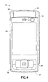
- the second housing member 18 is movably connected to the first housing member 16. More specifically, the second housing member 18 is slidably mounted to the first housing member 16 between a closed position as shown in Figs. 1 and 2 , a first open position as shown in Fig. 3 , and a second open position as shown in Fig. 4 .
- the first housing member 16 comprises a first user input region 20 at a first end 22 of the first housing member 16.
- the first user input region 20 may be a keyboard, a keypad, or a keymat, for example. However, it should be noted that alternate embodiments may provide any suitable type of user input region.
- the first user input region 20 is visible and accessible when the device 10 is in the first open position. In this first open position, a first end 23 of the second housing member 18 is above a top end 25 of the device 10.
- the first housing member 16 comprises a second user input region 24 at a second end 26 of the first housing member 16.
- the second user input region 24 may comprise control buttons or a keypad, for example. However, it should be noted that alternate embodiments may provide any suitable type of user input region.
- the second user input region 24 is visible and accessible when the device 10 is in the second open position. In this second open position, a second end 27 of the second housing member 18 is above a bottom end 29 of the device 10.
- the second housing member 18 generally comprises a display screen 28 and a third user input region 30.
- the third user input region 30 may comprise a multi-function key and control keys, for example. However, it should be noted that alternate embodiments may provide any suitable type of user input region.
- the second housing member may comprise a camera 32, a light sensor 34, and an ear piece 36, for example.
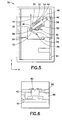
- the slide mechanism 38 in accordance with a first embodiment of the invention.
- the slide mechanism (or slide connection) 38 comprises a first plate 40, a second plate 42, and a spring actuator 44.
- the first plate 40 is configured to be connected to the first housing member 16.
- the second plate 42 is configured to be connected to the second housing member 18.
- the plates 40, 42 may be connected to the housing members 16, 18 by any suitable means. It should be noted that in an alternate embodiment, the plates 40, 42 may be integrally formed with the housing members 16, 18.
- the slide mechanism 38 is between the first plate 40 and the second plate 42.
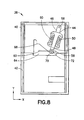
- the second plate 42 (and the connected second housing member 18) is slidably mounted to the first plate 40 (and the first housing member 16) between the closed position as shown in Fig. 5 (and also shown in Figs. 1-2 ), the first open position as shown in Fig. 7 (and also shown in Fig. 3 ), and the second open position as shown in Fig. 8 (and also shown in Fig. 4 ).
- the spring actuator 44 is disposed between the first plate 40 and the second plate 42.
- the spring actuator comprises a first spring frame member 46, a second spring frame member 48, and spring members 50.
- the spring members 50 may be coil springs for example. However, alternate embodiments may provide any suitable type springs. Additionally, it should be noted that the actuator 44 does not require springs or spring members. Instead, the actuator 44 may comprise any suitable resiliently deflectable (or resiliently flexible) members. In the embodiment shown, the spring actuator 44 has two spring members, or resilient members, 50. However, in alternate embodiments, any number of spring members could be provided. Opposite ends of the spring members 50 are connected to mount ends 52, 54 of the spring frame members 46, 48.
- the first spring frame member 46 and the second spring frame member 48 are slidably connected to each other such that a spring force of the spring members 50 may be exerted on the mount ends 52, 54.
- a connecting end 56 of the first spring frame member 46 is rotatably connected to the first plate 40.
- the connecting end 56 may be attached to first plate, or first module, 40 by riveting or any other suitable method that allows rotational movement.
- a connecting end 58 of the second spring frame member 48 is slidably connected to a slot 60 of the second plate 42.
- the connecting end 58 may be attached to the second plate, or second module, 42 by riveting (see rivet 62 in Fig. 6 ) or any other suitable method that allows rotational movement, linear sliding, and moving in the slot 60.
- the slots 60 may comprise a slot having any suitable shape or orientation.
- the slide mechanism 38 further comprises a cam section 64 attached to the first plate 40.
- the cam section 40 may be attached to the plate 40 by any suitable means. However, alternate embodiments may provide for a cam section integrally formed with the first plate.
- the cam section 64 comprises a first side, or first profile, 66.
- the first side 66 comprises a generally angled shape extending between two stop regions 68, 70.
- alternate embodiments may comprise a cam section having any suitable profile shape for contacting the spring actuator 44.
- the connecting end 58 of the second spring frame member 48 is configured to slide or move along the first side 66 of the cam section 64. Any suitable configuration allowing for the connecting end 58 to slide or roll between the stop regions 68, 70 of the first side may be provided, such as a roller 72 for example.
- the slide mechanism 38 allows for semi-automatic movement of the housing members 16, 18.
- a user would initiate a "long stroke" movement by pushing the second housing member in a vertical direction as shown by the Y-direction arrow 74. This moves the second plate 42 in the Y-direction, and moves the spring frame members 46, 48 against the force of the spring members 50.
- the connecting end 56 rotates about the connection to the plate 40, the connecting end 58 rotates within the slot 60, and the sprint actuator 44 generally rotates in a clockwise fashion (wherein the connecting end 58 moves in a first direction of rotation) between the positions of Fig. 5 and Fig. 7 .
- the mount ends 52, 54 reach their greatest separation distance and then move towards each other with assistance of the spring force.
- the spring assisted relative movement of the spring frame members 46, 48 provides the semi-automatic movement between the housing members 16, 18.
- the semi-automatic movement comprises a first portion of the movement which is manual (by the user overcoming the force of the springs) and a second portion of the movement which is automatic by the force of the springs acting in the desired direction.
- first housing member being offset from the second housing member in the longitudinal direction (Y-direction 74) and allows access to the first input region 20.
- initial manual movement may be performed by hand or by a trigger for example.
- the offset or opening length may be any suitable distance such as 30 mm for example. This opening length or "long stroke" can vary in different embodiments.
- a user would initiate a "short stroke" movement by pushing the second housing member in a vertical direction opposite to the Y-direction arrow 74. This moves the second plate 42 in the direction opposite to the y-direction, and moves the spring frame members 46, 48 against the force of the spring members 50.
- This movement is provided as the connecting end 56 rotates about the connection to the plate 40, the connecting end 58 rotates along the length of the slot 60, and the sprint actuator 44 generally rotates in a counterclockwise fashion (wherein the connecting end 58 moves in a second different direction of rotation) between the positions of Fig. 5 and Fig. 8 .
- the mount ends 52, 54 Approximately half way through the movement, the mount ends 52, 54, reach their greatest separation distance and then move towards each other with assistance of the spring force.
- the spring assisted relative movement of the spring frame members 46, 48 provides the semi-automatic movement between the housing members 16, 18.
- the semi-automatic movement comprises a first portion of the movement which is manual (by the user overcoming the force of the springs) and a second portion of the movement which is automatic by the force of the springs acting in the desired direction.
- the initial manual movement may be performed by hand or by a trigger for example.
- This "short stroke” movement moves the connecting end 58 from the first stop region 68 of the cam section 64 to the second stop region 70 (direction 76) of the cam section 64.
- the offset or opening length may be any suitable distance such as 12mm for example. This opening length or "short stroke” can vary in different embodiments.
- the opposite movements are carried out in a similar fashion as the movements described above.
- the movement stops at a middle locking position automatically.
- the "stop" movement is created by a certain combination of spring force of the spring members 50, angle of the slot 60, and the cam profile 66.
- the "short stoke” movement may not be a semi-automatic movement due to certain combinations of the spring members 50, the cam profile 66, and the angle of the slot 60 or because the short stroke is much longer than about 12mm.
- the first portion and/or the second portion of the "short stroke” movement may comprise a manual movement.
- the portion of the movement returning the housing members 16, 18 to the middle locking position may comprise a manual movement.
- the invention relates to a semi-automatic dual slide mechanism for a device 10.
- a semi-automatic dual slide mechanism for a device 10.
- One possible use would be for opening and closing a slide phone, thus opening and closing the first user input region 20, such as an ITU keymat for example, wherein the rotation of the spring actuator 44 away from the cam section 64 is used to create semi-automatic movement.
- Another possible use would be for opening and closing a slide phone, thus opening and closing the second user input region 24 wherein the rotation of the spring actuator 44 along the cam profile 66 is used to create the semi-automatic movement.
- multi-movements (more than two movements) of the housing members 16, 18 to same direction or different directions could also be provided by the disclosed slide mechanism.
- the disclosed slide mechanism provides slide movement in the vertical/longitudinal direction (Y-direction 74). However, it should be noted that the slide mechanism may provide additional slide movements in any suitable direction. Additionally, the disclosed slide mechanism provides the novelty and advantage of combining the two spring assisted sliding principles of the turning spring principle (or "long stroke” movement) and the cam/spring principle (or “short stroke” movement) while using the same spring actuator.
- the spring force typically is about 90 degrees relative to the sliding direction. Whereas in the invention the spring force turns between about 30 to about 60 degrees in the cam assisted part of the movement.
- the whole sliding mechanism has the advantage of the turning spring principle where the spring force mainly works in or against the sliding direction (but which has only two end positions). And the cam/spring principle which has multiple end/rest positions (but where the spring force needs to be turned about 90 degrees by help of the cam and therefore is a less efficient and less comfortable.)
- the disclosed slide mechanism provides excellent semi-auto function in opening and closing of slide phone when opening and closing ITU keymat.
- the movement down or “short stroke” movement
- actuator will follow the profile by sliding or with roller.
- revealing and hiding ITU-keys with help of excellent semi-auto function is big advantage. This may result in commercial value wherein disclosed slide mechanism may be used across all suitable applications and competitors (including all mobile phone manufacturers) realize the benefits by this concept.
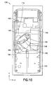
- a slide mechanism 138 in accordance with a second embodiment of the invention.
- the slide mechanism 138 is similar to the slide mechanism 38.
- the slide mechanism 138 comprises a first plate 140, a second plate 142, and a spring actuator 144 as described above with respect to the first embodiment.
- One difference between the slide mechanism 138 and the slide mechanism 38 is the location and shape of the cam section 164.
- the cam section 164 is adjacent to a lateral side of the first plate 140.
- the profile 166 of the cam section 164 comprises a non-linear shape.
- the slot 160 comprises an angled configuration.
- the spring actuator 144 comprises one spring member 150.
- the spring member 150 may be a coil spring for example. However, alternate embodiments may provide any suitable type spring. Additionally, it should be noted that the actuator 144 does not require a spring or a spring member. Instead, the actuator 144 may comprise any suitable resiliently deflectable (or resiliently flexible) member. In the embodiment shown, the spring actuator 144 has one spring member, or resilient member, 150. However, in alternate embodiments, any number of spring members could be provided.
- Figs. 9 and 10 illustrate a closed position.
- a user would initiate a "long stroke" movement by pushing the second housing member in a vertical direction as shown by the Y-direction arrow 174. This moves the second plate 142 in the y-direction, and moves the spring frame members 146, 148 against the force of the spring member 150.
- a user would initiate a "short stroke" movement by pushing the second housing member in a vertical direction opposite to the Y-direction arrow 174. This moves the second plate 142 in the direction opposite to the y-direction arrow 174, and moves the spring frame members 146, 148 against the force of the spring member 150.
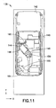
- a slide mechanism 238 in accordance with a third embodiment of the invention.
- the slide mechanism 238 is similar to the slide mechanism 38.
- the slide mechanism 238 comprises a first plate 240, a second plate 242, and a spring actuator 244 as described above with respect to the first embodiment.
- One difference between the slide mechanism 238 and the slide mechanism 38 is the spring configuration.
- the spring members 250 extend between the first plate 240 and the second plate 242 in general curved configuration.
- the first ends 278 of the spring members 250 are rotatably connected to the first plate 240.
- the second ends 280 of the spring members 250 are slidably connected to the slot 260 of the second plate 242.
- the spring members exert spring forces as they bend (as opposed to exerting forces as a result of extension/compression as in the first and second embodiments).
- the spring members 250 may be band springs or leaf springs for example. However, alternate embodiments may provide any suitable type springs. Additionally, it should be noted that the actuator 244 does not require springs or spring members. Instead, the actuator 244 may comprise any suitable resiliently deflectable (or resiliently flexible) member. In the embodiment shown, the spring actuator 244 has three spring members, or resilient members, 250. However, in alternate embodiments, any number of spring members could be provided.
- the "long stroke" and "short stroke” movements of the slide mechanism 238 operate in similar fashion as described above for the first embodiment.
- Fig. 13 illustrates a closed position.
- a user would initiate a "long stroke" movement by pushing the second housing member in a vertical direction as shown by the Y-direction arrow 274. This moves the second plate 242 in the y-direction, wherein the force of the spring members 250 provides similar semi-automatic spring force to that of the first embodiment.
- a user would initiate a "short stroke" movement by pushing the second housing member in a vertical direction opposite to the Y-direction arrow 274. This moves the second plate 242 in the direction opposite to the y-direction arrow 274, wherein the force of the spring members 250 provides similar semi-automatic spring force along the cam profile 266 as that of the first embodiment.
- a slide mechanism 338 in accordance with a fourth embodiment of the invention.
- the slide mechanism 338 is similar to the slide mechanism 238.
- the slide mechanism 338 comprises a first plate 340, a second plate 342, and a spring actuator 344 as described above with respect to the third embodiment.
- One difference between the slide mechanism 338 and the slide mechanism 238 is the orientation of the slot 360 and the cam section 364.
- the slot 360 and the cam section 364 comprise generally angled orientations compared to that of the slot 260 and the cam section 264. These orientations allow for the same general "long stroke” and “short stroke” movements as described above. As illustrated in Fig.
- the spring members 350 extend between the first plate 340 and the second plate 342 in general curved configuration.
- the first ends 378 of the spring members 350 are rotatably connected to the first plate 340.
- the second ends 380 of the spring members 350 are slidably connected to the slot 360 of the second plate 342.
- the spring members exert spring forces as they bend and operate in similar fashion as described above for the third embodiment.
- the disclosed embodiments of the slide mechanism provide novel elements and features for providing the slide movement between the housing members.
- the disclosed slide mechanism provides a suitably sized and shaped spring actuator (which may comprise various configurations), a cam section (which may comprise various cam profile shapes) connected to one of the housing members, and a slot within one of the plates (or slider plates) of the slide mechanism.
- the disclosed elements provide a novel and improved slide mechanism configuration over conventional slide phones and other electronic devices comprising slide mechanisms.
Landscapes
- Engineering & Computer Science (AREA)
- Signal Processing (AREA)
- Telephone Set Structure (AREA)
Claims (14)
- Vorrichtung, umfassend einen Schiebemechanismus, wobei der Schiebemechanismus Folgendes umfasst:eine erste Platte (40);
eine zweite Platte (42), wobei die zweite Platte einen Schlitz (60) umfasst;einen Nockenabschnitt (64), der ein erstes Profil (66) umfasst, wobei der Nockenabschnitt (64) an der ersten Platte (40) befestigt oder einstückig damit ausgebildet ist; und einen elastischen Betätiger (44);wobei ein erstes Verbindungsende (56) des elastischen Betätigers (44) konfiguriert ist, um drehbar mit der ersten Platte (40) verbunden zu werden, und ein zweites Verbindungsende (58) des elastischen Betätigers (44) konfiguriert ist, um mit dem Schlitz (60) der zweiten Platte (42) beweglich verbunden zu werden, und zum Gleiten oder Bewegen oder Rollen entlang des ersten Profils (66) des Nockenabschnitts (64) konfiguriert ist, sodass:wenn die erste Platte (40) in Bezug auf die zweite Platte (42) in eine erste Richtung gegen die Vorspannung des elastischen Betätigers (44) von einer ersten Position zu einer zweiten Position gleitet, während das erste Profil (66) und das zweite Verbindungsende (58) kraft der Vorspannung des elastischen Betätigers (44) betriebswirksam in Eingriff sind, das zweite Verbindungsende (58) des elastischen Betätigers (44) konfiguriert ist, um sich wie folgt zu bewegen: Gleiten entlang des Schlitzes (60); undGleiten oder Rollen entlang des ersten Profils (66) des Nockenabschnitts (64);während die erste Platte (40) in Bezug auf die zweite Platte (42) in eine zweite Richtung entgegen der ersten Richtung von der ersten Position zu einer dritten Position gleitet, wobei die dritte Position eine Position ist, bei der das erste Profil (66) und das zweite Verbindungsende (58) betriebswirksam außer Eingriff gebracht sind:wobei das erste Verbindungsende (56) um seine Drehverbindung zu der ersten Platte (40) gedreht wird;das zweite Verbindungsende (58) innerhalb des Schlitzes (60) gedreht wird; und der elastische Betätiger (44) halbautomatisch durch einen ersten Bewegungsabschnitt gedreht wird, wobei der elastische Betätiger (44) bewegt wird, um die Vorspannung des elastischen Betätigers (44) zu überwinden, und durch einen zweiten Bewegungsabschnitt, der automatisch unter Vorspannung des elastischen Betätigers (44) ist. - Vorrichtung nach Anspruch 1, wobei die zweite Platte (42) konfiguriert ist, um in die erste Richtung zwischen drei Positionen aus der dritten Position zu der ersten Position und dann zu der zweiten Position beweglich zu sein.
- Vorrichtung nach Anspruch 2, wobei die zweite Platte (42) konfiguriert ist, um in die zweite Richtung zwischen drei Positionen aus der zweiten Position zu der ersten Position und dann zu der dritten Position beweglich zu sein.
- Vorrichtung nach einem der vorherigen Ansprüche, wobei der Schiebemechanismus zum automatischen Stoppen der zweiten Platte (42) in der zweiten Position konfiguriert ist, wenn sich die zweite Platte (42) in die erste Richtung in Bezug auf die erste Platte (40) bewegt.
- Vorrichtung nach einem der vorherigen Ansprüche, wobei die zweite Platte (42) konfiguriert ist, um in Bezug auf die erste Platte (40) in mindestens eine Richtung manuell beweglich zu sein.
- Vorrichtung nach einem der vorherigen Ansprüche, wobei der Schiebemechanismus zum halbautomatischen Bewegen der ersten Platte (40) in Bezug auf die zweite Platte (42) von der ersten Position zu der zweiten Position konfiguriert ist.
- Vorrichtung nach einem der vorherigen Ansprüche, wobei der Schlitz (60) eine im Wesentlichen gerade lineare Form aufweist und konfiguriert ist, um im Wesentlichen senkrecht zu der Schiebeachse der ersten Richtung ausgerichtet zu sein.
- Vorrichtung nach einem der vorherigen Ansprüche, wobei die Vorrichtung eine tragbare elektronische Vorrichtung ist.
- Vorrichtung nach einem der vorherigen Ansprüche, wobei die Vorrichtung ein mobiles Telefon, eine Spielevorrichtung oder ein PDA ist.
- Vorrichtung nach Anspruch 1, wobei die zweite Platte (42) konfiguriert ist, um in eine erste Längsrichtung in Bezug auf die erste Platte (40) beweglich zu sein, wenn der elastische Betätiger (44) in eine erste Drehrichtung dreht, und
wobei die zweite Platte (42) konfiguriert ist, um in eine zweite, andere, entgegengesetzte Längsrichtung in Bezug auf die erste Platte (40) beweglich zu sein, wenn der elastische Betätiger (44) in eine zweite andere Drehrichtung dreht. - Vorrichtung nach Anspruch 1, wobei der Winkel zwischen dem elastischen Betätiger (44) in der zweiten Position und in der dritten Position etwa 90 Grad beträgt.
- Vorrichtung nach Anspruch 1, wobei der Winkel zwischen dem elastischen Betätiger (44) in der zweiten Position und in der dritten Position etwa 30 Grad bis etwa 60 Grad beträgt.
- Vorrichtung nach Anspruch 1, wobei das erste Profil eine allgemein winkelige Form aufweist, die sich zwischen zwei Anschlagsbereichen (68, 70) erstreckt.
- Verfahren zur Herstellung einer Vorrichtung, wobei das Verfahren Folgendes umfasst:Bereitstellen einer ersten Platte (40);Bereitstellen einer zweiten Platte (42), wobei die zweite Platte einen Schlitz (60) umfasst;Bereitstellen eines Nockenabschnitts (64), der ein erstes Profil (66) umfasst, wobei der Nockenbereich an der ersten Platte (40) befestigt oder einstückig damit ausgebildet ist; undBereitstellen eines elastischen Betätigers (44),wobei ein erstes Verbindungsende (56) des elastischen Betätigers (44) konfiguriert ist, um drehbar mit der ersten Platte (40) verbunden zu werden,wobei ein zweites Verbindungsende (58) des elastischen Betätigers (44) konfiguriert ist, um beweglich mit dem Schlitz (60) der zweiten Platte (42) verbunden zu werden, und zum Gleiten oder Bewegen oder Rollen entlang des ersten Profils (66) des Nockenabschnitts (64) konfiguriert ist, sodass:während die erste Platte (40) in Bezug auf die zweite Platte (42) in eine erste Richtung gegen die Vorspannung des elastischen Betätigers (44) von einer ersten Position zu einer zweiten Position gleitet, während das erste Profil (66) und das zweite Verbindungsende (58) betriebswirksam kraft der Vorspannung des elastischen Betätigers (44) in Eingriff sind, das zweite Verbindungsende (58) des elastischen Betätigers (44) konfiguriert ist, um sich wie folgt zu bewegen:Gleiten entlang des Schlitzes (60); undGleiten oder Rollen entlang des ersten Profils (66) des Nockenabschnitts (64); und, wenn die erste Platte (40) in Bezug auf die zweite Platte (42) in eine zweite Richtung entgegen der ersten Richtung von der ersten Position zu einer dritten Position gleitet, die dritte Position eine Position ist, bei der das erste Profil (66) und das zweite Verbindungsende (58) betriebswirksam außer Eingriff gebracht sind, wobeidas erste Verbindungsende (56) zum Drehen um seine Drehverbindung mit der ersten Platte (40) konfiguriert ist;das zweite Verbindungsende (58) zum Drehen innerhalb des Schlitzes (60) konfiguriert ist; undder elastische Betätiger (44) zum halbautomatischen Drehen durch einen ersten Bewegungsabschnitt konfiguriert ist, wobei der elastische Betätiger (44) konfiguriert ist, um sich zu bewegen und die Vorspannung des elastischen Betätigers (44) zu überwinden, und ein zweiter Bewegungsabschnitt konfiguriert ist, automatisch unter Vorspannung des elastischen Betätigers (44) zu sein.
Applications Claiming Priority (3)
| Application Number | Priority Date | Filing Date | Title |
|---|---|---|---|
| US93771207P | 2007-06-29 | 2007-06-29 | |
| US11/904,505 US20090005135A1 (en) | 2007-06-29 | 2007-09-26 | Electronic device slide mechanism |
| PCT/IB2008/052553 WO2009004536A2 (en) | 2007-06-29 | 2008-06-25 | Electronic device slide- mechanism adapted to slide in two directions |
Publications (2)
| Publication Number | Publication Date |
|---|---|
| EP2168362A2 EP2168362A2 (de) | 2010-03-31 |
| EP2168362B1 true EP2168362B1 (de) | 2014-08-13 |
Family
ID=40161267
Family Applications (1)
| Application Number | Title | Priority Date | Filing Date |
|---|---|---|---|
| EP08776512.9A Not-in-force EP2168362B1 (de) | 2007-06-29 | 2008-06-25 | Schiebemechanismus für ein elektronisches gerät |
Country Status (6)
| Country | Link |
|---|---|
| US (1) | US20090005135A1 (de) |
| EP (1) | EP2168362B1 (de) |
| KR (1) | KR101124792B1 (de) |
| CN (1) | CN101720549A (de) |
| BR (1) | BRPI0812898A2 (de) |
| WO (1) | WO2009004536A2 (de) |
Families Citing this family (16)
| Publication number | Priority date | Publication date | Assignee | Title |
|---|---|---|---|---|
| US20070180652A1 (en) * | 2006-01-25 | 2007-08-09 | Makoto Miyamoto | Opening and closing device |
| US7853301B2 (en) * | 2006-09-19 | 2010-12-14 | Samsung Electronics Co., Ltd | Sliding module for double sliding-type portable communication terminal |
| CN101460033A (zh) * | 2007-12-11 | 2009-06-17 | 鸿富锦精密工业(深圳)有限公司 | 滑动机构 |
| US8064973B2 (en) * | 2007-12-20 | 2011-11-22 | Nokia Corporation | Electronic device with integrated slide |
| US8224407B2 (en) * | 2009-03-23 | 2012-07-17 | T-Mobile Usa, Inc. | Mobile device having a movable display and associated systems and methods |
| US8391935B2 (en) * | 2009-03-23 | 2013-03-05 | T-Mobile Usa, Inc. | Multifunction mobile device having a movable element, such as a display, and associated functions |
| US8023975B2 (en) * | 2009-03-23 | 2011-09-20 | T-Mobile Usa, Inc. | Secondary status display for mobile device |
| JP2010288248A (ja) * | 2009-05-15 | 2010-12-24 | Fujitsu Ltd | 携帯機器 |
| KR101354217B1 (ko) * | 2009-08-07 | 2014-01-22 | 삼성전자주식회사 | 디스플레이 장치 및 이를 포함하는 복합 엔터테인먼트 기기 |
| JP4781473B1 (ja) * | 2010-03-11 | 2011-09-28 | 三菱製鋼株式会社 | ばねユニット及びスライド機構 |
| US8427829B2 (en) * | 2011-05-06 | 2013-04-23 | Shin Zu Shing Co., Ltd. | Dual directional sliding hinge and portable device |
| CN102858117A (zh) * | 2011-06-30 | 2013-01-02 | 深圳富泰宏精密工业有限公司 | 滑动机构 |
| US8657497B2 (en) * | 2011-07-29 | 2014-02-25 | First Dome Corporation | Slide-rail stabilizing structure of relative sliding device |
| CN103152447B (zh) * | 2011-12-07 | 2016-03-30 | 宏达国际电子股份有限公司 | 手持电子装置 |
| KR20150051773A (ko) * | 2013-11-05 | 2015-05-13 | 엘지전자 주식회사 | 이동 단말기 |
| CN111614817B (zh) | 2020-05-27 | 2021-06-04 | 维沃移动通信有限公司 | 电子设备 |
Family Cites Families (8)
| Publication number | Priority date | Publication date | Assignee | Title |
|---|---|---|---|---|
| JP4252004B2 (ja) | 2004-03-17 | 2009-04-08 | 加藤電機株式会社 | セミオート式のスライド装置 |
| US7289044B2 (en) * | 2004-06-02 | 2007-10-30 | Research In Motion Limited | Handheld electronic device with text disambiguation |
| KR200361808Y1 (ko) * | 2004-06-04 | 2004-09-16 | 조용수 | 슬라이드 방식 휴대폰의 슬라이딩장치 |
| WO2006098590A1 (en) | 2005-03-16 | 2006-09-21 | Jong Chul Choo | Sliding unit and electronic device using it |
| KR20070008363A (ko) * | 2005-07-13 | 2007-01-17 | 추종철 | 다단 슬라이딩 유닛 |
| KR100909474B1 (ko) * | 2005-08-10 | 2009-07-28 | 삼성전자주식회사 | 웨이퍼 결함지수를 사용하여 국부성 불량 모드를 갖는결함성 반도체 웨이퍼의 검출 방법들 및 이에 사용되는장비들 |
| US20070060220A1 (en) * | 2005-09-14 | 2007-03-15 | An-Szu Hsu | Gliding structure for glide-open type mobile phone |
| KR100843584B1 (ko) * | 2007-04-10 | 2008-07-03 | 암페놀피닉스 주식회사 | 휴대전화기용 슬라이드형 개폐장치 |
-
2007
- 2007-09-26 US US11/904,505 patent/US20090005135A1/en not_active Abandoned
-
2008
- 2008-06-25 BR BRPI0812898-7A2A patent/BRPI0812898A2/pt not_active IP Right Cessation
- 2008-06-25 WO PCT/IB2008/052553 patent/WO2009004536A2/en not_active Ceased
- 2008-06-25 EP EP08776512.9A patent/EP2168362B1/de not_active Not-in-force
- 2008-06-25 CN CN200880022815A patent/CN101720549A/zh active Pending
- 2008-06-25 KR KR1020107002063A patent/KR101124792B1/ko not_active Expired - Fee Related
Also Published As
| Publication number | Publication date |
|---|---|
| CN101720549A (zh) | 2010-06-02 |
| KR20100049047A (ko) | 2010-05-11 |
| BRPI0812898A2 (pt) | 2014-12-09 |
| WO2009004536A2 (en) | 2009-01-08 |
| WO2009004536A3 (en) | 2009-02-19 |
| EP2168362A2 (de) | 2010-03-31 |
| KR101124792B1 (ko) | 2012-03-23 |
| US20090005135A1 (en) | 2009-01-01 |
Similar Documents
| Publication | Publication Date | Title |
|---|---|---|
| EP2168362B1 (de) | Schiebemechanismus für ein elektronisches gerät | |
| JP5599226B2 (ja) | 開閉装置 | |
| US8363391B2 (en) | Portable terminal | |
| US20110007465A1 (en) | Open-Close Type Compact Electronic Device | |
| EP2600594B1 (de) | Öffnungs- und schliessvorrichtung | |
| JP2005210649A (ja) | 携帯端末のスライド機構 | |
| US20090168369A1 (en) | Electronic device slide and tilt mechanism | |
| JP2009239657A (ja) | スライド機構及び電子機器 | |
| EP1758343A2 (de) | Scharniervorrichtung und tragbares Endgerät mit dieser Scharniervorrichtung | |
| EP1830542A2 (de) | Federgespannte Schiebevorrichtung für eine tragbare elektronische Vorrichtung | |
| EP2285074B1 (de) | Tragbare elektronische Vorrichtung und Hubmechanismus | |
| EP1786181B1 (de) | Tragbares Telefon mit Schiebemodul zum Schieben der Gehäuser in zwei verschiedene Richtungen | |
| JP2006186201A (ja) | スライド機構及び携帯端末 | |
| KR101094164B1 (ko) | 단말기 | |
| KR100796719B1 (ko) | 슬라이드 힌지 장치 | |
| JP2008092264A (ja) | ヒンジ機構および携帯端末 | |
| US8213169B2 (en) | Sliding hinge and a portable electronic device | |
| KR101756147B1 (ko) | 슬림 틸팅 힌지 및 이를 구비하는 전자기기 | |
| KR101756141B1 (ko) | 슬림 틸팅 힌지 및 이를 구비하는 전자기기 | |
| EP1734725B1 (de) | Tragbares Endgerät mit Verschiebemodul | |
| KR101089238B1 (ko) | 틸팅 가능한 슬라이드 힌지장치 | |
| KR100998877B1 (ko) | 힌지장치 및 이를 이용한 휴대 단말기 | |
| JP5135241B2 (ja) | スライド回転ヒンジ | |
| KR20110078094A (ko) | 슬라이딩형 휴대용 단말기 | |
| KR101235940B1 (ko) | 소형 전자기기의 개폐 장치 및 소형 전자기기 |
Legal Events
| Date | Code | Title | Description |
|---|---|---|---|
| PUAI | Public reference made under article 153(3) epc to a published international application that has entered the european phase |
Free format text: ORIGINAL CODE: 0009012 |
|
| 17P | Request for examination filed |
Effective date: 20100113 |
|
| AK | Designated contracting states |
Kind code of ref document: A2 Designated state(s): AT BE BG CH CY CZ DE DK EE ES FI FR GB GR HR HU IE IS IT LI LT LU LV MC MT NL NO PL PT RO SE SI SK TR |
|
| AX | Request for extension of the european patent |
Extension state: AL BA MK RS |
|
| 17Q | First examination report despatched |
Effective date: 20100419 |
|
| DAX | Request for extension of the european patent (deleted) | ||
| GRAP | Despatch of communication of intention to grant a patent |
Free format text: ORIGINAL CODE: EPIDOSNIGR1 |
|
| INTG | Intention to grant announced |
Effective date: 20140221 |
|
| RAP1 | Party data changed (applicant data changed or rights of an application transferred) |
Owner name: NOKIA CORPORATION |
|
| GRAS | Grant fee paid |
Free format text: ORIGINAL CODE: EPIDOSNIGR3 |
|
| GRAA | (expected) grant |
Free format text: ORIGINAL CODE: 0009210 |
|
| AK | Designated contracting states |
Kind code of ref document: B1 Designated state(s): AT BE BG CH CY CZ DE DK EE ES FI FR GB GR HR HU IE IS IT LI LT LU LV MC MT NL NO PL PT RO SE SI SK TR |
|
| RAP1 | Party data changed (applicant data changed or rights of an application transferred) |
Owner name: NOKIA CORPORATION |
|
| REG | Reference to a national code |
Ref country code: GB Ref legal event code: FG4D |
|
| REG | Reference to a national code |
Ref country code: AT Ref legal event code: REF Ref document number: 682803 Country of ref document: AT Kind code of ref document: T Effective date: 20140815 Ref country code: CH Ref legal event code: EP |
|
| REG | Reference to a national code |
Ref country code: IE Ref legal event code: FG4D |
|
| REG | Reference to a national code |
Ref country code: DE Ref legal event code: R096 Ref document number: 602008033856 Country of ref document: DE Effective date: 20140925 |
|
| REG | Reference to a national code |
Ref country code: NL Ref legal event code: VDEP Effective date: 20140813 |
|
| REG | Reference to a national code |
Ref country code: AT Ref legal event code: MK05 Ref document number: 682803 Country of ref document: AT Kind code of ref document: T Effective date: 20140813 |
|
| REG | Reference to a national code |
Ref country code: LT Ref legal event code: MG4D |
|
| PG25 | Lapsed in a contracting state [announced via postgrant information from national office to epo] |
Ref country code: LT Free format text: LAPSE BECAUSE OF FAILURE TO SUBMIT A TRANSLATION OF THE DESCRIPTION OR TO PAY THE FEE WITHIN THE PRESCRIBED TIME-LIMIT Effective date: 20140813 Ref country code: FI Free format text: LAPSE BECAUSE OF FAILURE TO SUBMIT A TRANSLATION OF THE DESCRIPTION OR TO PAY THE FEE WITHIN THE PRESCRIBED TIME-LIMIT Effective date: 20140813 Ref country code: SE Free format text: LAPSE BECAUSE OF FAILURE TO SUBMIT A TRANSLATION OF THE DESCRIPTION OR TO PAY THE FEE WITHIN THE PRESCRIBED TIME-LIMIT Effective date: 20140813 Ref country code: PT Free format text: LAPSE BECAUSE OF FAILURE TO SUBMIT A TRANSLATION OF THE DESCRIPTION OR TO PAY THE FEE WITHIN THE PRESCRIBED TIME-LIMIT Effective date: 20141215 Ref country code: BG Free format text: LAPSE BECAUSE OF FAILURE TO SUBMIT A TRANSLATION OF THE DESCRIPTION OR TO PAY THE FEE WITHIN THE PRESCRIBED TIME-LIMIT Effective date: 20141113 Ref country code: NO Free format text: LAPSE BECAUSE OF FAILURE TO SUBMIT A TRANSLATION OF THE DESCRIPTION OR TO PAY THE FEE WITHIN THE PRESCRIBED TIME-LIMIT Effective date: 20141113 Ref country code: GR Free format text: LAPSE BECAUSE OF FAILURE TO SUBMIT A TRANSLATION OF THE DESCRIPTION OR TO PAY THE FEE WITHIN THE PRESCRIBED TIME-LIMIT Effective date: 20141114 Ref country code: ES Free format text: LAPSE BECAUSE OF FAILURE TO SUBMIT A TRANSLATION OF THE DESCRIPTION OR TO PAY THE FEE WITHIN THE PRESCRIBED TIME-LIMIT Effective date: 20140813 |
|
| PG25 | Lapsed in a contracting state [announced via postgrant information from national office to epo] |
Ref country code: LV Free format text: LAPSE BECAUSE OF FAILURE TO SUBMIT A TRANSLATION OF THE DESCRIPTION OR TO PAY THE FEE WITHIN THE PRESCRIBED TIME-LIMIT Effective date: 20140813 Ref country code: IS Free format text: LAPSE BECAUSE OF FAILURE TO SUBMIT A TRANSLATION OF THE DESCRIPTION OR TO PAY THE FEE WITHIN THE PRESCRIBED TIME-LIMIT Effective date: 20141213 Ref country code: CY Free format text: LAPSE BECAUSE OF FAILURE TO SUBMIT A TRANSLATION OF THE DESCRIPTION OR TO PAY THE FEE WITHIN THE PRESCRIBED TIME-LIMIT Effective date: 20140813 Ref country code: HR Free format text: LAPSE BECAUSE OF FAILURE TO SUBMIT A TRANSLATION OF THE DESCRIPTION OR TO PAY THE FEE WITHIN THE PRESCRIBED TIME-LIMIT Effective date: 20140813 Ref country code: AT Free format text: LAPSE BECAUSE OF FAILURE TO SUBMIT A TRANSLATION OF THE DESCRIPTION OR TO PAY THE FEE WITHIN THE PRESCRIBED TIME-LIMIT Effective date: 20140813 |
|
| PG25 | Lapsed in a contracting state [announced via postgrant information from national office to epo] |
Ref country code: NL Free format text: LAPSE BECAUSE OF FAILURE TO SUBMIT A TRANSLATION OF THE DESCRIPTION OR TO PAY THE FEE WITHIN THE PRESCRIBED TIME-LIMIT Effective date: 20140813 |
|
| PG25 | Lapsed in a contracting state [announced via postgrant information from national office to epo] |
Ref country code: DK Free format text: LAPSE BECAUSE OF FAILURE TO SUBMIT A TRANSLATION OF THE DESCRIPTION OR TO PAY THE FEE WITHIN THE PRESCRIBED TIME-LIMIT Effective date: 20140813 Ref country code: EE Free format text: LAPSE BECAUSE OF FAILURE TO SUBMIT A TRANSLATION OF THE DESCRIPTION OR TO PAY THE FEE WITHIN THE PRESCRIBED TIME-LIMIT Effective date: 20140813 Ref country code: IT Free format text: LAPSE BECAUSE OF FAILURE TO SUBMIT A TRANSLATION OF THE DESCRIPTION OR TO PAY THE FEE WITHIN THE PRESCRIBED TIME-LIMIT Effective date: 20140813 Ref country code: RO Free format text: LAPSE BECAUSE OF FAILURE TO SUBMIT A TRANSLATION OF THE DESCRIPTION OR TO PAY THE FEE WITHIN THE PRESCRIBED TIME-LIMIT Effective date: 20140813 Ref country code: CZ Free format text: LAPSE BECAUSE OF FAILURE TO SUBMIT A TRANSLATION OF THE DESCRIPTION OR TO PAY THE FEE WITHIN THE PRESCRIBED TIME-LIMIT Effective date: 20140813 Ref country code: SK Free format text: LAPSE BECAUSE OF FAILURE TO SUBMIT A TRANSLATION OF THE DESCRIPTION OR TO PAY THE FEE WITHIN THE PRESCRIBED TIME-LIMIT Effective date: 20140813 |
|
| REG | Reference to a national code |
Ref country code: DE Ref legal event code: R097 Ref document number: 602008033856 Country of ref document: DE |
|
| PG25 | Lapsed in a contracting state [announced via postgrant information from national office to epo] |
Ref country code: PL Free format text: LAPSE BECAUSE OF FAILURE TO SUBMIT A TRANSLATION OF THE DESCRIPTION OR TO PAY THE FEE WITHIN THE PRESCRIBED TIME-LIMIT Effective date: 20140813 |
|
| PLBE | No opposition filed within time limit |
Free format text: ORIGINAL CODE: 0009261 |
|
| STAA | Information on the status of an ep patent application or granted ep patent |
Free format text: STATUS: NO OPPOSITION FILED WITHIN TIME LIMIT |
|
| 26N | No opposition filed |
Effective date: 20150515 |
|
| REG | Reference to a national code |
Ref country code: DE Ref legal event code: R081 Ref document number: 602008033856 Country of ref document: DE Owner name: NOKIA TECHNOLOGIES OY, FI Free format text: FORMER OWNER: NOKIA CORPORATION, ESPOO, FI Ref country code: DE Ref legal event code: R081 Ref document number: 602008033856 Country of ref document: DE Owner name: NOKIA TECHNOLOGIES OY, FI Free format text: FORMER OWNER: NOKIA CORPORATION, 02610 ESPOO, FI |
|
| PG25 | Lapsed in a contracting state [announced via postgrant information from national office to epo] |
Ref country code: SI Free format text: LAPSE BECAUSE OF FAILURE TO SUBMIT A TRANSLATION OF THE DESCRIPTION OR TO PAY THE FEE WITHIN THE PRESCRIBED TIME-LIMIT Effective date: 20140813 |
|
| PG25 | Lapsed in a contracting state [announced via postgrant information from national office to epo] |
Ref country code: MC Free format text: LAPSE BECAUSE OF FAILURE TO SUBMIT A TRANSLATION OF THE DESCRIPTION OR TO PAY THE FEE WITHIN THE PRESCRIBED TIME-LIMIT Effective date: 20140813 |
|
| REG | Reference to a national code |
Ref country code: CH Ref legal event code: PL |
|
| GBPC | Gb: european patent ceased through non-payment of renewal fee |
Effective date: 20150625 |
|
| PG25 | Lapsed in a contracting state [announced via postgrant information from national office to epo] |
Ref country code: LU Free format text: LAPSE BECAUSE OF FAILURE TO SUBMIT A TRANSLATION OF THE DESCRIPTION OR TO PAY THE FEE WITHIN THE PRESCRIBED TIME-LIMIT Effective date: 20150625 |
|
| REG | Reference to a national code |
Ref country code: IE Ref legal event code: MM4A |
|
| REG | Reference to a national code |
Ref country code: FR Ref legal event code: ST Effective date: 20160229 |
|
| PG25 | Lapsed in a contracting state [announced via postgrant information from national office to epo] |
Ref country code: IE Free format text: LAPSE BECAUSE OF NON-PAYMENT OF DUE FEES Effective date: 20150625 Ref country code: CH Free format text: LAPSE BECAUSE OF NON-PAYMENT OF DUE FEES Effective date: 20150630 Ref country code: LI Free format text: LAPSE BECAUSE OF NON-PAYMENT OF DUE FEES Effective date: 20150630 Ref country code: GB Free format text: LAPSE BECAUSE OF NON-PAYMENT OF DUE FEES Effective date: 20150625 |
|
| PG25 | Lapsed in a contracting state [announced via postgrant information from national office to epo] |
Ref country code: FR Free format text: LAPSE BECAUSE OF NON-PAYMENT OF DUE FEES Effective date: 20150630 |
|
| PG25 | Lapsed in a contracting state [announced via postgrant information from national office to epo] |
Ref country code: BE Free format text: LAPSE BECAUSE OF FAILURE TO SUBMIT A TRANSLATION OF THE DESCRIPTION OR TO PAY THE FEE WITHIN THE PRESCRIBED TIME-LIMIT Effective date: 20140813 |
|
| PG25 | Lapsed in a contracting state [announced via postgrant information from national office to epo] |
Ref country code: MT Free format text: LAPSE BECAUSE OF FAILURE TO SUBMIT A TRANSLATION OF THE DESCRIPTION OR TO PAY THE FEE WITHIN THE PRESCRIBED TIME-LIMIT Effective date: 20140813 |
|
| PG25 | Lapsed in a contracting state [announced via postgrant information from national office to epo] |
Ref country code: HU Free format text: LAPSE BECAUSE OF FAILURE TO SUBMIT A TRANSLATION OF THE DESCRIPTION OR TO PAY THE FEE WITHIN THE PRESCRIBED TIME-LIMIT; INVALID AB INITIO Effective date: 20080625 |
|
| PG25 | Lapsed in a contracting state [announced via postgrant information from national office to epo] |
Ref country code: TR Free format text: LAPSE BECAUSE OF FAILURE TO SUBMIT A TRANSLATION OF THE DESCRIPTION OR TO PAY THE FEE WITHIN THE PRESCRIBED TIME-LIMIT Effective date: 20140813 |
|
| PGFP | Annual fee paid to national office [announced via postgrant information from national office to epo] |
Ref country code: DE Payment date: 20180612 Year of fee payment: 11 |
|
| REG | Reference to a national code |
Ref country code: DE Ref legal event code: R119 Ref document number: 602008033856 Country of ref document: DE |
|
| PG25 | Lapsed in a contracting state [announced via postgrant information from national office to epo] |
Ref country code: DE Free format text: LAPSE BECAUSE OF NON-PAYMENT OF DUE FEES Effective date: 20200101 |