EP2168362B1 - Electronic device slide mechanism - Google Patents
Electronic device slide mechanism Download PDFInfo
- Publication number
- EP2168362B1 EP2168362B1 EP08776512.9A EP08776512A EP2168362B1 EP 2168362 B1 EP2168362 B1 EP 2168362B1 EP 08776512 A EP08776512 A EP 08776512A EP 2168362 B1 EP2168362 B1 EP 2168362B1
- Authority
- EP
- European Patent Office
- Prior art keywords
- plate
- resilient actuator
- connecting end
- actuator
- profile
- Prior art date
- Legal status (The legal status is an assumption and is not a legal conclusion. Google has not performed a legal analysis and makes no representation as to the accuracy of the status listed.)
- Not-in-force
Links
Images


Classifications
-
- H—ELECTRICITY
- H04—ELECTRIC COMMUNICATION TECHNIQUE
- H04M—TELEPHONIC COMMUNICATION
- H04M1/00—Substation equipment, e.g. for use by subscribers
- H04M1/02—Constructional features of telephone sets
- H04M1/0202—Portable telephone sets, e.g. cordless phones, mobile phones or bar type handsets
- H04M1/0206—Portable telephones comprising a plurality of mechanically joined movable body parts, e.g. hinged housings
- H04M1/0208—Portable telephones comprising a plurality of mechanically joined movable body parts, e.g. hinged housings characterized by the relative motions of the body parts
- H04M1/0235—Slidable or telescopic telephones, i.e. with a relative translation movement of the body parts; Telephones using a combination of translation and other relative motions of the body parts
- H04M1/0237—Sliding mechanism with one degree of freedom
-
- H—ELECTRICITY
- H04—ELECTRIC COMMUNICATION TECHNIQUE
- H04M—TELEPHONIC COMMUNICATION
- H04M1/00—Substation equipment, e.g. for use by subscribers
- H04M1/02—Constructional features of telephone sets
- H04M1/0202—Portable telephone sets, e.g. cordless phones, mobile phones or bar type handsets
- H04M1/0206—Portable telephones comprising a plurality of mechanically joined movable body parts, e.g. hinged housings
- H04M1/0241—Portable telephones comprising a plurality of mechanically joined movable body parts, e.g. hinged housings using relative motion of the body parts to change the operational status of the telephone set, e.g. switching on/off, answering incoming call
- H04M1/0245—Portable telephones comprising a plurality of mechanically joined movable body parts, e.g. hinged housings using relative motion of the body parts to change the operational status of the telephone set, e.g. switching on/off, answering incoming call using open/close detection
-
- H—ELECTRICITY
- H04—ELECTRIC COMMUNICATION TECHNIQUE
- H04M—TELEPHONIC COMMUNICATION
- H04M1/00—Substation equipment, e.g. for use by subscribers
- H04M1/02—Constructional features of telephone sets
- H04M1/0202—Portable telephone sets, e.g. cordless phones, mobile phones or bar type handsets
- H04M1/026—Details of the structure or mounting of specific components
- H04M1/0264—Details of the structure or mounting of specific components for a camera module assembly
Definitions
- the invention relates to an electronic device and, more particularly, to a slide mechanism for an electronic device.
- WO 2006098590 relates to a sliding unit and an electronic device using the same, which can connect, in sliding manner, a transmitting part with a receiving part of a cellular phone that opens/closes the transmitting part and the receiving part in sliding manner, by connecting each section with the transmitting part and the receiving part of the sliding-type cellular phone.
- Nokia “N95-1: Get started” (www.nokia.com, retrieved from internet on 10 August 2010: URL: http://nds1.nokia.com/phones/files/guides/Nokia_N95-1_release2_GS_en.pdf ) relates to a mobile phone which has slidable housings.
- JP 2005269070 describes a semiautomatic slider unit, for sliding a first case and a second case relatively in one direction, comprising a cam member fixed to the side of any one of the first and second cases, a rotating member fixed rotatably to the cam member and supported rotatably in an elongated guide hole provided on the side of the other of the first and second cases, and a slider provided between the rotating member and the cam member while butting against the cam part of the cam member at the forward end and being urged to slide in one direction.
- the prior art does not provide for a second connecting end of the resilient actuator configured to be movably connected to a slot of a second plate and configured to slide or move or roll along a first profile of a cam section, such that:
- the invention is directed to an apparatus and a method as set out in the independent claims.
- Advantageous embodiments are set out in the dependent claims.
- a portable electronic device in accordance with one aspect described herein, includes a housing, electronic circuitry, and a slide mechanism.
- the housing includes a first housing member and a second housing member.
- the electronic circuitry is mounted in the housing.
- the slide mechanism is between the first housing member and the second housing member.
- the slide mechanism includes a cam section and an actuator.
- the cam section is configured to be connected to a first housing member.
- the actuator is configured to contact a first side of the cam section.
- a first end of the actuator is configured to be movably connected to the first housing member.
- a second end of the actuator is configured to be movably connected to a second housing member.
- the second housing member is configured to be movable in a first direction when the actuator moves in a direction away from the cam section.
- the second housing member is configured to be movable in a second direction when the actuator moves along the first side of the cam section.
- a portable electronic device in accordance with another aspect described herein.
- the portable electronic device includes a housing, electronic circuitry, and a slide connection.
- the housing includes a first housing member and a second housing member.
- the electronic circuitry is mounted in the housing.
- the slide connection is adapted to slidably connect the second housing member to the first housing member.
- the slide connection is adapted to semi-automatically slide when an end of at least one of the housing members is moved above a top end of the portable electronic device.
- the slide connection is adapted to slide when an opposite end of the at least one housing member is moved below a bottom end of the portable electronic device.
- a portable electronic device in accordance with another aspect described herein.
- the portable electronic device includes a housing, electronic circuitry, and an actuator.
- the housing includes a first housing member and a second housing member.
- the electronic circuitry is mounted in the housing.
- the actuator has a first end and a second end. The first end is rotatably connected to the first housing member. The second end is slidably connected to the second housing member.
- the second housing member is configured to be movable in a first longitudinal direction relative to the first housing member when the actuator rotates in a first direction of rotation.
- the second housing member is configured to be movable in a second different longitudinal direction relative to the first housing member when the actuator rotates in a second different direction of rotation.
- a method of manufacturing a portable electronic device is disclosed.
- a first housing member is provided.
- a cam section is connected to the first housing member.
- a first end of an actuator is rotatably connected to the first housing member.
- a second end of the actuator is slidably connected to a second housing member. The second end is configured to contact a side of the cam section.
- Electronic circuitry is installed within at least one of the housing members.
- FIG. 1 there is shown a perspective view of a portable electronic device 10 incorporating features of the invention.
- a portable electronic device 10 incorporating features of the invention.
- the invention will be described with reference to the exemplary embodiments shown in the drawings, it should be understood that the invention can be embodied in many alternate forms of embodiments.
- any suitable size, shape or type of elements or materials could be used.
- the device 10 is a multi function portable electronic device.
- features of the exemplary embodiment of this invention could be used in any suitable type of hand-held portable electronic device such as a mobile phone, a gaming device, a music player, or a PDA, for example.
- the device 10 can include features or applications such as a camera, a music player, a game player, or an internet browser, for example.
- the device 10 generally comprises a housing 12 and electronic circuitry 14.
- the electronic circuitry 14 includes, for example, a transceiver, a controller such as a microprocessor, a memory, etc.
- the housing 12 includes a first housing member 16 and a second housing member 18. It should be noted that in alternate embodiments, more than two housing members could be provided.
- the second housing member 18 is movably connected to the first housing member 16. More specifically, the second housing member 18 is slidably mounted to the first housing member 16 between a closed position as shown in Figs. 1 and 2 , a first open position as shown in Fig. 3 , and a second open position as shown in Fig. 4 .
- the first housing member 16 comprises a first user input region 20 at a first end 22 of the first housing member 16.
- the first user input region 20 may be a keyboard, a keypad, or a keymat, for example. However, it should be noted that alternate embodiments may provide any suitable type of user input region.
- the first user input region 20 is visible and accessible when the device 10 is in the first open position. In this first open position, a first end 23 of the second housing member 18 is above a top end 25 of the device 10.
- the first housing member 16 comprises a second user input region 24 at a second end 26 of the first housing member 16.
- the second user input region 24 may comprise control buttons or a keypad, for example. However, it should be noted that alternate embodiments may provide any suitable type of user input region.
- the second user input region 24 is visible and accessible when the device 10 is in the second open position. In this second open position, a second end 27 of the second housing member 18 is above a bottom end 29 of the device 10.
- the second housing member 18 generally comprises a display screen 28 and a third user input region 30.
- the third user input region 30 may comprise a multi-function key and control keys, for example. However, it should be noted that alternate embodiments may provide any suitable type of user input region.
- the second housing member may comprise a camera 32, a light sensor 34, and an ear piece 36, for example.
- the slide mechanism 38 in accordance with a first embodiment of the invention.
- the slide mechanism (or slide connection) 38 comprises a first plate 40, a second plate 42, and a spring actuator 44.
- the first plate 40 is configured to be connected to the first housing member 16.
- the second plate 42 is configured to be connected to the second housing member 18.
- the plates 40, 42 may be connected to the housing members 16, 18 by any suitable means. It should be noted that in an alternate embodiment, the plates 40, 42 may be integrally formed with the housing members 16, 18.
- the slide mechanism 38 is between the first plate 40 and the second plate 42.
- the second plate 42 (and the connected second housing member 18) is slidably mounted to the first plate 40 (and the first housing member 16) between the closed position as shown in Fig. 5 (and also shown in Figs. 1-2 ), the first open position as shown in Fig. 7 (and also shown in Fig. 3 ), and the second open position as shown in Fig. 8 (and also shown in Fig. 4 ).
- the spring actuator 44 is disposed between the first plate 40 and the second plate 42.
- the spring actuator comprises a first spring frame member 46, a second spring frame member 48, and spring members 50.
- the spring members 50 may be coil springs for example. However, alternate embodiments may provide any suitable type springs. Additionally, it should be noted that the actuator 44 does not require springs or spring members. Instead, the actuator 44 may comprise any suitable resiliently deflectable (or resiliently flexible) members. In the embodiment shown, the spring actuator 44 has two spring members, or resilient members, 50. However, in alternate embodiments, any number of spring members could be provided. Opposite ends of the spring members 50 are connected to mount ends 52, 54 of the spring frame members 46, 48.
- the first spring frame member 46 and the second spring frame member 48 are slidably connected to each other such that a spring force of the spring members 50 may be exerted on the mount ends 52, 54.
- a connecting end 56 of the first spring frame member 46 is rotatably connected to the first plate 40.
- the connecting end 56 may be attached to first plate, or first module, 40 by riveting or any other suitable method that allows rotational movement.
- a connecting end 58 of the second spring frame member 48 is slidably connected to a slot 60 of the second plate 42.
- the connecting end 58 may be attached to the second plate, or second module, 42 by riveting (see rivet 62 in Fig. 6 ) or any other suitable method that allows rotational movement, linear sliding, and moving in the slot 60.
- the slots 60 may comprise a slot having any suitable shape or orientation.
- the slide mechanism 38 further comprises a cam section 64 attached to the first plate 40.
- the cam section 40 may be attached to the plate 40 by any suitable means. However, alternate embodiments may provide for a cam section integrally formed with the first plate.
- the cam section 64 comprises a first side, or first profile, 66.
- the first side 66 comprises a generally angled shape extending between two stop regions 68, 70.
- alternate embodiments may comprise a cam section having any suitable profile shape for contacting the spring actuator 44.
- the connecting end 58 of the second spring frame member 48 is configured to slide or move along the first side 66 of the cam section 64. Any suitable configuration allowing for the connecting end 58 to slide or roll between the stop regions 68, 70 of the first side may be provided, such as a roller 72 for example.
- the slide mechanism 38 allows for semi-automatic movement of the housing members 16, 18.
- a user would initiate a "long stroke" movement by pushing the second housing member in a vertical direction as shown by the Y-direction arrow 74. This moves the second plate 42 in the Y-direction, and moves the spring frame members 46, 48 against the force of the spring members 50.
- the connecting end 56 rotates about the connection to the plate 40, the connecting end 58 rotates within the slot 60, and the sprint actuator 44 generally rotates in a clockwise fashion (wherein the connecting end 58 moves in a first direction of rotation) between the positions of Fig. 5 and Fig. 7 .
- the mount ends 52, 54 reach their greatest separation distance and then move towards each other with assistance of the spring force.
- the spring assisted relative movement of the spring frame members 46, 48 provides the semi-automatic movement between the housing members 16, 18.
- the semi-automatic movement comprises a first portion of the movement which is manual (by the user overcoming the force of the springs) and a second portion of the movement which is automatic by the force of the springs acting in the desired direction.
- first housing member being offset from the second housing member in the longitudinal direction (Y-direction 74) and allows access to the first input region 20.
- initial manual movement may be performed by hand or by a trigger for example.
- the offset or opening length may be any suitable distance such as 30 mm for example. This opening length or "long stroke" can vary in different embodiments.
- a user would initiate a "short stroke" movement by pushing the second housing member in a vertical direction opposite to the Y-direction arrow 74. This moves the second plate 42 in the direction opposite to the y-direction, and moves the spring frame members 46, 48 against the force of the spring members 50.
- This movement is provided as the connecting end 56 rotates about the connection to the plate 40, the connecting end 58 rotates along the length of the slot 60, and the sprint actuator 44 generally rotates in a counterclockwise fashion (wherein the connecting end 58 moves in a second different direction of rotation) between the positions of Fig. 5 and Fig. 8 .
- the mount ends 52, 54 Approximately half way through the movement, the mount ends 52, 54, reach their greatest separation distance and then move towards each other with assistance of the spring force.
- the spring assisted relative movement of the spring frame members 46, 48 provides the semi-automatic movement between the housing members 16, 18.
- the semi-automatic movement comprises a first portion of the movement which is manual (by the user overcoming the force of the springs) and a second portion of the movement which is automatic by the force of the springs acting in the desired direction.
- the initial manual movement may be performed by hand or by a trigger for example.
- This "short stroke” movement moves the connecting end 58 from the first stop region 68 of the cam section 64 to the second stop region 70 (direction 76) of the cam section 64.
- the offset or opening length may be any suitable distance such as 12mm for example. This opening length or "short stroke” can vary in different embodiments.
- the opposite movements are carried out in a similar fashion as the movements described above.
- the movement stops at a middle locking position automatically.
- the "stop" movement is created by a certain combination of spring force of the spring members 50, angle of the slot 60, and the cam profile 66.
- the "short stoke” movement may not be a semi-automatic movement due to certain combinations of the spring members 50, the cam profile 66, and the angle of the slot 60 or because the short stroke is much longer than about 12mm.
- the first portion and/or the second portion of the "short stroke” movement may comprise a manual movement.
- the portion of the movement returning the housing members 16, 18 to the middle locking position may comprise a manual movement.
- the invention relates to a semi-automatic dual slide mechanism for a device 10.
- a semi-automatic dual slide mechanism for a device 10.
- One possible use would be for opening and closing a slide phone, thus opening and closing the first user input region 20, such as an ITU keymat for example, wherein the rotation of the spring actuator 44 away from the cam section 64 is used to create semi-automatic movement.
- Another possible use would be for opening and closing a slide phone, thus opening and closing the second user input region 24 wherein the rotation of the spring actuator 44 along the cam profile 66 is used to create the semi-automatic movement.
- multi-movements (more than two movements) of the housing members 16, 18 to same direction or different directions could also be provided by the disclosed slide mechanism.
- the disclosed slide mechanism provides slide movement in the vertical/longitudinal direction (Y-direction 74). However, it should be noted that the slide mechanism may provide additional slide movements in any suitable direction. Additionally, the disclosed slide mechanism provides the novelty and advantage of combining the two spring assisted sliding principles of the turning spring principle (or "long stroke” movement) and the cam/spring principle (or “short stroke” movement) while using the same spring actuator.
- the spring force typically is about 90 degrees relative to the sliding direction. Whereas in the invention the spring force turns between about 30 to about 60 degrees in the cam assisted part of the movement.
- the whole sliding mechanism has the advantage of the turning spring principle where the spring force mainly works in or against the sliding direction (but which has only two end positions). And the cam/spring principle which has multiple end/rest positions (but where the spring force needs to be turned about 90 degrees by help of the cam and therefore is a less efficient and less comfortable.)
- the disclosed slide mechanism provides excellent semi-auto function in opening and closing of slide phone when opening and closing ITU keymat.
- the movement down or “short stroke” movement
- actuator will follow the profile by sliding or with roller.
- revealing and hiding ITU-keys with help of excellent semi-auto function is big advantage. This may result in commercial value wherein disclosed slide mechanism may be used across all suitable applications and competitors (including all mobile phone manufacturers) realize the benefits by this concept.
- a slide mechanism 138 in accordance with a second embodiment of the invention.
- the slide mechanism 138 is similar to the slide mechanism 38.
- the slide mechanism 138 comprises a first plate 140, a second plate 142, and a spring actuator 144 as described above with respect to the first embodiment.
- One difference between the slide mechanism 138 and the slide mechanism 38 is the location and shape of the cam section 164.
- the cam section 164 is adjacent to a lateral side of the first plate 140.
- the profile 166 of the cam section 164 comprises a non-linear shape.
- the slot 160 comprises an angled configuration.
- the spring actuator 144 comprises one spring member 150.
- the spring member 150 may be a coil spring for example. However, alternate embodiments may provide any suitable type spring. Additionally, it should be noted that the actuator 144 does not require a spring or a spring member. Instead, the actuator 144 may comprise any suitable resiliently deflectable (or resiliently flexible) member. In the embodiment shown, the spring actuator 144 has one spring member, or resilient member, 150. However, in alternate embodiments, any number of spring members could be provided.
- Figs. 9 and 10 illustrate a closed position.
- a user would initiate a "long stroke" movement by pushing the second housing member in a vertical direction as shown by the Y-direction arrow 174. This moves the second plate 142 in the y-direction, and moves the spring frame members 146, 148 against the force of the spring member 150.
- a user would initiate a "short stroke" movement by pushing the second housing member in a vertical direction opposite to the Y-direction arrow 174. This moves the second plate 142 in the direction opposite to the y-direction arrow 174, and moves the spring frame members 146, 148 against the force of the spring member 150.
- a slide mechanism 238 in accordance with a third embodiment of the invention.
- the slide mechanism 238 is similar to the slide mechanism 38.
- the slide mechanism 238 comprises a first plate 240, a second plate 242, and a spring actuator 244 as described above with respect to the first embodiment.
- One difference between the slide mechanism 238 and the slide mechanism 38 is the spring configuration.
- the spring members 250 extend between the first plate 240 and the second plate 242 in general curved configuration.
- the first ends 278 of the spring members 250 are rotatably connected to the first plate 240.
- the second ends 280 of the spring members 250 are slidably connected to the slot 260 of the second plate 242.
- the spring members exert spring forces as they bend (as opposed to exerting forces as a result of extension/compression as in the first and second embodiments).
- the spring members 250 may be band springs or leaf springs for example. However, alternate embodiments may provide any suitable type springs. Additionally, it should be noted that the actuator 244 does not require springs or spring members. Instead, the actuator 244 may comprise any suitable resiliently deflectable (or resiliently flexible) member. In the embodiment shown, the spring actuator 244 has three spring members, or resilient members, 250. However, in alternate embodiments, any number of spring members could be provided.
- the "long stroke" and "short stroke” movements of the slide mechanism 238 operate in similar fashion as described above for the first embodiment.
- Fig. 13 illustrates a closed position.
- a user would initiate a "long stroke" movement by pushing the second housing member in a vertical direction as shown by the Y-direction arrow 274. This moves the second plate 242 in the y-direction, wherein the force of the spring members 250 provides similar semi-automatic spring force to that of the first embodiment.
- a user would initiate a "short stroke" movement by pushing the second housing member in a vertical direction opposite to the Y-direction arrow 274. This moves the second plate 242 in the direction opposite to the y-direction arrow 274, wherein the force of the spring members 250 provides similar semi-automatic spring force along the cam profile 266 as that of the first embodiment.
- a slide mechanism 338 in accordance with a fourth embodiment of the invention.
- the slide mechanism 338 is similar to the slide mechanism 238.
- the slide mechanism 338 comprises a first plate 340, a second plate 342, and a spring actuator 344 as described above with respect to the third embodiment.
- One difference between the slide mechanism 338 and the slide mechanism 238 is the orientation of the slot 360 and the cam section 364.
- the slot 360 and the cam section 364 comprise generally angled orientations compared to that of the slot 260 and the cam section 264. These orientations allow for the same general "long stroke” and “short stroke” movements as described above. As illustrated in Fig.
- the spring members 350 extend between the first plate 340 and the second plate 342 in general curved configuration.
- the first ends 378 of the spring members 350 are rotatably connected to the first plate 340.
- the second ends 380 of the spring members 350 are slidably connected to the slot 360 of the second plate 342.
- the spring members exert spring forces as they bend and operate in similar fashion as described above for the third embodiment.
- the disclosed embodiments of the slide mechanism provide novel elements and features for providing the slide movement between the housing members.
- the disclosed slide mechanism provides a suitably sized and shaped spring actuator (which may comprise various configurations), a cam section (which may comprise various cam profile shapes) connected to one of the housing members, and a slot within one of the plates (or slider plates) of the slide mechanism.
- the disclosed elements provide a novel and improved slide mechanism configuration over conventional slide phones and other electronic devices comprising slide mechanisms.
Description
- The invention relates to an electronic device and, more particularly, to a slide mechanism for an electronic device.
- As electronic devices continue to become more sophisticated, these devices provide an increasing amount of functionality by including such applications as, for example, a mobile phone, digital camera, video camera, navigation system, gaming capabilities, and internet browser applications. Many of these devices with increased functionality have more than one configuration. Electronic devices having slidable housing members, such as a slide phone for example, proving multiple configurations are known in the art. As consumers demand increased functionality from electronic devices, there is a need to provide improved devices having increased capabilities while maintaining robust and reliable product configurations. Accordingly, there is a desire to provide an improved electronic device slide mechanism.
-
WO 2006098590 relates to a sliding unit and an electronic device using the same, which can connect, in sliding manner, a transmitting part with a receiving part of a cellular phone that opens/closes the transmitting part and the receiving part in sliding manner, by connecting each section with the transmitting part and the receiving part of the sliding-type cellular phone. - Nokia "N95-1: Get started" (www.nokia.com, retrieved from internet on 10 August 2010: URL: http://nds1.nokia.com/phones/files/guides/Nokia_N95-1_release2_GS_en.pdf) relates to a mobile phone which has slidable housings.
-
JP 2005269070 - The prior art does not provide for a second connecting end of the resilient actuator configured to be movably connected to a slot of a second plate and configured to slide or move or roll along a first profile of a cam section, such that:
- as the first plate (40) is slid with respect to the second plate (42) in a first direction against the bias of the resilient actuator (44) from a first position to a second position, during which the first profile (66) and the second connecting end (58) are operably engaged by virtue of the resilient actuator (44) bias, the second connecting end (58) of the resilient actuator (44) is configured to move by:
- sliding along the slot (60); and
- sliding or rolling along the first profile (66) of the cam section (64); and
- as the first plate (40) is slid with respect to the second plate (42) in a second direction opposite to the first direction, from the first position to a third position, the third position being a position in which the first profile (66) and the second connecting end (58) are operably disengaged:
- the first connecting end (56) is rotated about its rotatable connection to the first plate (40);
- the second connecting end (58) is rotated within the slot (60); and
- the resilient actuator (44) is semi-automatically rotated through a first movement portion where the resilient actuator (44) is moved to overcome the bias of the resilient actuator (44) and a second movement portion which is automatic under the bias of the resilient actuator (44).
- The invention is directed to an apparatus and a method as set out in the independent claims. Advantageous embodiments are set out in the dependent claims.
- In accordance with one aspect described herein, a portable electronic device is disclosed. The portable electronic device includes a housing, electronic circuitry, and a slide mechanism. The housing includes a first housing member and a second housing member. The electronic circuitry is mounted in the housing. The slide mechanism is between the first housing member and the second housing member. The slide mechanism includes a cam section and an actuator. The cam section is configured to be connected to a first housing member. The actuator is configured to contact a first side of the cam section. A first end of the actuator is configured to be movably connected to the first housing member. A second end of the actuator is configured to be movably connected to a second housing member. The second housing member is configured to be movable in a first direction when the actuator moves in a direction away from the cam section. The second housing member is configured to be movable in a second direction when the actuator moves along the first side of the cam section.
- In accordance with another aspect described herein a portable electronic device is disclosed. The portable electronic device includes a housing, electronic circuitry, and a slide connection. The housing includes a first housing member and a second housing member. The electronic circuitry is mounted in the housing. The slide connection is adapted to slidably connect the second housing member to the first housing member. The slide connection is adapted to semi-automatically slide when an end of at least one of the housing members is moved above a top end of the portable electronic device. The slide connection is adapted to slide when an opposite end of the at least one housing member is moved below a bottom end of the portable electronic device.
- In accordance with another aspect described herein a portable electronic device is disclosed. The portable electronic device includes a housing, electronic circuitry, and an actuator. The housing includes a first housing member and a second housing member. The electronic circuitry is mounted in the housing. The actuator has a first end and a second end. The first end is rotatably connected to the first housing member. The second end is slidably connected to the second housing member. The second housing member is configured to be movable in a first longitudinal direction relative to the first housing member when the actuator rotates in a first direction of rotation. The second housing member is configured to be movable in a second different longitudinal direction relative to the first housing member when the actuator rotates in a second different direction of rotation.
- In accordance with another aspect described herein a method of manufacturing a portable electronic device is disclosed. A first housing member is provided. A cam section is connected to the first housing member. A first end of an actuator is rotatably connected to the first housing member. A second end of the actuator is slidably connected to a second housing member. The second end is configured to contact a side of the cam section. Electronic circuitry is installed within at least one of the housing members.
- The foregoing aspects and other features of the invention are explained in the following description, taken in connection with the accompanying drawings, wherein:
-
Fig. 1 is a perspective view of a portable electronic device in a closed position; -
Fig. 2 is a front elevational view of the portable electronic device shown inFig. 1 ; -
Fig. 3 is a front elevational view of the portable electronic device shown inFig. 1 in a first open position; -
Fig. 4 is a front elevational view of the portable electronic device shown inFig. 1 in a second open position; -
Fig. 5 is a front elevational view of a slide mechanism used in the portable electronic device shown inFig. 1 ; -
Fig. 6 is a cross section view taken at a rivet connection of the slide mechanism shown inFig. 5 ; -
Fig. 7 is a front elevational view of the slide mechanism used in the portable electronic device shown inFig. 1 in a first open position; -
Fig. 8 is a front elevational view of the slide mechanism used in the portable electronic device shown inFig. 1 in a second open position; -
Fig. 9 is a front elevational view of a slide mechanism in accordance with a second embodiment used in the portable electronic device shown inFig. 1 ; -
Fig. 10 is a front elevational view of the slide mechanism shown inFig. 9 ; -
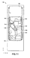
Fig. 11 is a front elevational view of the slide mechanism shown inFig. 10 in a first open position; -
Fig. 12 is a front elevational view of the slide mechanism shown inFig. 10 in a second open position; -
Fig. 13 is a front elevational view of a slide mechanism in accordance with a third embodiment used in the portable electronic device shown inFig. 1 ; and -
Fig. 14 is a front elevational view of a slide mechanism in accordance with a fourth embodiment used in the portable electronic device shown inFig. 1 . - Referring to
Fig. 1 , there is shown a perspective view of a portableelectronic device 10 incorporating features of the invention. Although the invention will be described with reference to the exemplary embodiments shown in the drawings, it should be understood that the invention can be embodied in many alternate forms of embodiments. In addition, any suitable size, shape or type of elements or materials could be used. - In the exemplary embodiment shown in
Figs. 1 and2 , thedevice 10 is a multi function portable electronic device. However, in alternate embodiments, features of the exemplary embodiment of this invention could be used in any suitable type of hand-held portable electronic device such as a mobile phone, a gaming device, a music player, or a PDA, for example. In addition, as is known in the art, thedevice 10 can include features or applications such as a camera, a music player, a game player, or an internet browser, for example. Thedevice 10 generally comprises ahousing 12 andelectronic circuitry 14. Theelectronic circuitry 14 includes, for example, a transceiver, a controller such as a microprocessor, a memory, etc. Thehousing 12 includes afirst housing member 16 and asecond housing member 18. It should be noted that in alternate embodiments, more than two housing members could be provided. - The
second housing member 18 is movably connected to thefirst housing member 16. More specifically, thesecond housing member 18 is slidably mounted to thefirst housing member 16 between a closed position as shown inFigs. 1 and2 , a first open position as shown inFig. 3 , and a second open position as shown inFig. 4 . - As illustrated in
Fig. 3 , thefirst housing member 16 comprises a firstuser input region 20 at afirst end 22 of thefirst housing member 16. The firstuser input region 20 may be a keyboard, a keypad, or a keymat, for example. However, it should be noted that alternate embodiments may provide any suitable type of user input region. The firstuser input region 20 is visible and accessible when thedevice 10 is in the first open position. In this first open position, afirst end 23 of thesecond housing member 18 is above atop end 25 of thedevice 10. - As illustrated in
Fig. 4 , thefirst housing member 16 comprises a seconduser input region 24 at asecond end 26 of thefirst housing member 16. The seconduser input region 24 may comprise control buttons or a keypad, for example. However, it should be noted that alternate embodiments may provide any suitable type of user input region. The seconduser input region 24 is visible and accessible when thedevice 10 is in the second open position. In this second open position, asecond end 27 of thesecond housing member 18 is above abottom end 29 of thedevice 10. - The
second housing member 18 generally comprises adisplay screen 28 and a thirduser input region 30. The thirduser input region 30 may comprise a multi-function key and control keys, for example. However, it should be noted that alternate embodiments may provide any suitable type of user input region. Additionally, the second housing member may comprise acamera 32, alight sensor 34, and anear piece 36, for example. - Referring now to
Figs. 5-8 , there is shown aslide mechanism 38 in accordance with a first embodiment of the invention. The slide mechanism (or slide connection) 38 comprises afirst plate 40, asecond plate 42, and aspring actuator 44. Thefirst plate 40 is configured to be connected to thefirst housing member 16. Thesecond plate 42 is configured to be connected to thesecond housing member 18. Theplates housing members plates housing members slide mechanism 38 is between thefirst plate 40 and thesecond plate 42. The second plate 42 (and the connected second housing member 18) is slidably mounted to the first plate 40 (and the first housing member 16) between the closed position as shown inFig. 5 (and also shown inFigs. 1-2 ), the first open position as shown inFig. 7 (and also shown inFig. 3 ), and the second open position as shown inFig. 8 (and also shown inFig. 4 ). - The
spring actuator 44 is disposed between thefirst plate 40 and thesecond plate 42. The spring actuator comprises a firstspring frame member 46, a secondspring frame member 48, andspring members 50. Thespring members 50 may be coil springs for example. However, alternate embodiments may provide any suitable type springs. Additionally, it should be noted that theactuator 44 does not require springs or spring members. Instead, theactuator 44 may comprise any suitable resiliently deflectable (or resiliently flexible) members. In the embodiment shown, thespring actuator 44 has two spring members, or resilient members, 50. However, in alternate embodiments, any number of spring members could be provided. Opposite ends of thespring members 50 are connected to mount ends 52, 54 of thespring frame members spring frame member 46 and the secondspring frame member 48 are slidably connected to each other such that a spring force of thespring members 50 may be exerted on the mount ends 52, 54. A connectingend 56 of the firstspring frame member 46 is rotatably connected to thefirst plate 40. The connectingend 56 may be attached to first plate, or first module, 40 by riveting or any other suitable method that allows rotational movement. A connectingend 58 of the secondspring frame member 48 is slidably connected to aslot 60 of thesecond plate 42. The connectingend 58 may be attached to the second plate, or second module, 42 by riveting (seerivet 62 inFig. 6 ) or any other suitable method that allows rotational movement, linear sliding, and moving in theslot 60. It should be noted that although the figures illustrate theslot 60 as having a substantially straight linear shape and oriented substantially perpendicular to a length of thedevice 10, alternate embodiments may comprise a slot having any suitable shape or orientation. - The
slide mechanism 38 further comprises acam section 64 attached to thefirst plate 40. Thecam section 40 may be attached to theplate 40 by any suitable means. However, alternate embodiments may provide for a cam section integrally formed with the first plate. Thecam section 64 comprises a first side, or first profile, 66. Thefirst side 66 comprises a generally angled shape extending between twostop regions spring actuator 44. - The connecting
end 58 of the secondspring frame member 48 is configured to slide or move along thefirst side 66 of thecam section 64. Any suitable configuration allowing for the connectingend 58 to slide or roll between thestop regions roller 72 for example. - The
slide mechanism 38 allows for semi-automatic movement of thehousing members device 10 from the closed position (shown inFigs. 1 ,2 , and5 ) to the first open position, which may configure the device to operate in a phone mode for example, (shown inFigs. 3 and7 ), a user would initiate a "long stroke" movement by pushing the second housing member in a vertical direction as shown by the Y-direction arrow 74. This moves thesecond plate 42 in the Y-direction, and moves thespring frame members spring members 50. This movement is provided as the connectingend 56 rotates about the connection to theplate 40, the connectingend 58 rotates within theslot 60, and thesprint actuator 44 generally rotates in a clockwise fashion (wherein the connectingend 58 moves in a first direction of rotation) between the positions ofFig. 5 andFig. 7 . Approximately half way through the movement, the mount ends 52, 54, reach their greatest separation distance and then move towards each other with assistance of the spring force. The spring assisted relative movement of thespring frame members housing members first input region 20. It should be noted that the initial manual movement may be performed by hand or by a trigger for example. The offset or opening length may be any suitable distance such as 30 mm for example. This opening length or "long stroke" can vary in different embodiments. - To return the
device 10 to the configuration ofFigs. 1 ,2 , and5 , the opposite movements are carried out in a similar fashion as the movements described above. 3. As thehousing members Figs. 1 ,2 , and5 , the movement stops at a middle locking position automatically. The "stop" movement is created by a certain combination of spring force of thespring members 50, angle of theslot 60, and thecam profile 66. - To change the configuration of the
device 10 from the closed position (shown inFigs. 1 ,2 , and5 ) to the second open position, which may configure the device to operate in a camera or movie mode, (shown inFigs. 4 and8 ), a user would initiate a "short stroke" movement by pushing the second housing member in a vertical direction opposite to the Y-direction arrow 74. This moves thesecond plate 42 in the direction opposite to the y-direction, and moves thespring frame members spring members 50. This movement is provided as the connectingend 56 rotates about the connection to theplate 40, the connectingend 58 rotates along the length of theslot 60, and thesprint actuator 44 generally rotates in a counterclockwise fashion (wherein the connectingend 58 moves in a second different direction of rotation) between the positions ofFig. 5 andFig. 8 . Approximately half way through the movement, the mount ends 52, 54, reach their greatest separation distance and then move towards each other with assistance of the spring force. The spring assisted relative movement of thespring frame members housing members end 58 from thefirst stop region 68 of thecam section 64 to the second stop region 70 (direction 76) of thecam section 64. This results in the first housing member being offset from the second housing member in the longitudinal direction (Y-direction 74) and allows access to thesecond input region 24. The offset or opening length may be any suitable distance such as 12mm for example. This opening length or "short stroke" can vary in different embodiments. - To return the
device 10 to the configuration ofFigs. 1 ,2 , and5 , the opposite movements are carried out in a similar fashion as the movements described above. As thehousing members Figs. 1 ,2 , and5 , the movement stops at a middle locking position automatically. The "stop" movement is created by a certain combination of spring force of thespring members 50, angle of theslot 60, and thecam profile 66. - It should be noted that the "short stoke" movement may not be a semi-automatic movement due to certain combinations of the
spring members 50, thecam profile 66, and the angle of theslot 60 or because the short stroke is much longer than about 12mm. For example, in one alternate embodiment, the first portion and/or the second portion of the "short stroke" movement may comprise a manual movement. For example, in another alternate embodiment, the portion of the movement returning thehousing members - The invention relates to a semi-automatic dual slide mechanism for a
device 10. One possible use would be for opening and closing a slide phone, thus opening and closing the firstuser input region 20, such as an ITU keymat for example, wherein the rotation of thespring actuator 44 away from thecam section 64 is used to create semi-automatic movement. Another possible use would be for opening and closing a slide phone, thus opening and closing the seconduser input region 24 wherein the rotation of thespring actuator 44 along thecam profile 66 is used to create the semi-automatic movement. Additionally, it should be noted that in alternate embodiments, multi-movements (more than two movements) of thehousing members - Conventional configurations provide spring actuators with semi-automatic function in one direction slides. In one directional slides, both ends of actuator are riveted or some other way stationarily fixed to the sledges or plates in all directions. Dual slides are conventionally done with a spring actuator that provides a force in a horizontal direction (direction perpendicular to Y-direction 74).
- The disclosed slide mechanism provides slide movement in the vertical/longitudinal direction (Y-direction 74). However, it should be noted that the slide mechanism may provide additional slide movements in any suitable direction. Additionally, the disclosed slide mechanism provides the novelty and advantage of combining the two spring assisted sliding principles of the turning spring principle (or "long stroke" movement) and the cam/spring principle (or "short stroke" movement) while using the same spring actuator.
- Further in the prior art cam/spring mechanism the spring force typically is about 90 degrees relative to the sliding direction. Whereas in the invention the spring force turns between about 30 to about 60 degrees in the cam assisted part of the movement.
- The whole sliding mechanism has the advantage of the turning spring principle where the spring force mainly works in or against the sliding direction (but which has only two end positions). And the cam/spring principle which has multiple end/rest positions (but where the spring force needs to be turned about 90 degrees by help of the cam and therefore is a less efficient and less comfortable.)
- The disclosed slide mechanism provides excellent semi-auto function in opening and closing of slide phone when opening and closing ITU keymat. In this solution, the movement down (or "short stroke" movement) is done so that actuator will follow the profile by sliding or with roller. Additionally, revealing and hiding ITU-keys with help of excellent semi-auto function is big advantage. This may result in commercial value wherein disclosed slide mechanism may be used across all suitable applications and competitors (including all mobile phone manufacturers) realize the benefits by this concept.
- Referring now to
Figs. 9-12 , there is shown aslide mechanism 138 in accordance with a second embodiment of the invention. Theslide mechanism 138 is similar to theslide mechanism 38. Theslide mechanism 138 comprises afirst plate 140, asecond plate 142, and aspring actuator 144 as described above with respect to the first embodiment. One difference between theslide mechanism 138 and theslide mechanism 38 is the location and shape of thecam section 164. As illustrated inFig. 10 , thecam section 164 is adjacent to a lateral side of thefirst plate 140. Theprofile 166 of thecam section 164 comprises a non-linear shape. Additionally, theslot 160 comprises an angled configuration. The "long stroke" and "short stroke" movements of theslide mechanism 138 operate in similar fashion as described above for the first embodiment. Another difference between theslide mechanism 138 and theslide mechanism 38 is the configuration of thespring actuator 144. As illustrated inFig. 9-12 , thespring actuator 144 comprises onespring member 150. Thespring member 150 may be a coil spring for example. However, alternate embodiments may provide any suitable type spring. Additionally, it should be noted that theactuator 144 does not require a spring or a spring member. Instead, theactuator 144 may comprise any suitable resiliently deflectable (or resiliently flexible) member. In the embodiment shown, thespring actuator 144 has one spring member, or resilient member, 150. However, in alternate embodiments, any number of spring members could be provided. -
Figs. 9 and10 illustrate a closed position. To change the configuration of the device from the closed position (shown inFigs. 1 ,2 ,9 and10 ) to the first open position (shown inFigs. 3 and11 ), a user would initiate a "long stroke" movement by pushing the second housing member in a vertical direction as shown by the Y-direction arrow 174. This moves thesecond plate 142 in the y-direction, and moves thespring frame members spring member 150. - To change the configuration of the device from the closed position (shown in
Figs. 1 ,2 ,9 , and10 ) to the second open position (shown inFigs. 4 and12 ), a user would initiate a "short stroke" movement by pushing the second housing member in a vertical direction opposite to the Y-direction arrow 174. This moves thesecond plate 142 in the direction opposite to the y-direction arrow 174, and moves thespring frame members spring member 150. - Referring now to
Fig. 13 , there is shown aslide mechanism 238 in accordance with a third embodiment of the invention. Theslide mechanism 238 is similar to theslide mechanism 38. Theslide mechanism 238 comprises afirst plate 240, asecond plate 242, and aspring actuator 244 as described above with respect to the first embodiment. One difference between theslide mechanism 238 and theslide mechanism 38 is the spring configuration. As illustrated inFig. 13 , thespring members 250 extend between thefirst plate 240 and thesecond plate 242 in general curved configuration. The first ends 278 of thespring members 250 are rotatably connected to thefirst plate 240. The second ends 280 of thespring members 250 are slidably connected to theslot 260 of thesecond plate 242. The spring members exert spring forces as they bend (as opposed to exerting forces as a result of extension/compression as in the first and second embodiments). Thespring members 250 may be band springs or leaf springs for example. However, alternate embodiments may provide any suitable type springs. Additionally, it should be noted that theactuator 244 does not require springs or spring members. Instead, theactuator 244 may comprise any suitable resiliently deflectable (or resiliently flexible) member. In the embodiment shown, thespring actuator 244 has three spring members, or resilient members, 250. However, in alternate embodiments, any number of spring members could be provided. The "long stroke" and "short stroke" movements of theslide mechanism 238 operate in similar fashion as described above for the first embodiment. -
Fig. 13 illustrates a closed position. To change the configuration of the device from the closed position (shown inFigs. 1 ,2 , and13 ) to the first open position (shown inFigs. 3 ), a user would initiate a "long stroke" movement by pushing the second housing member in a vertical direction as shown by the Y-direction arrow 274. This moves thesecond plate 242 in the y-direction, wherein the force of thespring members 250 provides similar semi-automatic spring force to that of the first embodiment. - To change the configuration of the device from the closed position (shown in
Figs. 1 ,2 , and13 ) to the second open position (shown inFig. 4 ), a user would initiate a "short stroke" movement by pushing the second housing member in a vertical direction opposite to the Y-direction arrow 274. This moves thesecond plate 242 in the direction opposite to the y-direction arrow 274, wherein the force of thespring members 250 provides similar semi-automatic spring force along thecam profile 266 as that of the first embodiment. - Referring now to
Fig. 14 , there is shown aslide mechanism 338 in accordance with a fourth embodiment of the invention. Theslide mechanism 338 is similar to theslide mechanism 238. Theslide mechanism 338 comprises afirst plate 340, asecond plate 342, and aspring actuator 344 as described above with respect to the third embodiment. One difference between theslide mechanism 338 and theslide mechanism 238 is the orientation of theslot 360 and thecam section 364. Theslot 360 and thecam section 364 comprise generally angled orientations compared to that of theslot 260 and thecam section 264. These orientations allow for the same general "long stroke" and "short stroke" movements as described above. As illustrated inFig. 14 , thespring members 350 extend between thefirst plate 340 and thesecond plate 342 in general curved configuration. The first ends 378 of thespring members 350 are rotatably connected to thefirst plate 340. The second ends 380 of thespring members 350 are slidably connected to theslot 360 of thesecond plate 342. The spring members exert spring forces as they bend and operate in similar fashion as described above for the third embodiment. - The disclosed embodiments of the slide mechanism provide novel elements and features for providing the slide movement between the housing members. In particular, the disclosed slide mechanism provides a suitably sized and shaped spring actuator (which may comprise various configurations), a cam section (which may comprise various cam profile shapes) connected to one of the housing members, and a slot within one of the plates (or slider plates) of the slide mechanism. The disclosed elements provide a novel and improved slide mechanism configuration over conventional slide phones and other electronic devices comprising slide mechanisms.
- It should be understood that the foregoing description is only illustrative of the invention. Various alternatives and modifications can be devised by those skilled in the art without departing from the invention. Accordingly, the invention is intended to embrace all such alternatives, modifications and variances which fall within the scope of the appended claims.
Claims (14)
- An apparatus comprising a slide mechanism, the slide mechanism comprising:a first plate (40);a second plate (42), the second plate comprising a slot (60);a cam section (64) comprising a first profile (66), the cam section (64) being attached to, or integrally formed with, the first plate (40); anda resilient actuator (44),wherein a first connecting end (56) of the resilient actuator (44) is configured to be rotatably connected to the first plate (40), anda second connecting end (58) of the resilient actuator (44) is configured to be movably connected to the slot (60) of the second plate (42) and configured to slide or move or roll along the first profile (66) of the cam section (64), such that:as the first plate (40) is slid with respect to the second plate (42) in a first direction against the bias of the resilient actuator (44) from a first position to a second position, during which the first profile (66) and the second connecting end (58) are operably engaged by virtue of the resilient actuator (44) bias, the second connecting end (58) of the resilient actuator (44) is configured to move by:sliding along the slot (60); andsliding or rolling along the first profile (66) of the cam section (64); andas the first plate (40) is slid with respect to the second plate (42) in a second direction opposite to the first direction, from the first position to a third position, the third position being a position in which the first profile (66) and the second connecting end (58) are operably disengaged:the first connecting end (56) is rotated about its rotatable connection to the first plate (40);the second connecting end (58) is rotated within the slot (60); andthe resilient actuator (44) is semi-automatically rotated through a first movement portion where the resilient actuator (44) is moved to overcome the bias of the resilient actuator (44) and a second movement portion which is automatic under the bias of the resilient actuator (44).
- The apparatus as claimed in claim 1 wherein the second plate (42) is configured to be movable in the first direction between the three positions from the third position, to the first position and then onto the second position.
- The apparatus as claimed in claim 2 wherein the second plate (42) is configured to be movable in the second direction between the three positions, from the second position, to the first position, and then onto the third position.
- The apparatus as claimed in any preceding claim wherein the slide mechanism is configured to automatically stop the second plate (42) at the second position when the second plate (42) moves in the first direction with respect to the first plate (40).
- The apparatus as claimed in any preceding claim wherein the second plate (42) is configured to be manually moveable with respect to the first plate (40) in at least one direction.
- The apparatus as claimed in any preceding claim wherein the slide mechanism is configured to semi-automatically move the first plate (40) with respect to the second plate (42) from the first position to the second position.
- The apparatus of any preceding claim, wherein the slot (60) has a substantially straight linear shape and is configured to be oriented substantially perpendicular to the sliding axis of the first direction.
- The apparatus of any preceding claim, wherein the apparatus is a portable electronic device.
- The apparatus of any preceding claims, wherein the apparatus is a mobile phone, gaming device or a PDA.
- The apparatus of claim 1, wherein the second plate (42) is configured to be movable in a first longitudinal direction relative to the first plate (40) when the resilient actuator (44) rotates in a first direction of rotation, and wherein the second plate (42) is configured to be movable in a second different opposing longitudinal direction relative to the first plate (40) when the resilient actuator (44) rotates in a second different direction of rotation.
- The apparatus as claimed in claim 1 wherein the angle between the resilient actuator (44) when In the second position and when in the third position is about 90 degrees.
- The apparatus as claimed in claim 1 wherein the angle between the resilient actuator (44) when in the second position and when in the third position is about 30 degrees to about 60 degrees.
- The apparatus as claimed in claim 1 wherein the first profile has a generally angled shape extending between two stop regions (68, 70).
- A method of manufacturing an apparatus, the method comprising:providing a first plate (40);providing a second plate (42), the second plate comprising a slot (60);providing a cam section (64) comprising a first profile (66), the cam section being attached to, or integrally formed with, the first plate (40); andproviding a resilient actuator (44),wherein a first connecting end (56) of the resilient actuator (44) is configured to be rotatably connected to the first plate (40),wherein a second connecting end (58) of the resilient actuator (44) is configured to be movably connected to the slot (60) of the second plate (42) and configured to slide or move or roll along the first profile (66) of the cam section (64), such that:as the first plate (40) is slid with respect to the second plate (42) in a first direction against the bias of the resilient actuator (44) from a first position to a second position, during which the first profile (66) and the second connecting end (58) are operably engaged, the second connecting end (58) of the resilient actuator (44) is configured to:slide along the slot (60); andslide or roll along the first profile (66) of the cam section (64); andas the first plate (40) is slid with respect to the second plate (42) in a second direction opposite to the first direction, from the first position to a third position, the third position being a position in which the first profile (66) and the second connecting end (58) are operably disengaged:the first connecting end (56) is configured to rotate about its rotatable connection to the first plate (40);the second connecting end (58) is configured to rotate within the slot (60); andthe resilient actuator (44) is configured to semi-automatically rotate through a first movement portion where the resilient actuator (44) is configured to move to overcome the bias of the resilient actuator (44) and a second movement portion which is configured to be automatic under the bias of the resilient actuator (44).
Applications Claiming Priority (3)
| Application Number | Priority Date | Filing Date | Title |
|---|---|---|---|
| US93771207P | 2007-06-29 | 2007-06-29 | |
| US11/904,505 US20090005135A1 (en) | 2007-06-29 | 2007-09-26 | Electronic device slide mechanism |
| PCT/IB2008/052553 WO2009004536A2 (en) | 2007-06-29 | 2008-06-25 | Electronic device slide- mechanism adapted to slide in two directions |
Publications (2)
| Publication Number | Publication Date |
|---|---|
| EP2168362A2 EP2168362A2 (en) | 2010-03-31 |
| EP2168362B1 true EP2168362B1 (en) | 2014-08-13 |
Family
ID=40161267
Family Applications (1)
| Application Number | Title | Priority Date | Filing Date |
|---|---|---|---|
| EP08776512.9A Not-in-force EP2168362B1 (en) | 2007-06-29 | 2008-06-25 | Electronic device slide mechanism |
Country Status (6)
| Country | Link |
|---|---|
| US (1) | US20090005135A1 (en) |
| EP (1) | EP2168362B1 (en) |
| KR (1) | KR101124792B1 (en) |
| CN (1) | CN101720549A (en) |
| BR (1) | BRPI0812898A2 (en) |
| WO (1) | WO2009004536A2 (en) |
Families Citing this family (16)
| Publication number | Priority date | Publication date | Assignee | Title |
|---|---|---|---|---|
| US20070180652A1 (en) * | 2006-01-25 | 2007-08-09 | Makoto Miyamoto | Opening and closing device |
| US7853301B2 (en) * | 2006-09-19 | 2010-12-14 | Samsung Electronics Co., Ltd | Sliding module for double sliding-type portable communication terminal |
| CN101460033A (en) * | 2007-12-11 | 2009-06-17 | 鸿富锦精密工业(深圳)有限公司 | Sliding mechanism |
| US8064973B2 (en) * | 2007-12-20 | 2011-11-22 | Nokia Corporation | Electronic device with integrated slide |
| US8224407B2 (en) * | 2009-03-23 | 2012-07-17 | T-Mobile Usa, Inc. | Mobile device having a movable display and associated systems and methods |
| US8023975B2 (en) * | 2009-03-23 | 2011-09-20 | T-Mobile Usa, Inc. | Secondary status display for mobile device |
| US8391935B2 (en) * | 2009-03-23 | 2013-03-05 | T-Mobile Usa, Inc. | Multifunction mobile device having a movable element, such as a display, and associated functions |
| JP2010288248A (en) * | 2009-05-15 | 2010-12-24 | Fujitsu Ltd | Portable device |
| KR101354217B1 (en) * | 2009-08-07 | 2014-01-22 | 삼성전자주식회사 | Display apparatus and complex entertainment apparatus having the same |
| JP4781473B1 (en) * | 2010-03-11 | 2011-09-28 | 三菱製鋼株式会社 | Spring unit and slide mechanism |
| US8427829B2 (en) * | 2011-05-06 | 2013-04-23 | Shin Zu Shing Co., Ltd. | Dual directional sliding hinge and portable device |
| CN102858117A (en) * | 2011-06-30 | 2013-01-02 | 深圳富泰宏精密工业有限公司 | Sliding mechanism |
| US8657497B2 (en) * | 2011-07-29 | 2014-02-25 | First Dome Corporation | Slide-rail stabilizing structure of relative sliding device |
| CN103152447B (en) * | 2011-12-07 | 2016-03-30 | 宏达国际电子股份有限公司 | Hand-hold electronic device |
| KR20150051773A (en) * | 2013-11-05 | 2015-05-13 | 엘지전자 주식회사 | Mobile terminal |
| CN111614817B (en) * | 2020-05-27 | 2021-06-04 | 维沃移动通信有限公司 | Electronic device |
Family Cites Families (8)
| Publication number | Priority date | Publication date | Assignee | Title |
|---|---|---|---|---|
| JP4252004B2 (en) * | 2004-03-17 | 2009-04-08 | 加藤電機株式会社 | Semi-automatic slide device |
| US7289044B2 (en) * | 2004-06-02 | 2007-10-30 | Research In Motion Limited | Handheld electronic device with text disambiguation |
| KR200361808Y1 (en) * | 2004-06-04 | 2004-09-16 | 조용수 | Slide type semi-auto driving apparatus of portable wireless phone |
| WO2006098590A1 (en) | 2005-03-16 | 2006-09-21 | Jong Chul Choo | Sliding unit and electronic device using it |
| KR20070008363A (en) * | 2005-07-13 | 2007-01-17 | 추종철 | Muti-level sliding unit |
| KR100909474B1 (en) * | 2005-08-10 | 2009-07-28 | 삼성전자주식회사 | Methods for Detecting Defective Semiconductor Wafers with Local Defect Mode Using Wafer Defect Index and Equipments Used Thereon |
| US20070060220A1 (en) * | 2005-09-14 | 2007-03-15 | An-Szu Hsu | Gliding structure for glide-open type mobile phone |
| KR100843584B1 (en) * | 2007-04-10 | 2008-07-03 | 암페놀피닉스 주식회사 | Sliding type opening and closing apparatus for use in portable telephone |
-
2007
- 2007-09-26 US US11/904,505 patent/US20090005135A1/en not_active Abandoned
-
2008
- 2008-06-25 WO PCT/IB2008/052553 patent/WO2009004536A2/en active Application Filing
- 2008-06-25 EP EP08776512.9A patent/EP2168362B1/en not_active Not-in-force
- 2008-06-25 CN CN200880022815A patent/CN101720549A/en active Pending
- 2008-06-25 BR BRPI0812898-7A2A patent/BRPI0812898A2/en not_active IP Right Cessation
- 2008-06-25 KR KR1020107002063A patent/KR101124792B1/en active IP Right Grant
Also Published As
| Publication number | Publication date |
|---|---|
| WO2009004536A3 (en) | 2009-02-19 |
| EP2168362A2 (en) | 2010-03-31 |
| CN101720549A (en) | 2010-06-02 |
| WO2009004536A2 (en) | 2009-01-08 |
| US20090005135A1 (en) | 2009-01-01 |
| KR20100049047A (en) | 2010-05-11 |
| BRPI0812898A2 (en) | 2014-12-09 |
| KR101124792B1 (en) | 2012-03-23 |
Similar Documents
| Publication | Publication Date | Title |
|---|---|---|
| EP2168362B1 (en) | Electronic device slide mechanism | |
| JP5599226B2 (en) | Switchgear | |
| EP1786181B1 (en) | Portable phone with sliding module for sliding housings in two different directions | |
| US8363391B2 (en) | Portable terminal | |
| US8411421B2 (en) | Open-close type compact electronic device | |
| EP1758343A2 (en) | Hinge device for portable terminal and portable terminal having the same | |
| US7751195B2 (en) | Electronic device slide and tilt mechanism | |
| JP2005210649A (en) | Sliding mechanism of mobile terminal | |
| KR20060019213A (en) | Sliding module for portable terminal | |
| EP2600594B1 (en) | Opening/closing apparatus | |
| US8620396B2 (en) | Slide mechanism and electronic apparatus | |
| EP1814285B1 (en) | Sliding/swing-type portable terminal capable of positioning liquid crystal display at center portion thereof and method of using the same | |
| EP1830542A2 (en) | Spring loaded sliding mechanism for a portable electronic device | |
| KR100796719B1 (en) | Slide hinge apparatus | |
| JP2008092264A (en) | Hinge mechanism and portable terminal | |
| EP2285074B1 (en) | Handheld electronic device and rising mechanism | |
| JP2006186201A (en) | Slide mechanism and mobile terminal | |
| KR101756147B1 (en) | Slim Type Tilting Hinge and Electric Device having it | |
| KR101094164B1 (en) | A terminal | |
| US8213169B2 (en) | Sliding hinge and a portable electronic device | |
| KR100998877B1 (en) | Hinge apparatus and portable terminal using the same | |
| JP5135241B2 (en) | Slide rotation hinge | |
| KR100716758B1 (en) | Swing type personal portable device | |
| KR101235940B1 (en) | Opening-closing device of small electronic apparatus and small electronic apparatus | |
| JP5124060B2 (en) | Slide rotation hinge |
Legal Events
| Date | Code | Title | Description |
|---|---|---|---|
| PUAI | Public reference made under article 153(3) epc to a published international application that has entered the european phase |
Free format text: ORIGINAL CODE: 0009012 |
|
| 17P | Request for examination filed |
Effective date: 20100113 |
|
| AK | Designated contracting states |
Kind code of ref document: A2 Designated state(s): AT BE BG CH CY CZ DE DK EE ES FI FR GB GR HR HU IE IS IT LI LT LU LV MC MT NL NO PL PT RO SE SI SK TR |
|
| AX | Request for extension of the european patent |
Extension state: AL BA MK RS |
|
| 17Q | First examination report despatched |
Effective date: 20100419 |
|
| DAX | Request for extension of the european patent (deleted) | ||
| GRAP | Despatch of communication of intention to grant a patent |
Free format text: ORIGINAL CODE: EPIDOSNIGR1 |
|
| INTG | Intention to grant announced |
Effective date: 20140221 |
|
| RAP1 | Party data changed (applicant data changed or rights of an application transferred) |
Owner name: NOKIA CORPORATION |
|
| GRAS | Grant fee paid |
Free format text: ORIGINAL CODE: EPIDOSNIGR3 |
|
| GRAA | (expected) grant |
Free format text: ORIGINAL CODE: 0009210 |
|
| AK | Designated contracting states |
Kind code of ref document: B1 Designated state(s): AT BE BG CH CY CZ DE DK EE ES FI FR GB GR HR HU IE IS IT LI LT LU LV MC MT NL NO PL PT RO SE SI SK TR |
|
| RAP1 | Party data changed (applicant data changed or rights of an application transferred) |
Owner name: NOKIA CORPORATION |
|
| REG | Reference to a national code |
Ref country code: GB Ref legal event code: FG4D |
|
| REG | Reference to a national code |
Ref country code: AT Ref legal event code: REF Ref document number: 682803 Country of ref document: AT Kind code of ref document: T Effective date: 20140815 Ref country code: CH Ref legal event code: EP |
|
| REG | Reference to a national code |
Ref country code: IE Ref legal event code: FG4D |
|
| REG | Reference to a national code |
Ref country code: DE Ref legal event code: R096 Ref document number: 602008033856 Country of ref document: DE Effective date: 20140925 |
|
| REG | Reference to a national code |
Ref country code: NL Ref legal event code: VDEP Effective date: 20140813 |
|
| REG | Reference to a national code |
Ref country code: AT Ref legal event code: MK05 Ref document number: 682803 Country of ref document: AT Kind code of ref document: T Effective date: 20140813 |
|
| REG | Reference to a national code |
Ref country code: LT Ref legal event code: MG4D |
|
| PG25 | Lapsed in a contracting state [announced via postgrant information from national office to epo] |
Ref country code: LT Free format text: LAPSE BECAUSE OF FAILURE TO SUBMIT A TRANSLATION OF THE DESCRIPTION OR TO PAY THE FEE WITHIN THE PRESCRIBED TIME-LIMIT Effective date: 20140813 Ref country code: FI Free format text: LAPSE BECAUSE OF FAILURE TO SUBMIT A TRANSLATION OF THE DESCRIPTION OR TO PAY THE FEE WITHIN THE PRESCRIBED TIME-LIMIT Effective date: 20140813 Ref country code: SE Free format text: LAPSE BECAUSE OF FAILURE TO SUBMIT A TRANSLATION OF THE DESCRIPTION OR TO PAY THE FEE WITHIN THE PRESCRIBED TIME-LIMIT Effective date: 20140813 Ref country code: PT Free format text: LAPSE BECAUSE OF FAILURE TO SUBMIT A TRANSLATION OF THE DESCRIPTION OR TO PAY THE FEE WITHIN THE PRESCRIBED TIME-LIMIT Effective date: 20141215 Ref country code: BG Free format text: LAPSE BECAUSE OF FAILURE TO SUBMIT A TRANSLATION OF THE DESCRIPTION OR TO PAY THE FEE WITHIN THE PRESCRIBED TIME-LIMIT Effective date: 20141113 Ref country code: NO Free format text: LAPSE BECAUSE OF FAILURE TO SUBMIT A TRANSLATION OF THE DESCRIPTION OR TO PAY THE FEE WITHIN THE PRESCRIBED TIME-LIMIT Effective date: 20141113 Ref country code: GR Free format text: LAPSE BECAUSE OF FAILURE TO SUBMIT A TRANSLATION OF THE DESCRIPTION OR TO PAY THE FEE WITHIN THE PRESCRIBED TIME-LIMIT Effective date: 20141114 Ref country code: ES Free format text: LAPSE BECAUSE OF FAILURE TO SUBMIT A TRANSLATION OF THE DESCRIPTION OR TO PAY THE FEE WITHIN THE PRESCRIBED TIME-LIMIT Effective date: 20140813 |
|
| PG25 | Lapsed in a contracting state [announced via postgrant information from national office to epo] |
Ref country code: LV Free format text: LAPSE BECAUSE OF FAILURE TO SUBMIT A TRANSLATION OF THE DESCRIPTION OR TO PAY THE FEE WITHIN THE PRESCRIBED TIME-LIMIT Effective date: 20140813 Ref country code: IS Free format text: LAPSE BECAUSE OF FAILURE TO SUBMIT A TRANSLATION OF THE DESCRIPTION OR TO PAY THE FEE WITHIN THE PRESCRIBED TIME-LIMIT Effective date: 20141213 Ref country code: CY Free format text: LAPSE BECAUSE OF FAILURE TO SUBMIT A TRANSLATION OF THE DESCRIPTION OR TO PAY THE FEE WITHIN THE PRESCRIBED TIME-LIMIT Effective date: 20140813 Ref country code: HR Free format text: LAPSE BECAUSE OF FAILURE TO SUBMIT A TRANSLATION OF THE DESCRIPTION OR TO PAY THE FEE WITHIN THE PRESCRIBED TIME-LIMIT Effective date: 20140813 Ref country code: AT Free format text: LAPSE BECAUSE OF FAILURE TO SUBMIT A TRANSLATION OF THE DESCRIPTION OR TO PAY THE FEE WITHIN THE PRESCRIBED TIME-LIMIT Effective date: 20140813 |
|
| PG25 | Lapsed in a contracting state [announced via postgrant information from national office to epo] |
Ref country code: NL Free format text: LAPSE BECAUSE OF FAILURE TO SUBMIT A TRANSLATION OF THE DESCRIPTION OR TO PAY THE FEE WITHIN THE PRESCRIBED TIME-LIMIT Effective date: 20140813 |
|
| PG25 | Lapsed in a contracting state [announced via postgrant information from national office to epo] |
Ref country code: DK Free format text: LAPSE BECAUSE OF FAILURE TO SUBMIT A TRANSLATION OF THE DESCRIPTION OR TO PAY THE FEE WITHIN THE PRESCRIBED TIME-LIMIT Effective date: 20140813 Ref country code: EE Free format text: LAPSE BECAUSE OF FAILURE TO SUBMIT A TRANSLATION OF THE DESCRIPTION OR TO PAY THE FEE WITHIN THE PRESCRIBED TIME-LIMIT Effective date: 20140813 Ref country code: IT Free format text: LAPSE BECAUSE OF FAILURE TO SUBMIT A TRANSLATION OF THE DESCRIPTION OR TO PAY THE FEE WITHIN THE PRESCRIBED TIME-LIMIT Effective date: 20140813 Ref country code: RO Free format text: LAPSE BECAUSE OF FAILURE TO SUBMIT A TRANSLATION OF THE DESCRIPTION OR TO PAY THE FEE WITHIN THE PRESCRIBED TIME-LIMIT Effective date: 20140813 Ref country code: CZ Free format text: LAPSE BECAUSE OF FAILURE TO SUBMIT A TRANSLATION OF THE DESCRIPTION OR TO PAY THE FEE WITHIN THE PRESCRIBED TIME-LIMIT Effective date: 20140813 Ref country code: SK Free format text: LAPSE BECAUSE OF FAILURE TO SUBMIT A TRANSLATION OF THE DESCRIPTION OR TO PAY THE FEE WITHIN THE PRESCRIBED TIME-LIMIT Effective date: 20140813 |
|
| REG | Reference to a national code |
Ref country code: DE Ref legal event code: R097 Ref document number: 602008033856 Country of ref document: DE |
|
| PG25 | Lapsed in a contracting state [announced via postgrant information from national office to epo] |
Ref country code: PL Free format text: LAPSE BECAUSE OF FAILURE TO SUBMIT A TRANSLATION OF THE DESCRIPTION OR TO PAY THE FEE WITHIN THE PRESCRIBED TIME-LIMIT Effective date: 20140813 |
|
| PLBE | No opposition filed within time limit |
Free format text: ORIGINAL CODE: 0009261 |
|
| STAA | Information on the status of an ep patent application or granted ep patent |
Free format text: STATUS: NO OPPOSITION FILED WITHIN TIME LIMIT |
|
| 26N | No opposition filed |
Effective date: 20150515 |
|
| REG | Reference to a national code |
Ref country code: DE Ref legal event code: R081 Ref document number: 602008033856 Country of ref document: DE Owner name: NOKIA TECHNOLOGIES OY, FI Free format text: FORMER OWNER: NOKIA CORPORATION, ESPOO, FI Ref country code: DE Ref legal event code: R081 Ref document number: 602008033856 Country of ref document: DE Owner name: NOKIA TECHNOLOGIES OY, FI Free format text: FORMER OWNER: NOKIA CORPORATION, 02610 ESPOO, FI |
|
| PG25 | Lapsed in a contracting state [announced via postgrant information from national office to epo] |
Ref country code: SI Free format text: LAPSE BECAUSE OF FAILURE TO SUBMIT A TRANSLATION OF THE DESCRIPTION OR TO PAY THE FEE WITHIN THE PRESCRIBED TIME-LIMIT Effective date: 20140813 |
|
| PG25 | Lapsed in a contracting state [announced via postgrant information from national office to epo] |
Ref country code: MC Free format text: LAPSE BECAUSE OF FAILURE TO SUBMIT A TRANSLATION OF THE DESCRIPTION OR TO PAY THE FEE WITHIN THE PRESCRIBED TIME-LIMIT Effective date: 20140813 |
|
| REG | Reference to a national code |
Ref country code: CH Ref legal event code: PL |
|
| GBPC | Gb: european patent ceased through non-payment of renewal fee |
Effective date: 20150625 |
|
| PG25 | Lapsed in a contracting state [announced via postgrant information from national office to epo] |
Ref country code: LU Free format text: LAPSE BECAUSE OF FAILURE TO SUBMIT A TRANSLATION OF THE DESCRIPTION OR TO PAY THE FEE WITHIN THE PRESCRIBED TIME-LIMIT Effective date: 20150625 |
|
| REG | Reference to a national code |
Ref country code: IE Ref legal event code: MM4A |
|
| REG | Reference to a national code |
Ref country code: FR Ref legal event code: ST Effective date: 20160229 |
|
| PG25 | Lapsed in a contracting state [announced via postgrant information from national office to epo] |
Ref country code: IE Free format text: LAPSE BECAUSE OF NON-PAYMENT OF DUE FEES Effective date: 20150625 Ref country code: CH Free format text: LAPSE BECAUSE OF NON-PAYMENT OF DUE FEES Effective date: 20150630 Ref country code: LI Free format text: LAPSE BECAUSE OF NON-PAYMENT OF DUE FEES Effective date: 20150630 Ref country code: GB Free format text: LAPSE BECAUSE OF NON-PAYMENT OF DUE FEES Effective date: 20150625 |
|
| PG25 | Lapsed in a contracting state [announced via postgrant information from national office to epo] |
Ref country code: FR Free format text: LAPSE BECAUSE OF NON-PAYMENT OF DUE FEES Effective date: 20150630 |
|
| PG25 | Lapsed in a contracting state [announced via postgrant information from national office to epo] |
Ref country code: BE Free format text: LAPSE BECAUSE OF FAILURE TO SUBMIT A TRANSLATION OF THE DESCRIPTION OR TO PAY THE FEE WITHIN THE PRESCRIBED TIME-LIMIT Effective date: 20140813 |
|
| PG25 | Lapsed in a contracting state [announced via postgrant information from national office to epo] |
Ref country code: MT Free format text: LAPSE BECAUSE OF FAILURE TO SUBMIT A TRANSLATION OF THE DESCRIPTION OR TO PAY THE FEE WITHIN THE PRESCRIBED TIME-LIMIT Effective date: 20140813 |
|
| PG25 | Lapsed in a contracting state [announced via postgrant information from national office to epo] |
Ref country code: HU Free format text: LAPSE BECAUSE OF FAILURE TO SUBMIT A TRANSLATION OF THE DESCRIPTION OR TO PAY THE FEE WITHIN THE PRESCRIBED TIME-LIMIT; INVALID AB INITIO Effective date: 20080625 |
|
| PG25 | Lapsed in a contracting state [announced via postgrant information from national office to epo] |
Ref country code: TR Free format text: LAPSE BECAUSE OF FAILURE TO SUBMIT A TRANSLATION OF THE DESCRIPTION OR TO PAY THE FEE WITHIN THE PRESCRIBED TIME-LIMIT Effective date: 20140813 |
|
| PGFP | Annual fee paid to national office [announced via postgrant information from national office to epo] |
Ref country code: DE Payment date: 20180612 Year of fee payment: 11 |
|
| REG | Reference to a national code |
Ref country code: DE Ref legal event code: R119 Ref document number: 602008033856 Country of ref document: DE |
|
| PG25 | Lapsed in a contracting state [announced via postgrant information from national office to epo] |
Ref country code: DE Free format text: LAPSE BECAUSE OF NON-PAYMENT OF DUE FEES Effective date: 20200101 |