EP1814285B1 - Sliding/swing-type portable terminal capable of positioning liquid crystal display at center portion thereof and method of using the same - Google Patents
Sliding/swing-type portable terminal capable of positioning liquid crystal display at center portion thereof and method of using the same Download PDFInfo
- Publication number
- EP1814285B1 EP1814285B1 EP07001386A EP07001386A EP1814285B1 EP 1814285 B1 EP1814285 B1 EP 1814285B1 EP 07001386 A EP07001386 A EP 07001386A EP 07001386 A EP07001386 A EP 07001386A EP 1814285 B1 EP1814285 B1 EP 1814285B1
- Authority
- EP
- European Patent Office
- Prior art keywords
- sliding
- housing
- swing
- guide
- portable terminal
- Prior art date
- Legal status (The legal status is an assumption and is not a legal conclusion. Google has not performed a legal analysis and makes no representation as to the accuracy of the status listed.)
- Ceased
Links
- 238000000034 method Methods 0.000 title claims description 4
- 239000004973 liquid crystal related substance Substances 0.000 title description 56
- 238000004891 communication Methods 0.000 description 5
- 210000000707 wrist Anatomy 0.000 description 3
- 238000010276 construction Methods 0.000 description 2
- 238000004519 manufacturing process Methods 0.000 description 2
- 230000001413 cellular effect Effects 0.000 description 1
- 230000007547 defect Effects 0.000 description 1
- 238000012986 modification Methods 0.000 description 1
- 230000004048 modification Effects 0.000 description 1
Images


Classifications
-
- H—ELECTRICITY
- H04—ELECTRIC COMMUNICATION TECHNIQUE
- H04M—TELEPHONIC COMMUNICATION
- H04M1/00—Substation equipment, e.g. for use by subscribers
- H04M1/02—Constructional features of telephone sets
- H04M1/0202—Portable telephone sets, e.g. cordless phones, mobile phones or bar type handsets
- H04M1/0206—Portable telephones comprising a plurality of mechanically joined movable body parts, e.g. hinged housings
- H04M1/0208—Portable telephones comprising a plurality of mechanically joined movable body parts, e.g. hinged housings characterized by the relative motions of the body parts
- H04M1/0235—Slidable or telescopic telephones, i.e. with a relative translation movement of the body parts; Telephones using a combination of translation and other relative motions of the body parts
- H04M1/0237—Sliding mechanism with one degree of freedom
-
- G—PHYSICS
- G06—COMPUTING; CALCULATING OR COUNTING
- G06F—ELECTRIC DIGITAL DATA PROCESSING
- G06F1/00—Details not covered by groups G06F3/00 - G06F13/00 and G06F21/00
- G06F1/16—Constructional details or arrangements
- G06F1/1613—Constructional details or arrangements for portable computers
- G06F1/1615—Constructional details or arrangements for portable computers with several enclosures having relative motions, each enclosure supporting at least one I/O or computing function
- G06F1/1622—Constructional details or arrangements for portable computers with several enclosures having relative motions, each enclosure supporting at least one I/O or computing function with enclosures rotating around an axis perpendicular to the plane they define or with ball-joint coupling, e.g. PDA with display enclosure orientation changeable between portrait and landscape by rotation with respect to a coplanar body enclosure
-
- G—PHYSICS
- G06—COMPUTING; CALCULATING OR COUNTING
- G06F—ELECTRIC DIGITAL DATA PROCESSING
- G06F1/00—Details not covered by groups G06F3/00 - G06F13/00 and G06F21/00
- G06F1/16—Constructional details or arrangements
- G06F1/1613—Constructional details or arrangements for portable computers
- G06F1/1615—Constructional details or arrangements for portable computers with several enclosures having relative motions, each enclosure supporting at least one I/O or computing function
- G06F1/1624—Constructional details or arrangements for portable computers with several enclosures having relative motions, each enclosure supporting at least one I/O or computing function with sliding enclosures, e.g. sliding keyboard or display
-
- G—PHYSICS
- G06—COMPUTING; CALCULATING OR COUNTING
- G06F—ELECTRIC DIGITAL DATA PROCESSING
- G06F1/00—Details not covered by groups G06F3/00 - G06F13/00 and G06F21/00
- G06F1/16—Constructional details or arrangements
- G06F1/1613—Constructional details or arrangements for portable computers
- G06F1/1633—Constructional details or arrangements of portable computers not specific to the type of enclosures covered by groups G06F1/1615 - G06F1/1626
- G06F1/1675—Miscellaneous details related to the relative movement between the different enclosures or enclosure parts
- G06F1/1681—Details related solely to hinges
-
- H—ELECTRICITY
- H04—ELECTRIC COMMUNICATION TECHNIQUE
- H04M—TELEPHONIC COMMUNICATION
- H04M1/00—Substation equipment, e.g. for use by subscribers
- H04M1/02—Constructional features of telephone sets
- H04M1/0202—Portable telephone sets, e.g. cordless phones, mobile phones or bar type handsets
- H04M1/0206—Portable telephones comprising a plurality of mechanically joined movable body parts, e.g. hinged housings
- H04M1/0208—Portable telephones comprising a plurality of mechanically joined movable body parts, e.g. hinged housings characterized by the relative motions of the body parts
- H04M1/0225—Rotatable telephones, i.e. the body parts pivoting to an open position around an axis perpendicular to the plane they define in closed position
- H04M1/0233—Including a rotatable display body part
Definitions
- the present invention relates to a sliding/swing-type portable terminal comprising a liquid crystal display. More particularly, the present invention relates to a portable terminal which can guide and move the liquid crystal display toward a center portion thereof when the terminal rotates.
- Portable communication terminals generally refer to electronic devices which may be carried with a user while the user communicates wirelessly with another user.
- portable communication devices include Hand-Held Phones (HHP), CT-2, cellular phones, digital phones, Personal Communication System (PCS) phones, and Personal Digital Assistants (PDAs).
- HPHP Hand-Held Phones
- CT-2 CT-2
- cellular phones digital phones
- PCS Personal Communication System
- PDAs Personal Digital Assistants
- Conventional portable terminals may be classified into various types according to their appearance, such as bar-type portable terminals, flip-type portable terminals, and folder-type portable terminals.
- the bar-type portable terminal has a single housing shaped like a bar.
- the flip-type portable terminal has a flip panel which is pivotally mounted to a bar-shaped housing by a hinge unit.
- the folder-type portable terminal has a folder coupled to a single bar-shaped housing by a hinge unit that facilitates the rotation of the folder so that it can be folded or unfolded from the housing.
- portable terminals may be classified as neck wearable-type terminals and wrist wearable-type terminals, according to the position or way in which a user wears the terminal. A user wears the neck wearable-type terminal around the neck using a lanyard or necklace. Alternatively, the user wears the wrist wearable-type terminal around the wrist.
- portable terminals may be classified as rotation-type terminals, sliding-type terminals, and sliding/swing-type terminals according to the manner of opening and closing the terminal.
- two housings are coupled to each other in a manner such that one housing rotates to be opened or closed relative to the other while facing each other.
- two housings are coupled to each other in a manner such that one housing slides to be opened or closed relative to the other.
- two housing are coupled to each other in a manner that one housing swings on the other after sliding on the other housing.
- the conventional portable terminal essentially includes an antenna, data input/output units, data transmitter and data receiver.
- a keypad is used as the data input unit, on which a user can press keys with his/her fingers to input data.
- a touch pad or a touch screen may also be used as the data input unit.
- a liquid crystal display unit is also generally used as the data output unit to display data.
- the conventional portable terminal may be provided with a camera lens. Therefore, it is possible to perform image communication with a desired partner or to photograph a desired subject.
- the sliding/swing-type portable terminal 10 includes a body housing 20, a sliding housing 30 sliding and swinging on the body housing 20 to be opened and closed while facing the body housing 20.
- the sliding/swing-type portable terminal 10 also includes a sliding/swing hinge device 40 to allow the sliding housing 30 to slide and swing on the body housing 20.
- FIGS. 1 and 2 illustrate the body housing 20 with a keypad 21 including a plurality of keys arranged thereon.
- the sliding housing 30 also includes a liquid crystal display unit 31.
- the liquid crystal display unit of the sliding housing is located in a position that does not have a common center with the center portion of the body housing when the sliding housing slides and swings. Accordingly, the liquid crystal display unit must be inconveniently shifted to the center portion of the body housing after the sliding housing swings.
- the hinge device In order to overcome the above-mentioned defect, the hinge device must have a separate guide unit and stopper. In this case, the portable terminal is required to have sufficient space to mount the guide unit and stopper. This produces an increase in the volume of the portable terminal and reduces the ability of the portable terminal to be miniaturized. In addition, there is an increase in the number of parts which thereby increases manufacturing costs and assembly time.
- US 2004137940 discloses a portable wireless terminal device which has a main body comprising a first case provided with a plurality of manual keys, a second case provided with a display having a rectangular screen of a predetermined aspect ratio, and a connecting mechanism for interconnecting the two cases.
- the connecting mechanism comprises a pivot mechanism for rotating the second case relative to the first case along a plane parallel to the screen.
- the display is activated in a screen position wherein the screen is elongated vertically.
- the display is activated in a screen position wherein the screen is elongated horizontally.
- an object of exemplary embodiments of the present invention is to address at least the above problems and/or disadvantages and to provide at least the advantages described below. Accordingly, an object of exemplary embodiments of the present invention is to provide a sliding/swing-type portable terminal having a liquid crystal display unit, which has a guide device to guide the liquid crystal display unit to a center portion of the terminal when the terminal swings, thereby improving the displaying function of the liquid crystal display unit and user's convenience.
- a sliding/swing-type portable terminal with a liquid crystal display unit is provided.
- a hinge device is eccentrically mounted on the terminal to facilitate the shift of the liquid crystal display unit along the hinge axis of the eccentric hinge device to the center portion of the terminal.
- a swing-type portable terminal is provided.
- a swing housing can swing clockwise and counterclockwise along a desired trajectory and a central axis of the swing housing can be shifted, thereby positioning the liquid crystal display unit of the swing housing at the center portion of the body housing.
- a sliding/swing-type portable terminal comprises a body housing, a sliding housing and a sliding/swing hinge device.
- the sliding housing is provided with a liquid crystal display unit and sliding and swinging on the body housing to be opened and closed.
- the sliding/swing hinge device allows the sliding housing to slide and swing on the body housing and includes a guide bar provided on the sliding housing and a guide member provided to the body housing for guiding the sliding and swinging movement of the guide bar.
- the guide member guides the movement of the guide bar at a termination position of the sliding movement of the sliding housing so that the liquid crystal display unit of the sliding housing is positioned at a center portion of the body housing.
- a swing-type portable terminal comprises a body housing, a swing housing, a guide pin and at least one guide member.
- a swing housing is provided with a liquid crystal display unit and rotates around a hinge axis extending perpendicularly to an upper surface of the body housing while facing the body housing.
- a guide pin is provided to the swing housing.
- At least one guide member is provided to the body housing to guide the movement of the guide pin along a predetermined trajectory to move a central axis of the swing housing when the swing housing swings clockwise or counterclockwise and to position the liquid crystal display unit of the swing housing at the center portion of the body housing.
- a sliding/swing-type portable terminal 10 includes a body housing 20, a sliding housing 30 provided with a liquid crystal display unit 31 and sliding and swinging on the body housing 20 to be opened and closed, and a sliding/swing hinge device 40 to facilitate the sliding housing's 30 ability to slide.
- the sliding-type portable terminal capable of positioning the liquid crystal display unit 31 at the center portion thereof is provided with a guide bar 100 and a guide member 200.
- the guide bar 100 is provided on a rear surface of the sliding housing 30 and inserted into the guide member 200 so as to slide and swing.
- the guide member 200 is formed on the upper surface of the body housing 20 in order to guide the guide bar 100 so that the guide bar 100 slides and rotates. Further, the guide member 200 guides the movement of the guide bar 100 when the sliding housing 30 swings after the sliding movement of the sliding housing 30. In addition, the guide member 200 guides the sliding housing 30 so that the liquid crystal display unit 31 of the sliding housing is positioned at the center portion of the body housing 20.
- the guide bar 100 protrudes by a desired length so that the guide bar 100 is inserted into the guide member 200.
- the guide member 200 includes the first and second guide grooves 201 and 202.
- the first guide groove 201 is formed along a lengthwise direction of the body housing 20 to guide the movement of the guide bar 100 toward a position at which the sliding movement of the sliding housing 30 terminates.
- the second guide groove 202 is formed at an end of the first guide groove 201 to be perpendicular to the first guide groove 201 so that the guide bar 100 moves along the second guide groove 202 when the sliding housing 30 rotates after the sliding movement of the sliding housing 30 terminates.
- the second guide groove 202 has the first stopper 202a provided at an end to stop the movement of the guide bar 100 at the termination position of the sliding movement, and the second stopper 202b provided at the other end to restrain the movement of the guide bar 100 at the termination position of the rotation.
- the guide bar 100 has a cylindrical shape which facilitates easy movement along the first and second guide grooves 201 and 202.
- the first and second guide grooves 201 and 202 have a rotated letter "L" shape respectively. Both ends of the first and second guide grooves 201 and 202 are formed of semi-circular shapes in order to receive the guide bar 100.
- the second guide groove 202 is formed to have a desired curvature to allow a smooth movement of the guide bar 100 when the sliding housing 30 rotates.
- FIG. 8 shows a sliding/swing-type portable terminal 10 according to another exemplary embodiment of the present invention, which can position a liquid crystal display unit 31 at the center portion thereof.
- a sliding/swing hinge device 40 is eccentrically installed on a side of the body housing 20. When the sliding housing 30 rotates, the liquid crystal display unit 31 of the sliding housing 30 can be positioned at the center portion of the body housing 20 by means of the eccentric hinge device.
- the sliding/swing-type portable terminal includes the guide bar 100 and the guide member 200 in order to position the liquid crystal display unit 31 at the center portion of the body housing 20.
- the guide member 200 includes the first and second guide grooves 201 and 202.
- the guide bar 100 is inserted into the first guide groove 201.
- the guide bar 100 protrudes by a desired length, and the first and second grooves 201 and 202 are formed to be concave with a desired depth.
- the guide bar 100 moves along with the sliding housing 30.
- the guide bar 100 moves along the first guide groove 201.
- the guide bar 100 stops the movement thereof once it makes contact with the first stopper 202a formed at one end of the second guide groove 202.
- the guide bar 100 moves along with the sliding housing 30 when the sliding housing 30 rotates.
- the guide bar 100 moves along the second guide groove 202.
- the guide bar 100 can easily move along with the sliding housing 30.
- the guide bar 100 makes contact with the second stopper 202b formed at the other end of the second guide groove 202 and stops its movement.
- the liquid crystal display unit 31 of the sliding housing 30 is positioned at the center portion of the body housing 20.
- the user can play a game or watch TV through the liquid crystal display unit 31 positioned at the center portion of the body housing 20.
- the sliding/swing-type portable terminal 10 which can position the liquid crystal display unit 31 at the center portion thereof, will be described.
- FIG. 8 illustrates the sliding/swing-type portable terminal capable of positioning the liquid crystal display unit at the center portion thereof.
- the sliding/swing hinge device 40 is eccentrically mounted on a side of the body housing 20 to allow the sliding housing 30 to rotate about a hinge axis of the eccentric hinge device.
- the liquid crystal display unit 31 of the sliding housing 30 is positioned at the center portion of the body housing 20.
- the sliding/swing hinge device 40 is eccentrically mounted on a side of the body housing 20 without the use of a separate device, it is possible to easily position the liquid crystal display unit 31 of the sliding housing at the center portion of the body housing 20. Further, it is possible to decrease the number of the parts and reduce manufacturing costs.
- the portable terminal may also be miniaturized because a separate installing space is unnecessary.
- the swing-type portable terminal capable of positioning a liquid crystal display unit 2a at the center portion thereof includes a body housing 1, a swing housing 2, a guide pin 3, and a guide member 4.
- the swing housing 2 is rotated by an angle of 180 degrees about a hinge axis Al extending perpendicularly to an upper surface of the body housing 1 while facing the body housing 1.
- the guide pin 3 includes a pogo pin.
- the guide pin 3 is out of the guide member 4 when the swing housing 2 does not swing, while rotating along with the swing housing 2 and being inserted into the guide member 4 when the swing housing 2 rotates by an angle of 180 degrees.
- the guide member 4 includes first, second, and third guide grooves 5, 6 and 7.
- the pogo pin 3 is inserted into the second and third guide grooves 6 and 7.
- the pogo pin 3 rotates along with the swing housing 2 and moves along a predetermined trajectory to shift the central axis of the swing housing 2.
- the liquid crystal display unit 2a provided on the swing housing 2 is positioned at the center portion of the body housing 1.
- the pogo pin 3 of the swing housing 2 departs from the second stopper 6b, and simultaneously moves along a predetermined trajectory in the second guide groove 6 with a desired curvature.
- the pogo pin 3 makes contact with the first stopper 6a formed at the other end of the second guide groove 6 and stops its movement. While the swing housing 2 swings, the central axis of the swing housing 2 moves so that the liquid crystal display unit 2a of the swing housing 2 is positioned at the center portion of the body housing 1.
- the user can play a game or watch TV through the liquid crystal display unit positioned at the center portion of the body housing 1.
- the swing housing 2 of FIG. 12 when the swing housing 2 of FIG. 12 is swung clockwise again, the swing housing 2 returns to an initial position.
- the pogo pin 3 departs from the first stopper 6a and makes contact with the second stopper 6b to stop its movement at a swing stopping position.
- the swing housing 2 rotates at an angle of 180 degrees and returns to the initial position.
- the pogo pin 3 moves along with the swing housing 2 while moving along a predetermined trajectory in the third guide groove 7 to shift the central axis of the swing housing 2. Accordingly, the liquid crystal display unit 2a provided on the swing housing 2 can be positioned at the center portion of the body housing 1.
- the pogo pin 3 of the swing housing 2 departs from the second stopper 7b formed in the third guide groove 7 and simultaneously moves along a predetermined trajectory in the third guide groove 7 with the desired curvature.
- the pogo pin 3 makes contact with the first stopper 7a formed at the other end of the third guide groove 3 and stops its movement.
- the user can play a game or watch TV through the liquid crystal display unit 2a positioned at the center portion of the body housing.
- the swing housing 2 returns to the initial position by swinging by an angle of 180 degrees.
- the swing housing 2 rotates by an angle of 180 degrees counterclockwise and faces the body housing 1.
- the pogo pin 3 moves along with the swing housing 2 and is inserted into the first guide groove 5.
- the pogo pin 3 moves along with the swing housing 2 along a predetermined trajectory in the first guide groove 5, and thereby the central axis of the swing housing 2 is shifted. Accordingly, the liquid crystal display device 2a provided on the swing housing 2 is positioned at the center portion of the body housing 1.
- the pogo pin 3 of the swing housing 2 departs from the second stopper 5b formed in the first guide groove 5 and simultaneously moves along a predetermined trajectory in the guide groove 5 having the desired curvature. Then, the pogo pin 3 makes contact with the first stopper 5a formed at the other end of the first guide groove 5 to stop its movement.
- the central axis of the swing hinge 2 is shifted so that the liquid crystal display unit 2a of the swing housing 2 rotates about the center portion of the body housing 1.
- the user can play a game or watch TV through the liquid crystal display unit 2a which is positioned at the center portion of the body housing 1.
- the pogo pin 3 departs from the first stopper 5a and makes contact with the second stopper 5b to stop its movement at the position of terminating its movement.
- the swing housing 2 returns to the initial position with facing the body housing 1.
- the present invention is applicable to all types of portable terminals.
Landscapes
- Engineering & Computer Science (AREA)
- Theoretical Computer Science (AREA)
- Physics & Mathematics (AREA)
- Computer Hardware Design (AREA)
- Human Computer Interaction (AREA)
- General Engineering & Computer Science (AREA)
- General Physics & Mathematics (AREA)
- Mathematical Physics (AREA)
- Signal Processing (AREA)
- Telephone Set Structure (AREA)
- Devices For Indicating Variable Information By Combining Individual Elements (AREA)
Description
- The present invention relates to a sliding/swing-type portable terminal comprising a liquid crystal display. More particularly, the present invention relates to a portable terminal which can guide and move the liquid crystal display toward a center portion thereof when the terminal rotates.
- Portable communication terminals generally refer to electronic devices which may be carried with a user while the user communicates wirelessly with another user. Such portable communication devices include Hand-Held Phones (HHP), CT-2, cellular phones, digital phones, Personal Communication System (PCS) phones, and Personal Digital Assistants (PDAs). Conventional portable terminals may be classified into various types according to their appearance, such as bar-type portable terminals, flip-type portable terminals, and folder-type portable terminals. The bar-type portable terminal has a single housing shaped like a bar. The flip-type portable terminal has a flip panel which is pivotally mounted to a bar-shaped housing by a hinge unit. The folder-type portable terminal has a folder coupled to a single bar-shaped housing by a hinge unit that facilitates the rotation of the folder so that it can be folded or unfolded from the housing. Further, portable terminals may be classified as neck wearable-type terminals and wrist wearable-type terminals, according to the position or way in which a user wears the terminal. A user wears the neck wearable-type terminal around the neck using a lanyard or necklace. Alternatively, the user wears the wrist wearable-type terminal around the wrist. Additionally, portable terminals may be classified as rotation-type terminals, sliding-type terminals, and sliding/swing-type terminals according to the manner of opening and closing the terminal. In the rotation-type portable terminal, two housings are coupled to each other in a manner such that one housing rotates to be opened or closed relative to the other while facing each other. In the sliding-type portable terminal, two housings are coupled to each other in a manner such that one housing slides to be opened or closed relative to the other. In the sliding/swing-type portable terminal, two housing are coupled to each other in a manner that one housing swings on the other after sliding on the other housing.
- The conventional portable terminal essentially includes an antenna, data input/output units, data transmitter and data receiver. A keypad is used as the data input unit, on which a user can press keys with his/her fingers to input data. A touch pad or a touch screen may also be used as the data input unit.
- A liquid crystal display unit is also generally used as the data output unit to display data.
- Further, the conventional portable terminal may be provided with a camera lens. Therefore, it is possible to perform image communication with a desired partner or to photograph a desired subject.
- As illustrated in
FIG. 1 , the sliding/swing-typeportable terminal 10 includes abody housing 20, a slidinghousing 30 sliding and swinging on thebody housing 20 to be opened and closed while facing thebody housing 20. The sliding/swing-typeportable terminal 10 also includes a sliding/swing hinge device 40 to allow the slidinghousing 30 to slide and swing on thebody housing 20. -
FIGS. 1 and2 illustrate thebody housing 20 with akeypad 21 including a plurality of keys arranged thereon. The slidinghousing 30 also includes a liquidcrystal display unit 31. - However, in the conventional sliding/swing-type portable terminal, the liquid crystal display unit of the sliding housing is located in a position that does not have a common center with the center portion of the body housing when the sliding housing slides and swings. Accordingly, the liquid crystal display unit must be inconveniently shifted to the center portion of the body housing after the sliding housing swings.
- In order to overcome the above-mentioned defect, the hinge device must have a separate guide unit and stopper. In this case, the portable terminal is required to have sufficient space to mount the guide unit and stopper. This produces an increase in the volume of the portable terminal and reduces the ability of the portable terminal to be miniaturized. In addition, there is an increase in the number of parts which thereby increases manufacturing costs and assembly time.
-
US 2004137940 (A1) discloses a portable wireless terminal device which has a main body comprising a first case provided with a plurality of manual keys, a second case provided with a display having a rectangular screen of a predetermined aspect ratio, and a connecting mechanism for interconnecting the two cases. The connecting mechanism comprises a pivot mechanism for rotating the second case relative to the first case along a plane parallel to the screen. For wireless communication, the display is activated in a screen position wherein the screen is elongated vertically. For receiving a television broadcast, the display is activated in a screen position wherein the screen is elongated horizontally. - Accordingly, there is a need for an improved system and method for improving the display capabilities of a liquid crystal display unit and for increasing convenience to a user.
- An object of exemplary embodiments of the present invention is to address at least the above problems and/or disadvantages and to provide at least the advantages described below. Accordingly, an object of exemplary embodiments of the present invention is to provide a sliding/swing-type portable terminal having a liquid crystal display unit, which has a guide device to guide the liquid crystal display unit to a center portion of the terminal when the terminal swings, thereby improving the displaying function of the liquid crystal display unit and user's convenience.
- In an exemplary embodiment of the present invention, a sliding/swing-type portable terminal with a liquid crystal display unit is provided. A hinge device is eccentrically mounted on the terminal to facilitate the shift of the liquid crystal display unit along the hinge axis of the eccentric hinge device to the center portion of the terminal.
- According to another exemplary embodiment of the present invention, a swing-type portable terminal is provided. In this swing-type portable terminal, a swing housing can swing clockwise and counterclockwise along a desired trajectory and a central axis of the swing housing can be shifted, thereby positioning the liquid crystal display unit of the swing housing at the center portion of the body housing.
- According to another exemplary embodiment of the present invention, a sliding/swing-type portable terminal is provided. The sliding/swing-type portable terminal comprises a body housing, a sliding housing and a sliding/swing hinge device. The sliding housing is provided with a liquid crystal display unit and sliding and swinging on the body housing to be opened and closed. The sliding/swing hinge device allows the sliding housing to slide and swing on the body housing and includes a guide bar provided on the sliding housing and a guide member provided to the body housing for guiding the sliding and swinging movement of the guide bar. When the sliding housing swings, the guide member guides the movement of the guide bar at a termination position of the sliding movement of the sliding housing so that the liquid crystal display unit of the sliding housing is positioned at a center portion of the body housing.
- According to another exemplary embodiment of the present invention, a swing-type portable terminal is provided. The swing-type portable terminal comprises a body housing, a swing housing, a guide pin and at least one guide member. A swing housing is provided with a liquid crystal display unit and rotates around a hinge axis extending perpendicularly to an upper surface of the body housing while facing the body housing. A guide pin is provided to the swing housing. At least one guide member is provided to the body housing to guide the movement of the guide pin along a predetermined trajectory to move a central axis of the swing housing when the swing housing swings clockwise or counterclockwise and to position the liquid crystal display unit of the swing housing at the center portion of the body housing.
- Other objects, advantages and salient features of the invention will become apparent to those skilled in the art from the following detailed description, which, taken in conjunction with the annexed drawings, discloses exemplary embodiments of the invention.
- The above and other exemplary objects, features, and advantages of certain exemplary embodiments of the present invention will be more apparent from the following description taken in conjunction with the accompanying drawings, in which:
-
FIG. 1 is an exploded perspective view illustrating a configuration of a sliding hinge device of a conventional sliding/swing-type portable terminal; -
FIG. 2 is a front view illustrating the conventional sliding/swing-type portable terminal, in which a sliding hinge device is assembled with the sliding/swing-type portable terminal; -
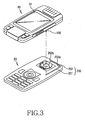
FIG. 3 is an exploded perspective view showing a configuration of a sliding/swing-type portable terminal capable of positioning a liquid crystal display at the center portion thereof according to the first exemplary embodiment of the present invention; -
FIG. 4 is a perspective view illustrating the sliding/swing-type portable terminal capable of positioning the liquid crystal display at the center portion thereof according to the first exemplary embodiment of the present invention, before the assembly of the sliding/swing-type portable terminal; -
FIG. 5 is a perspective view illustrating the sliding/swing-type portable terminal capable of positioning the liquid crystal display at the center portion thereof according to the first exemplary embodiment of the present invention, before the sliding movement of the portable terminal; -
FIG. 6 is a front view illustrating the sliding/swing-type portable terminal capable of positioning the liquid crystal display at the center portion thereof according to the first exemplary embodiment of the present invention, after the sliding movement of the portable terminal; -
FIG. 7 is a front view illustrating the sliding/swing-type portable terminal capable of positioning the liquid crystal display at the center portion thereof according to the first exemplary embodiment of the present invention, in which the portable terminal rotates; -
FIG. 8 is a front view illustrating the sliding/swing-type portable terminal capable of positioning the liquid crystal display at the center portion thereof according to the first exemplary embodiment of the present invention, in which the portable terminal rotates; -
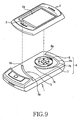
FIG. 9 is an exploded perspective view illustrating the configuration of a sliding/swing-type portable terminal capable of positioning a liquid crystal display at the center portion thereof according to the second exemplary embodiment of the present invention; -
FIG. 10 is a perspective view illustrating the sliding/swing-type portable terminal capable of positioning the liquid crystal display at the center portion thereof according to the second exemplary embodiment of the present invention; -
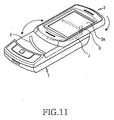
FIG. 11 is a perspective view illustrating the sliding/swing-type portable terminal capable of positioning the liquid crystal display at the center portion thereof according to the second exemplary embodiment of the present invention, in which a rotation housing rotates at an angle of 180 degrees; -
FIG. 12 is a front view illustrating the sliding/swing-type portable terminal capable of positioning the liquid crystal display at the center portion thereof according to the second exemplary embodiment of the present invention, in which the rotation housing rotates at an angle of 180 degrees; -
FIG. 13 is a front view illustrating the sliding/swing-type portable terminal capable of positioning the liquid crystal display at the center portion thereof according to the second exemplary embodiment of the present invention, in which the rotation housing rotates counterclockwise after rotation at an angle of 180 degrees; -
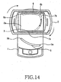
FIG. 14 is a front view illustrating the sliding/swing-type portable terminal capable of positioning the liquid crystal display at the center portion thereof according to the second exemplary embodiment of the present invention, in which the rotation housing rotates clockwise after rotation at an angle of 180 degrees; -
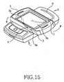
FIG. 15 is a perspective view illustrating the sliding/swing-type portable terminal capable of positioning the liquid crystal display at the center portion thereof according to the second exemplary embodiment of the present invention, before the rotation housing rotates; and -
FIG. 16 is a front view illustrating the sliding/swing-type portable terminal capable of positioning the liquid crystal display at the center portion thereof according to the second exemplary embodiment of the present invention, in which the rotation housing rotates clockwise. - Throughout the drawings, the same drawing reference numerals will be understood to refer to the same elements, features and structures.
- The matters defined in the description such as a detailed construction and elements are provided to assist in a comprehensive understanding of the embodiments of the invention. Accordingly, those of ordinary skill in the art will recognize that various changes and modifications of the embodiments described herein can be made without departing from the scope of the invention. Also, descriptions of well-known functions and constructions are omitted for clarity and conciseness.
- As illustrated in
FIGS. 3 and4 , a sliding/swing-typeportable terminal 10, according to a first exemplary embodiment of the present invention, includes abody housing 20, a slidinghousing 30 provided with a liquidcrystal display unit 31 and sliding and swinging on thebody housing 20 to be opened and closed, and a sliding/swing hinge device 40 to facilitate the sliding housing's 30 ability to slide. The sliding-type portable terminal capable of positioning the liquidcrystal display unit 31 at the center portion thereof is provided with aguide bar 100 and aguide member 200. Theguide bar 100 is provided on a rear surface of the slidinghousing 30 and inserted into theguide member 200 so as to slide and swing. Theguide member 200 is formed on the upper surface of thebody housing 20 in order to guide theguide bar 100 so that theguide bar 100 slides and rotates. Further, theguide member 200 guides the movement of theguide bar 100 when the slidinghousing 30 swings after the sliding movement of the slidinghousing 30. In addition, theguide member 200 guides the slidinghousing 30 so that the liquidcrystal display unit 31 of the sliding housing is positioned at the center portion of thebody housing 20. - As illustrated in
FIG. 5 , theguide bar 100 protrudes by a desired length so that theguide bar 100 is inserted into theguide member 200. - As illustrated in
FIGS. 6 and7 , theguide member 200 includes the first andsecond guide grooves first guide groove 201 is formed along a lengthwise direction of thebody housing 20 to guide the movement of theguide bar 100 toward a position at which the sliding movement of the slidinghousing 30 terminates. Thesecond guide groove 202 is formed at an end of thefirst guide groove 201 to be perpendicular to thefirst guide groove 201 so that theguide bar 100 moves along thesecond guide groove 202 when the slidinghousing 30 rotates after the sliding movement of the slidinghousing 30 terminates. - As illustrated in
FIG. 7 , thesecond guide groove 202 has thefirst stopper 202a provided at an end to stop the movement of theguide bar 100 at the termination position of the sliding movement, and thesecond stopper 202b provided at the other end to restrain the movement of theguide bar 100 at the termination position of the rotation. - As illustrated in
FIGS. 4 and6 , theguide bar 100 has a cylindrical shape which facilitates easy movement along the first andsecond guide grooves - As illustrated in
FIGS. 6 and7 , the first andsecond guide grooves second guide grooves guide bar 100. Thesecond guide groove 202 is formed to have a desired curvature to allow a smooth movement of theguide bar 100 when the slidinghousing 30 rotates. -
FIG. 8 shows a sliding/swing-typeportable terminal 10 according to another exemplary embodiment of the present invention, which can position a liquidcrystal display unit 31 at the center portion thereof. Referring toFIG. 8 , a sliding/swing hinge device 40 is eccentrically installed on a side of thebody housing 20. When the slidinghousing 30 rotates, the liquidcrystal display unit 31 of the slidinghousing 30 can be positioned at the center portion of thebody housing 20 by means of the eccentric hinge device. - The operation of the sliding/swing-type portable terminal according to the first exemplary embodiment of the present invention, which can position the liquid crystal display unit at the center portion thereof, will be described in detail with reference to
FIGS. 5 to 7 . - As illustrated in
FIGS. 3 and4 , the sliding/swing-type portable terminal includes theguide bar 100 and theguide member 200 in order to position the liquidcrystal display unit 31 at the center portion of thebody housing 20. - As illustrated in
FIGS. 4 and5 , theguide member 200 includes the first andsecond guide grooves housing 30 is assembled with thebody housing 20 while they face each other, theguide bar 100 is inserted into thefirst guide groove 201. - As illustrated in
FIG. 4 , theguide bar 100 protrudes by a desired length, and the first andsecond grooves - As illustrated in
FIG. 6 , when the slidinghousing 30 moves away from the body housing, theguide bar 100 moves along with the slidinghousing 30. According to an exemplary implementation, theguide bar 100 moves along thefirst guide groove 201. - When the sliding
housing 30 reaches the position of terminating the sliding movement thereof, theguide bar 100 stops the movement thereof once it makes contact with thefirst stopper 202a formed at one end of thesecond guide groove 202. - According to an exemplary implementation, as illustrated in
FIG. 7 , theguide bar 100 moves along with the slidinghousing 30 when the slidinghousing 30 rotates. Theguide bar 100 moves along thesecond guide groove 202. - Since the
second guide groove 202 is formed to have a desired curvature, theguide bar 100 can easily move along with the slidinghousing 30. - At this time, the
guide bar 100 makes contact with thesecond stopper 202b formed at the other end of thesecond guide groove 202 and stops its movement. - According to an exemplary implementation, the liquid
crystal display unit 31 of the slidinghousing 30 is positioned at the center portion of thebody housing 20. - The user can play a game or watch TV through the liquid
crystal display unit 31 positioned at the center portion of thebody housing 20. - The sliding/swing-type
portable terminal 10, according to another exemplary embodiment of the present invention, which can position the liquidcrystal display unit 31 at the center portion thereof, will be described. -
FIG. 8 illustrates the sliding/swing-type portable terminal capable of positioning the liquid crystal display unit at the center portion thereof. In the sliding/swing-type portable terminal, the sliding/swing hinge device 40 is eccentrically mounted on a side of thebody housing 20 to allow the slidinghousing 30 to rotate about a hinge axis of the eccentric hinge device. As a result, the liquidcrystal display unit 31 of the slidinghousing 30 is positioned at the center portion of thebody housing 20. - Since the sliding/
swing hinge device 40 is eccentrically mounted on a side of thebody housing 20 without the use of a separate device, it is possible to easily position the liquidcrystal display unit 31 of the sliding housing at the center portion of thebody housing 20. Further, it is possible to decrease the number of the parts and reduce manufacturing costs. The portable terminal may also be miniaturized because a separate installing space is unnecessary. - The operation of the swing-type portable terminal, according to the second exemplary embodiment of the present invention, which has the configuration as described above and can position the liquid crystal display unit at the center portion thereof, will be described in detail with reference to
FIGS. 9 to 16 . - As illustrated in
FIGS. 9 and10 , the swing-type portable terminal capable of positioning a liquidcrystal display unit 2a at the center portion thereof includes abody housing 1, aswing housing 2, aguide pin 3, and aguide member 4. - As illustrated in
FIGS. 11 and12 , theswing housing 2 is rotated by an angle of 180 degrees about a hinge axis Al extending perpendicularly to an upper surface of thebody housing 1 while facing thebody housing 1. - At this time, the
guide pin 3 provided to theswing housing 2 is movably received in theguide member 4. - According to an exemplary implementation, the
guide pin 3 includes a pogo pin. Theguide pin 3 is out of theguide member 4 when theswing housing 2 does not swing, while rotating along with theswing housing 2 and being inserted into theguide member 4 when theswing housing 2 rotates by an angle of 180 degrees. - The
guide member 4 includes first, second, andthird guide grooves - As illustrated in
FIG. 13 , thepogo pin 3 is inserted into the second andthird guide grooves swing housing 2 rotates counterclockwise, thepogo pin 3 rotates along with theswing housing 2 and moves along a predetermined trajectory to shift the central axis of theswing housing 2. Accordingly, the liquidcrystal display unit 2a provided on theswing housing 2 is positioned at the center portion of thebody housing 1. - The
pogo pin 3 of theswing housing 2 departs from thesecond stopper 6b, and simultaneously moves along a predetermined trajectory in thesecond guide groove 6 with a desired curvature. Thepogo pin 3 makes contact with thefirst stopper 6a formed at the other end of thesecond guide groove 6 and stops its movement. While theswing housing 2 swings, the central axis of theswing housing 2 moves so that the liquidcrystal display unit 2a of theswing housing 2 is positioned at the center portion of thebody housing 1. - According to an exemplary implementation, the user can play a game or watch TV through the liquid crystal display unit positioned at the center portion of the
body housing 1. - According to an exemplary implementation, when the
swing housing 2 ofFIG. 12 is swung clockwise again, theswing housing 2 returns to an initial position. Thepogo pin 3 departs from thefirst stopper 6a and makes contact with thesecond stopper 6b to stop its movement at a swing stopping position. - The
swing housing 2 rotates at an angle of 180 degrees and returns to the initial position. - In this state, as illustrated in
FIG. 14 , when theswing housing 2 rotates clockwise, thepogo pin 3 moves along with theswing housing 2 while moving along a predetermined trajectory in thethird guide groove 7 to shift the central axis of theswing housing 2. Accordingly, the liquidcrystal display unit 2a provided on theswing housing 2 can be positioned at the center portion of thebody housing 1. - The
pogo pin 3 of theswing housing 2 departs from thesecond stopper 7b formed in thethird guide groove 7 and simultaneously moves along a predetermined trajectory in thethird guide groove 7 with the desired curvature. Thepogo pin 3 makes contact with thefirst stopper 7a formed at the other end of thethird guide groove 3 and stops its movement. When theswing housing 2 rotates, the central axis of theswing housing 2 is simultaneously shifted so that the liquidcrystal display unit 2a of theswing housing 2 is positioned at the center portion of thebody housing 1. - According to an exemplary implementation, the user can play a game or watch TV through the liquid
crystal display unit 2a positioned at the center portion of the body housing. - As illustrated in
FIGs. 12 and14 , when theswing housing 2 rotates clockwise again and returns to the initial position, thepogo pin 3 departs from thefirst stopper 7a and makes contact with thesecond stopper 7b to stop its movement at the swing termination position. - The
swing housing 2 returns to the initial position by swinging by an angle of 180 degrees. - In this state, as illustrated
FIG. 10 , theswing housing 2 rotates by an angle of 180 degrees counterclockwise and faces thebody housing 1. - According to an exemplary implementation, the
pogo pin 3 moves along with theswing housing 2 and is inserted into thefirst guide groove 5. - As illustrated in
FIGS. 15 and16 , when theswing housing 2 rotates counterclockwise, thepogo pin 3 moves along with theswing housing 2 along a predetermined trajectory in thefirst guide groove 5, and thereby the central axis of theswing housing 2 is shifted. Accordingly, the liquidcrystal display device 2a provided on theswing housing 2 is positioned at the center portion of thebody housing 1. - According to an exemplary implementation, the
pogo pin 3 of theswing housing 2 departs from thesecond stopper 5b formed in thefirst guide groove 5 and simultaneously moves along a predetermined trajectory in theguide groove 5 having the desired curvature. Then, thepogo pin 3 makes contact with thefirst stopper 5a formed at the other end of thefirst guide groove 5 to stop its movement. When the swing housing moves, the central axis of theswing hinge 2 is shifted so that the liquidcrystal display unit 2a of theswing housing 2 rotates about the center portion of thebody housing 1. - According to an exemplary implementation, the user can play a game or watch TV through the liquid
crystal display unit 2a which is positioned at the center portion of thebody housing 1. - According to an exemplary implementation, when the
swing housing 2 rotates clockwise again and returns to the initial position, thepogo pin 3 departs from thefirst stopper 5a and makes contact with thesecond stopper 5b to stop its movement at the position of terminating its movement. - As illustrated in
FIG. 10 , theswing housing 2 returns to the initial position with facing thebody housing 1. - The present invention is applicable to all types of portable terminals.
- While the present invention has been shown and described with reference to certain exemplary embodiments thereof, it will be understood by those skilled in the art that various changes in form and details may be made therein without departing from the scope of the invention as defined by the appended claims and their equivalents.
Claims (9)
- A sliding/swing-type portable terminal (10) comprising:a body housing (20);a sliding housing (30) provided with a display unit (31), and sliding and swinging on the body housing to be opened and closed; anda sliding/swing hinge device (40) for allowing the sliding housing to slide and swing on the body housing, the sliding/swing hinge device comprising a guide bar (100) provided on the sliding housing and a guide member (200) provided to the body housing for guiding the sliding and swinging movement of the guide bar,wherein the guide member (200) comprises a first guide groove (201) for guiding the movement of the guide bar (100) to a termination position (202a) of the sliding housing, and a second guide groove (202) for guiding the movement of the guide bar when the sliding housing swings at the termination position (202a) of the sliding movement of the sliding housing,wherein the first and second guide grooves (201, 202) form a capital letter "L" shape, wherein one end of the second guide groove (202) is formed at an end of the first guide groove (201) to be perpendicular to the first guide groove, and the second guide groove (202) comprises a curvature formed as a portion of a semi-circular shape,wherein the guide member (200) guides the movement of the guide bar (100) to a termination position (202b) of the sliding movement of the sliding housing (30) so that the display unit (31) of the sliding housing is positioned at a center portion of the body housing (20) when the sliding housing (30) swings.
- The sliding/swing-type portable terminal as claimed in claim 1, wherein the guide bar (100) protrudes with a length corresponding to the guide member (200) to be guided therein.
- The sliding/swing-type portable terminal as claimed in claim 1, wherein a first stopper (202a) is provided to one end of the second guide groove (202) to stop the movement of the guide bar (100) at a position where the sliding movement of the sliding housing (30) terminates, and a second stopper (202b) is provided to the other end of the second guide groove (202) to stop the movement of the guide bar at a position where the swing movement of the sliding housing terminates.
- The sliding/swing-type portable terminal as claimed in claim 1, wherein the guide bar (100) comprises a cylindrical shape.
- The sliding/swing-type portable terminal as claimed in claim 1, wherein the first and second guide grooves (201, 202) respectively comprise an end semi-circularly formed.
- The sliding/swing-type portable terminal as claimed in claim 1, wherein the first guide groove (201) is formed in a longitudinal direction of the body housing (20).
- The sliding/swing-type portable terminal as claimed in claim 1, wherein the sliding/swing hinge device (40) is eccentrically mounted on the body housing (20).
- A method of using a sliding/swing-type portable terminal comprising:sliding and swinging a sliding housing (20) on a body housing (10);guiding the sliding and swinging movement of a guide bar (100);positioning a display unit (31) of the sliding housing at a center portion of the body housing when the sliding housing swings by a guide member (200); andguiding the movement of the guide bar in a first guide groove (201) to a termination position (202a) and guiding the movement of the guide bar in a second guide groove (202) when the sliding housing swings at the termination position (202a) of the sliding movement of the sliding housing,wherein the first and second guide grooves (201, 202) form a capital letter "L" shape, wherein one end of the second guide groove (202) is formed at an end of the first guide groove (201) to be perpendicular to the first guide groove, and the second guide groove (202) comprises a curvature formed as a portion of a semi-circular shape.
- The method of claim 8, wherein the guide bar (100) protrudes with a length corresponding to the guide member (200) to be guided therein.
Applications Claiming Priority (2)
| Application Number | Priority Date | Filing Date | Title |
|---|---|---|---|
| KR20060008477 | 2006-01-26 | ||
| KR1020060105686A KR100929076B1 (en) | 2006-01-26 | 2006-10-30 | Sliding / Rotating Type Portable Terminal that Centers LCD |
Publications (2)
| Publication Number | Publication Date |
|---|---|
| EP1814285A1 EP1814285A1 (en) | 2007-08-01 |
| EP1814285B1 true EP1814285B1 (en) | 2012-03-14 |
Family
ID=37963609
Family Applications (1)
| Application Number | Title | Priority Date | Filing Date |
|---|---|---|---|
| EP07001386A Ceased EP1814285B1 (en) | 2006-01-26 | 2007-01-23 | Sliding/swing-type portable terminal capable of positioning liquid crystal display at center portion thereof and method of using the same |
Country Status (3)
| Country | Link |
|---|---|
| US (1) | US20070171195A1 (en) |
| EP (1) | EP1814285B1 (en) |
| BR (1) | BRPI0700121A (en) |
Families Citing this family (8)
| Publication number | Priority date | Publication date | Assignee | Title |
|---|---|---|---|---|
| EP2109294A1 (en) * | 2008-04-07 | 2009-10-14 | Research In Motion Limited | Handheld electronic communication device transitionable between compact and expanded configurations |
| US7715191B2 (en) | 2008-04-07 | 2010-05-11 | Research In Motion Limited | Handheld electronic communication device transitionable between compact and expanded configurations |
| US20100245234A1 (en) * | 2009-03-31 | 2010-09-30 | Motorola, Inc. | Portable Electronic Device with Low Dexterity Requirement Input Means |
| JP2011049806A (en) * | 2009-08-27 | 2011-03-10 | Funai Electric Co Ltd | Mobile terminal |
| US8305747B2 (en) * | 2010-01-08 | 2012-11-06 | Shin Zu Shing Co., Ltd. | Rotary hinge and a portable electronic device with the same |
| CN102255986B (en) * | 2010-05-20 | 2014-04-30 | 深圳富泰宏精密工业有限公司 | Rotating mechanism and electronic device with rotating mechanism |
| US20120224302A1 (en) * | 2011-03-04 | 2012-09-06 | Albert Murray Pegg | Slidable and rotatable portable electronic device for aligning the surfaces of the keypad and display portions |
| CN111294427B (en) * | 2018-12-10 | 2021-07-27 | Oppo广东移动通信有限公司 | Electronic device |
Family Cites Families (10)
| Publication number | Priority date | Publication date | Assignee | Title |
|---|---|---|---|---|
| EP0883957B1 (en) * | 1996-02-26 | 2006-06-07 | Nokia Corporation | Radio telephone |
| KR100605862B1 (en) * | 2002-07-02 | 2006-07-31 | 삼성전자주식회사 | Sliding-type portable phone |
| JP3796222B2 (en) * | 2003-01-08 | 2006-07-12 | 三洋電機株式会社 | Portable wireless terminal |
| JP4192024B2 (en) * | 2003-04-17 | 2008-12-03 | 加藤電機株式会社 | Mounting device for portable terminal |
| US7529571B2 (en) * | 2003-09-03 | 2009-05-05 | Samsung Electronics Co., Ltd. | Sliding/hinge apparatus for sliding/rotating type mobile terminals |
| US7269450B2 (en) * | 2003-10-09 | 2007-09-11 | Samsung Electronics Co., Ltd. | Sliding/swing-type portable digital communication apparatus |
| KR100576000B1 (en) * | 2003-10-29 | 2006-05-02 | 삼성전자주식회사 | Spring module for sliding type portable terminal |
| US7280857B2 (en) * | 2004-06-25 | 2007-10-09 | Nokia Corporation | Mobile communications device having rotating display and camera |
| JP2006019925A (en) * | 2004-06-30 | 2006-01-19 | Sharp Corp | Portable information terminal, its switching operation method, and its displaying method |
| KR100575947B1 (en) * | 2004-09-17 | 2006-05-02 | 삼성전자주식회사 | Sliding swing device for mobile phone |
-
2006
- 2006-12-28 US US11/646,396 patent/US20070171195A1/en not_active Abandoned
-
2007
- 2007-01-23 EP EP07001386A patent/EP1814285B1/en not_active Ceased
- 2007-01-25 BR BRPI0700121-5A patent/BRPI0700121A/en not_active IP Right Cessation
Also Published As
| Publication number | Publication date |
|---|---|
| EP1814285A1 (en) | 2007-08-01 |
| US20070171195A1 (en) | 2007-07-26 |
| BRPI0700121A (en) | 2007-11-06 |
Similar Documents
| Publication | Publication Date | Title |
|---|---|---|
| EP1814285B1 (en) | Sliding/swing-type portable terminal capable of positioning liquid crystal display at center portion thereof and method of using the same | |
| EP1638295B1 (en) | Portable apparatus with slidable housing parts and a rotatable housing part | |
| EP1898606B1 (en) | Hinge device having a plurality of axes for a portable terminal and a connection member having the plurality of axes | |
| US7448872B2 (en) | Portable terminal having display unit cradled on a slant | |
| US7844050B2 (en) | Biaxial hinge device for mobile terminal and mounting mechanism thereof | |
| EP1758343A2 (en) | Hinge device for portable terminal and portable terminal having the same | |
| EP1610530A1 (en) | Dual-axis rotation folder-type portable apparatus | |
| US8380257B2 (en) | Swing-type mobile communication terminal and swing device thereof | |
| EP1806909B1 (en) | Portable communication terminal for games and user interfacing device thereof | |
| EP1843555B1 (en) | Slim portable terminal | |
| US7869840B2 (en) | Semi-automatic swing device for swing-type portable terminal | |
| EP1710986B1 (en) | Folder-type portable communication device having sliding display unit | |
| EP1746808B1 (en) | Sliding and swing portable terminal | |
| EP1906631A2 (en) | Semi-automatic sliding device for a portable terminal and portable terminal having the same | |
| EP1871079B1 (en) | Portable terminal with hinge stopper | |
| US20050124395A1 (en) | Portable communication apparatus and method thereof | |
| EP1755318A1 (en) | Hinge device for portable terminal | |
| KR20060086739A (en) | An opening and closing apparatus of a folder type mobile communication terminal thereof | |
| US20050245296A1 (en) | Portable dual hinge type communication device usable as personal digital assistant | |
| KR100849284B1 (en) | Dual rotation folder-type mobile phone and hinge unit thereof | |
| KR100678042B1 (en) | Portable digital communication device | |
| KR100790089B1 (en) | Mobile phone having stopper device | |
| KR20050080336A (en) | Portable digital communication device with improved grip | |
| KR100929076B1 (en) | Sliding / Rotating Type Portable Terminal that Centers LCD | |
| EP1887763B1 (en) | Dual-axis rotation folder-type mobile communication terminal and hinge device thereof |
Legal Events
| Date | Code | Title | Description |
|---|---|---|---|
| PUAI | Public reference made under article 153(3) epc to a published international application that has entered the european phase |
Free format text: ORIGINAL CODE: 0009012 |
|
| 17P | Request for examination filed |
Effective date: 20070123 |
|
| AK | Designated contracting states |
Kind code of ref document: A1 Designated state(s): AT BE BG CH CY CZ DE DK EE ES FI FR GB GR HU IE IS IT LI LT LU LV MC NL PL PT RO SE SI SK TR |
|
| AX | Request for extension of the european patent |
Extension state: AL BA HR MK RS |
|
| 17Q | First examination report despatched |
Effective date: 20080228 |
|
| AKX | Designation fees paid |
Designated state(s): DE FR GB |
|
| GRAP | Despatch of communication of intention to grant a patent |
Free format text: ORIGINAL CODE: EPIDOSNIGR1 |
|
| GRAS | Grant fee paid |
Free format text: ORIGINAL CODE: EPIDOSNIGR3 |
|
| GRAA | (expected) grant |
Free format text: ORIGINAL CODE: 0009210 |
|
| AK | Designated contracting states |
Kind code of ref document: B1 Designated state(s): DE FR GB |
|
| REG | Reference to a national code |
Ref country code: GB Ref legal event code: FG4D |
|
| REG | Reference to a national code |
Ref country code: DE Ref legal event code: R096 Ref document number: 602007021250 Country of ref document: DE Effective date: 20120510 |
|
| RAP2 | Party data changed (patent owner data changed or rights of a patent transferred) |
Owner name: SAMSUNG ELECTRONICS CO., LTD. |
|
| PLBE | No opposition filed within time limit |
Free format text: ORIGINAL CODE: 0009261 |
|
| STAA | Information on the status of an ep patent application or granted ep patent |
Free format text: STATUS: NO OPPOSITION FILED WITHIN TIME LIMIT |
|
| 26N | No opposition filed |
Effective date: 20121217 |
|
| REG | Reference to a national code |
Ref country code: DE Ref legal event code: R097 Ref document number: 602007021250 Country of ref document: DE Effective date: 20121217 |
|
| REG | Reference to a national code |
Ref country code: FR Ref legal event code: PLFP Year of fee payment: 10 |
|
| REG | Reference to a national code |
Ref country code: FR Ref legal event code: PLFP Year of fee payment: 11 |
|
| REG | Reference to a national code |
Ref country code: FR Ref legal event code: PLFP Year of fee payment: 12 |
|
| PGFP | Annual fee paid to national office [announced via postgrant information from national office to epo] |
Ref country code: GB Payment date: 20181220 Year of fee payment: 13 Ref country code: FR Payment date: 20181224 Year of fee payment: 13 |
|
| PGFP | Annual fee paid to national office [announced via postgrant information from national office to epo] |
Ref country code: DE Payment date: 20181219 Year of fee payment: 13 |
|
| REG | Reference to a national code |
Ref country code: DE Ref legal event code: R119 Ref document number: 602007021250 Country of ref document: DE |
|
| GBPC | Gb: european patent ceased through non-payment of renewal fee |
Effective date: 20200123 |
|
| PG25 | Lapsed in a contracting state [announced via postgrant information from national office to epo] |
Ref country code: DE Free format text: LAPSE BECAUSE OF NON-PAYMENT OF DUE FEES Effective date: 20200801 Ref country code: FR Free format text: LAPSE BECAUSE OF NON-PAYMENT OF DUE FEES Effective date: 20200131 Ref country code: GB Free format text: LAPSE BECAUSE OF NON-PAYMENT OF DUE FEES Effective date: 20200123 |