EP2168181B1 - Mischungen zur herstellung von photoaktiven schichten für organische solarzellen und organische photodetektoren - Google Patents
Mischungen zur herstellung von photoaktiven schichten für organische solarzellen und organische photodetektoren Download PDFInfo
- Publication number
- EP2168181B1 EP2168181B1 EP08785954.2A EP08785954A EP2168181B1 EP 2168181 B1 EP2168181 B1 EP 2168181B1 EP 08785954 A EP08785954 A EP 08785954A EP 2168181 B1 EP2168181 B1 EP 2168181B1
- Authority
- EP
- European Patent Office
- Prior art keywords
- alkyl
- aryl
- interrupted
- oxygen atoms
- cycloalkyl
- Prior art date
- Legal status (The legal status is an assumption and is not a legal conclusion. Google has not performed a legal analysis and makes no representation as to the accuracy of the status listed.)
- Active
Links
- 0 CC(*)(C=C1)C=CC(C(C2=CC)=O)=C1C2=* Chemical compound CC(*)(C=C1)C=CC(C(C2=CC)=O)=C1C2=* 0.000 description 5
Images


Classifications
-
- H—ELECTRICITY
- H10—SEMICONDUCTOR DEVICES; ELECTRIC SOLID-STATE DEVICES NOT OTHERWISE PROVIDED FOR
- H10K—ORGANIC ELECTRIC SOLID-STATE DEVICES
- H10K85/00—Organic materials used in the body or electrodes of devices covered by this subclass
- H10K85/20—Carbon compounds, e.g. carbon nanotubes or fullerenes
- H10K85/211—Fullerenes, e.g. C60
- H10K85/215—Fullerenes, e.g. C60 comprising substituents, e.g. PCBM
-
- B—PERFORMING OPERATIONS; TRANSPORTING
- B82—NANOTECHNOLOGY
- B82Y—SPECIFIC USES OR APPLICATIONS OF NANOSTRUCTURES; MEASUREMENT OR ANALYSIS OF NANOSTRUCTURES; MANUFACTURE OR TREATMENT OF NANOSTRUCTURES
- B82Y10/00—Nanotechnology for information processing, storage or transmission, e.g. quantum computing or single electron logic
-
- C—CHEMISTRY; METALLURGY
- C09—DYES; PAINTS; POLISHES; NATURAL RESINS; ADHESIVES; COMPOSITIONS NOT OTHERWISE PROVIDED FOR; APPLICATIONS OF MATERIALS NOT OTHERWISE PROVIDED FOR
- C09B—ORGANIC DYES OR CLOSELY-RELATED COMPOUNDS FOR PRODUCING DYES, e.g. PIGMENTS; MORDANTS; LAKES
- C09B23/00—Methine or polymethine dyes, e.g. cyanine dyes
- C09B23/02—Methine or polymethine dyes, e.g. cyanine dyes the polymethine chain containing an odd number of >CH- or >C[alkyl]- groups
- C09B23/04—Methine or polymethine dyes, e.g. cyanine dyes the polymethine chain containing an odd number of >CH- or >C[alkyl]- groups one >CH- group, e.g. cyanines, isocyanines, pseudocyanines
-
- C—CHEMISTRY; METALLURGY
- C09—DYES; PAINTS; POLISHES; NATURAL RESINS; ADHESIVES; COMPOSITIONS NOT OTHERWISE PROVIDED FOR; APPLICATIONS OF MATERIALS NOT OTHERWISE PROVIDED FOR
- C09B—ORGANIC DYES OR CLOSELY-RELATED COMPOUNDS FOR PRODUCING DYES, e.g. PIGMENTS; MORDANTS; LAKES
- C09B23/00—Methine or polymethine dyes, e.g. cyanine dyes
- C09B23/10—The polymethine chain containing an even number of >CH- groups
- C09B23/105—The polymethine chain containing an even number of >CH- groups two >CH- groups
-
- H—ELECTRICITY
- H10—SEMICONDUCTOR DEVICES; ELECTRIC SOLID-STATE DEVICES NOT OTHERWISE PROVIDED FOR
- H10K—ORGANIC ELECTRIC SOLID-STATE DEVICES
- H10K30/00—Organic devices sensitive to infrared radiation, light, electromagnetic radiation of shorter wavelength or corpuscular radiation
- H10K30/30—Organic devices sensitive to infrared radiation, light, electromagnetic radiation of shorter wavelength or corpuscular radiation comprising bulk heterojunctions, e.g. interpenetrating networks of donor and acceptor material domains
-
- H—ELECTRICITY
- H10—SEMICONDUCTOR DEVICES; ELECTRIC SOLID-STATE DEVICES NOT OTHERWISE PROVIDED FOR
- H10K—ORGANIC ELECTRIC SOLID-STATE DEVICES
- H10K85/00—Organic materials used in the body or electrodes of devices covered by this subclass
- H10K85/60—Organic compounds having low molecular weight
- H10K85/649—Aromatic compounds comprising a hetero atom
- H10K85/652—Cyanine dyes
-
- H—ELECTRICITY
- H10—SEMICONDUCTOR DEVICES; ELECTRIC SOLID-STATE DEVICES NOT OTHERWISE PROVIDED FOR
- H10K—ORGANIC ELECTRIC SOLID-STATE DEVICES
- H10K30/00—Organic devices sensitive to infrared radiation, light, electromagnetic radiation of shorter wavelength or corpuscular radiation
- H10K30/50—Photovoltaic [PV] devices
-
- Y—GENERAL TAGGING OF NEW TECHNOLOGICAL DEVELOPMENTS; GENERAL TAGGING OF CROSS-SECTIONAL TECHNOLOGIES SPANNING OVER SEVERAL SECTIONS OF THE IPC; TECHNICAL SUBJECTS COVERED BY FORMER USPC CROSS-REFERENCE ART COLLECTIONS [XRACs] AND DIGESTS
- Y02—TECHNOLOGIES OR APPLICATIONS FOR MITIGATION OR ADAPTATION AGAINST CLIMATE CHANGE
- Y02E—REDUCTION OF GREENHOUSE GAS [GHG] EMISSIONS, RELATED TO ENERGY GENERATION, TRANSMISSION OR DISTRIBUTION
- Y02E10/00—Energy generation through renewable energy sources
- Y02E10/50—Photovoltaic [PV] energy
- Y02E10/549—Organic PV cells
Definitions
- the present invention relates to the use of mixtures which contain compounds DA in which D stands for a donor and A for an acceptor grouping, in particular the use of mixtures which contain compounds DA and fullerene derivatives for the production of photoactive layers for organic Solar cells and organic photodetectors, corresponding organic solar cells and organic photodetectors, as well as mixtures containing compounds DA and fullerene derivatives.
- organic semiconductors based on low molecular weight or polymeric materials will also be increasingly used. These often have advantages over classic inorganic semiconductors, for example better substrate compatibility and better processability of the semiconductor components based on them. They allow processing on flexible substrates and allow their frontier orbital energies to be precisely adapted to the respective area of application using the methods of molecular modeling. The significantly reduced costs of such components have brought a renaissance to the research field of organic electronics.
- Organic Electronics focuses on the development of new materials and manufacturing processes for the manufacture of electronic components based on organic semiconductor layers. These include above all organic field-effect transistors (OFET) as well as organic light-emitting diodes (OLED; e.g. for use in displays) and organic photovoltaics.
- the direct conversion of solar energy into electrical energy in solar cells is based on the internal photo effect of a semiconductor material, i.e. the generation of electron-hole pairs through the absorption of photons and the separation of the negative and positive charge carriers at a p-n junction or a Schottky contact.
- the photovoltage generated in this way can cause a photocurrent in an external circuit, through which the solar cell emits its power.
- the semiconductor can only absorb photons with an energy greater than its band gap.
- the size of the semiconductor band gap therefore determines the proportion of sunlight that can be converted into electrical energy.
- organic solar cells will outperform classic silicon-based solar cells due to lower costs, lower weight, the possibility of producing flexible and / or colored cells, and the better possibility of fine-tuning the band gap. So there is a big one Demand for organic semiconductors that are suitable for the production of organic solar cells.
- organic solar cells In order to use solar energy as effectively as possible, organic solar cells usually consist of two absorbing materials with different electron affinities or different ionization behavior. One material then acts as a p-conductor (electron donor), the other as an n-conductor (electron acceptor).
- the first organic solar cells consisted of a two-layer system of a copper phthalocyanine as the p-conductor and PTCBI as the n-conductor and showed an efficiency of 1%.
- relatively high layer thicknesses are used (e.g. 100 nm).
- the excited state created by the absorbed photons must reach a p-n junction ("p-n junction") to create a hole and an electron which then flows to the anode and cathode.
- p-n junction p-n junction
- the photoactive layer here contains the acceptor and donor compound (s) as a bicontinuous phase.
- acceptor and donor compound s
- a rapid charge separation takes place compared to other relaxation processes and the holes and electrons that are created are removed via the corresponding electrodes.
- Additional layers, such as hole or electron transport layers, are often applied between the electrodes and the photoactive layer in order to increase the efficiency of such cells.
- polymers such as polyvinylphenylenes or polythiophenes or dyes from the class of phthalocyanines, such as Zn or vanadyl phthalocyanine, and fullerene and fullerene derivatives and various perylenes have been used as donor materials in such bulk heterojunction cells.
- phthalocyanines such as Zn or vanadyl phthalocyanine
- fullerene and fullerene derivatives and various perylenes have been used as donor materials in such bulk heterojunction cells.
- Photoactive layers of the donor / acceptor pairs poly (3-hexyl-thiophene) (“P3HT”) / [6,6] -phenyl-C 61 -butylic acid methyl ester (“PCBM”), poly (2- methoxy-5- (3,7-dimethyloctyloxy) -1,4-phenylenevinylene) (“OC 1 C 10 -PPV”) / PCBM and Zn-phthalocyanine / fullerene investigated.
- P3HT poly (3-hexyl-thiophene)
- PCBM poly (2- methoxy-5- (3,7-dimethyloctyloxy) -1,4-phenylenevinylene
- Yamanari T. et al. (“Dye-sensitized Bulk Heterojunction Polymer Solar Cells", Conference Record of the 2006 IEEE 4th World Conference on Photovoltaic Energy Conversion (IEEE CAT. NO. 06CH37747) IEEE PISCATAWAY, NJ, USA, 2006, page 4 pp., XP002500718 ) discloses organic solar cells based on poly (3-hexylthiophenes) (P3HT) and [6,6] -phenyl-C61-butyric acid methyl ester (PCBM).
- P3HT poly (3-hexylthiophenes)
- PCBM [6,6] -phenyl-C61-butyric acid methyl ester
- EP 0 901 175 A2 discloses a photoelectric conversion device having a layer of dye sensitized nanoparticulate semiconductor and a hole transport layer containing an organic hole transport agent.
- WO 2006/092135 A1 discloses a photoactive component with organic layers, in particular a solar cell, with a layer arrangement which has an electrode and a counter-electrode as well as a sequence of organic layers which is arranged between the electrode and the counter-electrode.
- the object of the present invention was now to provide further photoactive layers for use in electronic components, in particular in organic solar cells and organic photodetectors, which can be easily produced
- Halogen denotes fluorine, chlorine, bromine and iodine, especially fluorine and chlorine.
- C 1 -C 10 -alkyl is linear or branched alkyl, for example methyl, ethyl, n-propyl, isopropyl, n-butyl, isobutyl, sec-butyl, tert-butyl, n-pentyl, n-hexyl, n -Heptyl, n-octyl, 2-ethylhexyl, n-nonyl and n-decyl.
- Preferred groups are methyl, isopropyl, n-butyl, tert-butyl and 2-ethylhexyl; in the radicals mentioned, one or more hydrogen atoms can optionally be replaced by fluorine atoms, so that these radicals can also be partially fluorinated or perfluorinated.
- C 1 -C 10 -alkyl which is interrupted by one or two non-adjacent oxygen atoms is, for example, 3-methoxyethyl, 2- and 3-methoxypropyl, 2-ethoxyethyl, 2- and 3-ethoxypropyl, 2-propoxyethyl, 2- and 3-propoxypropyl, 2-butoxyethyl, 2- and 3-butoxypropyl, 3,6-dioxaheptoyl and 3,6-dioxaoctyl should be mentioned.
- the C 1 -C 10 alkoxy, C 1 -C 10 alkylamino, di (C 1 -C 10 alkyl) amino, C 1 -C 10 alkylamino-sulfonylamino, di (C 1 -C 10 -alkyl) aminosulfonylamino and C 1 -C 10 -alkylsulfonylamino radicals are derived correspondingly from the aforementioned C 1 -C 10 -alkyl radicals, in the case of the di (C 1 -C 10 -alkyl) amino groups both identical as well as different C 1 -C 10 -alkyl radicals can be located on the amino group.
- Examples include methoxy, ethoxy, n-propoxy, isopropoxy, n-butoxy, isobutoxy, sec-butoxy, tert-butoxy, n-pentoxy, n-hexoxy, n-heptoxy, n-octoxy, 2-ethylhexoxy, n-Nonoxy and n-Decoxy, methylamino, ethylamino, n-propylamino, isopropylamino, n-butylamino, isobutylamino, sec.-butylamino, tert.-butylamino, n-pentylamino, n-hexylamino, n-heptylamino, n-octylamino, 2-Ethylhexylamino, n-nonylamino and n-decylamino, dimethylamino, diethylamino, di (n
- C 5 -C 7 cycloalkyl is to be understood as meaning, in particular, cyclopentyl, cyclohexyl and cycloheptyl.
- Aryl encompasses mono- or polynuclear aromatic hydrocarbon radicals which can be unsubstituted or substituted.
- Aryl preferably represents phenyl, tolyl, xylyl, mesityl, duryl, naphthyl, fluorenyl, anthracenyl, phenanthrenyl or naphthyl, particularly preferably phenyl or naphthyl, these aryl groups in the case of substitution generally 1, 2, 3, 4 or 5, can preferably carry 1, 2 or 3 substituents selected from the group consisting of C 1 -C 10 -alkyl, C 1 -C 10 -alkoxy, cyano, nitro, SO 2 NR a R b , NHSO 2 NR a R b , CONR a R b and CO 2 R a , where the C 1 -C 10 -alkoxy groups are derived from the C 1 -C 10 -alkyl groups listed above.
- R a and R b
- aryl-C 1 -C 10 -alkyl and aryloxy-C 1 -C 10 -alkyl groups are derived from the alkyl and aryl groups listed above by formal replacement of a hydrogen atom of the linear or branched alkyl chain with an aryl or aryloxy group.
- Preferred groups here are benzyl and linear aryloxy-C 1 -C 10 -alkyl, the aryloxy radical preferably being terminally bonded in the case of C 2 -C 10 -alkyl radicals.
- component K1 can take on the role of electron donor, and component K2 then takes on the role of electron acceptor. Alternatively, however, component K1 can also assume the role of electron acceptor, and component K2 then functions as an electron donor.
- the way in which the respective component works depends on the energy of the HOMO or LUMO of component K1 in relation to the energy of the HOMO or LUMO of component K2.
- the compounds of component K1, in particular the compounds with the preferred donor groups D01 to D14 and acceptor groups A01 to A09 listed above, are typically merocyanines, which usually appear as electron donors. This is particularly the case when rylene or fullerene derivatives are used as component K2, which then usually act as electron acceptors.
- component K2 can also obey the structural definition of component K1, so that one compound of the formula D-A can assume the role of the electron donor and another compound of the formula D-A can assume the role of the electron acceptor.
- Mixtures according to the invention are preferably used in which the compounds of the general formula k1 or the preferred compounds in which the donor groups D and / or the acceptor compounds A have the previously listed meaning of the groups D01 to D14 or A01 to 09 each have a molecular weight of have a maximum of 1,000 g / mol, in particular a maximum of 600 g / mol.
- component K2 is one or more fullerenes and / or fullerene derivatives.
- fullerenes that may be mentioned are C 60 , C 70 , C 76 , C 80 , C 82 , C 84 , C 86 , C 90 and C 94 , in particular C 60 and C 70 .
- the fullerene derivatives are usually obtained by reaction at one or more of the carbon-carbon double bonds contained in the fullerenes, the character of the fullerene unit in the resulting derivatives essentially not being changed.
- C 1 -C 10 -alkylene is to be understood as meaning, in particular, a linear chain - (CH 2 ) n -, where n is 1, 2, 3, 4, 5, 6, 7, 8, 9 or 10.
- R 520 denotes a C 1 -C 4 alkyl, in particular a methyl radical
- A denotes a propylene chain - (CH 2 ) 3 -
- R 510 denotes an optionally substituted phenyl or 2-thienyl.
- the fullerene derivative is preferably methyl [6,6] -phenyl-C 61 -butylate (“PCBM”).
- the isomeric compounds of the formula k1 or the isomers of the corresponding preferred are accordingly also intended and particularly preferred compounds and mixtures of isomers may be included.
- Mixtures are preferably used according to the invention, which are characterized in that component K1 is present in a proportion of 10 to 90% by mass and component K2 is present in a proportion of 90 to 10% by mass, the proportions of components K1 and K2 being , each based on the total mass of components K1 and K2, add 100% by mass.
- Particularly preferred use is found in mixtures which are characterized in that component K1 is present in a proportion of 20 to 80% by mass and component K2 is present in a proportion of 80 to 20% by mass, the proportions of components K1 and K2 being , each based on the total mass of components K1 and K2, again add 100% by mass.
- organic solar cells and organic photodetectors which contain photoactive layers which have been produced using the mixtures containing components K1 and K2 described above, or using the preferred embodiments of the mixtures also described above.
- Organic solar cells are usually built up in layers and generally comprise at least the following layers: electrode, photoactive layer and counter electrode. These layers are usually located on a substrate that is customary for this purpose. Suitable substrates are, for example, oxidic materials such as glass, quartz, ceramic, SiO 2 , etc., polymers such as polyvinyl chloride, polyolefins, e.g. polyethylene and polypropylene, polyesters, fluoropolymers, polyamides, polyurethanes, polyalkyl (meth) acrylates, Polystyrene and mixtures and composites thereof, and combinations of the substrates listed above.
- oxidic materials such as glass, quartz, ceramic, SiO 2 , etc.
- polymers such as polyvinyl chloride, polyolefins, e.g. polyethylene and polypropylene, polyesters, fluoropolymers, polyamides, polyurethanes, polyalkyl (meth) acrylates, Polystyrene and mixtures
- Particularly suitable materials for one electrode are metals, such as the alkali metals Li, Na, K, Rb and Cs, the alkaline earth metals Mg, Ca and Ba, Pt, Au, Ag, Cu, Al, In, metal alloys, for example based Pt, Au, Ag, Cu, etc. and special Mg / Ag alloys, but also alkali metal fluorides, such as LiF, NaF, KF, RbF and CsF, and mixtures of alkali metal fluorides and alkali metals.
- a material that essentially reflects the incident light is preferably used as the electrode.
- These include, for example, metal films made of Al, Ag, Au, In, Mg, Mg / Al, Ca, etc.
- the counter electrode consists of a material that is essentially transparent to incident light, for example ITO, doped ITO, ZnO, TiO 2 , Cu, Ag, Au and Pt, the latter metals being present in correspondingly thin layers.
- An electrode / counter-electrode is to be regarded as "transparent” if at least 50% of the radiation intensity is transmitted in the wavelength range in which the photoactive layer absorbs radiation. In the case of several photoactive layers, an electrode / counter electrode should be regarded as "transparent” if at least 50% of the radiation intensity is transmitted in the wavelength ranges in which the photoactive layers absorb radiation.
- one or more further layers can be present in the organic solar cells and photodetectors according to the invention, for example electron transporting layers ("ETL”) and / or hole transporting layers (“HTL”) and / or blocking layers, for example exciton blocking layers (“EBL", excition blocking layers), which usually do not absorb the incident light, or layers which serve as charge transport layers and at the same time improve the contact to one or both electrodes of the solar cell.
- ETL and HTL can also be doped, so that cells of the pin type result, as they are, for example, in the publication by J. Drechsel et al., Thin Solid Films 451-452 (2004), 515-517 , are described.
- organic solar cells are also, for example, in the writings WO 2004/083958 A2 , US 2005/0098726 A1 and US 2005/0224905 A1 which is hereby incorporated by reference in its entirety.
- Photodetectors essentially have a structure analogous to organic solar cells, but they are operated with a suitable bias voltage, which generates a corresponding current flow as a measurement response when exposed to radiation energy.
- the photoactive layers are processed, for example, from solution.
- components K1 and K2 can already be dissolved together, but they can also be present separately as a solution of component K1 and a solution of component K2, the mixing of the corresponding solutions in the latter case taking place shortly before application to the layer below.
- concentrations of components K1 and K2 are generally around a few g / l to a few tens of g / l solvent.
- Suitable solvents are all liquids which evaporate without leaving any residue and have sufficient solubility for components K1 and K2.
- aromatic compounds such as benzene, toluene, xylene, mesitylene, chlorobenzene or dichlorobenzene, trialkylamines, nitrogen-containing heterocycles, N, N-disubstituted aliphatic carboxamides such as dimethylformamide, diethylformamide, dimethylacetamide or dimethylbutyramide, N, N-disubstituted for example N-methylpyrrolidone, linear and cyclic ketones such as methyl ethyl ketone, cyclopentanone or cyclohexanone, cyclic ethers such as tetrahydrofuran, or alcohols such as methanol, ethanol, propanol, isopropanol or butanol.
- Suitable methods for applying the photoactive layers according to the invention from the liquid phase are known to the person skilled in the art. Processing by means of spin coating is particularly advantageous here, since the thickness of the photoactive layer can be controlled in a simple manner by the amount and / or concentration of the solution used and the speed of rotation and / or duration of rotation.
- the solution is usually processed at room temperature.
- processing from the gas phase is also possible, in particular by vacuum sublimation.
- such mixtures according to the invention are claimed which are characterized in that component K1 in a proportion of 10 to 90% by mass and component K2 in a proportion of 90 to 10% by mass is present, the proportions of components K1 and K2, each based on the total mass of components K1 and K2, adding up to 100% by mass.
- such mixtures according to the invention are claimed which are characterized in that component K1 is present in a proportion of 20 to 80% by mass and component K2 in a proportion of 80 to 20% by mass , the proportions of components K1 and K2, each based on the total mass of components K1 and K2, adding up to 100% by mass.
- the layers are usually applied in the order (2) or (3) to (6).
- the transparent electrode (2) is already applied to the glass substrate (1).
- Transparent substrate Glass plate
- Transparent electrode 140 nm
- Hole injection layer 0 - 100 nm
- Photoactive layer 30 - 500 nm
- metal electrode 0-200 nm (6)
- Encapsulation optional for experimental setup (1) + (2): Transparent substrate and transparent electrode
- ITO indium tin oxide
- the aqueous suspension BAYTRON P VP I4083 from H. C. Stark was used to improve the surface properties and the hole injection of the ITO anode.
- the suspension also contains the polymer poly (styrenesulfonic acid) (PSSH).
- PSSH polymer poly (styrenesulfonic acid)
- the PEDOT layer thickness was approx. 35 nm. After spin-coating, the PEDOT layers were baked for two minutes at 110 ° C. in order to remove residual water.
- the solutions of the individual components were made up in a concentration of 20 g / L shortly before the layer was produced and stirred at 50 to 70 ° C. overnight.
- the solutions of the individual components were combined and mixed well immediately before the paint was spun.
- the layer thicknesses were mainly determined by the speed of rotation and less controlled over the rotation time. The rotation speed was varied in the range from 450 to 2200 rpm, the rotation times were between 20 and 40 seconds.
- top electrode For the vapor deposition of the metal electrode (so-called “top electrode” since it represents the last active layer in the structure before the encapsulation layer), aluminum, barium and silver in granulate form with a purity of 99.9% were used.
- the top electrode was evaporated under a high vacuum of at least 5 x 10 -6 hPa, the evaporation rate initially being kept low (0.2 to 0.5 nm / s) and only with increasing layer thickness to 1.0 to 1.5 nm / s was increased.
- the vapor-deposited aluminum layers had a thickness of about 150 nm.
- Figures 3a to 3d Representation of the dependence of the relative parameters of ATOP7: PCBM solar cells with a mass ratio for ATOP7: PCBM of 3: 7 on the tempering time t (in min).
- the relative parameters were determined by forming the ratio of the respective parameter after t min tempering to the starting value of the parameter without tempering.
- the heat treatments were carried out at 95 ° C and 125 ° C.
- the characteristics of the cells can be improved somewhat by tempering the layers (after the electrodes have been deposited).
- the component K1 ie the one or more merocyanines of the formula k1
- the component K2 ie the fullerene derivative
- organic solar cells were produced in which the photoactive layer consisted of the compound ATOP4 as component K1 and the compound poly (3-hexyl-thiophene) ("P3HT") as component K2, the latter compound usually being an electron donor.
- the mass fraction of ATOP4 to P3HT was varied in the range 1: 3, 1: 1 and 3: 1.
- the corresponding efficiencies ⁇ were found to be 0.02%, 0.03% and 0%. It was found that P3HT in this combination again functions as an electron donor, while ATOP4 functions as an electron acceptor.
Landscapes
- Chemical & Material Sciences (AREA)
- Engineering & Computer Science (AREA)
- Physics & Mathematics (AREA)
- Nanotechnology (AREA)
- Organic Chemistry (AREA)
- Materials Engineering (AREA)
- Electromagnetism (AREA)
- Mathematical Physics (AREA)
- Theoretical Computer Science (AREA)
- Crystallography & Structural Chemistry (AREA)
- Spectroscopy & Molecular Physics (AREA)
- Photovoltaic Devices (AREA)
- Organic Low-Molecular-Weight Compounds And Preparation Thereof (AREA)
- Plural Heterocyclic Compounds (AREA)
- Indole Compounds (AREA)
Description
- Die vorliegende Erfindung betrifft die Verwendung von Mischungen, welche Verbindungen D-A enthalten, in welchen D für eine Donor- und A für eine Akzeptorgruppierung steht, insbesondere die Verwendung von Mischungen, welche Verbindungen D-A und Fulleren-Derivate enthalten, zur Herstellung von photoaktiven Schichten für organische Solarzellen und organische Photodetektoren, entsprechende organische Solarzellen und organische Photodetektoren, sowie Mischungen, welche Verbindungen D-A und Fulleren-Derivate enthalten.
- Es wird erwartet, dass zukünftig in vielen Bereichen der Elektronikindustrie neben den klassischen anorganischen Halbleitern zunehmend auch organische Halbleiter auf Basis von niedermolekularen oder polymeren Materialien eingesetzt werden. Diese weisen vielfach Vorteile gegenüber den klassischen anorganischen Halbleitern auf, beispielsweise eine bessere Substratkompatibilität und eine bessere Verarbeitbarkeit der auf ihnen basierenden Halbleiterbauteile. Sie erlauben die Verarbeitung auf flexiblen Substraten und ermöglichen es, ihre Grenzorbitalenergien mit den Methoden des Molecular Modellings auf den jeweiligen Anwendungsbereich genau anzupassen. Die deutlich verringerten Kosten derartiger Bauteile haben dem Forschungsgebiet der organischen Elektronik eine Renaissance gebracht. Die "Organische Elektronik" beschäftigt sich schwerpunktmäßig mit der Entwicklung neuer Materialien und Fertigungsprozesse für die Herstellung elektronischer Bauelemente auf der Basis organischer Halbleiterschichten. Dazu zählen vor allem organische Feldeffekttransistoren (Organic Field-Effect Transistors, OFET) sowie organische Leuchtdioden (Organic Light Emitting Diodes, OLED; z.B. für den Einsatz in Displays) und die organische Photovoltaik.
- Die Direktumwandlung von Solarenergie in elektrische Energie in Solarzellen beruht auf dem inneren Photoeffekt eines Halbleitermaterials, d.h. der Erzeugung von Elektron-Loch-Paaren durch Absorption von Photonen und der Trennung der negativen und positiven Ladungsträger an einem p-n-Übergang oder einem Schottky-Kontakt. Die so erzeugte Photospannung kann in einem äußeren Stromkreis einen Photostrom bewirken, durch den die Solarzelle ihre Leistung abgibt.
- Vom Halbleiter können dabei nur solche Photonen absorbiert werden, die eine Energie aufweisen, die größer als seine Bandlücke ist. Die Größe der Halbleiterbandlücke bestimmt also den Anteil des Sonnenlichts, der in elektrische Energie umgewandelt werden kann. Es wird zukünftig erwartet, dass organische Solarzellen die klassischen Solarzellen auf Siliziumbasis aufgrund geringerer Kosten, eines geringeren Gewichts, der Möglichkeit zur Herstellung flexibler und/oder farbiger Zellen, der besseren Möglichkeit zur Feinabstimmung des Bandabstands übertreffen werden. Es besteht somit ein großer Bedarf an organischen Halbleitern, die sich zur Herstellung organischer Solarzellen eignen.
- Um die Sonnenenergie möglichst effektiv zu nutzen bestehen organische Solarzellen normalerweise aus zwei absorbierenden Materialien mit unterschiedlicher Elektronenaffinität bzw. unterschiedlichem Ionisationsverhalten. Das eine Material wirkt dann als p-Leiter (Elektronendonor), das andere als n-Leiter (Elektronenakzeptor). Die ersten organischen Solarzellen bestanden aus einem zweilagigen System aus einem KupferPhthalocyanin als p-Leiter und PTCBI als n-Leiter und zeigten einen Wirkungsgrad von 1%. Um möglichst alle auftreffenden Photonen zu nutzen, werden relativ hohe Schichtdicken eingesetzt (z.B. 100 nm). Um Strom zu erzeugen, muss der durch die absorbierten Photonen erzeugte angeregte Zustand jedoch eine p-n-Grenzschicht ("p-n-junction") erreichen, um ein Loch und ein Elektron zu erzeugen, welches dann zur Anode und Kathode fließt. Die meisten organischen Halbleiter haben jedoch nur Diffusionslängen für den angeregten Zustand von bis zu 10 nm. Selbst durch die besten bisher bekannten Herstellverfahren kann die Distanz, über die der angeregte Zustand weitergeleitet werden muss, auf minimal 10 bis 30 nm verringert werden.
- Neuere Entwicklungen in der organischen Photovoltaik gehen in die Richtung der sogenannten "Bulk-Heterojunction": die photoaktive Schicht enthält hierbei die Akzeptor- und Donorverbindung(en) als bikontinuierliche Phase. Durch photoinduzierten Ladungstransfer vom angeregten Zustand der Donorverbindung zur Akzeptorverbindung findet aufgrund der räumlichen Nähe der Verbindungen eine, verglichen mit anderen Relaxationsvorgängen, schnelle Ladungstrennung statt und die entstandenen Löcher und Elektronen werden über die entsprechende Elektroden abgeführt. Zwischen die Elektroden und die photoaktive Schicht werden oftmals weitere Schichten, wie z.B. Löcher- oder Elektronentransportschichten, aufgebracht, um die Effizienz solcher Zellen zu erhöhen.
- Bislang werden als Donormaterialien in solchen Bulk-Heterojunction-Zellen meist Polymere, wie z.B. Polyvinylphenylene oder Polythiophene, oder Farbstoffe aus der Klasse der Phthalocyanine, z.B. Zn- oder Vanadylphthalocyanin, und als Akzeptormaterialien Fulleren und Fulleren-Derivate sowie verschiedene Perylene verwendet. Intensiv wurden und werden photoaktive Schichten aus den Donor-/Akzeptor-Paaren Poly(3-hexyl-thiophen) ("P3HT")/ [6,6]-Phenyl-C61-butylsäuremethylester ("PCBM"), Poly(2-methoxy-5-(3,7-dimethyloctyloxy)-1,4-phenylenvinylen)("OC1C10-PPV")/PCBM und Zn-Phthalocyanin/Fulleren untersucht.
- Yamanari T. et al. ("Dye-sensitized Bulk Heterojunction Polymer Solar Cells", Conference Record of the 2006 IEEE 4th World Conference on Photovoltaic Energy Conversion (IEEE CAT. NO. 06CH37747) IEEE PISCATAWAY, NJ, USA, 2006, Seite 4 pp., XP002500718) offenbart organische Solarzellen basierend auf Poly(3-Hexylthiophene) (P3HT) und [6,6]-Phenyl-C61-Buttersäuremethylester (PCBM).
-
EP 0 901 175 A2 offenbart eine photoelektrische Umwandlungsvorrichtung mit einer Schicht aus farbstoffsensibilisiertem nanopartikulärem Halbleiter und einer Lochtransportschicht, die ein organisches Lochtransportmittel enthält. -
WO 2006/092135 A1 offenbart ein photoaktives Bauelement mit organischen Schichten, insbesondere eine Solarzelle, mit einer Schichtanordnung, welche eine Elektrode und eine Gegenelektrode sowie eine Folge organischer Schichten aufweist, die zwischen der Elektrode und der Gegenelektrode angeordnet ist. - Aufgabe der vorliegenden Erfindung war es nun, weitere photoaktive Schichten zur Verwendung in elektronischen Bauelementen, insbesondere in organischen Solarzellen und organischen Photodetektoren, bereitzustellen, welche leicht herstellbar sind
- und für die Umwandlung von Lichtenergie in elektrische Energie in technischen Anwendungen einen ausreichenden Wirkungsgrad aufweisen.
- Dementsprechend wurden die Verwendung von Mischungen, welche als Komponenten enthalten
- K1) ein oder mehrere Verbindungen der allgemeinen Formel k1
D-A (k1)
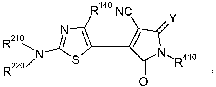
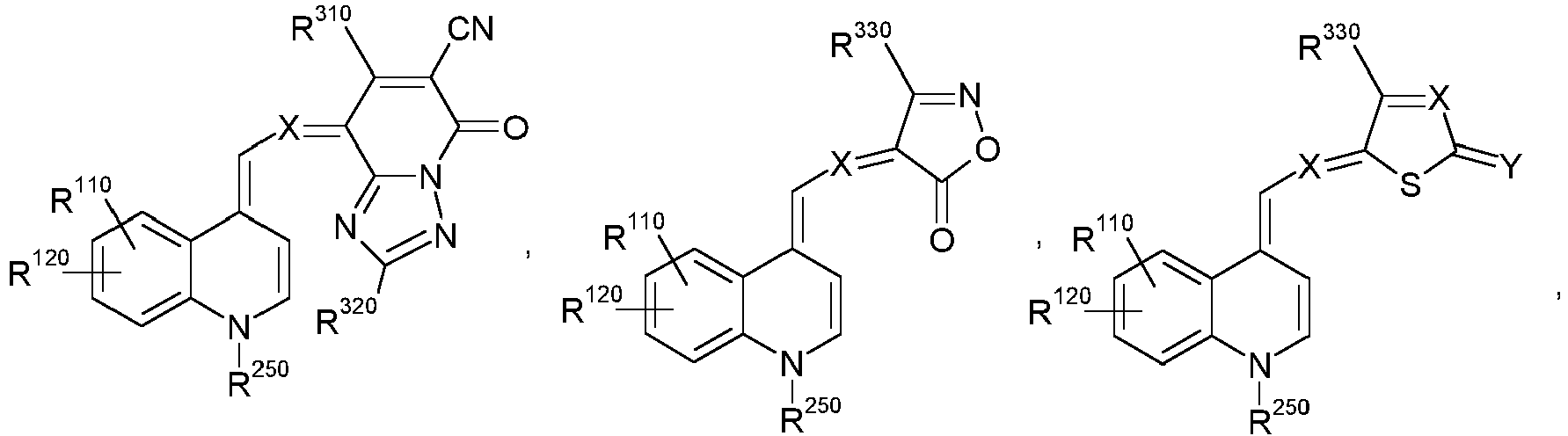
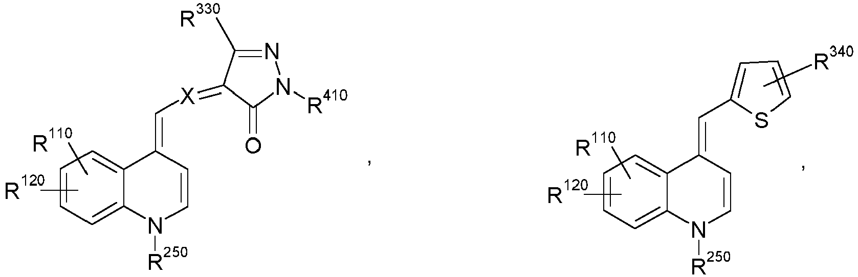
als Elektronendonor bzw. Elektronenakzeptor, worin bedeuten - D eine Donorgruppierung, welche mindestens eine Kohlenstoff-Kohlenstoff- oder Kohlenstoff-Heteroatom-Doppelbindung und mindestens einen, gegebenenfalls anellierten carbo- oder heterocyclischen Ring enthält,
- A eine Akzeptorgruppierung, welche mindestens eine Kohlenstoff-Kohlenstoff- oder Kohlenstoff-Heteroatom-Doppelbindung und mindestens einen, gegebenenfalls anellierten carbo- oder heterocyclischen Ringe enthält, ausgewählt aus der Gruppe bestehend aus:


- R310 und R320
- unabhängig voneinander Wasserstoff, C1-C10-Alkyl, das durch ein oder zwei nicht benachbarte Sauerstoffatome unterbrochen sein kann, oder C5-C7-Cycloalkyl,
- R330
- Wasserstoff, C1-C10-Alkyl, das durch ein oder zwei nicht benachbarte Sauerstoffatome unterbrochen sein kann, teilweise fluoriertes C1-C10-Alkyl, perfluoriertes C1-C10-Alkyl, C5-C7-Cycloalkyl oder Aryl,
- R340
- Wasserstoff, NO2, CN, COR350, COOR350, SO2R350 oder SO3R350, worin R350 die Bedeutung von Aryl oder C1-C10-Alkyl besitzt,
- R410
- C1-C10-Alkyl, das durch ein oder zwei nicht benachbarte Sauerstoffatome unterbrochen sein kann, C5-C7-Cycloalkyl, Aryl, Aryl-C1-C10-alkyl, Aryloxy-C1-C10-Alkyl, einen Rest-NHCOR420 oder einen Rest-N(CO R420)2, worin R420 die Bedeutung von Aryl, Aryl-C1-C10-alkyl oder C1-C10-Alkyl, das durch ein oder zwei nicht benachbarte Sauerstoffatome unterbrochen sein kann, besitzt, und die beiden R420 im Rest-N(CO R420)2 gleich oder voneinander verschieden sein können,
- X
- unabhängig voneinander CH oder N
und - Y
- O, C(CN)2 oder C(CN)(COOR430), worin R430 die Bedeutung C1-C10-Alkyl, das durch ein oder zwei nicht benachbarte Sauerstoffatome unterbrochen sein kann, besitzt,
und - K2) ein oder mehrere Verbindungen, welche gegenüber Komponente K1) entsprechend als Elektronenakzeptor bzw. Elektronendonor wirken,
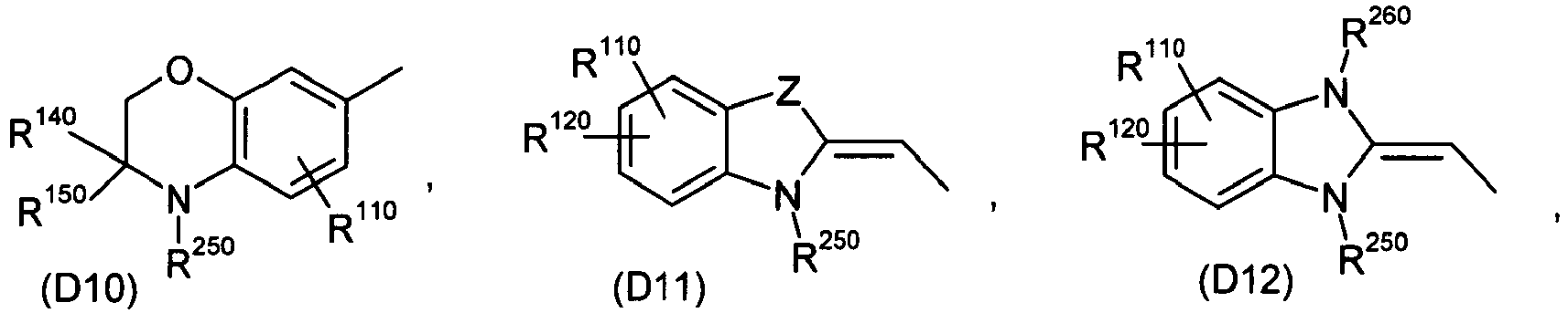
zur Herstellung von photoaktiven Schichten für organische Solarzellen und organische Photodetektoren gefunden. - Insbesondere ist die Donorgruppierung D in den ein oder mehreren Verbindungen der allgemeinen Formel k1 ausgewählt aus der Gruppe bestehend aus:


- R110, R120 und R130
- unabhängig voneinander Wasserstoff, Halogen, Hydroxy, C1-C10-Alkyl, das durch ein oder zwei nicht benachbarte Sauerstoffatome unterbrochen sein kann, C5-C7-Cycloalkyl, C1-C10-Alkoxy, C1-C10-Alkylamino, Di(C1-C10-alkyl)amino, C1-C10-Alkylamino- oder Di(C1-C10-alkyl)aminosulfonyl-amino, C1-C10-Alkylsulfonylamino, Aryl, Aryl-C1-C10-alkyl, Aryloxy-C1-C10-alkyl oder einen Rest-NHCOR170 oder-NHCOOR170, worin R170 die Bedeutung von Aryl, Aryl-C1-C10-alkyl oder C1-C10-Alkyl, das durch ein oder zwei nicht benachbarte Sauerstoffatome unterbrochen sein kann, besitzt,
- R140, R150 und R160
- unabhängig voneinander Wasserstoff, C1-C10-Alkyl, das durch ein oder zwei nicht benachbarte Sauerstoffatome unterbrochen sein kann, C5-C7-Cycloalkyl oder Aryl,
- R210, R220, R230 und R240
- unabhängig voneinander C1-C10-Alkyl, das durch ein oder zwei nicht benachbarte Sauerstoffatome unterbrochen sein kann, oder C5-C7-Cycloalkyl, oder R210 und R220 und/oder R230 und R240 bilden zusammen mit dem Stickstoffatom, an welches sie gebunden sind, einen fünf- oder sechsgliedrigen Ring, in welchem eine der zum Stickstoffatom nicht benachbarten CH2-Gruppen durch ein Sauerstoffatom ersetzt sein kann,
- R250 und R260
- unabhängig voneinander C1-C10-Alkyl, das durch ein oder zwei nicht benachbarte Sauerstoffatome unterbrochen sein kann, C5-C7-Cycloalkyl, Aryl, Aryl-C1-C10-alkyl oder Aryloxy-C1-C10-alkyl
und - Z
- O oder S.
- Die Definitionen der vorstehend aufgeführten Variablen werden nachfolgend erläutert und sind wie nachfolgend zu verstehen.
- Halogen bezeichnet Fluor, Chlor, Brom und lod, insbesondere Fluor und Chlor.
- Unter C1-C10-Alkyl ist lineares oder verzweigtes Alkyl, beispielsweise Methyl, Ethyl, n-Propyl, Isopropyl, n-Butyl, Isobutyl, sec.-Butyl, tert.-Butyl, n-Pentyl, n-Hexyl, n-Heptyl, n-Octyl, 2-Ethylhexyl, n-Nonyl und n-Decyl zu verstehen. Bevorzugte Gruppen sind Methyl, Isopropyl, n-Butyl, tert.-Butyl und 2-Ethylhexyl; in den genannten Resten können gegebenenfalls ein oder mehrere Wasserstoffatome durch Fluoratome ersetzt sein, so dass diese Reste auch teilfluoriert oder perfluoriert sein können.
- Unter C1-C10-Alkyl, welches durch ein oder zwei nicht benachbarte Sauerstoffatome unterbrochen ist, ist beispielsweise 3-Methoxyethyl, 2- und 3-Methoxy-propyl, 2-Ethoxyethyl, 2- und 3-Ethoxypropyl, 2-Propoxyethyl, 2- und 3-Propoxypropyl, 2-Butoxyethyl, 2- und 3-Butoxypropyl, 3,6-Dioxaheptoyl und 3,6-Dioxaoctyl zu nennen.
- Die C1-C10-Alkoxy-, C1-C10-Alkylamino-, Di(C1-C10-alkyl)amino-, C1-C10-Alkylamino-sulfonylamino-, Di(C1-C10-alkyl)aminosulfonylamino- und C1-C10-Alkylsulfonylamino-Reste leiten sich entsprechend von den zuvor genannten C1-C10-Alkylresten ab, wobei sich im Falle der Di(C1-C10-alkyl)amino-Gruppen sowohl gleiche als auch unterschiedliche C1-C10-Alkyl-Reste an der Amino-Gruppe befinden können. Beispielsweise sind zu nennen Methoxy, Ethoxy, n-Propoxy, Isopropoxy, n-Butoxy, Isobutoxy, sec.-Butoxy, tert.-Butoxy, n-Pentoxy, n-Hexoxy, n-Heptoxy, n-Octoxy, 2-Ethylhexoxy, n-Nonoxy und n-Decoxy, Methylamino, Ethylamino, n-Propylamino, Isopropylamino, n-Butylamino, Isobutylamino, sec.-Butylamino, tert.-Butylamino, n-Pentylamino, n-Hexylamino, n-Heptylamino, n-Octylamino, 2-Ethylhexylamino, n-Nonylamino und n-Decylamino, Dimethylamino, Diethylamino, Di(n-propyl)amino, Diisopropylamino, Di(n-butyl)amino, Diisobutylamino, Di(sec.-butyl)amino, Di(tert.-butyl)amino, Di(n-pentyl)amino, Di(n-hexyl)amino, Di(n-heptyl)amino, Di(n-octyl)amino, Di(2-ethylhexyl)amino, Di(n-nonyl)-amino und Di(n-decyl)amino sowie die entsprechenden gemischten Dialkylamino-Reste, wie etwa Methylethylamino bis Methyl-n-decylamino, Ethyl-n-propylamino bis Ethyl-n-decylamino usw., desweiteren Methylaminosulfonylamino, Ethylaminosulfonylamino, n-Propyl-aminosulfonylamino, Isopropylaminosulfonylamino, n-Butylaminosulfonylamino, Isobutylaminosulfonylamino, sec.-Butylaminosulfonylamino, tert.-Butylaminosulfonylamino, n-Pentylaminosulfonylamino, n-Hexylaminosulfonylamino, n-Heptylaminosulfonylamino, n-Octylaminosulfonylamino, 2-Ethylhexylaminosulfonylamino, n-Nonylaminosulfonylamino und n-Decylaminosulfonylamino, Dimethylaminosulfonylamino, Diethylaminosulfonylamino, Di(n-propyl)aminosulfonylamino, Diisopropylaminosulfonylamino, Di(n-butyl)aminosulfonylamino, Diisobutylaminosulfonylamino, Di(sec.-butyl)amino-sulfonylamino, Di(tert.-butyl)aminosulfonylamino, Di(n-pentyl)-aminosulfonylamino, Di(n-hexyl)aminosulfonylamino, Di(n-heptyl)aminosulfonylamino, Di(n-octyl)aminosulfonylamino, Di(2-ethylhexyl)aminosulfonylamino, Di(n-nonyl)aminosulfonylamino und Di(n-decyl)aminosulfonylamino sowie die entsprechenden, gemischte Dialkylamino-Reste enthaltenden Reste, wie etwa Methylethylaminosulfonylamino bis Methyl-n-decyl-aminosulfonylamino, Ethyl-n-propylaminosulfonylamino bis Ethyl-n-decylaminosulfonylamino usw. bis zu n-Nonyl-n-decylaminosulfonylamino sowie Methylsulfonylamino, Ethylsulfonylamino, n-Propylsulfonylamino, Isopropylsulfonylamino, n-Butylsulfonylamino, Isobutylsulfonylamino, sec.-Butylsulfonylamino, tert.-Butylsulfonylamino, n-Pentylsulfonylamino, n-Hexylsulfonylamino, n-Heptylsulfonylamino, n-Octylsulfonylamino, 2-Ethylhexylsulfonylamino, n-Nonylsulfonylamino und n-Decylsulfonylamino.
- Unter C5-C7-Cylcloalkyl sind insbesondere Cylcopentyl, Cyclohexyl und Cycloheptyl zu verstehen.
- Aryl umfasst ein- oder mehrkernige aromatische Kohlenwasserstoffreste, die unsubstituiert oder substituiert sein können. Aryl steht vorzugsweise für Phenyl, Tolyl, Xylyl, Mesityl, Duryl, Naphthyl, Fluorenyl, Anthracenyl, Phenanthrenyl oder Naphthyl, besonders bevorzugt für Phenyl oder Naphthyl, wobei diese Arylgruppen im Falle einer Substitution im Allgemeinen 1, 2, 3, 4 oder 5, vorzugsweise 1, 2 oder 3 Substituenten tragen können, die ausgewählt sind aus der Gruppe der Reste bestehend aus C1-C10-Alkyl, C1-C10-Alkoxy, Cyano, Nitro, SO2NRaRb, NHSO2NRaRb, CONRaRb und CO2Ra, wobei sich die C1-C10-Alkoxygruppen von den zuvor aufgeführten C1-C10-Alkylgruppen ableiten. Ra und Rb stehen vorzugsweise unabhängig voneinander für Wasserstoff oder C1-C10-Alkyl.
- Die Aryl-C1-C10-alkyl- und Aryloxy-C1-C10-Alkylgruppen leiten sich von den zuvor aufgeführten Alkyl- und Arylgruppen durch formalen Ersatz eines Wasserstoffatoms der linearen oder verzweigten Alkylkette durch eine Aryl- oder Aryloxygruppe ab. Bevorzugte Gruppen sind hier Benzyl und lineares Aryloxy-C1-C10-alkyl, wobei im Falle von C2-C10-Alkylresten der Aryloxyrest vorzugsweise terminal gebunden ist.
- In den photoaktiven Schichten kann die Komponente K1 die Rolle des Elektronendonors übernehmen, entsprechend kommt dann der Komponente K2 die Rolle des Elektronenakzeptors zu. Alternativ kann aber auch die die Komponente K1 die Rolle des Elektronenakzeptors annehmen, entsprechend fungiert dann Komponente K2 als Elektronendonor. In welcher Weise die jeweilige Komponente wirkt hängt von der Energie des HOMO bzw. LUMO der Komponente K1 im Verhältnis zur Energie des HOMO bzw. LUMO der Komponente K2 ab. Bei den Verbindungen der Komponente K1, insbesondere bei den Verbindungen mit den zuvor aufgeführten, bevorzugten Donorgruppierungen D01 bis D14 und Akzeptorgruppierungen A01 bis A09, handelt es sich typischerweise um Merocyanine, welche üblicherweise als Elektronendonoren in Erscheinung treten. Insbesondere ist dies der Fall, wenn als Komponente K2 Rylen- oder Fulleren-Derivate Verwendung finden, welche dann in der Regel als Elektronenakzeptoren wirken. Diese Rollen können sich im konkreten Einzelfall jedoch vertauschen. Anzumerken ist auch, dass Komponente K2 ebenfalls der strukturellen Definition der Komponente K1 gehorchen kann, so dass eine Verbindung der Formel D-A die Rolle des Elektronendonors und eine andere Verbindung der Formel D-A die Rolle des Elektronenakzeptors übernehmen kann.
- Vorzugsweise finden Mischungen erfindungsgemäße Verwendung, in welchen die Verbindungen der allgemeinen Formel k1 oder die bevorzugten Verbindungen, in welchen den Donorgruppierungen D und/oder den Akzeptorverbindungen A die zuvor aufgeführte Bedeutung der Gruppierungen D01 bis D14 bzw. A01 bis 09 zukommt, jeweils eine Molekülmasse von maximal 1.000 g/mol, insbesondere maximal 600 g/mol besitzen.
- Weiter finden insbesondere Verwendung solche Mischungen, unter Berücksichtigung der zuvor aufgeführten Bevorzugungen, in welchen es sich bei Komponente K2 um ein oder mehrere Fullerene und/oder Fulleren-Derivate handelt.
- Als mögliche Fullerene sind zu nennen C60, C70, C76, C80, C82, C84, C86, C90 und C94, insbesondere das C60 und C70. Einen Überblick über Fullerene, welche erfindungsgemäß verwendet werden können, liefert beispielsweise die Monografie von A. Hirsch, M. Brettreich, "Fullerenes: Chemistry and Reactions", Wiley-VCH, Weinheim 2005.
- Die Fulleren-Derivate erhält man üblicherweise durch Reaktion an einer oder mehreren der in den Fullerenen enthaltenen Kohlenstoff-Kohlenstoff-Doppelbindungen, wobei der Charakter der Fulleren-Einheit in den resultierenden Derivaten im Wesentlichen nicht verändert wird.
- Unter Berücksichtigung der zuvor aufgeführten Bevorzugungen finden insbesondere solche Mischungen erfindungsgemäße Verwendung, in welchen es sich bei Komponente K2 um ein oder mehrere C60-Fulleren-Derivate der allgemeinen Formel k2

worin bedeuten - A
- C1-C10-Alkylen,
- R510
- Aryl oder Aryl-C1-C10-alkyl und
- R520
- C1-C10-Alkyl.
- Zur Definition von Aryl, Aryl-C1-C10-alkyl und C1-C10-Alkyl wird auf das bereits zuvor Gesagte verwiesen.
- Unter C1-C10-Alkylen ist insbesondere eine lineare Kette -(CH2)n-, mit n gleich 1, 2, 3, 4, 5, 6, 7, 8, 9 oder 10, zu verstehen.
- Insbesondere finden erfindungsgemäß solche Fulleren-Derivate Verwendung, in welchen R520 einen C1-C4-Alkyl-, insbesondere einen Methylrest, bezeichnet, A für eine Propylen-Kette -(CH2)3- und R510 für ein gegebenenfalls substituiertes Phenyl oder 2-Thienyl steht. Vorzugsweise handelt es sich bei dem Fulleren-Derivat um [6,6]-Phenyl-C61-butylsäuremethylester ("PCBM").
- Besonders bevorzugt zu verwendende Verbindungen der Formel k1 ergeben sich durch Kombination der bevorzugten Donorgruppierungen D01 bis D14 mit den bevorzugten Akzeptorgruppierungen A01 bis A09. Die daraus resultierenden Verbindungen ergeben sich in vereinfachender Schreibweise zu
- D01-A01, D01-A02, D01-A03, D01-A04, D01-A05, D01-A06, D01-A07, D01-A08, D01-A09,
- D02-A01, D02-A02, D02-A03, D02-A04, D02-A05, D02-A06, D02-A07, D02-A08, D02-A09,
- D03-A01, D03-A02, D03-A03, D03-A04, D03-A05, D03-A06, D03-A07, D03-A08, D03-A09,
- D04-A01, D04-A02, D04-A03, D04-A04, D04-A05, D04-A06, D04-A07, D04-A08, D04-A09,
- D05-A01, D05-A02, D05-A03, D05-A04, D05-A05, D05-A06, D05-A07, D05-A08, D05-A09,
- D06-A01, D06-A02, D06-A03, D06-A04, D06-A05, D06-A06, D06-A07, D06-A08, D06-A09,
- D07-A01, D07-A02, D07-A03, D07-A04, D07-A05, D07-A06, D07-A07, D07-A08, D07-A09,
- D08-A01, D08-A02, D08-A03, D08-A04, D08-A05, D08-A06, D08-A07, D08-A08, D08-A09,
- D09-A01, D09-A02, D09-A03, D09-A04, D09-A05, D09-A06, D09-A07, D09-A08, D09-A09,
- D10-A01, D10-A02, D10-A03, D10-A04, D10-A05, D10-A06, D10-A07, D10-A08, D10-A09,
- D11-A01, D11-A02, D11-A03, D11-A04, D11-A05, D11-A06, D11-A07, D11-A08, D11-A09,
- D12-A01, D12-A02, D12-A03, D12-A04, D12-A05, D12-A06, D12-A07, D12-A08, D12-A09,
- D13-A01, D13-A02, D13-A03, D13-A04, D13-A05, D13-A06, D13-A07, D13-A08, D13-A09,
- D14-A01, D14-A02, D14-A03, D14-A04, D14-A05, D14-A06, D14-A07, D14-A08 und D14-A09.
- Ganz besonders bevorzugt sind zu verwenden die Verbindungen der Kombination
- D01-A01, D01-A02, D01-A03, D01-A04, D01-A05, D01-A06, D01-A07, D01-A08, D01-A09,
- D02-A01, D02-A02, D02-A03, D02-A04, D02-A05, D02-A06, D02-A07, D02-A08, D02-A09,
- D03-A01, D03-A02, D03-A03, D03-A04, D03-A05, D03-A06, D03-A07, D03-A08, D03-A09,
- D04-A01, D04-A02, D04-A03, D04-A04, D04-A05, D04-A06, D04-A07, D04-A08, D04-A09,
- D05-A01, D05-A02, D05-A03, D05-A04, D05-A05, D05-A06, D05-A07, D05-A08, D05-A09,
- D06-A01, D06-A02, D06-A03, D06-A04, D06-A05, D06-A06, D06-A07, D06-A08 und D06-A09.
- Explizit sind nachfolgend gezeigt die Verbindungen D01-A01, D01-A02, D01-A03, D01-A04, D01-A05, D01-A06, D01-A07, D01-A08 und D01-A09
- Die Variablen besitzen hierbei die zuvor aufgeführten Bedeutungen.
- Herstellungsbedingt ist es im Einzelfall möglich, dass nicht eine explizit gezeigte, sondern eine dazu isomere Verbindung erhalten wird oder dass auch Mischungen von Isomeren erhalten werden. Erfindungsgemäß sollen dementsprechend auch die isomeren Verbindungen der Formel k1 bzw. die Isomeren der entsprechenden bevorzugten und besonders bevorzugten Verbindungen sowie Mischungen von Isomeren umfasst sein.
- Die Synthese der Verbindungen der allgemeinen Formel k1, insbesondere die Synthese der Verbindungen der zuvor gezeigten Formeln
- D01-A01, D01-A02, D01-A03, D01-A04, D01-A05, D01-A06, D01-A07, D01-A08, D01-A09,
- D02-A01, D02-A02, D02-A03, D02-A04, D02-A05, D02-A06, D02-A07, D02-A08, D02-A09,
- D03-A01, D03-A02, D03-A03, D03-A04, D03-A05, D03-A06, D03-A07, D03-A08, D03-A09,
- D04-A01, D04-A02, D04-A03, D04-A04, D04-A05, D04-A06, D04-A07, D04-A08, D04-A09,
- D05-A01, D05-A02, D05-A03, D05-A04, D05-A05, D05-A06, D05-A07, D05-A08, D05-A09,
- D06-A01, D06-A02, D06-A03, D06-A04, D06-A05, D06-A06, D06-A07, D06-A08 und D06-A09
- Insbesondere sind hinsichtlich entsprechender Synthesen die nachfolgenden Publikationen zu nennen:
-
DE 195 02 702 A1 ; -
EP 416 434 A2 -
EP 509 302 A1 - "ATOP Dyes. Optimization of a Multifunctional Merocyanine Chromophore for High Refractive Index Modulation in Photorefractive Materials", F. Würthner, S. Yao, J. Schilling, R. Wortmann, M. Redi- Abshiro, E. Mecher, F. Gallego-Gomez, K. Meerholz, J. Am. Chem. Soc. 2001, 123, 2810 - 2814;
- "Merocyaninfarbstoffe im Cyaninlimit: eine neue Chromophorklasse für photorefraktive Materialien; Merocyanine Dyes in the Cyanine Limit: A New Class of Chromophores for Photorefractive Materials", F. Würthner, R. Wortmann, R. Matschiner, K. Lukaszuk, K. Meerholz, Y. De Nardin, R. Bittner, C. Bräuchle, R. Sens, Angew. Chem. 1997, 109, 2933 - 2936; Angew. Chem. Int. Ed. Engl. 1997, 36, 2765 - 2768;
- "Electrooptical Chromophores for Nonlinear Optical and Photorefractive Applications", S. Beckmann, K.-H. Etzbach, P. Krämer, K. Lukaszuk, R. Matschiner, A. J. Schmidt, P. Schuhmacher, R. Sens, G. Seybold, R. Wortmann, F. Würthner, Adv. Mater. 1999, 11, 536 - 541;
- "DMF in Acetic Anhydride: A Useful Reagent for Multiple- Component Syntheses of Merocyanine Dyes", F. Würthner, Synthesis 1999, 2103 - 2113;
- Ullmanns' Encyclopedia of industrial Chemistry, Vol. 16, 5th Edition (Ed. B. Elvers, S. Hawkins, G. Schulz), VCH 1990 im Kapitel "Methine Dyes and Pigments", S. 487 - 535 von R. Raue (Bayer AG).
- Bevorzugte erfindungsgemäße Verwendung finden Mischungen, welche dadurch gekennzeichnet sind, dass die Komponente K1 in einem Anteil von 10 bis 90 Massen-% und die Komponente K2 in einem Anteil von 90 bis 10 Massen-% vorliegt, wobei sich die Anteile der Komponenten K1 und K2, jeweils bezogen auf die Gesamtmasse der Komponenten K1 und K2, zu 100 Massen-% ergänzen.
- Besonders bevorzugte Verwendung finden Mischungen, welche dadurch gekennzeichnet sind, dass die Komponente K1 in einem Anteil von 20 bis 80 Massen-% und die Komponente K2 in einem Anteil von 80 bis 20 Massen-% vorliegt, wobei sich die Anteile der Komponenten K1 und K2, jeweils bezogen auf die Gesamtmasse der Komponenten K1 und K2, wiederum zu 100 Massen-% ergänzen.
- Weiter werden im Rahmen der vorliegenden Erfindung organische Solarzellen und organische Photodetektoren beansprucht, welche photoaktive Schichten enthalten, die unter Verwendung der zuvor beschriebenen, die Komponenten K1 und K2 enthaltenden Mischungen, oder unter Verwendung der ebenfalls zuvor beschriebenen bevorzugten Ausführungsformen der Mischungen hergestellt worden sind.
- Organische Solarzellen sind meist schichtförmig aufgebaut und umfassen in der Regel zumindest die folgenden Schichten: Elektrode, photoaktive Schicht und Gegenelektrode. Diese Schichten befinden sich in der Regel auf einem dafür üblichen Substrat. Geeignete Substrate sind z.B. oxidische Materialien, wie etwa Glas, Quartz, Keramik, SiO2, etc., Polymere, wie etwa Polyvinylchlorid, Polyolefine, z.B. Polyethylen und Polypropylen, Polyester, Fluorpolymere, Polyamide, Polyurethane, Polyalkyl(meth)-acrylate, Polystyrol und Mischungen und Komposite davon, und Kombinationen der zuvor aufgeführten Substrate.
- Als Materialien für die eine Elektrode eignen sich insbesondere Metalle, wie z.B. die Alkalimetalle Li, Na, K, Rb und Cs, die Erdalkalimetalle Mg, Ca und Ba, Pt, Au, Ag, Cu, Al, In, Metalllegierungen, z.B. auf Basis Pt, Au, Ag, Cu, etc. und spezielle Mg/Ag-Legierungen, des weiteren aber auch Alkalimetallfluoride, wie LiF, NaF, KF, RbF und CsF, und Mischungen aus Alkalimetallfluoriden und Alkalimetallen. Bevorzugt wird als Elektrode ein das einfallende Licht im Wesentlichen reflektierendes Material eingesetzt. Dazu zählen beispielsweise Metallfilme aus Al, Ag, Au, In, Mg, Mg/Al, Ca, etc.
- Die Gegenelektrode besteht aus einem, gegenüber einfallendem Licht im Wesentlichen transparenten Material, z.B. ITO, dotiertes ITO, ZnO, TiO2, Cu, Ag, Au und Pt, wobei die letztgenannten Metalle in entsprechend dünnen Schichten vorliegen.
- Als "transparent" soll hierbei eine Elektrode/Gegenelektrode angesehen werden, wenn mindestens 50% der Strahlungsintensität in dem Wellenlängen-Bereich transmittiert wird, in welchem die photoaktive Schicht Strahlung absorbiert. Im Falle mehrerer photoaktiver Schichten soll eine Elektrode/Gegenelektrode als "transparent" angesehen werden, wenn mindestens 50% der Strahlungsintensität in den WellenlängenBereichen transmittiert wird, in welchen die photoaktiven Schichten Strahlung absorbieren.
- Zusätzlich zur photoaktiven Schicht können eine oder mehrere weitere Schichten in den erfindungsgemäßen organischen Solarzellen und Photodetektoren vorhanden sein, z.B. Elektronen tranportierende Schichten ("ETL", electron tranporting layers) und/oder Löcher transportierende Schichten ("HTL", hole transporting layers) und/oder blockierende Schichten, z.B. Excitonen blockierende Schichten ("EBL", excition blocking layers), die üblicherweise das einfallende Licht nicht absorbieren, oder auch Schichten, welche als Ladungstransportschichten dienen und gleichzeitig die Kontaktierung zu einer oder beiden Elektroden der Solarzelle verbessern. Die ETL und HTL können auch dotiert sein, so dass sich Zellen vom p-i-n-Typ ergeben, wie sie beispielsweise in der Publikation von J. Drechsel et al., Thin Solid Films 451 - 452 (2004), 515 - 517, beschrieben sind.
- Der Aufbau organischer Solarzellen ist des weiteren z.B. in den Schriften
WO 2004/083958 A2 ,US 2005/0098726 A1 undUS 2005/0224905 A1 beschrieben, worauf hier in vollem Umfang Bezug genommen wird. - Photodetektoren besitzen im Wesentlichen einen zu organischen Solarzellen analogen Aufbau, sie werden jedoch mit geeigneter Vorspannung betrieben, welche bei Einwirkung von Strahlungsenergie einen entsprechenden Stromfluss als Messantwort generiert.
- Die Prozessierung der photoaktiven Schichten erfolgt beispielsweise aus Lösung. Hierbei können die Komponenten K1 und K2 bereits gemeinsam gelöst, aber auch separat als Lösung der Komponente K1 und Lösung der Komponente K2 vorliegen, wobei die Vermischung der entsprechenden Lösungen in letzterem Fall kurz vor der Aufbringung auf die darunterliegende Schicht erfolgt. Die Konzentrationen der Komponenten K1 und K2 belaufen sich in der Regel auf etwa einige g/l bis einige zehn g/l Lösungsmittel.
- Als Lösungsmittel eignen sich alle Flüssigkeiten, welche rückstandsfrei verdampfen und eine ausreichende Löslichkeit für die Komponenten K1 und K2 aufweisen. Hier kommen beispielsweise in Frage aromatische Verbindungen, wie etwa Benzol, Toluol, Xylol, Mesitylen, Chlorbenzol oder Dichlorbenzol, Trialkylamine, stickstoffhaltige Heterocyclen, N,N-disubstituierte aliphatische Carbonsäureamide, wie etwa Dimethylformamid, Diethylformamid, Dimethylacetamid oder Dimethylbutyramid, N-Alkyllactame, wie etwa N-Methylpyrrolidon, lineare und cyclische Ketone, wie etwa Methylethylketon, Cyclopentanon oder Cyclohexanon, cyclische Ether, wie etwa Tetrahydrofuran, oder Alkohole, wie etwa Methanol, Ethanol, Propanol, Isopropanol oder Butanol.
- Desweiteren können auch Mischungen der vorgenannten Lösungsmittel Verwendung finden.
- Geeignete Methoden zur Aufbringung der erfindungsgemäßen photoaktiven Schichten aus flüssiger Phase sind dem Fachmann bekannt. Vorteilhaft zeigt sich hier insbesondere die Prozessierung mittels Spin-Coating, da die Dicke der photoaktiven Schicht in einfacher Weise durch die Menge und/oder Konzentration der verwendeten Lösung sowie die Rotationsgeschwindigkeit und/oder Rotationsdauer gesteuert werden kann. Die Prozessierung der Lösung erfolgt in der Regel bei Raumtemperatur.
- Weiter ist bei geeigneter Auswahl der Komponenten K1 und K2 aber auch die Prozessierung aus der Gasphase möglich, insbesondere durch Vakuumsublimation.
- Im Rahmen der vorliegenden Erfindung werden auch Mischungen beansprucht, welche als Komponenten enthalten
- K1) ein oder mehrere Verbindungen der allgemeinen Formel k1
D-A (k1)
worin bedeuten - D eine Donorgruppierung, welche mindestens eine Kohlenstoff-Kohlenstoff- oder Kohlenstoff-Heteroatom-Doppelbindung und mindestens einen, gegebenenfalls anellierten carbo- oder heterocyclischen Ring enthält, ausgewählt ist aus der Gruppe bestehend aus:
- R110, R120 und R130
- unabhängig voneinander Wasserstoff, Halogen, Hydroxy, C1-C10-Alkyl, das durch ein oder zwei nicht benachbarte Sauerstoffatome unterbrochen sein kann, C5-C7-Cycloalkyl, C1-C10-Alkoxy, C1-C10-Alkylamino, Di(C1-C10-alkyl)amino, C1-C10-Alkylamino- oder Di(C1-C10-alkyl)aminosulfonylamino, C1-C10-Alkylsulfonylamino, Aryl, Aryl-C1-C10-alkyl, Aryloxy-C1-C10-alkyl oder einen Rest -NHCOR170 oder -NHCOOR170, worin R170 die Bedeutung von Aryl, Aryl-C1-C10-alkyl oder C1-C10-Alkyl, das durch ein oder zwei nicht benachbarte Sauerstoffatome unterbrochen sein kann, besitzt,
- R140, R150 und R160
- unabhängig voneinander Wasserstoff, C1-C10-Alkyl, das durch ein oder zwei nicht benachbarte Sauerstoffatome unterbrochen sein kann, C5-C7-Cycloalkyl oder Aryl,
- R210, R220, R230 und R240
- unabhängig voneinander C1-C10-Alkyl, das durch ein oder zwei nicht benachbarte Sauerstoffatome unterbrochen sein kann, oder C5-C7-Cycloalkyl, oder R210 und R220 und/oder R230 und R240 bilden zusammen mit dem Stickstoffatom, an welches sie gebunden sind, einen fünf- oder sechsgliedrigen Ring, in welchem eine der zum Stickstoffatom nicht benachbarten CH2-Gruppen durch ein Sauerstoffatom ersetzt sein kann,
- R250 und R260
- unabhängig voneinander C1-C10-Alkyl, das durch ein oder zwei nicht benachbarte Sauerstoffatome unterbrochen sein kann, C5-C7-Cycloalkyl, Aryl, Aryl-C1-C10-alkyl oder Aryloxy-C1-C10-alkyl
und - Z
- O oder S,
- A eine Akzeptorgruppierung, welche mindestens eine Kohlenstoff-Kohlenstoff- oder Kohlenstoff-Heteroatom-Doppelbindung und mindestens einen, gegebenenfalls anellierten carbo- oder heterocyclischen Ring enthält, ausgewählt ist aus der Gruppe bestehend aus:


- R310 und R320
- unabhängig voneinander Wasserstoff, C1-C10-Alkyl, das durch ein oder zwei nicht benachbarte Sauerstoffatome unterbrochen sein kann, oder C5-C7-Cycloalkyl,
- R330
- Wasserstoff, C1-C10-Alkyl, das durch ein oder zwei nicht benachbarte Sauerstoffatome unterbrochen sein kann, teilweise fluoriertes C1-C10-Alkyl, perfluoriertes C1-C10-Alkyl, C5-C7-Cyclo-alkyl oder Aryl,
- R340
- Wasserstoff, NO2, CN, COR350, COOR350, SO2R350 oder SO3R350, worin R350 die Bedeutung von Aryl oder C1-C10-Alkyl besitzt,
- R410
- C1-C10-Alkyl, das durch ein oder zwei nicht benachbarte Sauerstoffatome unterbrochen sein kann, C5-C7-Cycloalkyl, Aryl, Aryl-C1-C10-alkyl, Aryloxy-C1-C10-Alkyl, einen Rest -NHCOR420 oder einen Rest -N(CO R420)2, worin R420 die Bedeutung von Aryl, Aryl-C1-C10-alkyl oder C1-C10-Alkyl, das durch ein oder zwei nicht benachbarte Sauerstoffatome unterbrochen sein kann, besitzt, und die beiden R420 im Rest -N(CO R420)2 gleich oder voneinander verschieden sein können,
- X
- unabhängig voneinander CH oder N
und - Y
- O, C(CN)2 oder C(CN)(COOR430), worin R430 die Bedeutung C1-C10-Alkyl, das durch ein oder zwei nicht benachbarte Sauerstoffatome unterbrochen sein kann, besitzt,
und - K2) ein oder mehrere Fullerene und/oder Fulleren-Derivate.
- Bevorzugte erfindungsgemäße Mischungen enthalten als Komponenten
- K1) ein oder mehrere Verbindungen der allgemeinen Formel k1
D-A (k1)
und - K2) ein oder mehrere C60-Fulleren-Derivate der allgemeinen Formel k2

- A
- C1-C10-Alkylen,
- R510
- Aryl oder Aryl-C1-C10-alkyl
und - R520
- C1-C10-Alkyl
- Auf die Definition und Bevorzugungen der vorgenannten Variablen ist bereits weiter oben eingegangen worden.
- Die entsprechenden ganz besonders bevorzugten Verbindungen
- D01-A01, D01-A02, D01-A03, D01-A04, D01-A05, D01-A06, D01-A07, D01-A08, D01-A09,
- D02-A01, D02-A02, D02-A03, D02-A04, D02-A05, D02-A06, D02-A07, D02-A08, D02-A09,
- D03-A01, D03-A02, D03-A03, D03-A04, D03-A05, D03-A06, D03-A07, D03-A08, D03-A09,
- D04-A01, D04-A02, D04-A03, D04-A04, D04-A05, D04-A06, D04-A07, D04-A08, D04-A09,
- D05-A01, D05-A02, D05-A03, D05-A04, D05-A05, D05-A06, D05-A07, D05-A08, D05-A09,
- D06-A01, D06-A02, D06-A03, D06-A04, D06-A05, D06-A06, D06-A07, D06-A08 und D06-A09
- wurden bereits zuvor aufgeführt, auf sie wird auch im Bezug auf die erfindungsgemäßen Mischungen explizit Bezug genommen.
- Des Weiteren, und unter Berücksichtigung der zuvor erwähnten Bevorzugungen, werden solche erfindungsgemäßen Mischungen beansprucht, welche dadurch gekennzeichnet sind, dass die Komponente K1 in einem Anteil von 10 bis 90 Massen-% und die Komponente K2 in einem Anteil von 90 bis 10 Massen-% vorliegt, wobei sich die Anteile der Komponenten K1 und K2, jeweils bezogen auf die Gesamtmasse der Komponenten K1 und K2, zu 100 Massen-% ergänzen.
- Insbesondere, und unter Berücksichtigung der zuvor erwähnten Bevorzugungen, werden solche erfindungsgemäßen Mischungen beansprucht, welche dadurch gekennzeichnet sind, dass die Komponente K1 in einem Anteil von 20 bis 80 Massen-% und die Komponente K2 in einem Anteil von 80 bis 20 Massen-% vorliegt, wobei sich die Anteile der Komponenten K1 und K2, jeweils bezogen auf die Gesamtmasse der Komponenten K1 und K2, zu 100 Massen-% ergänzen.
- Die Erfindung wird anhand der folgenden, nicht einschränkenden Beispiele näher erläutert.
- Eingesetzte Verbindungen als Komponente K1 in den erfindungsgemäßen photoaktiven Schichten:
-

Kurzbezeichnung X R210 R220 R140 R310 R410 TAOP CH n-Butyl n-Butyl Phenyl Methyl n-Butyl -

Kurzbezeichnung X R210 R220 R140 R330 TAOX CH n-Butyl n-Butyl Phenyl Phenyl -

Kurzbezeichnung Z X R210 R220 R140 R150 R310 R410 AFOP O CH n-Butyl n-Butyl H H Methyl n-Butyl ATOP1 S CH n-Butyl n-Butyl H H Methyl n-Butyl ATOP4 S CH n-Butyl n-Butyl H H Methyl 2-Ethylhexyl ATOP7 S CH Ethyl n-Butyl H H Methyl n-Butyl ATOP8 S CH Ethyl n-Butyl H H Methyl n-Hexyl -

Kurzbezeichnung Z X R210 R220 R140 R150 R330 AFOX O CH n-Butyl n-Butyl H H Phenyl -

Kurzbezeichnung X R250 R110 R120 R140 R150 R310 R410 IDOP301 CH n-Butyl H H Methyl Methyl Methyl 2-Ethylhexyl IDOP305 CH Isopropyl H H Methyl Methyl Methyl 2-Ethylhexyl -

Kurzbezeichnung X R250 R110 R120 R140 R150 R330 Y IDTA303 CH Phenyl H H Methyl Methyl Phenyl C(CN)2 IDTA304 CH Benzyl H H Methyl Methyl tert.-Butyl C(CN)2 IDTA322 CH 7-Phenoxyheptyl H H Methyl Methyl Phenyl C(CN)2 - Eingesetzte Verbindung als Komponente K2 in den erfindungsgemäßen photoaktiven Schichten:

Kurzbe-zeichnung R510 R520 A PCBM Phenyl Methyl (CH2)3 - Allgemeiner Aufbau: üblicherweise erfolgt die Aufbringung der Schichten in der Reihenfolge (2) bzw. (3) bis (6). Im Falle kommerziell erhältlicher, mit ITO (Indiumzinnoxid) beschichteter Glasplatten ist die transparente Elektrode (2) bereits auf das Glassubstrat (1) aufgebracht.
(1) Transparentes Substrat: Glasplatte (2) Transparente Elektrode: 140 nm (3) Lochinjektionsschicht: 0 - 100 nm (4) Photoaktive Schicht: 30 - 500 nm (5) Metallelektrode: 0 - 200 nm (6) Verkapselung: für Versuchsaufbau optional (1) + (2): Transparentes Substrat und transparente Elektrode - Es wurden mit circa 140 nm ITO (Indiumzinnoxid) beschichtete Glasplatten der Firma Merck verwendet. Der Schichtwiderstand des ITOs betrug weniger als 15 Ω.
- Zur Verbesserung der Oberflächenbeschaffenheit und der Lochinjektion der ITO-Anode wurde die wässrige Suspension BAYTRON P VP I4083 der Firma H. C. Stark verwendet. In der Suspension ist neben PEDOT auch das Polymer Poly(styrolsulfonsäure) (PSSH) enthalten. Die PEDOT-Schichtdicke betrug ca. 35 nm. Nach dem Spin-Coaten wurden die PEDOT-Schichten zwei Minuten bei 110 °C ausgeheizt um Wasserreste zu entfernen.
- Als Komponente K1 wurden entweder Reinverbindungen der Formel k1 oder Mischungen von Verbindungen der Formel k1 verwendet (die Verbindungen der Formeln k1 werden im Folgenden auch als "Merocyanine" bezeichnet), welche nach an sich bekannten Synthesen hergestellt worden waren. Als Komponente K2 wurde das zuvor gezeigte Fulleren-Derivat [6,6]-PCBM (engl.: [6,6]-phenyl-C61 butyric acid methyl ester) der Firma Nano-C verwendet. Zur Herstellung der photoaktiven Bulk-Heterojunction-Schichten der untersuchten Solarzellen wurden Mischungen der Lösungen der einzelnen Komponenten K1 und K2 in Chlorbenzol mittels Spin-Coating aufgetragen. Die Lösungen der einzelnen Komponenten wurden kurz vor der Schichtherstellung in einer Konzentration von 20 g/L angesetzt und über Nacht bei 50 bis 70 °C gerührt. Direkt vor dem Lackschleudern wurden die Lösungen der einzelnen Komponenten vereinigt und gut gemischt. Die Schichtdicken wurden hauptsächlich durch die Rotationsgeschwindigkeit und weniger über die Rotationsdauer kontrolliert. Die Rotationsgeschwindigkeit wurde im Bereich 450 bis 2200 U/min variiert, die Rotationsdauern betrugen zwischen 20 und 40 Sekunden. Das Lösungsmittel verdampfte beim anschließenden Tempern und/oder während des für Schritt (5) notwendigen Evakuierens.
- Zum Aufdampfen der Metallelektrode (sogenannte "Top-Elektrode" da sie vor der Verkapselungsschicht die letzte aktive Schicht im Aufbau darstellt) wurden Aluminium, Barium und Silber in Granulatform mit einem Reinheitsgehalt von 99,9 % verwendet. Die Top-Elektrode wurde unter Hochvakuum von wenigstens 5 x 10⁻⁶ hPa aufgedampft, wobei die Verdampfungsrate anfangs klein gehalten (0,2 bis 0,5 nm/s) und erst mit zunehmender Schichtdicke auf 1,0 bis 1,5 nm/s erhöht wurde. Die aufgedampften Aluminiumschichten besaßen eine Dicke von etwa 150 nm.
- Folgende Abkürzungen werden verwendet:
- L:
- Dicke der photoaktiven Schicht
- VOC:
- Leerlaufspannung ("OC" steht für "open circuit")
- Vbi:
- Built-in-Spannung
- VOC,ideal:
- theoretische Leerlaufspannung
- JSC:
- Kurzschlussstromdichte ("SC" steht für "short circuit")
- FF:
- Füllfaktor
- η:
- Effizienz
- Abbildungen 1a bis 1d: Darstellung der Abhängigkeit der Kenngrößen von ATOP4: PCBM-Solarzellen mit einem ATOP4:PCBM-Massenverhältnis von 1:3 von der Schichtdicke L der photoaktiven Schicht.
- Abbildung 1a:
- Abhängigkeit der Leerlaufspannung VOC (in V) von der Schicktdicke L (in nm)
- Abbildung 1b:
- Abhängigkeit der Kurzschlussstromdichte JSC (in mA/cm2) von der Schichtdicke L (in nm)
- Abbildung 1c:
- Abhängigkeit des Füllfaktors FF von der Schichtdicke L (in nm)
- Abbildung 1d:
- Abhängigkeit der Effizienz (in %) von der Schichtdicke L (in nm)
- Abbildungen 2a bis 2d: Darstellung der Abhängigkeit der Kenngrößen von Solarzellen mit den ATOP-Derivaten ATOP1, ATOP4, ATOP7 und ATOP8 vom Massenanteil ATOP-Derivat: PCBM (der Massenanteil an PCBM und jeweiligem ATOP-Derivat ergänzt sich zu 100 %).
- Abbildung 2a:
- Abhängigkeit der Leerlaufspannung VOC (in V) vom Massenanteil PCBM (in %)
- Abbildung 2b:
- Abhängigkeit der Kurzschlussstromdichte JSC (in mA/cm2) vom Massenanteil PCBM (in %)
- Abbildung 2c:
- Abhängigkeit des Füllfaktors FF vom Massenanteil PCBM (in %)
- Abbildung 2d:
- Abhängigkeit der Effizienz (in %) vom Massenanteil PCBM (in %)
- Abbildungen 3a bis 3d: Darstellung der Abhängigkeit der relativen Kenngrößen von ATOP7:PCBM-Solarzellen mit einem Massenverhältnis für ATOP7:PCBM von 3:7 von der Temperdauer t (in min). Die relativen Kenngrößen wurden durch Verhältnisbildung der jeweiligen Kenngröße nach t min Temperung zum Startwert der Kenngröße ohne Temperung ermittelt. Die Temperungen wurden bei 95°C und 125°C durchgeführt.
- Die Startwerte ohne Temperung sind den Abbildungen 2a bis 2d zu entnehmen und betragen:
VOC,0= 0,63 V; JSC,0= 3,0 mA cm-2; FF0 = 0,32; η0 = 0,60 % - Die Werte der jeweiligen Kenngröße nach t min Temperung sind mit VOC,T, JSC,T, FFT und ηT bezeichnet.
- Abbildung 3a:
- Abhängigkeit des Verhältnisses VOC,T/VOC,0 von der Temperzeit t (in min)
- Abbildung 3b:
- Abhängigkeit des Verhältnisses JSC,T/JSC,0 von der Temperzeit t (in min)
- Abbildung 3c:
- Abhängigkeit des Verhältnisses FFT/FF0 von der Temperzeit t (in min)
- Abbildung 3d:
- Abhängigkeit des Verhältnisses ηT/η0 von der Temperzeit t (in min)
- Durch Tempern der Schichten (nach Abscheidung der Elektroden) können die Kenngrößen der Zellen etwas verbessert werden.
- Abbildungen 4a bis 4d: Darstellung der Abhängigkeit der Kenngrößen von Solarzellen vom Massenverhältnis ATOP1:AFOP, ATOP1:IDOP301 und ATOP1:IDTA304 in der photoaktiven Schicht. In allen Fällen wurden ein Massenverhältnis von (ATOP1:AFOP): PCBM, (ATOP1:IDOP301):PCBM und (ATOP1:IDTA304):PCBM von 1:3 eingestellt. Der Massenanteil der Verbindungen AFOP, IDOP301 und IDTA304 ist der oberen Abszisse (Beschriftung "Massenanteil Merocyanin [%]"), der Massenanteil der Verbindung ATOP1 der unteren Abszisse zu entnehmen. Beide Massenanteile ergänzen sich jeweils zu 25%, der Massenanteil an PCBM ergänzt sich jeweils zu 100% (entsprechend dem zuvor angeführten Verhältnis von 1:3).
- Abbildung 4a:
- Abhängigkeit der Leerlaufspannung VOC (in V) vom Verhältnis des Massenanteils ATOP1 (in %) zum Massenanteil der jeweiligen Verbindungen AFOP, IDOP301 und IDTA304 (in %)
- Abbildung 4b:
- Abhängigkeit der Kurzschlussstromdichte JSC (in mA/cm2) vom Verhältnis des Massenanteils ATOP1 (in %) zum Massenanteil der jeweiligen Verbindungen AFOP, IDOP301 und IDTA304 (in %)
- Abbildung 4c:
- Abhängigkeit des Füllfaktors FF vom Verhältnis des Massenanteils ATOP1 (in %) zum Massenanteil der jeweiligen Verbindungen AFOP, IDOP301 und IDTA304 (in %)
- Abbildung 4d:
- Abhängigkeit der Effizienz (in %) vom Verhältnis des Massenanteils ATOP1 (in %) zum Massenanteil der jeweiligen Verbindungen AFOP, IDOP301 und IDTA304 (in %)
- In nachfolgender Tabelle sind die Kenngrößen von Solarzellen mit verschiedenen Verbindungen der Formel D-A ("Merocyanin") aufgeführt. Dabei wurde in allen Fällen ein Massenverhältnis von Merocyanin:PCBM von 1:3 eingestellt.
Merocyanin L [nm] VOC [V] Vbi [V] VOC,ideal [V] JSC [mA/cm2] FF η [%] ATOP1 66 0,63 0,66 1,57 1,79 0,34 0,97 AFOP 61 0,59 0,62 1,52 1,21 0,29 0,51 AFOX 63 0,29 0,36 > 1,61 0,28 0,23 0,05 IDOP301 71 0,70 0,77 1,73 1,43 0,29 0,72 IDTA304 n.b. 1) 0,56 n.b. 1) 1,52 2,80 0,34 1,34 TAOP 71 0,49 0,58 1,82 0,45 0,27 0,15 TAOX 61 0,26 0,53 > 1,85 0,10 0,27 0,02 1) nicht bestimmt - In den zuvor untersuchten photoaktiven Schichten wirkte die Komponente K1 (d.h. die ein oder mehreren Merocyanine der Formel k1) als Elektronendonor und die Komponente K2 (d.h. das Fulleren-Derivat) als Elektronenakzeptor.
- Analog zu den vorherigen Versuchen wurden organische Solarzellen hergestellt, in welchen die photoaktive Schicht aus der Verbindung ATOP4 als Komponente K1 und der Verbindung Poly(3-hexyl-thiophen) ("P3HT") als Komponente K2 bestand, wobei letztere Verbindung üblicherweise Elektronendonor ist. Der Massenanteil von ATOP4 zu P3HT wurde im Bereich 1:3, 1:1 und 3:1 variiert. Die entsprechenden Effizienzen η ergaben sich zu 0,02%, 0,03% und 0%. Es wurde festgestellt, dass P3HT in dieser Kombination wiederum als Elektronendonor, ATOP4 dagegen als Elektronenakzeptor fungiert.






Claims (10)
- Verwendung von Mischungen, enthaltend als KomponentenK1) ein oder mehrere Verbindungen der allgemeinen Formel k1
D-A (k1)
als Elektronendonor bzw. Elektronenakzeptor, worin bedeutenD eine Donorgruppierung, welche mindestens eine Kohlenstoff-Kohlenstoff- oder Kohlenstoff-Heteroatom-Doppelbindung und mindestens einen, gegebenenfalls anellierten carbo- oder heterocyclischen Ring enthält,A eine Akzeptorgruppierung, ausgewählt aus der Gruppe bestehend aus:

 R310 und R320 unabhängig voneinander Wasserstoff, C1-C10-Alkyl, das durch ein oder zwei nicht benachbarte Sauerstoffatome unterbrochen sein kann, oder C5-C7-Cycloalkyl,R330 Wasserstoff, C1-C10-Alkyl, das durch ein oder zwei nicht benachbarte Sauerstoffatome unterbrochen sein kann, teilweise fluoriertes C1-C10-Alkyl, perfluoriertes C1-C10-Alkyl, C5-C7-Cycloalkyl oder Aryl,R340 Wasserstoff, NO2, CN, COR350, COOR350, SO2R353 oder SO3R350, worin R350 die Bedeutung von Aryl oder C1-C10-Alkyl besitzt,R410 C1-C10-Alkyl, das durch ein oder zwei nicht benachbarte Sauerstoffatome unterbrochen sein kann, C5-C7-Cycloalkyl, Aryl, Aryl-C1-C10-alkyl, Aryloxy-C1-C10-Alkyl, einen Rest -NHCOR420 oder einen Rest -N(CO R420)2, worin R420 die Bedeutung von Aryl, Aryl-C1-C10-alkyl oder C1-C10-Alkyl, das durch ein oder zwei nicht benachbarte Sauerstoffatome unterbrochen sein kann, besitzt, und die beiden R420 im Rest -N(CO R420)2 gleich oder voneinander verschieden sein können,X unabhängig voneinander CH oder N undY O, C(CN)2 oder C(CN)(COOR430), worin R430 die Bedeutung C1-C10-Alkyl, das durch ein oder zwei nicht benachbarte Sauerstoffatome unterbrochen sein kann, besitzt,und die Donorgruppierung D und die Akzeptorgruppierung A miteinander in π-Konjugation stehen,
undK2) ein oder mehrere Verbindungen, welche gegenüber Komponente K1) entsprechend als Elektronenakzeptor bzw. Elektronendonor wirken,zur Herstellung von photoaktiven Schichten für organische Solarzellen und organische Photodetektoren. - Verwendung nach Anspruch 1, dadurch gekennzeichnet, dass die Donorgruppierung D in den ein oder mehreren Verbindungen der allgemeinen Formel k1 ausgewählt ist aus der Gruppe bestehend aus:


 R110, R120 und R130 unabhängig voneinander Wasserstoff, Halogen, Hydroxy, C1-C10-Alkyl, das durch ein oder zwei nicht benachbarte Sauerstoffatome unterbrochen sein kann, C5-C7-Cycloalkyl, C1-C10-Alkoxy, C1-C10-Alkylamino, Di(C1-C10-alkyl)amino, C1-C10-Alkylamino- oder Di(C1-C10-alkyl)aminosulfonylamino, C1-C10-Alkylsulfonylamino, Aryl, Aryl-C1-C10-alkyl, Aryloxy-C1-C10-alkyl oder einen Rest - NHCOR170 oder -NHCOOR170, worin R170 die Bedeutung von Aryl, Aryl-C1-C10-alkyl oder C1-C10-Alkyl, das durch ein oder zwei nicht benachbarte Sauerstoffatome unterbrochen sein kann, besitzt,R140, R150 und R160 unabhängig voneinander Wasserstoff, C1-C10-Alkyl, das durch ein oder zwei nicht benachbarte Sauerstoffatome unterbrochen sein kann, C5-C7-Cycloalkyl oder Aryl,R210, R220, R230 und R240 unabhängig voneinander C1-C10-Alkyl, das durch ein oder zwei nicht benachbarte Sauerstoffatome unterbrochen sein kann, oder C5-C10-Cycloalkyl, oder R210 und R220 und/oder R230 und R240 bilden zusammen mit dem Stickstoffatom, an welches sie gebunden sind, einen fünf- oder sechsgliedrigen Ring, in welchem eine der zum Stickstoffatom nicht benachbarten CH2-Gruppen durch ein Sauerstoffatom ersetzt sein kann,R250 und R260 unabhängig voneinander C1-C10-Alkyl, das durch ein oder zwei nicht benachbarte Sauerstoffatome unterbrochen sein kann, C5-C7-Cycloalkyl, Aryl, Aryl-C1-C10-alkyl oder Aryloxy-C1-C10-alkyl
undZ O oder S. - Verwendung nach Anspruch 1 oder 2, dadurch gekennzeichnet, dass in Komponente K1) die ein oder mehreren Verbindungen der allgemeinen Formel k1 jeweils eine Molekülmasse von maximal 1.000 g/mol, insbesondere maximal 600 g/mol besitzen.
- Verwendung nach einem oder mehreren der Ansprüche 1 bis 3, dadurch gekennzeichnet, dass es sich bei Komponente K2 um ein oder mehrere Fullerene und/oder Fulleren-Derivate handelt.
- Verwendung nach einem oder mehreren der Ansprüche 1 bis 4, dadurch gekennzeichnet, dass es sich bei Komponente K2 um ein oder mehrere C60-Fulleren-Derivate der allgemeinen Formel k2
 A C1-C10-Alkylen,R510 Aryl oder Aryl-C1-C10-alkyl
undR520 C1-C10-Alkyl. - Verwendung nach einem oder mehreren der Ansprüche 1 bis 4, dadurch gekennzeichnet, dass die Komponente K1 in einem Anteil von 10 bis 90 Massen-%, insbesondere 20 bis 80 Massen-%, und die Komponente K2 in einem Anteil von 90 bis 10 Massen-%, insbesondere 80 bis 20 Massen-%, vorliegt, wobei sich die Anteile der Komponenten K1 und K2, jeweils bezogen auf die Gesamtmasse der Komponenten K1 und K2, zu 100 Massen-% ergänzen.
- Mischungen, enthaltend als KomponentenK1) ein oder mehrere Verbindungen der allgemeinen Formel k1
D-A (k1)
worin bedeutenD eine Donorgruppierung, ausgewählt aus der Gruppe bestehend aus:


 R110, R120 und R130 unabhängig voneinander Wasserstoff, Halogen, Hydroxy, C1-C10-Alkyl, das durch ein oder zwei nicht benachbarte Sauerstoffatome unterbrochen sein kann, C5-C7-Cycloalkyl, C1-C10-Alkoxy, C1-C10-Alkylamino, Di(C1-C10-alkyl)amino, C1-C10-Alkylamino- oder Di(C1-C10-alkyl)aminosulfonylamino, C1-C10-Alkylsulfonylamino, Aryl, Aryl-C1-C10-alkyl, Aryloxy-C1-C10-alkyl oder einen Rest-NHCOR170 oder -NHCOOR170, worin R170 die Bedeutung von Aryl, Aryl-C1-C10-alkyl oder C1-C10-Alkyl, das durch ein oder zwei nicht benachbarte Sauerstoffatome unterbrochen sein kann, besitzt,R140, R150 und R160 unabhängig voneinander Wasserstoff, C1-C10-Alkyl, das durch ein oder zwei nicht benachbarte Sauerstoffatome unterbrochen sein kann, C5-C7-Cycloalkyl oder Aryl,R210, R220, R230 und R240 unabhängig voneinander C1-C10-Alkyl, das durch ein oder zwei nicht benachbarte Sauerstoffatome unterbrochen sein kann, oder C5-C7-Cycloalkyl, oder R210 und R220 und/oder R230 und R240 bilden zusammen mit dem Stickstoffatom, an welches sie gebunden sind, einen fünf- oder sechsgliedrigen Ring, in welchem eine der zum Stickstoffatom nicht benachbarten CH2-Gruppen durch ein Sauerstoffatom ersetzt sein kann,R250 und R260 unabhängig voneinander C1-C10-Alkyl, das durch ein oder zwei nicht benachbarte Sauerstoffatome unterbrochen sein kann, C5-C7-Cycloalkyl, Aryl, Aryl-C1-C10-alkyl oder Aryloxy-C1-C10-alkyl
undZ O oder S,A eine Akzeptorgruppierung, ausgewählt aus der Gruppe bestehend aus: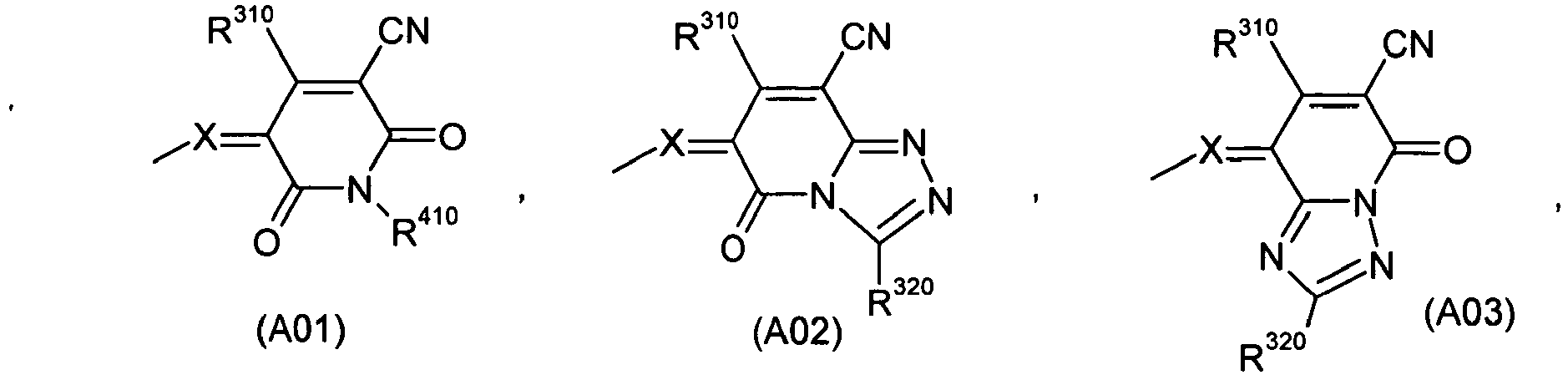

 R310 und R320 unabhängig voneinander Wasserstoff, C1-C10-Alkyl, das durch ein oder zwei nicht benachbarte Sauerstoffatome unterbrochen sein kann, oder C5-C7-Cycloalkyl,R330 Wasserstoff, C1-C10-Alkyl, das durch ein oder zwei nicht benachbarte Sauerstoffatome unterbrochen sein kann, teilweise fluoriertes C1-C10-Alkyl, perfluoriertes C1-C10-Alkyl, C1-C7-Cycloalkyl oder Aryl,R340 Wasserstoff, NO2, CN, COR350, COOR350, SO2R350 oder SO3R350, worin R350 die Bedeutung von Aryl oder C1-C10-Alkyl besitzt,R410 C1-C10-Alkyl, das durch ein oder zwei nicht benachbarte Sauerstoffatome unterbrochen sein kann, C5-C7-Cycloalkyl, Aryl, Aryl-C1-C10-alkyl, Aryloxy-C1-C10-Alkyl, einen Rest -NHCOR420 oder einen Rest -N(CO R420)2, worin R420 die Bedeutung von Aryl, Aryl-C1-C10-alkyl oder C1-C10-Alkyl, das durch ein oder zwei nicht benachbarte Sauerstoffatome unterbrochen sein kann, besitzt, und die beiden R420 im Rest -N(CO R420)2 gleich oder voneinander verschieden sein können,X unabhängig voneinander CH oder N
undY O, C(CN)2 oder C(CN)(COOR430), worin R430 die Bedeutung C1-C10-Alkyl, das durch ein oder zwei nicht benachbarte Sauerstoffatome unterbrochen sein kann, besitzt,und die Donorgruppierung D und die Akzeptorgruppierung A miteinander in π-Konjugation stehen,
undK2) ein oder mehrere Fullerene und/oder Fulleren-Derivate. - Mischung nach Anspruch 7, dadurch gekennzeichnet, dass es sich bei Komponente K2 um ein oder mehrere C60-Fulleren-Derivate der allgemeinen Formel k2
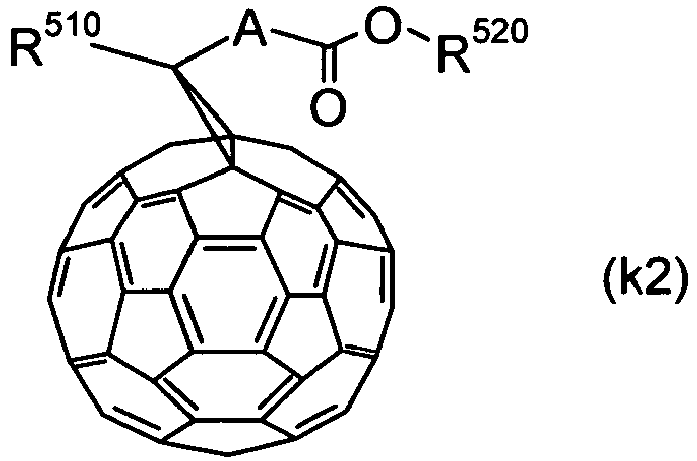 A C1-C10-Alkylen,R510 Aryl oder Aryl-C1-C10-alkyl
undR520 C1-C10-Alkyl. - Mischung nach Anspruch 7 oder 8, dadurch gekennzeichnet, dass die Komponente K1 in einem Anteil von 10 bis 90 Massen-%, insbesondere 20 bis 80 Massen-%, und die Komponente K2 in einem Anteil von 90 bis 10 Massen-%, insbesondere 80 bis 20 Massen-%, vorliegt, wobei sich die Anteile der Komponenten K1 und K2, jeweils bezogen auf die Gesamtmasse der Komponenten K1 und K2, zu 100 Massen-% ergänzen
- Organische Solarzellen und organische Photodetektoren, enthaltend photoaktive Schichten, welche Mischungen gemäß Ansprüchen 7-9 enthalten.
Priority Applications (1)
| Application Number | Priority Date | Filing Date | Title |
|---|---|---|---|
| EP08785954.2A EP2168181B1 (de) | 2007-07-10 | 2008-07-07 | Mischungen zur herstellung von photoaktiven schichten für organische solarzellen und organische photodetektoren |
Applications Claiming Priority (3)
| Application Number | Priority Date | Filing Date | Title |
|---|---|---|---|
| EP07112153 | 2007-07-10 | ||
| PCT/EP2008/058773 WO2009007340A1 (de) | 2007-07-10 | 2008-07-07 | Mischungen zur herstellung von photoaktiven schichten für organische solarzellen und organische photodetektoren |
| EP08785954.2A EP2168181B1 (de) | 2007-07-10 | 2008-07-07 | Mischungen zur herstellung von photoaktiven schichten für organische solarzellen und organische photodetektoren |
Publications (2)
| Publication Number | Publication Date |
|---|---|
| EP2168181A1 EP2168181A1 (de) | 2010-03-31 |
| EP2168181B1 true EP2168181B1 (de) | 2021-05-12 |
Family
ID=39832258
Family Applications (1)
| Application Number | Title | Priority Date | Filing Date |
|---|---|---|---|
| EP08785954.2A Active EP2168181B1 (de) | 2007-07-10 | 2008-07-07 | Mischungen zur herstellung von photoaktiven schichten für organische solarzellen und organische photodetektoren |
Country Status (8)
| Country | Link |
|---|---|
| US (1) | US20100140559A1 (de) |
| EP (1) | EP2168181B1 (de) |
| JP (1) | JP5436418B2 (de) |
| KR (1) | KR101464798B1 (de) |
| CN (1) | CN101689606B (de) |
| AU (1) | AU2008274270B2 (de) |
| WO (1) | WO2009007340A1 (de) |
| ZA (1) | ZA201000901B (de) |
Families Citing this family (21)
| Publication number | Priority date | Publication date | Assignee | Title |
|---|---|---|---|---|
| CN102203972A (zh) * | 2008-10-31 | 2011-09-28 | 巴斯夫欧洲公司 | 用于制备有机太阳能电池和有机光电探测器用光活化层的部花青 |
| WO2010137449A1 (ja) * | 2009-05-25 | 2010-12-02 | コニカミノルタホールディングス株式会社 | 有機光電変換素子、それを用いた太陽電池及び光センサアレイ |
| JP5520560B2 (ja) | 2009-09-29 | 2014-06-11 | 富士フイルム株式会社 | 光電変換素子、光電変換素子材料、光センサ、及び撮像素子 |
| CN102549792B (zh) * | 2009-10-13 | 2015-11-25 | 巴斯夫欧洲公司 | 生产有机太阳能电池和有机光检测器用光活性层的混合物 |
| JP5445086B2 (ja) * | 2009-12-07 | 2014-03-19 | コニカミノルタ株式会社 | 有機光電変換素子、それを用いた太陽電池及び光センサアレイ |
| JP5476969B2 (ja) * | 2009-12-14 | 2014-04-23 | コニカミノルタ株式会社 | 有機光電変換素子、太陽電池、及び光センサアレイ |
| US9012773B2 (en) | 2011-02-14 | 2015-04-21 | Nec Corporation | Thiazole-based compound and uses thereof |
| JP6063359B2 (ja) * | 2012-09-28 | 2017-01-18 | 富士フイルム株式会社 | 光電変換素子、色素増感太陽電池、金属錯体色素および金属錯体色素を溶解してなる色素溶液 |
| WO2014054759A1 (ja) * | 2012-10-03 | 2014-04-10 | 日本ケミコン株式会社 | 有機薄膜太陽電池 |
| JP5499193B2 (ja) * | 2013-02-04 | 2014-05-21 | 出光興産株式会社 | 有機薄膜太陽電池 |
| KR20150012163A (ko) | 2013-07-24 | 2015-02-03 | 제일모직주식회사 | 감광성 수지 조성물 및 이로부터 제조된 컬러필터 |
| KR101705757B1 (ko) * | 2014-02-17 | 2017-02-10 | 제일모직 주식회사 | 신규한 염료 화합물, 상기 염료 화합물을 포함하는 감광성 수지 조성물, 및 컬러 필터 |
| EP2937399A1 (de) | 2014-04-22 | 2015-10-28 | Basf Se | Lochstransportmaterialien für organische Solarzellen oder organische optische Sensoren |
| KR102314133B1 (ko) * | 2014-11-25 | 2021-10-15 | 삼성전자주식회사 | 유기 광전 소자용 화합물, 유기 광전 소자 및 이미지 센서 |
| CN107343746A (zh) * | 2017-04-05 | 2017-11-14 | 浙江苏泊尔家电制造有限公司 | 用于烹饪器具的内锅、烹饪器具和制造内锅的方法 |
| KR102285566B1 (ko) * | 2017-06-20 | 2021-08-03 | 주식회사 엘지화학 | 화합물 및 이를 포함하는 유기 전자 소자 |
| EP3489228A1 (de) * | 2017-11-24 | 2019-05-29 | LANXESS Deutschland GmbH | Neue methinfarbstoffe |
| GB201819628D0 (en) * | 2018-11-30 | 2019-01-16 | Sumitomo Chemical Co | Photodetector composition |
| CN113316572A (zh) * | 2019-04-26 | 2021-08-27 | 株式会社艾迪科 | 多次甲基化合物 |
| KR20230138752A (ko) | 2022-03-24 | 2023-10-05 | 삼성전자주식회사 | 화합물, 센서, 센서 내장형 표시 패널 및 전자 장치 |
| EP4561308A1 (de) | 2023-11-21 | 2025-05-28 | Dirk Dammers | Dünnschicht-solarzelle, insbesondere perowskit-solarzelle, solarmodul mit solchen dünnschicht-solarzellen und verfahren zu deren herstellung |
Family Cites Families (26)
| Publication number | Priority date | Publication date | Assignee | Title |
|---|---|---|---|---|
| US4743531A (en) * | 1986-11-21 | 1988-05-10 | Eastman Kodak Company | Dye sensitized photographic imaging system |
| DE3929698A1 (de) * | 1989-09-07 | 1991-03-14 | Basf Ag | Triazolopyridinfarbstoffe sowie ein verfahren zum thermischen transfer von methinfarbstoffen |
| JPH06318725A (ja) * | 1993-05-10 | 1994-11-15 | Ricoh Co Ltd | 光起電力素子およびその製造方法 |
| DE19502702A1 (de) * | 1995-01-28 | 1996-08-01 | Basf Ag | Thiazolmethinfarbstoffe |
| DE4440066A1 (de) * | 1994-11-10 | 1996-05-15 | Basf Ag | Methin- und Azamethinfarbstoffe auf Basis von Trifluormethylpyridonen |
| JPH0974216A (ja) * | 1995-09-07 | 1997-03-18 | Nippon Shokubai Co Ltd | 有機太陽電池 |
| DE19533026A1 (de) * | 1995-09-07 | 1997-03-13 | Basf Ag | Farbstoffmischungen, enthaltend Methin- und Anthrachinonfarbstoffe |
| DE19621026A1 (de) * | 1996-05-24 | 1997-11-27 | Basf Ag | Pyridonfarbstoffe |
| JPH11144773A (ja) * | 1997-09-05 | 1999-05-28 | Fuji Photo Film Co Ltd | 光電変換素子および光再生型光電気化学電池 |
| EP2312648A1 (de) * | 1998-08-19 | 2011-04-20 | The Trustees Of Princeton University | Organische lichtempfindliche optoelektronische Vorrichtung |
| WO2003077323A1 (en) * | 2002-03-11 | 2003-09-18 | Nippon Oil Corporation | Photoelectric converting device |
| JP4934770B2 (ja) * | 2003-04-15 | 2012-05-16 | 国立大学法人金沢大学 | 有機太陽電池 |
| US7605327B2 (en) * | 2003-05-21 | 2009-10-20 | Nanosolar, Inc. | Photovoltaic devices fabricated from nanostructured template |
| US20040256121A1 (en) * | 2003-06-09 | 2004-12-23 | Pollard Lorne R. | Cultivator sweep assembly |
| US7592539B2 (en) * | 2003-11-07 | 2009-09-22 | The Trustees Of Princeton University | Solid state photosensitive devices which employ isolated photosynthetic complexes |
| JP2005158520A (ja) * | 2003-11-26 | 2005-06-16 | Kyocera Corp | 有機電界発光素子 |
| JP4583025B2 (ja) | 2003-12-18 | 2010-11-17 | Jx日鉱日石エネルギー株式会社 | ナノアレイ電極の製造方法およびそれを用いた光電変換素子 |
| JP2005303266A (ja) * | 2004-03-19 | 2005-10-27 | Fuji Photo Film Co Ltd | 撮像素子、その電場印加方法および印加した素子 |
| WO2005092901A1 (ja) * | 2004-03-29 | 2005-10-06 | Mitsui Chemicals, Inc. | 新規化合物、および該化合物を用いた有機エレクトロニクス素子 |
| US20050224905A1 (en) * | 2004-04-13 | 2005-10-13 | Forrest Stephen R | High efficiency organic photovoltaic cells employing hybridized mixed-planar heterojunctions |
| DE102005010979A1 (de) * | 2005-03-04 | 2006-09-21 | Technische Universität Dresden | Photoaktives Bauelement mit organischen Schichten |
| JP2007035893A (ja) * | 2005-07-26 | 2007-02-08 | Matsushita Electric Works Ltd | 有機発電素子 |
| JP4914597B2 (ja) * | 2005-10-31 | 2012-04-11 | 富士フイルム株式会社 | 光電変換素子及び撮像素子、並びに、これらに電場を印加する方法 |
| EP1987092B1 (de) * | 2006-02-17 | 2013-05-22 | Basf Se | Fluorierte rylentetracarbonsäurederivate und deren verwendung |
| US20090236591A1 (en) * | 2008-03-19 | 2009-09-24 | Basf Se | N,n'-bis(fluorophenylalkyl)-substituted perylene-3,4:9,10-tetracarboximides, and the preparation and use thereof |
| JP5496189B2 (ja) * | 2008-06-06 | 2014-05-21 | ビーエーエスエフ ソシエタス・ヨーロピア | 塩素化ナフタリンテトラカルボン酸誘導体、その製造、及び有機エレクトロニクスにおけるその使用 |
-
2008
- 2008-07-07 US US12/668,299 patent/US20100140559A1/en not_active Abandoned
- 2008-07-07 KR KR1020107002510A patent/KR101464798B1/ko active Active
- 2008-07-07 JP JP2010515483A patent/JP5436418B2/ja active Active
- 2008-07-07 WO PCT/EP2008/058773 patent/WO2009007340A1/de not_active Ceased
- 2008-07-07 AU AU2008274270A patent/AU2008274270B2/en active Active
- 2008-07-07 CN CN2008800240328A patent/CN101689606B/zh active Active
- 2008-07-07 EP EP08785954.2A patent/EP2168181B1/de active Active
-
2010
- 2010-02-08 ZA ZA2010/00901A patent/ZA201000901B/en unknown
Non-Patent Citations (1)
| Title |
|---|
| None * |
Also Published As
| Publication number | Publication date |
|---|---|
| KR20100053545A (ko) | 2010-05-20 |
| CN101689606B (zh) | 2012-02-08 |
| ZA201000901B (en) | 2011-04-28 |
| JP5436418B2 (ja) | 2014-03-05 |
| AU2008274270B2 (en) | 2014-02-13 |
| US20100140559A1 (en) | 2010-06-10 |
| CN101689606A (zh) | 2010-03-31 |
| KR101464798B1 (ko) | 2014-11-25 |
| WO2009007340A1 (de) | 2009-01-15 |
| AU2008274270A1 (en) | 2009-01-15 |
| JP2010533368A (ja) | 2010-10-21 |
| EP2168181A1 (de) | 2010-03-31 |
Similar Documents
| Publication | Publication Date | Title |
|---|---|---|
| WO2009007340A1 (de) | Mischungen zur herstellung von photoaktiven schichten für organische solarzellen und organische photodetektoren | |
| DE102013106639B4 (de) | Organisches, halbleitendes Bauelement | |
| EP2174329B1 (de) | Photovoltaische tandem-zelle | |
| EP1861886B1 (de) | Organisches photoaktives bauelement | |
| EP2347460A1 (de) | Merocyanine zur herstellung von photoaktiven schichten für organische solarzellen und organische photodetektoren | |
| EP2489084B1 (de) | Mischungen zur herstellung von photoaktiven schichten für organische solarzellen und organische photodetektoren | |
| WO2010031833A1 (de) | Verwendung von dibenzotetraphenylperiflanthen in organischen solarzellen | |
| Troshin et al. | Supramolecular association of pyrrolidinofullerenes bearing chelating pyridyl groups and zinc phthalocyanine for organic solar cells | |
| DE102008063205A1 (de) | Organische Dünnschichtsolarzelle und Verfahren zu ihrer Herstellung | |
| Cheng et al. | Interfacial and permeating modification effect of n-type non-fullerene acceptors toward high-performance perovskite solar cells | |
| DE102013110693A1 (de) | Photoaktives, organisches Material für optoelektronische Bauelemente | |
| DE102011013897A1 (de) | Organische Solarzelle | |
| DE102015101768A1 (de) | Lichtabsorber | |
| EP3044818B1 (de) | Vorrichtung der organischen elektronik mit aktiver schicht | |
| DE102011054245A1 (de) | Organische lichtemittierende Vorrichtung und Verfahren zu deren Herstellung | |
| DE102011054246A1 (de) | Organische Solarzelle und Verfahren zu deren Herstellung | |
| EP4205191B1 (de) | Chemische verbindung, verwendung mindestens einer solchen chemischen verbindung in einem optoelektronischen bauelement, und optoelektronisches bauelement mit mindestens einer solchen chemischen verbindung | |
| WO2010139310A2 (de) | Invertierte oder transparente organische solarzelle oder photodetektor mit verbesserter absorption | |
| JP2019212763A (ja) | 光電変換素子 | |
| KR102141152B1 (ko) | 광전 소자 | |
| DE102020135118A1 (de) | Verbindung für ein optoelektronisches Bauelement und optoelektronisches Bauelement enthaltend die Verbindung | |
| WO2009013258A1 (de) | Verwendung von rylenderivaten als aktive komponenten in solarzellen und photodetektoren | |
| Azarifar | Synthesis and characterization of organic conjugated polymer/ZnO nano-particle films for solar cell application | |
| DE102022125417A1 (de) | Chemische Verbindung, optoelektronisches Bauelement mit mindestens einer solchen chemischen Verbindung, und Verwendung mindestens einer solchen chemischen Verbindung in einem optoelektronischen Bauelement | |
| DE102019118872A1 (de) | Organische Verbindung, und optoelektronisches Bauelement mit einer solchen organischen Verbindung |
Legal Events
| Date | Code | Title | Description |
|---|---|---|---|
| PUAI | Public reference made under article 153(3) epc to a published international application that has entered the european phase |
Free format text: ORIGINAL CODE: 0009012 |
|
| 17P | Request for examination filed |
Effective date: 20100210 |
|
| AK | Designated contracting states |
Kind code of ref document: A1 Designated state(s): AT BE BG CH CY CZ DE DK EE ES FI FR GB GR HR HU IE IS IT LI LT LU LV MC MT NL NO PL PT RO SE SI SK TR |
|
| AX | Request for extension of the european patent |
Extension state: AL BA MK RS |
|
| 17Q | First examination report despatched |
Effective date: 20100719 |
|
| DAX | Request for extension of the european patent (deleted) | ||
| RAP1 | Party data changed (applicant data changed or rights of an application transferred) |
Owner name: HELIATEK GMBH |
|
| STAA | Information on the status of an ep patent application or granted ep patent |
Free format text: STATUS: EXAMINATION IS IN PROGRESS |
|
| REG | Reference to a national code |
Ref country code: DE Ref legal event code: R079 Ref document number: 502008017204 Country of ref document: DE Free format text: PREVIOUS MAIN CLASS: H01L0051000000 Ipc: H01L0051420000 |
|
| GRAP | Despatch of communication of intention to grant a patent |
Free format text: ORIGINAL CODE: EPIDOSNIGR1 |
|
| STAA | Information on the status of an ep patent application or granted ep patent |
Free format text: STATUS: GRANT OF PATENT IS INTENDED |
|
| RIC1 | Information provided on ipc code assigned before grant |
Ipc: H01L 51/42 20060101AFI20201111BHEP Ipc: H01L 51/46 20060101ALN20201111BHEP |
|
| RIC1 | Information provided on ipc code assigned before grant |
Ipc: H01L 51/42 20060101AFI20201113BHEP Ipc: H01L 51/46 20060101ALN20201113BHEP |
|
| RIC1 | Information provided on ipc code assigned before grant |
Ipc: H01L 51/46 20060101ALN20201202BHEP Ipc: H01L 51/42 20060101AFI20201202BHEP |
|
| INTG | Intention to grant announced |
Effective date: 20201215 |
|
| GRAS | Grant fee paid |
Free format text: ORIGINAL CODE: EPIDOSNIGR3 |
|
| GRAA | (expected) grant |
Free format text: ORIGINAL CODE: 0009210 |
|
| STAA | Information on the status of an ep patent application or granted ep patent |
Free format text: STATUS: THE PATENT HAS BEEN GRANTED |
|
| AK | Designated contracting states |
Kind code of ref document: B1 Designated state(s): AT BE BG CH CY CZ DE DK EE ES FI FR GB GR HR HU IE IS IT LI LT LU LV MC MT NL NO PL PT RO SE SI SK TR |
|
| REG | Reference to a national code |
Ref country code: GB Ref legal event code: FG4D Free format text: NOT ENGLISH |
|
| REG | Reference to a national code |
Ref country code: CH Ref legal event code: EP |
|
| REG | Reference to a national code |
Ref country code: DE Ref legal event code: R096 Ref document number: 502008017204 Country of ref document: DE |
|
| REG | Reference to a national code |
Ref country code: IE Ref legal event code: FG4D Free format text: LANGUAGE OF EP DOCUMENT: GERMAN |
|
| REG | Reference to a national code |
Ref country code: AT Ref legal event code: REF Ref document number: 1392768 Country of ref document: AT Kind code of ref document: T Effective date: 20210615 |
|
| REG | Reference to a national code |
Ref country code: LT Ref legal event code: MG9D |
|
| REG | Reference to a national code |
Ref country code: NL Ref legal event code: MP Effective date: 20210512 |
|
| PG25 | Lapsed in a contracting state [announced via postgrant information from national office to epo] |
Ref country code: FI Free format text: LAPSE BECAUSE OF FAILURE TO SUBMIT A TRANSLATION OF THE DESCRIPTION OR TO PAY THE FEE WITHIN THE PRESCRIBED TIME-LIMIT Effective date: 20210512 Ref country code: LT Free format text: LAPSE BECAUSE OF FAILURE TO SUBMIT A TRANSLATION OF THE DESCRIPTION OR TO PAY THE FEE WITHIN THE PRESCRIBED TIME-LIMIT Effective date: 20210512 Ref country code: BG Free format text: LAPSE BECAUSE OF FAILURE TO SUBMIT A TRANSLATION OF THE DESCRIPTION OR TO PAY THE FEE WITHIN THE PRESCRIBED TIME-LIMIT Effective date: 20210812 Ref country code: HR Free format text: LAPSE BECAUSE OF FAILURE TO SUBMIT A TRANSLATION OF THE DESCRIPTION OR TO PAY THE FEE WITHIN THE PRESCRIBED TIME-LIMIT Effective date: 20210512 |
|
| PG25 | Lapsed in a contracting state [announced via postgrant information from national office to epo] |
Ref country code: SE Free format text: LAPSE BECAUSE OF FAILURE TO SUBMIT A TRANSLATION OF THE DESCRIPTION OR TO PAY THE FEE WITHIN THE PRESCRIBED TIME-LIMIT Effective date: 20210512 Ref country code: LV Free format text: LAPSE BECAUSE OF FAILURE TO SUBMIT A TRANSLATION OF THE DESCRIPTION OR TO PAY THE FEE WITHIN THE PRESCRIBED TIME-LIMIT Effective date: 20210512 Ref country code: GR Free format text: LAPSE BECAUSE OF FAILURE TO SUBMIT A TRANSLATION OF THE DESCRIPTION OR TO PAY THE FEE WITHIN THE PRESCRIBED TIME-LIMIT Effective date: 20210813 Ref country code: IS Free format text: LAPSE BECAUSE OF FAILURE TO SUBMIT A TRANSLATION OF THE DESCRIPTION OR TO PAY THE FEE WITHIN THE PRESCRIBED TIME-LIMIT Effective date: 20210912 Ref country code: ES Free format text: LAPSE BECAUSE OF FAILURE TO SUBMIT A TRANSLATION OF THE DESCRIPTION OR TO PAY THE FEE WITHIN THE PRESCRIBED TIME-LIMIT Effective date: 20210512 Ref country code: PL Free format text: LAPSE BECAUSE OF FAILURE TO SUBMIT A TRANSLATION OF THE DESCRIPTION OR TO PAY THE FEE WITHIN THE PRESCRIBED TIME-LIMIT Effective date: 20210512 Ref country code: PT Free format text: LAPSE BECAUSE OF FAILURE TO SUBMIT A TRANSLATION OF THE DESCRIPTION OR TO PAY THE FEE WITHIN THE PRESCRIBED TIME-LIMIT Effective date: 20210913 Ref country code: NO Free format text: LAPSE BECAUSE OF FAILURE TO SUBMIT A TRANSLATION OF THE DESCRIPTION OR TO PAY THE FEE WITHIN THE PRESCRIBED TIME-LIMIT Effective date: 20210812 |
|
| PG25 | Lapsed in a contracting state [announced via postgrant information from national office to epo] |
Ref country code: NL Free format text: LAPSE BECAUSE OF FAILURE TO SUBMIT A TRANSLATION OF THE DESCRIPTION OR TO PAY THE FEE WITHIN THE PRESCRIBED TIME-LIMIT Effective date: 20210512 |
|
| PG25 | Lapsed in a contracting state [announced via postgrant information from national office to epo] |
Ref country code: CZ Free format text: LAPSE BECAUSE OF FAILURE TO SUBMIT A TRANSLATION OF THE DESCRIPTION OR TO PAY THE FEE WITHIN THE PRESCRIBED TIME-LIMIT Effective date: 20210512 Ref country code: DK Free format text: LAPSE BECAUSE OF FAILURE TO SUBMIT A TRANSLATION OF THE DESCRIPTION OR TO PAY THE FEE WITHIN THE PRESCRIBED TIME-LIMIT Effective date: 20210512 Ref country code: EE Free format text: LAPSE BECAUSE OF FAILURE TO SUBMIT A TRANSLATION OF THE DESCRIPTION OR TO PAY THE FEE WITHIN THE PRESCRIBED TIME-LIMIT Effective date: 20210512 Ref country code: SK Free format text: LAPSE BECAUSE OF FAILURE TO SUBMIT A TRANSLATION OF THE DESCRIPTION OR TO PAY THE FEE WITHIN THE PRESCRIBED TIME-LIMIT Effective date: 20210512 Ref country code: RO Free format text: LAPSE BECAUSE OF FAILURE TO SUBMIT A TRANSLATION OF THE DESCRIPTION OR TO PAY THE FEE WITHIN THE PRESCRIBED TIME-LIMIT Effective date: 20210512 |
|
| REG | Reference to a national code |
Ref country code: DE Ref legal event code: R097 Ref document number: 502008017204 Country of ref document: DE |
|
| REG | Reference to a national code |
Ref country code: CH Ref legal event code: PL |
|
| PLBE | No opposition filed within time limit |
Free format text: ORIGINAL CODE: 0009261 |
|
| STAA | Information on the status of an ep patent application or granted ep patent |
Free format text: STATUS: NO OPPOSITION FILED WITHIN TIME LIMIT |
|
| PG25 | Lapsed in a contracting state [announced via postgrant information from national office to epo] |
Ref country code: MC Free format text: LAPSE BECAUSE OF FAILURE TO SUBMIT A TRANSLATION OF THE DESCRIPTION OR TO PAY THE FEE WITHIN THE PRESCRIBED TIME-LIMIT Effective date: 20210512 |
|
| REG | Reference to a national code |
Ref country code: BE Ref legal event code: MM Effective date: 20210731 |
|
| 26N | No opposition filed |
Effective date: 20220215 |
|
| PG25 | Lapsed in a contracting state [announced via postgrant information from national office to epo] |
Ref country code: LI Free format text: LAPSE BECAUSE OF NON-PAYMENT OF DUE FEES Effective date: 20210731 Ref country code: CH Free format text: LAPSE BECAUSE OF NON-PAYMENT OF DUE FEES Effective date: 20210731 |
|
| PG25 | Lapsed in a contracting state [announced via postgrant information from national office to epo] |
Ref country code: IS Free format text: LAPSE BECAUSE OF FAILURE TO SUBMIT A TRANSLATION OF THE DESCRIPTION OR TO PAY THE FEE WITHIN THE PRESCRIBED TIME-LIMIT Effective date: 20210912 Ref country code: LU Free format text: LAPSE BECAUSE OF NON-PAYMENT OF DUE FEES Effective date: 20210707 |
|
| PG25 | Lapsed in a contracting state [announced via postgrant information from national office to epo] |
Ref country code: IT Free format text: LAPSE BECAUSE OF FAILURE TO SUBMIT A TRANSLATION OF THE DESCRIPTION OR TO PAY THE FEE WITHIN THE PRESCRIBED TIME-LIMIT Effective date: 20210512 Ref country code: IE Free format text: LAPSE BECAUSE OF NON-PAYMENT OF DUE FEES Effective date: 20210707 Ref country code: BE Free format text: LAPSE BECAUSE OF NON-PAYMENT OF DUE FEES Effective date: 20210731 |
|
| REG | Reference to a national code |
Ref country code: AT Ref legal event code: MM01 Ref document number: 1392768 Country of ref document: AT Kind code of ref document: T Effective date: 20210707 |
|
| PG25 | Lapsed in a contracting state [announced via postgrant information from national office to epo] |
Ref country code: AT Free format text: LAPSE BECAUSE OF NON-PAYMENT OF DUE FEES Effective date: 20210707 |
|
| REG | Reference to a national code |
Ref country code: DE Ref legal event code: R079 Ref document number: 502008017204 Country of ref document: DE Free format text: PREVIOUS MAIN CLASS: H01L0051420000 Ipc: H10K0030000000 |
|
| PG25 | Lapsed in a contracting state [announced via postgrant information from national office to epo] |
Ref country code: HU Free format text: LAPSE BECAUSE OF FAILURE TO SUBMIT A TRANSLATION OF THE DESCRIPTION OR TO PAY THE FEE WITHIN THE PRESCRIBED TIME-LIMIT; INVALID AB INITIO Effective date: 20080707 Ref country code: CY Free format text: LAPSE BECAUSE OF FAILURE TO SUBMIT A TRANSLATION OF THE DESCRIPTION OR TO PAY THE FEE WITHIN THE PRESCRIBED TIME-LIMIT Effective date: 20210512 |
|
| PG25 | Lapsed in a contracting state [announced via postgrant information from national office to epo] |
Ref country code: TR Free format text: LAPSE BECAUSE OF FAILURE TO SUBMIT A TRANSLATION OF THE DESCRIPTION OR TO PAY THE FEE WITHIN THE PRESCRIBED TIME-LIMIT Effective date: 20210512 |
|
| PG25 | Lapsed in a contracting state [announced via postgrant information from national office to epo] |
Ref country code: MT Free format text: LAPSE BECAUSE OF FAILURE TO SUBMIT A TRANSLATION OF THE DESCRIPTION OR TO PAY THE FEE WITHIN THE PRESCRIBED TIME-LIMIT Effective date: 20210512 |
|
| PGFP | Annual fee paid to national office [announced via postgrant information from national office to epo] |
Ref country code: DE Payment date: 20250728 Year of fee payment: 18 |
|
| PGFP | Annual fee paid to national office [announced via postgrant information from national office to epo] |
Ref country code: GB Payment date: 20250722 Year of fee payment: 18 |
|
| PGFP | Annual fee paid to national office [announced via postgrant information from national office to epo] |
Ref country code: FR Payment date: 20250725 Year of fee payment: 18 |