EP2163344A2 - Hand-Werkzeugmaschine mit einer Seitenrandabdeckung - Google Patents
Hand-Werkzeugmaschine mit einer Seitenrandabdeckung Download PDFInfo
- Publication number
- EP2163344A2 EP2163344A2 EP09008603A EP09008603A EP2163344A2 EP 2163344 A2 EP2163344 A2 EP 2163344A2 EP 09008603 A EP09008603 A EP 09008603A EP 09008603 A EP09008603 A EP 09008603A EP 2163344 A2 EP2163344 A2 EP 2163344A2
- Authority
- EP
- European Patent Office
- Prior art keywords
- cover
- tool
- side edge
- machine tool
- covering
- Prior art date
- Legal status (The legal status is an assumption and is not a legal conclusion. Google has not performed a legal analysis and makes no representation as to the accuracy of the status listed.)
- Granted
Links
- 239000000428 dust Substances 0.000 claims description 38
- 238000003754 machining Methods 0.000 claims description 4
- 238000007599 discharging Methods 0.000 claims description 2
- 230000003750 conditioning effect Effects 0.000 claims 1
- 230000002093 peripheral effect Effects 0.000 description 16
- 238000007789 sealing Methods 0.000 description 6
- 230000006978 adaptation Effects 0.000 description 4
- 239000011324 bead Substances 0.000 description 4
- 238000000605 extraction Methods 0.000 description 4
- 239000000758 substrate Substances 0.000 description 3
- 230000006378 damage Effects 0.000 description 2
- 230000035699 permeability Effects 0.000 description 2
- 239000004033 plastic Substances 0.000 description 2
- 229910003460 diamond Inorganic materials 0.000 description 1
- 239000010432 diamond Substances 0.000 description 1
- 230000000694 effects Effects 0.000 description 1
- 238000003780 insertion Methods 0.000 description 1
- 230000037431 insertion Effects 0.000 description 1
- 239000000463 material Substances 0.000 description 1
- 239000002184 metal Substances 0.000 description 1
- 238000005498 polishing Methods 0.000 description 1
- 230000001681 protective effect Effects 0.000 description 1
- 230000003014 reinforcing effect Effects 0.000 description 1
Images


Classifications
-
- B—PERFORMING OPERATIONS; TRANSPORTING
- B24—GRINDING; POLISHING
- B24B—MACHINES, DEVICES, OR PROCESSES FOR GRINDING OR POLISHING; DRESSING OR CONDITIONING OF ABRADING SURFACES; FEEDING OF GRINDING, POLISHING, OR LAPPING AGENTS
- B24B23/00—Portable grinding machines, e.g. hand-guided; Accessories therefor
- B24B23/02—Portable grinding machines, e.g. hand-guided; Accessories therefor with rotating grinding tools; Accessories therefor
- B24B23/028—Angle tools
-
- B—PERFORMING OPERATIONS; TRANSPORTING
- B24—GRINDING; POLISHING
- B24B—MACHINES, DEVICES, OR PROCESSES FOR GRINDING OR POLISHING; DRESSING OR CONDITIONING OF ABRADING SURFACES; FEEDING OF GRINDING, POLISHING, OR LAPPING AGENTS
- B24B55/00—Safety devices for grinding or polishing machines; Accessories fitted to grinding or polishing machines for keeping tools or parts of the machine in good working condition
- B24B55/04—Protective covers for the grinding wheel
- B24B55/05—Protective covers for the grinding wheel specially designed for portable grinding machines
- B24B55/052—Protective covers for the grinding wheel specially designed for portable grinding machines with rotating tools
-
- B—PERFORMING OPERATIONS; TRANSPORTING
- B24—GRINDING; POLISHING
- B24B—MACHINES, DEVICES, OR PROCESSES FOR GRINDING OR POLISHING; DRESSING OR CONDITIONING OF ABRADING SURFACES; FEEDING OF GRINDING, POLISHING, OR LAPPING AGENTS
- B24B55/00—Safety devices for grinding or polishing machines; Accessories fitted to grinding or polishing machines for keeping tools or parts of the machine in good working condition
- B24B55/06—Dust extraction equipment on grinding or polishing machines
- B24B55/10—Dust extraction equipment on grinding or polishing machines specially designed for portable grinding machines, e.g. hand-guided
- B24B55/102—Dust extraction equipment on grinding or polishing machines specially designed for portable grinding machines, e.g. hand-guided with rotating tools
Definitions
- the invention relates to a hand-held machine tool, in particular hand-grinder, with a drivable by a drive motor tool holder for a tool, in particular a grinding tool, for abrasive machining of a work object and a cover device for covering the tool, wherein the cover device a 9.randabdekkung for covering a side edge of the tool, and wherein a cover member of the side edge cover is movably supported between a side edge portion of the tool releasing open position and the side edge portion of the tool covering cover position.
- a protective and suction hood of this kind which can be placed in a sealing manner on a hand-sanding and polishing machine, does not work WO 97/32692 A1 out.
- the covering device or hood described there has a brush ring on its underside.
- a cover member for covering a side edge portion of the tool from a base part for covering the remaining tool area is removable. The cover is attachable to the base part.
- a hand-held power tool of the type mentioned that the cover is pivotally mounted on a pivot bearing between the covering and the open position.
- This measure according to the invention ensures that the cover element is always available locally on the hand-held machine tool and only has to be pivoted or folded between the covering position and the open position. The cover can not be lost or misplaced by the operator. Thus, a simplified handling of the hand-held machine tool is achieved.
- the cover in the open position and the covering position in a tilt-stable position can take the cover, for example, by a weight. But it is also possible that in addition a detent or the like is provided.
- the hand-held machine tool in particular the cover device, has a spring arrangement for holding the cover element in the open position and / or the covering position.
- the spring assembly conveniently holds the cover in one or both tilt-stable layers. It is also possible that the spring arrangement holds the cover in one of the tilt-stable layers, while for holding the cover in the other position, a holding means, such as latching means or the like are provided. It is advantageous in all the above-mentioned measures that the cover remains in the respective position without the operator having to undertake another operating action.
- a further advantageous measure provides that the side edge cover, for example the cover element and / or a base part of the side edge cover, has a flexible seal at least over a partial circumference at an abutment side provided for bearing against the work object.
- a sealing contact with the work object is possible, for example, to prevent the escape of dust from a tool room in which the tool works.
- the seal advantageously provides optimum contact with the work object, which enables improved dust removal, in particular dust extraction.
- the flexible seal may for example comprise a sealing bead and / or a sealing bellows, e.g. plastic, rubber or the like flexible material.
- the flexible seal comprises a brush.
- the side edge cover it is basically possible for the side edge cover to include both a brush and a sealing bead, e.g. has at different peripheral portions and / or parallel next to each other.
- the flexible seal is expediently permeable to air.
- air inlet openings for example, air inlet openings, a gap below the seal or the like are provided.
- Air permeability is automatically present in the brush, so to speak. If a sealing bead is provided, it can have, for example, air passage openings or the like. The air permeability allows an inflow of air into the so-called tool room, which is advantageous for effective removal of dust from the tool room.
- the cover is expediently movably mounted on a base part of the side edge cover. This makes it possible, for example, that the base part and the cover form a single unit, which facilitates, for example, the mounting on the hand-held machine tool.
- cover element movably on a cover top for covering on the upper side of the tool.
- the cover shell could, for example, form part of a housing of the hand-held machine tool.
- the side edge cover is expediently movably mounted as a whole with respect to a covering upper part which at least partially covers an upper side of the tool. Also in the cover and / or the aforementioned base part of the side edge cover, it is advantageous if it is movably mounted with respect to the Abdeckoberteils. This makes it possible for the side edge cover, the cover element or the base part to optimally adapt to a respective workpiece object contour to be machined and to rest against it.
- the storage could be floating. But also a linear mobility, a pivoting game or the like are advantageous.
- the cover shell advantageously forms part of the cover. This makes it possible to mount the cover device as a whole on the machine tool. It is understood that the cover shell can also form part of the housing of the hand-held machine tool.
- the hand-held machine tool in particular the cover device, has a contact spring arrangement for loading the side edge cover as a whole and / or the cover element in the direction of the work object.
- the abutment spring arrangement preferably comprises two or more spaced-apart springs, so that a uniform load, which prevents tilting, is possible.
- the side edge cover surrounds the tool annular, d. H. completely, so that the cover member forms a ring segment part of the cover ring.
- the invention is also applicable to hand-grinders having, for example, a polygonal, in particular rectangular grinding tool.
- the grinding tool is annular, so that the side edge cover is correspondingly substantially annular.
- the side edge cover is accordingly advantageously polygonal.
- the covering device expediently comprises a covering hood with a tool space for receiving and at least partially covering the tool. It is possible that the cover device forms the cover.
- the side edge cover forms expediently a part of a side wall of the tool room.
- the side edge cover may be disposed on the cover to form the side wall.
- the Side edge cover can also run next to a side wall of the cover. In this constellation, it is advantageous if the side edge cover projects in the direction of the work object in front of the side wall.
- a combination of the aforementioned measures is readily possible, that is, for example, that the side edge cover extends only over a partial circumferential portion adjacent to a side wall of the cover.
- the covering device has a dust removal connection for discharging dust accumulating during operation of the tool from a tool space of the covering device receiving the tool.
- a dust removal connection for discharging dust accumulating during operation of the tool from a tool space of the covering device receiving the tool.
- a dust discharge channel leading to an inlet opening of the dust discharge connection is expediently formed.
- the drive motor is expediently designed for rotary driving of the tool.
- the tool is expediently disk-like.
- the tool includes, for example, a grinding wheel and / or a grinding pad.
- An abrasive for example a sandpaper, can preferably be applied to the sanding pad.
- the grinding wheel can also have, in an advantageous embodiment of the invention grinding projections, which are suitably occupied by a hard metal and / or diamond.
- the hand machine tool is in this embodiment, for example, a concrete grinding machine. It is understood, however, that the invention is also useful in grinding machines for finer cuts.
- a hand-held power tool 10 shown in the drawing is, for example, a hand-held grinding machine 11.
- a tool spindle 15, at the front free end of a tool holder 16 is arranged.
- the hand-held power tool 10 can be connected by means of a connecting cable 17 to a power supply network. It is understood that alternatively or additionally also an operation by means of an accumulator memory or the like is possible.
- An operator may, for example, grasp the hand machine tool 10 at a handle portion 18 remote from the tool holder 16, where a switch 23 is arranged to turn the drive motor 13 on and off, and optionally also at a conveniently bow-type handle 19 closer to the tool holder 16, for example, above the same, is arranged.
- the handle 19 is in the cross-sectional view according to FIG. 2a omitted.
- the handle 19 is expediently pivotable and fixable by means of a locking screw 20, so that the operator can adapt the hand-held machine tool 10 optimally to his ergonomic needs. The operator can grasp the hand-held power tool 10 with both hands and thus lead safely.
- the hand-held machine tool 10 is optimal:
- the tool 21 is a grinding tool for the abrasive machining of a work object 22 or a work object surface.
- the hand grinder 11 is a concrete grinder.
- the work object 22 is for example a concrete floor, a concrete wall or the like.
- the operation of the tool 21 creates a large amount of dust, which can harm the operator's health.
- the covering device 24 comprises a tool space 26 for receiving and for at least partially, in the present case completely covering the tool 21.
- the tool space 26 is provided to a large extent in a covering hood 25 of the covering device 24.
- a side edge cover 27 is provided which surrounds the tool 21 annularly in the present case.
- the side edge cover 27 is circular in correspondence with the circular outer periphery of the tool 21, here a grinding wheel.
- the housing 12 and the hood body 29 as the main component of the cover 25 expediently form a rigid structural unit. It should be noted that, of course, a flexible mounting of the cover with respect to the housing 12 is possible or an arrangement may be made, in which the hood body forms a part of the housing of a hand-held machine tool. In any case, the position of the tool 21 with respect to the tool space 26 by the rigid connection of the hood body 29 with the housing 12 is clearly defined. Nevertheless, the cover 24 has a mobility for flexible adaptation to a respective substrate to be processed.
- the side edge cover 27 is movably supported with respect to the cover hood 25, in particular with respect to the hood body 29.
- a base part 31 of the side edge cover 27 is movably supported by a guide 32 on the hood body 29.
- the guide 32 includes a guide groove 33 on a radial projection 34 of a Abdeckoberteils 35 of the cover 25.
- the Abdeckoberteil 35 includes a cover wall 36 of the tool space 26, which faces the tool top 37 of the tool 21.
- the radial projection 34 forms, as it were, a radial continuation of the cover wall 36 and is integral therewith.
- a peripheral wall 38 of the cover 25 surrounds the side edge 28 of the tool 21.
- the peripheral wall 38 projects downwardly in the direction of the tool 21 in front of the cover top 35.
- the Peripheral wall 38 forms an integral part of the Abdeckoberteils 35.
- the peripheral wall 38 forms a mechanical side protection, within which the tool 21 is arranged.
- Screws 39 which are screwed into the screw receptacles 40 of the hood body 29, hold the side edge cover 27 on the covering hood 25.
- the screw receptacles 40 are arranged, for example, between wall sections of the peripheral wall 38 or next to the peripheral wall 38.
- three screw receptacles 40 are provided at the same distance from each other.
- the screw receptacles 40 have such a distance to the side edge cover 27 that heads of the screws 39 which are screwed into the screw receptacles 40, the side edge cover 27 overhang and thus hold them to the hood body 29. Between the screw heads and the side edge cover 27 a movement play is provided.
- An abutment-spring arrangement 41 with springs 42 loads the side edge cover 27 as a whole in the direction of the workobject 22.
- the springs 42 are provided, for example, between the cover top 35, in particular its radial projection 34, and the base part 31 of the side edge cover 27.
- four springs 42 are provided, the distance of which is expediently substantially the same. In FIG. 1b the two front springs 42 are visible.
- springs 42 are expediently also provided on the side of the side edge cover facing away from the viewer.
- the side edge cover 27 has a cover 43, which by means of a pivot bearing 44 relative to the other components of the cover 24 between a cover A, in which it covers the side edge 28 of the tool 21 and an open position O pivotally mounted, in which the cover 43 has a side edge portion 45 of the tool 21 releases.
- the peripheral wall 38 has in the region of the cover 43 a cutout, through which the tool 21 protrudes forward from the tool room 26. When folded up, located in the open position O cover 43 is an optimal edge processing of the work object 22 or other surface to be machined possible. Furthermore, it is optionally provided that on a front wall 46 of the base part 31, a cutout 47 is provided, through which the tool 21 can protrude.
- the side edge cover 27 has a flexible seal 48.
- the flexible seal 48 at least in sections is formed by a rubber bead or the like.
- a brush 49 is provided, which not only optimally adapts to a substrate, but also still permeable to air, which is advantageous for effective dust removal, in particular dust extraction.
- the brush 49 extends around the entire circumference of the side edge cover 27, so that 43 are provided on both the base member 31 and the cover 43 bristles.
- the brush 49 forms a kind of brush ring, which surrounds the tool space 26 annular.
- the abutment spring assembly 41 pushes the side edge cover 27 away from the cover 25 so that the seal 48 protrudes in front of the peripheral wall 38 ( Fig. 3b . 4 ).
- the side edge cover 27 including the Bürstkranzes with the brush 49 has a low weight, so that it is easily movable with respect to the other components of the hand-held machine tool 10, in particular of the housing 12 and an optimal adaptation to a substrate to be machined succeeds. For example, if a floor is to be processed, the hand machine tool, for example, the in FIG.
- a cover element in the manner of the cover 43 is pivotally mounted on a stationary component of a hand-held machine tool.
- the cover element is movable with respect to the fixed part, in particular floating, approximately in the manner of the side edge cover 27.
- the covering element 43 is tilt-stable in the open position O or the covering position A.
- the covering element 43 tilts over a dead center position (FIG. FIG. 2a ) either in the covering position A ( FIG. 2b ) or in the open position O ( Figure 2c ).
- the operator of the hand-held machine tool 10 therefore does not have to hold the cover element 43 in the open position O or cover position A.
- the cover 43 takes the respective position automatically.
- a latch, a magnet holder or the like could be provided for holding the cover 43 in the respective position.
- a spring assembly 52 with a spring 53 holds the cover 43 in the covering position A or the open position O.
- the spring 42 is on the one hand on the base part 31 with a spring holder 54 and on the other hand on the cover 43 hinged by means of a spring holder 55.
- the spring holder 55 is provided approximately in the region of a pivot axis of the pivot bearing 44.
- the spring 53 is arranged, for example, between two pivot bearing parts of the pivot bearing 44.
- the spring holder 55 pivots, so to speak, around the spring holder 54 between the covering position A and the open position O via the dead center position FIG. 2a time.
- the cover 43 is held securely in the open position O or covering position A.
- a recess 56 is provided on the cover 43 for the spring 53.
- a dust discharge port 60 for connecting a dust-extracting device, a dust bag or the like is provided.
- the dust removal port 60 includes, for example, a connecting piece 61, which protrudes in front of an outer side of the cover 25.
- a dust removal channel 62 is formed between the tool 21 and a wall of the tool room 26, which leads to an inlet opening 63 of the dust removal terminal 60.
- a flow area of the dust discharge passage 62 increases from its start 64 to the inlet port 63.
- the dust removal channel 62 spirals around the tool spindle 15 around.
- the dust removal channel 62 is provided between the tool upper side 37 of the tool 21 and the cover wall 36 of the tool space 26 facing it.
- the cover wall 36 is expediently flat, which allows optimum flow behavior.
- the dust removal channel 62 is limited by the side wall / peripheral wall 38. However, there is a gap between the peripheral wall 38 and the side edge 28 of the tool 21 through which air can flow into the dust discharge channel 62. This inflowing air flows through the air-permeable Seal 48, in this case the brush 49, through and past the lower end face of the side wall / peripheral wall 38 into the dust discharge channel 62.
- the air passage openings 66 are provided on the tool 21, through which air can flow into the dust discharge channel 62.
- the air passage openings 66 extend from the machining side 51 of the tool 21 to the upper side 37 thereof.
- a rotational direction of the tool 21 corresponds to a flow direction of the dusty air flow 65, which increases its flow.
- the dust air flow 65 is shown as an arrow indicating the flow direction of the dust air flow 65.
- the cover wall 36 may advantageously be a plate component, for example of plastic, which is screwed to the inside to form an upper wall of the tool space 26 to the hood body.
- the cover wall 36 may also form an integral part of the hood body 29.
- the seal 48 or brush 49 is permeable to air. This makes it possible that supply air 67 can flow through the bristles of the brush 49 and past the front, free side of the peripheral wall 38 in the dust discharge channel 62, said supply air into the annular gap between the peripheral wall 38 and the side edge of the tool 21 and through the air passage openings 66 on the tool 21 flows.
- the peripheral wall 38 is advantageous in this innovative concept insofar as it laterally delimits the dust removal channel 62 and thus enables optimum flow in the direction of the inlet opening 63.
- the supply air 67 can still flow freely, so that no flow-preventing negative pressure is created.
Landscapes
- Engineering & Computer Science (AREA)
- Mechanical Engineering (AREA)
- Grinding-Machine Dressing And Accessory Apparatuses (AREA)
- Finish Polishing, Edge Sharpening, And Grinding By Specific Grinding Devices (AREA)
Abstract
Description
- Die Erfindung betrifft eine Hand-Werkzeugmaschine, insbesondere Hand-Schleifmaschine, mit einer durch einen Antriebsmotor antreibbaren Werkzeugaufnahme für ein Werkzeug, insbesondere ein Schleif-Werkzeug, zur abrasiven Bearbeitung eines Werkobjekts und einer Abdeckvorrichtung zum Abdecken des Werkzeugs, wobei die Abdeckvorrichtung eine Seitenrandabdekkung zum Abdecken eines Seitenrands des Werkzeugs aufweist, und wobei ein Abdeckelement der Seitenrandabdeckung zwischen einer einen Seitenrandabschnitt des Werkzeugs freigebenden Offenstellung und einer den Seitenrandabschnitt des Werkzeugs verdeckenden Abdeckstellung beweglich gelagert ist.
- Ein auf eine Handschleif- und Poliermaschine dichtend aufsetzbare Schutz- und Absaughaube dieser Art geht aus
WO 97/32692 A1 - Die Handhabung einer solchen Abdeckvorrichtung bzw. Abdeckhaube steht einem effektiven, schnellen Betrieb der Hand-Werkzeugmaschiene entgegen. Das Abdeckelement wird nämlich von dem Basisteil vollständig entfernt und muss zu Seite gelegt werden, damit die übliche Zweihand-Bedienung der Hand-Werkzeugmaschine möglich ist. Wird das Abdeckelement später wieder benötigt, muss es zunächst aufgefunden und sodann in die Steckaufnahmen eingesteckt werden. Das Einstecken in die Steckaufnahmen am Basisteil ist verhältnismäßig kompliziert.
- Es ist daher die Aufgabe der vorliegenden Erfindung, eine Hand-Werkzeugmaschine der eingangs genannten Art zu verbessern.
- Zur Lösung der Aufgabe ist bei einer Hand-Werkzeugmaschine der eingangs genannten Art vorgesehen, dass das Abdeckelement an einem Schwenklager zwischen der Abdeckstellung und der Offenstellung schwenkbar gelagert ist. Durch diese erfindungsgemäße Maßnahme wird erreicht, dass das Abdeckelement stets vor Ort an der Hand-Werkzeugmaschine verfügbar ist und lediglich zwischen der Abdeckstellung und der Offenstellung geschwenkt bzw. geklappt werden muss. Das Abdeckelement kann nicht verloren gehen oder vom Bediener verlegt werden. Somit ist eine vereinfachte Handhabung der Hand-Werkzeugmaschine erzielt.
- Vorteilhaft ist das Abdeckelement in der Offenstellung und der Abdeckstellung in einer kippstabilen Lage. Die kippstabile Lage kann das Abdeckelement beispielsweise durch eine Gewichtskraft einnehmen. Es ist aber auch möglich, dass zusätzlich eine Rastung oder dergleichen vorgesehen ist.
- Besonders bevorzugt ist jedoch, wenn die Hand-Werkzeugmaschine, insbesondere die Abdeckvorrichtung, eine Federanordnung zum Halten des Abdeckelements in der Offenstellung und/oder der Abdeckstellung aufweist. Die Federanordnung hält das Abdeckelement zweckmäßigerweise in einer oder beiden kippstabilen Lagen. Es ist auch möglich, dass die Federanordnung das Abdeckelement in einer der kippstabilen Lagen hält, während zum Halten des Abdeckelements in der anderen Stellung ein Haltemittel, z.B. Rastmittel oder dergleichen vorgesehen sind. Vorteilhaft ist bei allen vorgenannten Maßnahmen, dass das Abdeckelement in der jeweiligen Stellung bleibt, ohne dass der Bediener eine weitere Bedienhandlung vornehmen muss.
- Eine weitere vorteilhafte Maßnahme sieht vor, dass die Seitenrandabdeckung, beispielsweise das Abdeckelement und/oder ein Basisteil der Seitenrandabdeckung, an einer zur Anlage an dem Werkobjekt vorgesehenen Anlageseite eine flexible Dichtung zumindest über einen Teilumfang aufweist. Damit ist eine dichtende Anlage an dem Werkobjekt möglich, beispielsweise um das Austreten von Staub aus einem Werkzeugraum, in dem das Werkzeug arbeitet, zu verhindern. Die Dichtung stellt vorteilhaft einen optimalen Kontakt zur dem Werkobjekt bereit, was eine verbesserte Staubabfuhr, insbesondere Staubabsaugung, ermöglicht.
- Die flexible Dichtung kann beispielsweise einen Dichtwulst und/oder einen Dichtungsbalg, z.B. aus Kunststoff, Gummi oder dergleichen flexiblem Material, umfassen. Zweckmäßigerweise umfasst die flexible Dichtung jedoch ein Bürste. Es ist grundsätzlich möglich, dass die Seitenrandabdeckung sowohl eine Bürste als auch einen Dichtwulst, z.B. an verschiedenen Umfangsabschnitten und/oder parallel nebeneinander aufweist.
- Die flexible Dichtung ist zweckmäßigerweise luftdurchlässig. Dazu sind beispielsweise Luft-Einströmungsöffnungen, ein Spalt unterhalb der Dichtung oder dergleichen vorgesehen. Eine Luftdurchlässigkeit ist bei der Bürste sozusagen automatisch vorhanden. Ist ein Dichtwulst vorgesehen, kann dieser beispielsweise Luftdurchlassöffnungen oder dergleichen aufweisen. Die Luftdurchlässigkeit ermöglicht ein Zuströmen von Luft in den sogenannten Werkzeugraum, was für eine effektive Staubabfuhr aus dem Werkzeugraum vorteilhaft ist.
- Das Abdeckelement ist zweckmäßigerweise an einem Basisteil der Seitenrandabdeckung beweglich gelagert. Dadurch ist es beispielsweise möglich, dass das Basisteil und das Abdeckelement eine einzige Baueinheit bilden, was beispielsweise die Montage an der Hand-Werkzeugmaschine erleichtert.
- Es wäre allerdings auch möglich, das Abdeckelement zum Beispiel an einem Abdeckoberteil zum Abdecken an der Oberseite des Werkzeugs beweglich zu lagern. Das Abdeckoberteil könnte beispielsweise einen Bestandteil eines Gehäuses der Hand-Werkzeugmaschine bilden.
- Die Seitenrandabdeckung ist zweckmäßigerweise als Ganzes bezüglich eines eine Oberseite des Werkzeugs zumindest teilweise abdeckenden Abdeckoberteils beweglich gelagert. Auch bei dem Abdeckelement und/oder dem vorgenannten Basisteil der Seitenrandabdeckung ist es vorteilhaft, wenn es bezüglich des Abdeckoberteils beweglich gelagert ist. Damit ist es möglich, dass sich die Seitenrandabdeckung, das Abdeckelement oder das Basisteil an eine jeweilige zu bearbeitende Werkobjektkontur optimal anpassen und an dieser anliegen. Beispielsweise könnte die Lagerung schwimmend beweglich sein. Aber auch eine lineare Beweglichkeit, ein Schwenkspiel oder dergleichen sind vorteilhaft.
- Das Abdeckoberteil bildet vorteilhaft einen Bestandteil der Abdeckvorrichtung. Damit ist es möglich, die Abdeckvorrichtung als Ganzes an der Werkzeugmaschine zu montieren. Es versteht sich, dass das Abdeckoberteil auch einen Bestandteil des Gehäuses der Hand-Werkzeugmaschine bilden kann.
- Vorteilhaft hat die Hand-Werkzeugmaschine, insbesondere die Abdeckvorrichtung, eine Anlage-Federanordnung zur Belastung der Seitenrandabdeckung als Ganzes und/oder des Abdeckelements in Richtung des Werkobjekts. Die Anlage-Federanordnung umfasst vorzugsweise zwei oder mehr zueinander beabstandete Federn, sodass eine gleichmäßige Belastung, die ein Verkanten verhindert, möglich ist. Durch die Anlage-Federanordnung liegt die Seitenrandabdeckung und/oder das Abdeckelement optimal an dem zu bearbeitenden Werkobjekt an.
- Zwar wäre es prinzipiell möglich, dass die Seitenrandabdekkung nur einen Teilumfang des Werkzeugs bedeckt. Vorteilhaft umgibt die Seitenrandabdeckung jedoch das Werkzeug ringförmig, d. h. vollständig, sodass das Abdeckelement ein Ringsegmentteil des Abdeckrings bildet.
- Es versteht sich, dass die Erfindung auch bei Hand-Schleifmaschinen anwendbar ist, die beispielsweise ein polygonales, insbesondere rechteckiges Schleif-Werkzeug aufweisen. Vorteilhaft ist das Schleif-Werkzeug jedoch ringförmig, sodass die Seitenrandabdeckung korrespondierend im wesentlichen kreisringförmig ist. Bei einem polygonalen Schleif-Werkzeug ist die Seitenrandabdeckung dementsprechend vorteilhaft polygonal.
- Die Abdeckvorrichtung umfasst zweckmäßigerweise eine Abdeckhaube mit einem Werkzeugraum zur Aufnahme und zum zumindest teilweisen Überdecken des Werkzeugs. Es ist möglich, dass die Abdeckvorrichtung die Abdeckhaube bildet.
- Die Seitenrandabdeckung bildet zweckmäßigerweise einen Bestandteil einer Seitenwand des Werkzeugraums. Beispielsweise kann die Seitenrandabdeckung an der Abdeckhaube angeordnet sein, um die Seitenwand zu bilden. Es versteht sich, dass die Seitenrandabdeckung auch neben einer Seitenwand der Abdeckhaube verlaufen kann. Bei dieser Konstellation ist es vorteilhaft, wenn die Seitenrandabdeckung in Richtung des Werkobjekts vor die Seitenwand vorsteht. Eine Kombination der vorgenannten Maßnahmen ist ohne weiteres möglich, d.h. dass beispielsweise die Seitenrandabdeckung nur über einen Teilumfangsabschnitt neben einer Seitenwand der Abdeckhaube verläuft.
- Vorteilhaft hat die Abdeckvorrichtung einen Staubabfuhranschluss zum Abführen von beim Betrieb des Werkzeugs anfallendem Staub aus einem das Werkzeug aufnehmenden Werkzeugraum der Abdeckvorrichtung. Somit ist es möglich, den Staub aus dem Werkzeugraum abzusaugen.
- Zwischen dem Werkzeug und einer Wand des Werkzeugraums ist zweckmäßigerweise ein zu einer Einlassöffnung des Staubabfuhranschlusses führender Staubabfuhrkanal gebildet.
- Bei dem vorgenannten Staubabfuhrkanal ist es vorteilhaft, wenn dessen Strömungsquerschnitt zu der Einlassöffnung hin zunimmt. Durch diese Maßnahme wird eine Strömungsverstärkung erzielt.
- Der Antriebsmotor ist zweckmäßigerweise zum rotatorischen Antreiben des Werkzeugs ausgestaltet. Das Werkzeug ist zweckmäßigerweise scheibenartig. Das Werkzeug umfasst beispielsweise eine Schleifscheibe und/oder ein Schleifpad. An das Schleifpad kann vorzugsweise ein Schleifmittel, beispielsweise ein Schleifpapier, angesetzt werden. Die Schleifscheibe kann auch in einer vorteilhaften Ausgestaltung der Erfindung Schleifvorsprünge aufweisen, die zweckmäßigerweise mit einem Hartmetall und/oder Diamant besetzt sind. Die Hand-Werkzeugmaschine ist bei dieser Ausgestaltung beispielsweise eine Beton-Schleifmaschine. Es versteht sich, dass die Erfindung aber auch bei Schleifmaschinen zur Ausführung feinerer Schliffe zweckmäßig ist.
- Nachfolgend wird ein Ausführungsbeispiel der Erfindung anhand der Zeichnung erläutert. Es zeigen:
- Fig. 1a, 1b
- perspektivische Schrägansichten einer erfindungsgemäßen Hand-Werkzeugmaschine mit geschlossenem und geöffnetem Abdeckelement,
- Fig. 2a
- eine Querschnittsansicht der Hand-Werkzeugmaschine gemäß
Figur 1b etwa entlang einer Schnittlinie C-C inFigur 3a , wobei das Abdekkelement in einer Totpunktlage zwischen einer in - Fig. 2b
- entsprechend einem Ausschnitt B von
Figur 2a dargestellten Abdeckstellung und einer in - Fig. 2c
- dargestellten Offenstellung des Abdeckelements steht,
- Fig. 3a, 3b
- Frontalansichten der Hand-Werkzeugmaschine mit geschlossenem und geöffneten Abdeckelement,
- Fig. 4
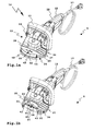
- eine perspektivische teilweise geschnittene Schrägansicht einer Unterseite der Hand-Werkzeugmaschine gemäß der vorgenannten Figuren,
- Fig. 5
- eine Teilansicht der Hand-Werkzeugmaschine gemäß
Figur 4 , jedoch mit leicht verschwenkter Perspektive, und - Fig. 6
- eine weitere Ansicht der Hand-Werkzeugmaschine mit entferntem Abdeckelement und teilweise geschnittenem Werkzeug schräg von vorn.
- Eine in der Zeichnung dargestellte Hand-Werkzeugmaschine 10 ist beispielsweise eine Hand-Schleifmaschine 11. Ein in ein Gehäuse 12 der Hand-Werkzeugmaschine 10 aufgenommener Antriebsmotor 13, vorliegend ein elektrischer Motor, treibt über ein Getriebe 14, zweckmäßigerweise ein Winkelgetriebe, insbesondere ein Kegelradgetriebe, eine Werkzeugspindel 15 an, an deren vorderem freiem Ende eine Werkzeugaufnahme 16 angeordnet ist. Zur elektrischen Stromversorgung kann die Hand-Werkzeugmaschine 10 mittels eines Anschlusskabels 17 an ein Stromversorgungsnetz angeschlossen werden. Es versteht sich, dass alternativ oder ergänzend auch ein Betrieb mittels eines Akkumulator-Speichers oder dergleichen möglich ist.
- Ein Bediener kann die Hand-Werkzeugmaschine 10 beispielsweise an einem von der Werkzeugaufnahme 16 entfernteren Handgriffabschnitt 18 ergreifen, wo ein Schalter 23 zum Ein- und Ausschalten des Antriebsmotors 13 angeordnet ist, sowie optional auch an einem zweckmäßigerweise bügelartigen Handgriff 19, der näher bei der Werkzeugaufnahme 16, beispielsweise oberhalb derselben, angeordnet ist. Der Handgriff 19 ist in der Querschnittsdarstellung gemäß
Figur 2a weggelassen. Der Handgriff 19 ist zweckmäßigerweise schwenkbar und mittels einer Feststellschraube 20 festlegbar, sodass der Bediener die Hand-Werkzeugmaschine 10 optimal an seine ergonomischen Bedürfnisse anpassen kann. Der Bediener kann die Hand-Werkzeugmaschine 10 mit beiden Händen ergreifen und somit sicher führen. - Ein an der Werkzeugaufnahme 16 befestigbares Werkzeug 21 rotiert beim Betrieb der Hand-Werkzeugmaschine 10. Das Werkzeug 21 ist ein Schleif-Werkzeug zur abrasiven Bearbeitung eines Werkobjekts 22 oder einer Werkobjektoberfläche. Im vorliegenden Fall ist die Hand-Schleifmaschine 11 ein Betonschleifer. Das Werkobjekt 22 ist beispielsweise ein Betonboden, eine Betonwand oder dergleichen.
- Es sind also effektive Maßnahmen zweckmäßig, dass das Werkzeug 21 beim Betrieb nicht frei zugänglich ist, sodass Verletzungen des Bedieners vermieden werden.
- Zudem entsteht beim Betrieb des Werkzeugs 21 eine große Menge von Staub, was den Bediener gesundheitlich schädigen kann.
- Die Abdeckvorrichtung 24 umfasst einen Werkzeugraum 26 zur Aufnahme und zum zumindest teilweisen, vorliegend vollständigen Überdecken des Werkzeugs 21. Der Werkzeugraum 26 ist zu einem Großteil in einer Abdeckhaube 25 der Abdeckvorrichtung 24 vorgesehen. Zur im wesentlichen vollständigen Abdeckung eines Seitenrands 28 des Werkzeugs 21 ist eine Seitenrandabdeckung 27 vorgesehen, die das Werkzeug 21 vorliegend ringförmig umgibt. Die Seitenrandabdeckung 27 ist korrespondierend mit dem kreisrunden Außenumfang des Werkzeugs 21, vorliegend einer Schleifscheibe, kreisrund.
- Letztlich ist also das Schleif-Werkzeug 21 entsprechend der Darstellung von beispielsweise
Figur 3b in dem von der Abdeckhaube 25 in der Seitenrandabdeckung 27 begrenzten Werkzeugraum 26 aufgenommen. - Ein Haubenkörper 29 ist mit dem Gehäuse 12 im wesentlichen starr verbunden, beispielsweise mittels Schrauben 30. An der Oberseite des Haubenkörpers 29 sind zweckmäßigerweise Verstärkungsrippen angebracht, was dessen mechanische Stabilität verbessert.
- Das Gehäuse 12 und der Haubenkörper 29 als Hauptbestandteil der Abdeckhaube 25 bilden zweckmäßigerweise eine starre Baueinheit. Hier sei angemerkt, dass selbstverständlich auch eine flexible Lagerung der Abdeckhaube bezüglich des Gehäuses 12 möglich ist oder eine Anordnung getroffen sein kann, bei der der Haubenkörper ein Bestandteil des Gehäuses einer Hand-Werkzeugmaschine bildet. Jedenfalls ist die Position des Werkzeugs 21 bezüglich des Werkzeugraum 26 durch die starre Verbindung des Haubenkörpers 29 mit dem Gehäuse 12 eindeutig festgelegt. Dennoch hat die Abdeckvorrichtung 24 eine Beweglichkeit zur flexiblen Anpassung an einen jeweiligen zu bearbeitenden Untergrund.
- Die Seitenrandabdeckung 27 ist nämlich bezüglich der Abdeckhaube 25, insbesondere bezüglich des Haubenkörpers 29, beweglich gelagert. Ein Basisteil 31 der Seitenrandabdeckung 27 ist mit einer Führung 32 an dem Haubenkörper 29 beweglich gelagert. Die Führung 32 umfasst eine Führungsnut 33 an einem Radialvorsprung 34 eines Abdeckoberteils 35 der Abdeckhaube 25. Das Abdeckoberteil 35 umfasst eine Deck-Wand 36 des Werkzeugraums 26, die der Werkzeug-Oberseite 37 des Werkzeugs 21 zugewandt ist. Der Radialvorsprung 34 bildet sozusagen eine radiale Fortsetzung der Deck-Wand 36 und ist mit dieser einstückig.
- Eine Umfangswand 38 der Abdeckhaube 25 umgibt den Seitenrand 28 des Werkzeugs 21. Die Umfangswand 38 steht in Richtung des Werkzeugs 21 nach unten vor das Abdeckoberteil 35 vor. Die Umfangswand 38 bildet einen einstückigen Bestandteil des Abdeckoberteils 35. Die Umfangswand 38 bildet einen mechanischen Seitenschutz, innerhalb dessen das Werkzeug 21 angeordnet ist.
- Ein Innenumfang des Basisteils 31 liegt mit Bewegungsspiel am Aussenumfang der Umfangswand 38 an, was eine zusätzliche Führung bewirkt.
- Schrauben 39, die in den Schraubaufnahmen 40 des Haubenkörpers 29 eingeschraubt sind, halten die Seitenrandabdeckung 27 an der Abdeckhaube 25. Die Schraubaufnahmen 40 sind beispielsweise zwischen Wandabschnitten der Umfangswand 38 oder neben der Umfangswand 38 angeordnet. Beispielsweise sind drei Schraubaufnahmen 40 im gleichen Abstand zueinander vorgesehen. Jedenfalls haben die Schraubaufnahmen 40 einen derartigen Abstand zu der Seitenrandabdeckung 27 dass Köpfe der Schrauben 39, die in die Schraubaufnahmen 40 eingeschraubt sind, die Seitenrandabdeckung 27 überkragen und sie somit an dem Haubenkörper 29 halten. Zwischen den Schraubenköpfen und der Seitenrandabdeckung 27 ist ein Bewegungsspiel vorgesehen.
- Eine Anlage-Federanordnung 41 mit Federn 42 belastet die Seitenrandabdeckung 27 als Ganzes in Richtung des Werkobjekts 22. Die Federn 42 sind beispielsweise zwischen dem Abdeckoberteil 35, insbesondere dessen Radialvorsprung 34, und dem Basisteil 31 der Seitenrandabdeckung 27 vorgesehen. Beispielsweise sind vier Federn 42 vorgesehen, deren Abstand zueinander zweckmäßigerweise im wesentlichen gleich ist. In
Figur 1b sind die beiden vorderen Federn 42 sichtbar. Um die Seitenrandabdeckung 27 verkantungsfrei und gleichmäßig in Richtung des Werkobjekts 22 zu belasten, sind zweckmäßigerweise auch an der vom Betrachter abgewandten Seite der Seitenrandabdeckung 27 Federn 42 vorgesehen. - Der Radialvorsprung 34 steht als eine Art Kranz vor die Deck-Wand 36 bzw. das Abdeckoberteil 35 vor. Der Radialvorsprung 34 ist im wesentlichen ringförmig und erstreckt sich über den gesamten Außenumfang der Abdeckhaube 25 mit Ausnahme eine vorderen Bereiches.
- Die Seitenrandabdeckung 27 weist ein Abdeckelement 43 auf, das mittels eines Schwenklagers 44 bezüglich der übrigen Komponenten der Abdeckvorrichtung 24 zwischen einer Abdeckstellung A, bei der es den Seitenrand 28 des Werkzeugs 21 abdeckt und einer Offenstellung O verschwenkbar gelagert, in der das Abdeckelement 43 einen Seitenrandabschnitt 45 des Werkzeugs 21 freigibt. Die Umfangswand 38 hat im Bereich des Abdeckelements 43 einen Ausschnitt, durch den das Werkzeug 21 nach vorn aus dem Werkzeugraum 26 vorsteht. Bei hochgeklapptem, in Offenstellung O befindlichen Abdeckelement 43 ist eine optimale Randbearbeitung des Werkobjekts 22 oder einer sonstigen zu bearbeitenden Oberfläche möglich. Ferner ist optional vorgesehen, dass an einer Vorderwand 46 des Basisteils 31 ein Ausschnitt 47 vorgesehen ist, durch den das Werkzeug 21 vorstehen kann.
- Das Schwenklager 44 ist zwischen dem Basisteil 31 und dem Abdeckelement 43 vorgesehen. Somit ist das Abdeckelement 43 einem Basisteil 31 schwenkbar angelenkt und macht dessen Bewegungen mit. Mithin bewegt sich also die Seitenrandabdeckung 27 als Ganzes bezüglich des am Gehäuse 12 fest montierten Haubenkörpers 29, was eine optimale Anpassung an eine Werkobjektkontur ermöglicht.
- Zur flexiblen Anpassung an eine Werkobjektoberfläche oder Bearbeitungsoberfläche trägt auch bei, dass die Seitenrandabdeckung 27 eine flexible Dichtung 48 aufweist. Zwar wäre es möglich, dass die flexible Dichtung 48 zumindest abschnittsweise durch einen Gummiwulst oder dergleichen gebildet ist. Beim Ausführungsbeispiel ist jedoch eine Bürste 49 vorgesehen, die sich nicht nur optimal an einen Untergrund anpasst, sondern zudem noch luftdurchlässig ist, was für eine effektive Staubabfuhr, insbesondere Staubabsaugung, vorteilhaft ist.
- Die Bürste 49 erstreckt sich um den gesamten Umfang der Seitenrandabdeckung 27, sodass sowohl am Basisteil 31 als auch am Abdeckelement 43 Borsten vorgesehen sind.
- Die Bürste 49 bildet eine Art Bürstenkranz, die den Werkzeugraum 26 ringförmig umgibt.
- Die Anlage-Federanordnung 41 drückt die Seitenrandabdeckung 27 von der Abdeckhaube 25 weg, sodass die Dichtung 48 vor die Umfangswand 38 vorsteht (
Fig. 3b ,4 ). Die Seitenrandabdeckung 27 einschließlich des Bürstkranzes mit der Bürste 49 hat ein geringes Gewicht, sodass sie bezüglich der übrigen Komponenten der Hand-Werkzeugmaschine 10, insbesondere des Gehäuses 12 leicht bewegbar ist und eine optimale Anpassung an einen zu bearbeitenden Untergrund gelingt. Wenn beispielsweise ein Fußboden bearbeitet werden soll, die Hand-Werkzeugmaschine beispielsweise die inFigur 3b angezeigte Lage einnimmt, genügt an sich schon die Gewichtskraft der auf der Anlage-Federanordnung 41 auflastenden Komponenten dazu, dass die Seitenrandabdeckung 27 in Richtung der Abdeckhaube 25 bewegt wird, und Abrasiv-Vorsprünge 50 an einer Bearbeitungsseite 51 des Werkzeugs 21 in Kontakt mit einem zu bearbeitenden Werkobjekt gelangen (Figur 3b ). - Eine nicht dargestellte Alternative könnte vorsehen, dass ein Abdeckelement in der Art des Abdeckelements 43 schwenkbar an einem feststehenden Bauteil einer Hand-Werkzeugmaschine gelagert ist. Zweckmäßigerweise ist auch dann vorgesehen, dass das Abdeckelement bezüglich des feststehenden Teils, insbesondere schwimmend, beweglich ist, etwa in der Art der Seitenrandabdeckung 27.
- Das Abdeckelement 43 ist kippstabil in der Offenstellung O oder der Abdeckstellung A. Das Abdeckelement43 kippt über eine Totpunktlage (
Figur 2a ) entweder in die Abdeckstellung A (Figur 2b ) oder in die Offenstellung O (Figur 2c ). Der Bediener der Hand-Werkzeugmaschine 10 muss also das Abdeckelement 43 nicht in der Offenstellung O oder Abdeckstellung A halten. Das Abdeckelement 43 nimmt die jeweilige Lage selbsttätig ein. Zusätzlich könnte zum Halten des Abdeckelements 43 in der jeweiligen Lage eine Verrastung, eine Magnethalterung oder dergleichen vorgesehen sein. - Bei der Hand-Werkzeugmaschine 10 ist jedoch eine andere Maßnahme getroffen: Eine Federanordnung 52 mit einer Feder 53 hält das Abdeckelement 43 in der Abdeckstellung A oder der Offenstellung O. Die Feder 42 ist einerseits am Basisteil 31 mit einer Federhalterung 54 und andererseits an dem Abdeckelement 43 mittels einer Federhalterung 55 angelenkt. Die Federhalterung 55 ist etwa im Bereich einer Schwenkachse des Schwenklagers 44 vorgesehen. Die Feder 53 ist beispielsweise zwischen zwei Schwenklagerteilen des Schwenklagers 44 angeordnet. Die Federhalterung 55 schwenkt sozusagen um die Federhalterung 54 zwischen der Abdeckstellung A und der Offenstellung O über die Totpunktlage gemäß
Figur 2a hinweg. Durch die Federanordnung 52 wird das Abdeckelement 43 sicher in der Offenstellung O oder Abdeckstellung A gehalten. Die Bedienung ist besonders einfach. Zweckmäßigerweise ist für die Feder 53 eine Ausnehmung 56 an dem Abdeckelement 43 vorgesehen. - Zu einer effektiven Staubabfuhr, insbesondere Staubabsaugung, aus dem Werkzeugraum 26 ist ein innovatives Abfuhrkonzept oder Absaugkonzept vorgesehen:
- An der Abdeckhaube 25 ist ein Staubabfuhranschluss 60 zum Anschluss eines staubabsaugenden Gerätes, eines Staubsackes oder dergleichen vorgesehen. Der Staubabfuhranschluss 60 enthält beispielsweise einen Anschlussstutzen 61, der vor eine Außenseite der Abdeckhaube 25 vorsteht.
- In dem Werkzeugraum 26 ist zwischen dem Werkzeug 21 und einer Wand des Werkzeugraums 26 ein Staubabfuhrkanal 62 gebildet, der zu einer Einlassöffnung 63 des Staubabfuhranschlusses 60 führt. Ein Strömungsquerschnitt des Staubabfuhrkanals 62 nimmt von dessen Anfang 64 bis zu der Einlassöffnung 63 zu. Dadurch ist nicht nur im Bereich der Einlassöffnung 63, d.h. am Auslass für einen Staubluftstrom 65, ein optimaler Abführoder Absaugeffekt erzielbar, sondern auch am Anfang 64 des Staubabfuhrkanals 62.
- Der Staubabfuhrkanal 62 verläuft spiralig um die Werkzeugspindel 15 herum.
- Der Staubabfuhrkanal 62 ist zwischen der Werkzeugoberseite 37 des Werkzeugs 21 und der dieser zugewandten Deck-Wand 36 des Werkzeugraums 26 vorgesehen. Die Deck-Wand 36 ist zweckmäßigerweise plan, was ein optimales Strömungsverhalten ermöglicht.
- Seitlich wird der Staubabfuhrkanal 62 durch die Seitenwand/Umfangswand 38 begrenzt. Allerdings ist zwischen der Umfangswand 38 und dem Seitenrand 28 des Werkzeugs 21 ein Spalt vorhanden, durch den Luft in den Staubabfuhrkanal 62 strömen kann. Diese zuströmende Luft strömt durch die luftdurchlässige Dichtung 48, vorliegend die Bürste 49, hindurch und an der unteren Stirnseite der Seitenwand/Umfangswand 38 vorbei in den Staubabfuhrkanal 62 ein.
- Zu dem sind Luft-Durchlassöffnungen 66 am Werkzeug 21 vorgesehen, durch die Luft in den Staubabfuhrkanal 62 einströmen kann. Die Luft-Durchlassöffnungen 66 erstrecken sich von der Bearbeitungsseite 51 des Werkzeugs 21 zu dessen Oberseite 37.
- Eine Drehrichtung des Werkzeugs 21 entspricht einer Strömungsrichtung des Staubluftstroms 65, was dessen Strömung verstärkt. Der Staubluftstrom 65 ist als Pfeil eingezeichnet, der die Strömungsrichtung des Staubluftstroms 65 anzeigt.
- Die Deck-Wand 36 kann vorteilhaft ein Plattenbauteil sein, beispielsweise aus Kunststoff, das an die Innenseite zur Bildung einer oberen Wand des Werkzeugraums 26 an den Haubenkörper angeschraubt ist. Selbstverständlich kann die Deck-Wand 36 auch einen integralen Bestandteil des Haubenkörpers 29 bilden.
- Die Dichtung 48 bzw. Bürste 49 ist luftdurchlässig. Dadurch ist es möglich, dass Zuluft 67 durch die Borsten der Bürste 49 hindurch und an den vorderen, freien Seite der Umfangswand 38 vorbei in den Staubabfuhrkanal 62 einströmen kann, wobei diese Zuluft in den Ringspalt zwischen der Umfangswand 38 und dem Seitenrand des Werkzeugs 21 und durch die Luft-Durchlassöffnungen 66 am Werkzeug 21 strömt. Die Umfangswand 38 ist bei diesem innovativen Konzept insofern vorteilhaft, als sie den Staubabfuhrkanal 62 seitlich begrenzt und somit ein optimales Strömen in Richtung der Einlassöffnung 63 ermöglicht. Dabei kann die Zuluft 67 dennoch ungehindert einströmen, sodass kein strömungshindernder Unterdruck entsteht.
Claims (15)
- Hand-Werkzeugmaschine, insbesondere Hand-Schleifmaschine (11), mit einer durch einen Antriebsmotor antreibbaren Werkzeugaufnahme (16) für ein Werkzeug (21), insbesondere ein Schleif-Werkzeug, zur abrasiven Bearbeitung eines Werkobjekts (22) und einer Abdeckvorrichtung (24) zum Abdecken des Werkzeugs (21), wobei die Abdeckvorrichtung (24) eine Seitenrandabdeckung (27) zum Abdecken eines Seitenrands (28) des Werkzeugs (21) aufweist, und wobei ein Abdeckelement (43) der Seitenrandabdeckung (27) zwischen einer einen Seitenrandabschnitt (45) des Werkzeugs (21) freigebenden Offenstellung (O) und einer den Seitenrandabschnitt (45) des Werkzeugs (21) verdeckenden Abdeckstellung (A) beweglich gelagert ist, dadurch gekennzeichnet, dass das Abdeckelement (43) an einem Schwenklager (44) zwischen der Abdeckstellung (A) und der Offenstellung (O) schwenkbar gelagert ist.
- Hand-Werkzeugmaschine nach Anspruch 1, dadurch gekennzeichnet, dass das Abdeckelement (43) in der Offenstellung (O) und/oder der Abdeckstellung (A) eine kippstabile Lage einnimmt.
- Hand-Werkzeugmaschine nach Anspruch 1 oder 2, dadurch gekennzeichnet, dass sie eine Federanordnung (52) zum Halten des Abdeckelements (43) in der Offenstellung (O) und/oder der Abdeckstellung (A) aufweist.
- Hand-Werkzeugmaschine nach einem der vorhergehenden Ansprüche, dadurch gekennzeichnet, dass die Seitenrandabdeckung (27), insbesondere das Abdeckelement (43), an einer zur Anlage an dem Werkobjekt (22) vorgesehenen Anlageseite eine flexible Dichtung (48) zumindest an einem Teilumfang aufweist.
- Hand-Werkzeugmaschine nach Anspruch 4, dadurch gekennzeichnet, dass die flexible Dichtung (48) luftdurchlässig ist und/oder eine Bürste (49) umfasst.
- Hand-Werkzeugmaschine nach einem der vorhergehenden Ansprüche, dadurch gekennzeichnet, dass das Abdeckelement (43) an einem Basisteil (31) der Seitenrandabdeckung (27) beweglich gelagert ist.
- Hand-Werkzeugmaschine nach einem der vorhergehenden Ansprüche, dadurch gekennzeichnet, dass die Seitenrandabdeckung (27) als Ganzes und/oder das Abdeckelement (43) zur Anlage an dem Werkobjekt (22) bezüglich eines eine Oberseite des Werkzeugs (21) zumindest teilweise abdeckenden Abdeckoberteils beweglich gelagert sind.
- Hand-Werkzeugmaschine nach einem der vorhergehenden Ansprüche, dadurch gekennzeichnet, dass sie eine Anlage-Federanordnung (41) zur Belastung der Seitenrandabdeckung (27) als Ganzes und/oder des Abdeckelements (43) in Richtung des Werkobjekts (22) aufweist.
- Hand-Werkzeugmaschine nach einem der vorhergehenden Ansprüche, dadurch gekennzeichnet, dass die Seitenrandabdeckung (27) einen das Werkzeug (21) ringförmig umgebenden Abdeckring umfasst und das Abdeckelement (43) ein Ringsegmentteil des Abdeckrings bildet.
- Hand-Werkzeugmaschine nach einem der vorhergehenden Ansprüche, dadurch gekennzeichnet, dass der Seitenrandabdeckung (27) im wesentlichen kreisringförmig ist.
- Hand-Werkzeugmaschine nach einem der vorhergehenden Ansprüche, dadurch gekennzeichnet, dass die Abdeckvorrichtung (24) eine Abdeckhaube (25) mit einem Werkzeugraum (26) zur Aufnahme und zum zumindest teilweisen Überdecken des Werkzeugs (21) umfasst oder bildet.
- Hand-Werkzeugmaschine nach einem der vorhergehenden Ansprüche, dadurch gekennzeichnet, dass die Seitenrandabdeckung (27) einen Bestandteil einer Seitenwand des Werkzeugraums (26) bildet und/oder neben einer Seitenwand (38) der Abdeckhaube (25) verläuft, wobei die Seitenrandabdeckung (27) zweckmäßigerweise in Richtung des Werkobjekts (22) vor die Seitenwand (38) vorsteht.
- Hand-Werkzeugmaschine nach einem der vorhergehenden Ansprüche, dadurch gekennzeichnet, dass die Abdeckvorrichtung (24) einen Staubabfuhranschluss (60) zum Abführen von beim Betrieb des Werkzeugs (21) anfallendem Staub aus einem das Werkzeug (21) aufnehmenden Werkzeugraum (26) der Abdeckvorrichtung (24) aufweist.
- Hand-Werkzeugmaschine nach Anspruch 13, dadurch gekennzeichnet, dass zwischen dem Werkzeug (21) und einer Wand des Werkzeugraums (26) ein zu einer Einlassöffnung (63) des Staubabfuhranschlusses (60) führender Staubabfuhrkanal (62) gebildet ist, und dass ein Strömungsquerschnitt des Staubabfuhrkanals (62) zu der Einlassöffnung (63) hin, insbesondere kontinuierlich, zunimmt.
- Hand-Werkzeugmaschine nach einem der vorhergehenden Ansprüche, dadurch gekennzeichnet, dass der Antriebsmotor zum rotatorischen Antreiben des Werkzeugs (21) ausgestaltet ist und/oder dass das Werkzeug (21) eine Schleifscheibe und/oder ein Schleifpad umfasst und/oder dass die Hand-Werkzeugmaschine (10) eine Beton-Schleifmaschine ist.
Applications Claiming Priority (1)
| Application Number | Priority Date | Filing Date | Title |
|---|---|---|---|
| DE102008046948A DE102008046948A1 (de) | 2008-09-12 | 2008-09-12 | Hand-Werkzeugmaschine mit einer Seitenrandabdeckung |
Publications (3)
| Publication Number | Publication Date |
|---|---|
| EP2163344A2 true EP2163344A2 (de) | 2010-03-17 |
| EP2163344A3 EP2163344A3 (de) | 2013-05-29 |
| EP2163344B1 EP2163344B1 (de) | 2014-11-19 |
Family
ID=41328643
Family Applications (1)
| Application Number | Title | Priority Date | Filing Date |
|---|---|---|---|
| EP20090008603 Active EP2163344B1 (de) | 2008-09-12 | 2009-07-01 | Hand-Werkzeugmaschine mit einer Seitenrandabdeckung |
Country Status (2)
| Country | Link |
|---|---|
| EP (1) | EP2163344B1 (de) |
| DE (1) | DE102008046948A1 (de) |
Cited By (2)
| Publication number | Priority date | Publication date | Assignee | Title |
|---|---|---|---|---|
| US9289879B2 (en) | 2013-05-02 | 2016-03-22 | Black & Decker Inc. | Hinge assembly for an angle grinder dust shroud |
| WO2019211269A1 (de) * | 2018-05-04 | 2019-11-07 | Robert Bosch Gmbh | Einfach montierbare staubabsaugung |
Families Citing this family (3)
| Publication number | Priority date | Publication date | Assignee | Title |
|---|---|---|---|---|
| JP6531337B1 (ja) * | 2018-10-06 | 2019-06-19 | 株式会社ナカヤ | 粉塵制御機能付電動研削機 |
| DE102022134161A1 (de) | 2021-12-22 | 2023-06-22 | Festool Gmbh | Hand-Werkzeugmaschine mit in Winkelpositionen montierbarem Handgriffgehäuseteil |
| DE102021134361A1 (de) | 2021-12-22 | 2023-06-22 | Festool Gmbh | Hand-Werkzeugmaschine mit einem Stromversorgungsanschluss |
Citations (2)
| Publication number | Priority date | Publication date | Assignee | Title |
|---|---|---|---|---|
| EP0267993A1 (de) | 1986-11-17 | 1988-05-25 | Jerome Roestenberg | Schutzhaube für Handschleifer |
| WO1997032692A1 (de) | 1996-03-06 | 1997-09-12 | Ulrich Wagner | Auf handschleif- und poliermaschine dichtend aufsetzbare schutz- und absaughaube |
Family Cites Families (6)
| Publication number | Priority date | Publication date | Assignee | Title |
|---|---|---|---|---|
| US3987589A (en) * | 1972-08-02 | 1976-10-26 | Miksa Marton | Vacuum attachment for abrading machine |
| DE8815327U1 (de) * | 1988-12-09 | 1989-03-23 | Gateway Werkzeug- Und Maschinen Vertriebs Gmbh, 4240 Emmerich, De | |
| DE4306009C2 (de) * | 1993-02-26 | 1996-05-09 | Fein C & E | Absaugeinrichtung für eine Flächenschleifmaschine |
| CH692547A5 (de) * | 1998-03-17 | 2002-07-31 | Air Tec Ag | Staubschutzhaube zu Schleiffräsen. |
| FR2882949B3 (fr) * | 2005-03-14 | 2007-02-02 | M B H Dev Sarl | Ponceuse-meuleuse aspirante ou non |
| DE102006041671B4 (de) * | 2006-09-06 | 2018-03-29 | Robert Bosch Gmbh | Schutzhaube einer Handwerkzeugmaschine |
-
2008
- 2008-09-12 DE DE102008046948A patent/DE102008046948A1/de not_active Withdrawn
-
2009
- 2009-07-01 EP EP20090008603 patent/EP2163344B1/de active Active
Patent Citations (2)
| Publication number | Priority date | Publication date | Assignee | Title |
|---|---|---|---|---|
| EP0267993A1 (de) | 1986-11-17 | 1988-05-25 | Jerome Roestenberg | Schutzhaube für Handschleifer |
| WO1997032692A1 (de) | 1996-03-06 | 1997-09-12 | Ulrich Wagner | Auf handschleif- und poliermaschine dichtend aufsetzbare schutz- und absaughaube |
Cited By (3)
| Publication number | Priority date | Publication date | Assignee | Title |
|---|---|---|---|---|
| US9289879B2 (en) | 2013-05-02 | 2016-03-22 | Black & Decker Inc. | Hinge assembly for an angle grinder dust shroud |
| WO2019211269A1 (de) * | 2018-05-04 | 2019-11-07 | Robert Bosch Gmbh | Einfach montierbare staubabsaugung |
| CN112074376A (zh) * | 2018-05-04 | 2020-12-11 | 罗伯特·博世有限公司 | 能简单装配的吸尘装置 |
Also Published As
| Publication number | Publication date |
|---|---|
| EP2163344B1 (de) | 2014-11-19 |
| EP2163344A3 (de) | 2013-05-29 |
| DE102008046948A1 (de) | 2010-03-18 |
Similar Documents
| Publication | Publication Date | Title |
|---|---|---|
| EP2163356B1 (de) | Hand-Werkzeugmaschine mit einer Abdeckhaube und einem Staubabfuhranschluss | |
| EP1116551B1 (de) | Handgeführtes Schleifgerät | |
| EP2163344B1 (de) | Hand-Werkzeugmaschine mit einer Seitenrandabdeckung | |
| WO2003004217A1 (de) | Schutzvorrichtung für eine handwerkzeugmaschine | |
| EP1321228B1 (de) | Schleifgerät mit Absaughaube | |
| EP2965865B1 (de) | Hand-trenngerät | |
| DE19513279A1 (de) | Staubsammelsystem für ein maschinell angetriebenes Werkzeug | |
| DE2427450B2 (de) | Staubsaugvorrichtung | |
| WO2006072504A2 (de) | Handwerkzeugmaschine mit einem führungskanal | |
| DE102008002548B4 (de) | Werkzeugmaschine, insbesondere Handwerkzeugmaschine | |
| EP1422032A1 (de) | Elektrohandwerkzeugmaschine | |
| EP1368156A1 (de) | Handwerkzeugmaschine mit einer schwenkbaren werkzeugabdeckung | |
| EP2106327B1 (de) | Handgeführte werkzeugmaschine | |
| DE102010047529A1 (de) | Trennschleifgerät mit Staubabsaugung | |
| DE602004011029T2 (de) | Bandschleifmaschine | |
| DE3919701A1 (de) | Handschleifmaschine | |
| EP0558893A2 (de) | Als Handgerät ausgebildetes, motorisch angetriebenes Gerät zum Schleifen, Polieren, Entrosten oder dergleichen Bearbeitung von Oberflächen | |
| EP3209464A1 (de) | Handwerkzeugmaschine mit einer sds-werkzeugaufnahme | |
| DE1121968B (de) | Schutz- und Absaugegehaeuse fuer Handschleif- oder dergleichen Maschinen | |
| WO2020002049A1 (de) | Schleifblock zur manuellen anwendung sowie system umfassend schleifblock und schleifartikel | |
| EP0569360A1 (de) | Handwerkzeugmaschine | |
| DE102014200511A1 (de) | Handwerkzeugmaschine mit einer Absaughaube | |
| DE202012008297U1 (de) | Schleifeinheit | |
| EP2123398B1 (de) | Handwerkzeug zur materialabtragenden Bearbeitung einer Werkstück- oder Bauteiloberfläche | |
| EP0573826A1 (de) | Motorgetriebener Handbandschleifer |
Legal Events
| Date | Code | Title | Description |
|---|---|---|---|
| PUAI | Public reference made under article 153(3) epc to a published international application that has entered the european phase |
Free format text: ORIGINAL CODE: 0009012 |
|
| AK | Designated contracting states |
Kind code of ref document: A2 Designated state(s): AT BE BG CH CY CZ DE DK EE ES FI FR GB GR HR HU IE IS IT LI LT LU LV MC MK MT NL NO PL PT RO SE SI SK SM TR |
|
| AX | Request for extension of the european patent |
Extension state: AL BA RS |
|
| RAP1 | Party data changed (applicant data changed or rights of an application transferred) |
Owner name: FESTOOL GROUP GMBH & CO. KG |
|
| PUAL | Search report despatched |
Free format text: ORIGINAL CODE: 0009013 |
|
| AK | Designated contracting states |
Kind code of ref document: A3 Designated state(s): AT BE BG CH CY CZ DE DK EE ES FI FR GB GR HR HU IE IS IT LI LT LU LV MC MK MT NL NO PL PT RO SE SI SK SM TR |
|
| AX | Request for extension of the european patent |
Extension state: AL BA RS |
|
| RIC1 | Information provided on ipc code assigned before grant |
Ipc: B24B 23/02 20060101AFI20130425BHEP Ipc: B24B 55/05 20060101ALI20130425BHEP Ipc: B24B 55/10 20060101ALI20130425BHEP |
|
| 17P | Request for examination filed |
Effective date: 20131004 |
|
| RBV | Designated contracting states (corrected) |
Designated state(s): AT BE BG CH CY CZ DE DK EE ES FI FR GB GR HR HU IE IS IT LI LT LU LV MC MK MT NL NO PL PT RO SE SI SK SM TR |
|
| 17Q | First examination report despatched |
Effective date: 20131030 |
|
| GRAP | Despatch of communication of intention to grant a patent |
Free format text: ORIGINAL CODE: EPIDOSNIGR1 |
|
| INTG | Intention to grant announced |
Effective date: 20140616 |
|
| RAP1 | Party data changed (applicant data changed or rights of an application transferred) |
Owner name: FESTOOL GMBH |
|
| GRAS | Grant fee paid |
Free format text: ORIGINAL CODE: EPIDOSNIGR3 |
|
| GRAA | (expected) grant |
Free format text: ORIGINAL CODE: 0009210 |
|
| AK | Designated contracting states |
Kind code of ref document: B1 Designated state(s): AT BE BG CH CY CZ DE DK EE ES FI FR GB GR HR HU IE IS IT LI LT LU LV MC MK MT NL NO PL PT RO SE SI SK SM TR |
|
| REG | Reference to a national code |
Ref country code: GB Ref legal event code: FG4D Free format text: NOT ENGLISH |
|
| REG | Reference to a national code |
Ref country code: CH Ref legal event code: EP |
|
| REG | Reference to a national code |
Ref country code: AT Ref legal event code: REF Ref document number: 696709 Country of ref document: AT Kind code of ref document: T Effective date: 20141215 |
|
| REG | Reference to a national code |
Ref country code: IE Ref legal event code: FG4D Free format text: LANGUAGE OF EP DOCUMENT: GERMAN |
|
| REG | Reference to a national code |
Ref country code: DE Ref legal event code: R096 Ref document number: 502009010231 Country of ref document: DE Effective date: 20141231 |
|
| REG | Reference to a national code |
Ref country code: NL Ref legal event code: VDEP Effective date: 20141119 |
|
| REG | Reference to a national code |
Ref country code: LT Ref legal event code: MG4D |
|
| PG25 | Lapsed in a contracting state [announced via postgrant information from national office to epo] |
Ref country code: IS Free format text: LAPSE BECAUSE OF FAILURE TO SUBMIT A TRANSLATION OF THE DESCRIPTION OR TO PAY THE FEE WITHIN THE PRESCRIBED TIME-LIMIT Effective date: 20150319 Ref country code: FI Free format text: LAPSE BECAUSE OF FAILURE TO SUBMIT A TRANSLATION OF THE DESCRIPTION OR TO PAY THE FEE WITHIN THE PRESCRIBED TIME-LIMIT Effective date: 20141119 Ref country code: NL Free format text: LAPSE BECAUSE OF FAILURE TO SUBMIT A TRANSLATION OF THE DESCRIPTION OR TO PAY THE FEE WITHIN THE PRESCRIBED TIME-LIMIT Effective date: 20141119 Ref country code: LT Free format text: LAPSE BECAUSE OF FAILURE TO SUBMIT A TRANSLATION OF THE DESCRIPTION OR TO PAY THE FEE WITHIN THE PRESCRIBED TIME-LIMIT Effective date: 20141119 Ref country code: PT Free format text: LAPSE BECAUSE OF FAILURE TO SUBMIT A TRANSLATION OF THE DESCRIPTION OR TO PAY THE FEE WITHIN THE PRESCRIBED TIME-LIMIT Effective date: 20150319 Ref country code: ES Free format text: LAPSE BECAUSE OF FAILURE TO SUBMIT A TRANSLATION OF THE DESCRIPTION OR TO PAY THE FEE WITHIN THE PRESCRIBED TIME-LIMIT Effective date: 20141119 Ref country code: NO Free format text: LAPSE BECAUSE OF FAILURE TO SUBMIT A TRANSLATION OF THE DESCRIPTION OR TO PAY THE FEE WITHIN THE PRESCRIBED TIME-LIMIT Effective date: 20150219 |
|
| PG25 | Lapsed in a contracting state [announced via postgrant information from national office to epo] |
Ref country code: GR Free format text: LAPSE BECAUSE OF FAILURE TO SUBMIT A TRANSLATION OF THE DESCRIPTION OR TO PAY THE FEE WITHIN THE PRESCRIBED TIME-LIMIT Effective date: 20150220 Ref country code: CY Free format text: LAPSE BECAUSE OF FAILURE TO SUBMIT A TRANSLATION OF THE DESCRIPTION OR TO PAY THE FEE WITHIN THE PRESCRIBED TIME-LIMIT Effective date: 20141119 Ref country code: HR Free format text: LAPSE BECAUSE OF FAILURE TO SUBMIT A TRANSLATION OF THE DESCRIPTION OR TO PAY THE FEE WITHIN THE PRESCRIBED TIME-LIMIT Effective date: 20141119 Ref country code: LV Free format text: LAPSE BECAUSE OF FAILURE TO SUBMIT A TRANSLATION OF THE DESCRIPTION OR TO PAY THE FEE WITHIN THE PRESCRIBED TIME-LIMIT Effective date: 20141119 Ref country code: PL Free format text: LAPSE BECAUSE OF FAILURE TO SUBMIT A TRANSLATION OF THE DESCRIPTION OR TO PAY THE FEE WITHIN THE PRESCRIBED TIME-LIMIT Effective date: 20141119 Ref country code: SE Free format text: LAPSE BECAUSE OF FAILURE TO SUBMIT A TRANSLATION OF THE DESCRIPTION OR TO PAY THE FEE WITHIN THE PRESCRIBED TIME-LIMIT Effective date: 20141119 |
|
| PG25 | Lapsed in a contracting state [announced via postgrant information from national office to epo] |
Ref country code: RO Free format text: LAPSE BECAUSE OF FAILURE TO SUBMIT A TRANSLATION OF THE DESCRIPTION OR TO PAY THE FEE WITHIN THE PRESCRIBED TIME-LIMIT Effective date: 20141119 Ref country code: SK Free format text: LAPSE BECAUSE OF FAILURE TO SUBMIT A TRANSLATION OF THE DESCRIPTION OR TO PAY THE FEE WITHIN THE PRESCRIBED TIME-LIMIT Effective date: 20141119 Ref country code: DK Free format text: LAPSE BECAUSE OF FAILURE TO SUBMIT A TRANSLATION OF THE DESCRIPTION OR TO PAY THE FEE WITHIN THE PRESCRIBED TIME-LIMIT Effective date: 20141119 Ref country code: CZ Free format text: LAPSE BECAUSE OF FAILURE TO SUBMIT A TRANSLATION OF THE DESCRIPTION OR TO PAY THE FEE WITHIN THE PRESCRIBED TIME-LIMIT Effective date: 20141119 Ref country code: EE Free format text: LAPSE BECAUSE OF FAILURE TO SUBMIT A TRANSLATION OF THE DESCRIPTION OR TO PAY THE FEE WITHIN THE PRESCRIBED TIME-LIMIT Effective date: 20141119 |
|
| REG | Reference to a national code |
Ref country code: DE Ref legal event code: R097 Ref document number: 502009010231 Country of ref document: DE |
|
| PLBE | No opposition filed within time limit |
Free format text: ORIGINAL CODE: 0009261 |
|
| STAA | Information on the status of an ep patent application or granted ep patent |
Free format text: STATUS: NO OPPOSITION FILED WITHIN TIME LIMIT |
|
| 26N | No opposition filed |
Effective date: 20150820 |
|
| PG25 | Lapsed in a contracting state [announced via postgrant information from national office to epo] |
Ref country code: IT Free format text: LAPSE BECAUSE OF FAILURE TO SUBMIT A TRANSLATION OF THE DESCRIPTION OR TO PAY THE FEE WITHIN THE PRESCRIBED TIME-LIMIT Effective date: 20141119 |
|
| PG25 | Lapsed in a contracting state [announced via postgrant information from national office to epo] |
Ref country code: SI Free format text: LAPSE BECAUSE OF FAILURE TO SUBMIT A TRANSLATION OF THE DESCRIPTION OR TO PAY THE FEE WITHIN THE PRESCRIBED TIME-LIMIT Effective date: 20141119 Ref country code: MC Free format text: LAPSE BECAUSE OF FAILURE TO SUBMIT A TRANSLATION OF THE DESCRIPTION OR TO PAY THE FEE WITHIN THE PRESCRIBED TIME-LIMIT Effective date: 20141119 |
|
| REG | Reference to a national code |
Ref country code: CH Ref legal event code: PL |
|
| PG25 | Lapsed in a contracting state [announced via postgrant information from national office to epo] |
Ref country code: LU Free format text: LAPSE BECAUSE OF FAILURE TO SUBMIT A TRANSLATION OF THE DESCRIPTION OR TO PAY THE FEE WITHIN THE PRESCRIBED TIME-LIMIT Effective date: 20150701 |
|
| REG | Reference to a national code |
Ref country code: IE Ref legal event code: MM4A |
|
| PG25 | Lapsed in a contracting state [announced via postgrant information from national office to epo] |
Ref country code: CH Free format text: LAPSE BECAUSE OF NON-PAYMENT OF DUE FEES Effective date: 20150731 Ref country code: LI Free format text: LAPSE BECAUSE OF NON-PAYMENT OF DUE FEES Effective date: 20150731 |
|
| REG | Reference to a national code |
Ref country code: FR Ref legal event code: PLFP Year of fee payment: 8 |
|
| PG25 | Lapsed in a contracting state [announced via postgrant information from national office to epo] |
Ref country code: IE Free format text: LAPSE BECAUSE OF NON-PAYMENT OF DUE FEES Effective date: 20150701 |
|
| REG | Reference to a national code |
Ref country code: AT Ref legal event code: MM01 Ref document number: 696709 Country of ref document: AT Kind code of ref document: T Effective date: 20150701 |
|
| PG25 | Lapsed in a contracting state [announced via postgrant information from national office to epo] |
Ref country code: AT Free format text: LAPSE BECAUSE OF NON-PAYMENT OF DUE FEES Effective date: 20150701 |
|
| PG25 | Lapsed in a contracting state [announced via postgrant information from national office to epo] |
Ref country code: MT Free format text: LAPSE BECAUSE OF FAILURE TO SUBMIT A TRANSLATION OF THE DESCRIPTION OR TO PAY THE FEE WITHIN THE PRESCRIBED TIME-LIMIT Effective date: 20141119 |
|
| REG | Reference to a national code |
Ref country code: FR Ref legal event code: PLFP Year of fee payment: 9 |
|
| PG25 | Lapsed in a contracting state [announced via postgrant information from national office to epo] |
Ref country code: HU Free format text: LAPSE BECAUSE OF FAILURE TO SUBMIT A TRANSLATION OF THE DESCRIPTION OR TO PAY THE FEE WITHIN THE PRESCRIBED TIME-LIMIT; INVALID AB INITIO Effective date: 20090701 Ref country code: SM Free format text: LAPSE BECAUSE OF FAILURE TO SUBMIT A TRANSLATION OF THE DESCRIPTION OR TO PAY THE FEE WITHIN THE PRESCRIBED TIME-LIMIT Effective date: 20141119 Ref country code: BG Free format text: LAPSE BECAUSE OF FAILURE TO SUBMIT A TRANSLATION OF THE DESCRIPTION OR TO PAY THE FEE WITHIN THE PRESCRIBED TIME-LIMIT Effective date: 20141119 |
|
| PG25 | Lapsed in a contracting state [announced via postgrant information from national office to epo] |
Ref country code: BE Free format text: LAPSE BECAUSE OF NON-PAYMENT OF DUE FEES Effective date: 20150731 |
|
| PG25 | Lapsed in a contracting state [announced via postgrant information from national office to epo] |
Ref country code: TR Free format text: LAPSE BECAUSE OF FAILURE TO SUBMIT A TRANSLATION OF THE DESCRIPTION OR TO PAY THE FEE WITHIN THE PRESCRIBED TIME-LIMIT Effective date: 20141119 |
|
| REG | Reference to a national code |
Ref country code: FR Ref legal event code: PLFP Year of fee payment: 10 |
|
| PG25 | Lapsed in a contracting state [announced via postgrant information from national office to epo] |
Ref country code: MK Free format text: LAPSE BECAUSE OF FAILURE TO SUBMIT A TRANSLATION OF THE DESCRIPTION OR TO PAY THE FEE WITHIN THE PRESCRIBED TIME-LIMIT Effective date: 20141119 |
|
| P01 | Opt-out of the competence of the unified patent court (upc) registered |
Effective date: 20230517 |
|
| PGFP | Annual fee paid to national office [announced via postgrant information from national office to epo] |
Ref country code: FR Payment date: 20230601 Year of fee payment: 15 |
|
| PGFP | Annual fee paid to national office [announced via postgrant information from national office to epo] |
Ref country code: GB Payment date: 20230601 Year of fee payment: 15 |
|
| PGFP | Annual fee paid to national office [announced via postgrant information from national office to epo] |
Ref country code: DE Payment date: 20230614 Year of fee payment: 15 |