EP2163344A2 - Machine-outil manuelle dotée d'un recouvrement de bord latéral - Google Patents
Machine-outil manuelle dotée d'un recouvrement de bord latéral Download PDFInfo
- Publication number
- EP2163344A2 EP2163344A2 EP09008603A EP09008603A EP2163344A2 EP 2163344 A2 EP2163344 A2 EP 2163344A2 EP 09008603 A EP09008603 A EP 09008603A EP 09008603 A EP09008603 A EP 09008603A EP 2163344 A2 EP2163344 A2 EP 2163344A2
- Authority
- EP
- European Patent Office
- Prior art keywords
- cover
- tool
- side edge
- machine tool
- covering
- Prior art date
- Legal status (The legal status is an assumption and is not a legal conclusion. Google has not performed a legal analysis and makes no representation as to the accuracy of the status listed.)
- Granted
Links
- 239000000428 dust Substances 0.000 claims description 38
- 238000003754 machining Methods 0.000 claims description 4
- 238000007599 discharging Methods 0.000 claims description 2
- 230000003750 conditioning effect Effects 0.000 claims 1
- 230000002093 peripheral effect Effects 0.000 description 16
- 238000007789 sealing Methods 0.000 description 6
- 230000006978 adaptation Effects 0.000 description 4
- 239000011324 bead Substances 0.000 description 4
- 238000000605 extraction Methods 0.000 description 4
- 239000000758 substrate Substances 0.000 description 3
- 230000006378 damage Effects 0.000 description 2
- 230000035699 permeability Effects 0.000 description 2
- 239000004033 plastic Substances 0.000 description 2
- 229910003460 diamond Inorganic materials 0.000 description 1
- 239000010432 diamond Substances 0.000 description 1
- 230000000694 effects Effects 0.000 description 1
- 238000003780 insertion Methods 0.000 description 1
- 230000037431 insertion Effects 0.000 description 1
- 239000000463 material Substances 0.000 description 1
- 239000002184 metal Substances 0.000 description 1
- 238000005498 polishing Methods 0.000 description 1
- 230000001681 protective effect Effects 0.000 description 1
- 230000003014 reinforcing effect Effects 0.000 description 1
Images


Classifications
-
- B—PERFORMING OPERATIONS; TRANSPORTING
- B24—GRINDING; POLISHING
- B24B—MACHINES, DEVICES, OR PROCESSES FOR GRINDING OR POLISHING; DRESSING OR CONDITIONING OF ABRADING SURFACES; FEEDING OF GRINDING, POLISHING, OR LAPPING AGENTS
- B24B23/00—Portable grinding machines, e.g. hand-guided; Accessories therefor
- B24B23/02—Portable grinding machines, e.g. hand-guided; Accessories therefor with rotating grinding tools; Accessories therefor
- B24B23/028—Angle tools
-
- B—PERFORMING OPERATIONS; TRANSPORTING
- B24—GRINDING; POLISHING
- B24B—MACHINES, DEVICES, OR PROCESSES FOR GRINDING OR POLISHING; DRESSING OR CONDITIONING OF ABRADING SURFACES; FEEDING OF GRINDING, POLISHING, OR LAPPING AGENTS
- B24B55/00—Safety devices for grinding or polishing machines; Accessories fitted to grinding or polishing machines for keeping tools or parts of the machine in good working condition
- B24B55/04—Protective covers for the grinding wheel
- B24B55/05—Protective covers for the grinding wheel specially designed for portable grinding machines
- B24B55/052—Protective covers for the grinding wheel specially designed for portable grinding machines with rotating tools
-
- B—PERFORMING OPERATIONS; TRANSPORTING
- B24—GRINDING; POLISHING
- B24B—MACHINES, DEVICES, OR PROCESSES FOR GRINDING OR POLISHING; DRESSING OR CONDITIONING OF ABRADING SURFACES; FEEDING OF GRINDING, POLISHING, OR LAPPING AGENTS
- B24B55/00—Safety devices for grinding or polishing machines; Accessories fitted to grinding or polishing machines for keeping tools or parts of the machine in good working condition
- B24B55/06—Dust extraction equipment on grinding or polishing machines
- B24B55/10—Dust extraction equipment on grinding or polishing machines specially designed for portable grinding machines, e.g. hand-guided
- B24B55/102—Dust extraction equipment on grinding or polishing machines specially designed for portable grinding machines, e.g. hand-guided with rotating tools
Definitions
- the invention relates to a hand-held machine tool, in particular hand-grinder, with a drivable by a drive motor tool holder for a tool, in particular a grinding tool, for abrasive machining of a work object and a cover device for covering the tool, wherein the cover device a 9.randabdekkung for covering a side edge of the tool, and wherein a cover member of the side edge cover is movably supported between a side edge portion of the tool releasing open position and the side edge portion of the tool covering cover position.
- a protective and suction hood of this kind which can be placed in a sealing manner on a hand-sanding and polishing machine, does not work WO 97/32692 A1 out.
- the covering device or hood described there has a brush ring on its underside.
- a cover member for covering a side edge portion of the tool from a base part for covering the remaining tool area is removable. The cover is attachable to the base part.
- a hand-held power tool of the type mentioned that the cover is pivotally mounted on a pivot bearing between the covering and the open position.
- This measure according to the invention ensures that the cover element is always available locally on the hand-held machine tool and only has to be pivoted or folded between the covering position and the open position. The cover can not be lost or misplaced by the operator. Thus, a simplified handling of the hand-held machine tool is achieved.
- the cover in the open position and the covering position in a tilt-stable position can take the cover, for example, by a weight. But it is also possible that in addition a detent or the like is provided.
- the hand-held machine tool in particular the cover device, has a spring arrangement for holding the cover element in the open position and / or the covering position.
- the spring assembly conveniently holds the cover in one or both tilt-stable layers. It is also possible that the spring arrangement holds the cover in one of the tilt-stable layers, while for holding the cover in the other position, a holding means, such as latching means or the like are provided. It is advantageous in all the above-mentioned measures that the cover remains in the respective position without the operator having to undertake another operating action.
- a further advantageous measure provides that the side edge cover, for example the cover element and / or a base part of the side edge cover, has a flexible seal at least over a partial circumference at an abutment side provided for bearing against the work object.
- a sealing contact with the work object is possible, for example, to prevent the escape of dust from a tool room in which the tool works.
- the seal advantageously provides optimum contact with the work object, which enables improved dust removal, in particular dust extraction.
- the flexible seal may for example comprise a sealing bead and / or a sealing bellows, e.g. plastic, rubber or the like flexible material.
- the flexible seal comprises a brush.
- the side edge cover it is basically possible for the side edge cover to include both a brush and a sealing bead, e.g. has at different peripheral portions and / or parallel next to each other.
- the flexible seal is expediently permeable to air.
- air inlet openings for example, air inlet openings, a gap below the seal or the like are provided.
- Air permeability is automatically present in the brush, so to speak. If a sealing bead is provided, it can have, for example, air passage openings or the like. The air permeability allows an inflow of air into the so-called tool room, which is advantageous for effective removal of dust from the tool room.
- the cover is expediently movably mounted on a base part of the side edge cover. This makes it possible, for example, that the base part and the cover form a single unit, which facilitates, for example, the mounting on the hand-held machine tool.
- cover element movably on a cover top for covering on the upper side of the tool.
- the cover shell could, for example, form part of a housing of the hand-held machine tool.
- the side edge cover is expediently movably mounted as a whole with respect to a covering upper part which at least partially covers an upper side of the tool. Also in the cover and / or the aforementioned base part of the side edge cover, it is advantageous if it is movably mounted with respect to the Abdeckoberteils. This makes it possible for the side edge cover, the cover element or the base part to optimally adapt to a respective workpiece object contour to be machined and to rest against it.
- the storage could be floating. But also a linear mobility, a pivoting game or the like are advantageous.
- the cover shell advantageously forms part of the cover. This makes it possible to mount the cover device as a whole on the machine tool. It is understood that the cover shell can also form part of the housing of the hand-held machine tool.
- the hand-held machine tool in particular the cover device, has a contact spring arrangement for loading the side edge cover as a whole and / or the cover element in the direction of the work object.
- the abutment spring arrangement preferably comprises two or more spaced-apart springs, so that a uniform load, which prevents tilting, is possible.
- the side edge cover surrounds the tool annular, d. H. completely, so that the cover member forms a ring segment part of the cover ring.
- the invention is also applicable to hand-grinders having, for example, a polygonal, in particular rectangular grinding tool.
- the grinding tool is annular, so that the side edge cover is correspondingly substantially annular.
- the side edge cover is accordingly advantageously polygonal.
- the covering device expediently comprises a covering hood with a tool space for receiving and at least partially covering the tool. It is possible that the cover device forms the cover.
- the side edge cover forms expediently a part of a side wall of the tool room.
- the side edge cover may be disposed on the cover to form the side wall.
- the Side edge cover can also run next to a side wall of the cover. In this constellation, it is advantageous if the side edge cover projects in the direction of the work object in front of the side wall.
- a combination of the aforementioned measures is readily possible, that is, for example, that the side edge cover extends only over a partial circumferential portion adjacent to a side wall of the cover.
- the covering device has a dust removal connection for discharging dust accumulating during operation of the tool from a tool space of the covering device receiving the tool.
- a dust removal connection for discharging dust accumulating during operation of the tool from a tool space of the covering device receiving the tool.
- a dust discharge channel leading to an inlet opening of the dust discharge connection is expediently formed.
- the drive motor is expediently designed for rotary driving of the tool.
- the tool is expediently disk-like.
- the tool includes, for example, a grinding wheel and / or a grinding pad.
- An abrasive for example a sandpaper, can preferably be applied to the sanding pad.
- the grinding wheel can also have, in an advantageous embodiment of the invention grinding projections, which are suitably occupied by a hard metal and / or diamond.
- the hand machine tool is in this embodiment, for example, a concrete grinding machine. It is understood, however, that the invention is also useful in grinding machines for finer cuts.
- a hand-held power tool 10 shown in the drawing is, for example, a hand-held grinding machine 11.
- a tool spindle 15, at the front free end of a tool holder 16 is arranged.
- the hand-held power tool 10 can be connected by means of a connecting cable 17 to a power supply network. It is understood that alternatively or additionally also an operation by means of an accumulator memory or the like is possible.
- An operator may, for example, grasp the hand machine tool 10 at a handle portion 18 remote from the tool holder 16, where a switch 23 is arranged to turn the drive motor 13 on and off, and optionally also at a conveniently bow-type handle 19 closer to the tool holder 16, for example, above the same, is arranged.
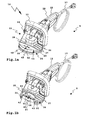
- the handle 19 is in the cross-sectional view according to FIG. 2a omitted.
- the handle 19 is expediently pivotable and fixable by means of a locking screw 20, so that the operator can adapt the hand-held machine tool 10 optimally to his ergonomic needs. The operator can grasp the hand-held power tool 10 with both hands and thus lead safely.
- the hand-held machine tool 10 is optimal:
- the tool 21 is a grinding tool for the abrasive machining of a work object 22 or a work object surface.
- the hand grinder 11 is a concrete grinder.
- the work object 22 is for example a concrete floor, a concrete wall or the like.
- the operation of the tool 21 creates a large amount of dust, which can harm the operator's health.
- the covering device 24 comprises a tool space 26 for receiving and for at least partially, in the present case completely covering the tool 21.
- the tool space 26 is provided to a large extent in a covering hood 25 of the covering device 24.
- a side edge cover 27 is provided which surrounds the tool 21 annularly in the present case.
- the side edge cover 27 is circular in correspondence with the circular outer periphery of the tool 21, here a grinding wheel.
- the housing 12 and the hood body 29 as the main component of the cover 25 expediently form a rigid structural unit. It should be noted that, of course, a flexible mounting of the cover with respect to the housing 12 is possible or an arrangement may be made, in which the hood body forms a part of the housing of a hand-held machine tool. In any case, the position of the tool 21 with respect to the tool space 26 by the rigid connection of the hood body 29 with the housing 12 is clearly defined. Nevertheless, the cover 24 has a mobility for flexible adaptation to a respective substrate to be processed.
- the side edge cover 27 is movably supported with respect to the cover hood 25, in particular with respect to the hood body 29.
- a base part 31 of the side edge cover 27 is movably supported by a guide 32 on the hood body 29.
- the guide 32 includes a guide groove 33 on a radial projection 34 of a Abdeckoberteils 35 of the cover 25.
- the Abdeckoberteil 35 includes a cover wall 36 of the tool space 26, which faces the tool top 37 of the tool 21.
- the radial projection 34 forms, as it were, a radial continuation of the cover wall 36 and is integral therewith.
- a peripheral wall 38 of the cover 25 surrounds the side edge 28 of the tool 21.
- the peripheral wall 38 projects downwardly in the direction of the tool 21 in front of the cover top 35.
- the Peripheral wall 38 forms an integral part of the Abdeckoberteils 35.
- the peripheral wall 38 forms a mechanical side protection, within which the tool 21 is arranged.
- Screws 39 which are screwed into the screw receptacles 40 of the hood body 29, hold the side edge cover 27 on the covering hood 25.
- the screw receptacles 40 are arranged, for example, between wall sections of the peripheral wall 38 or next to the peripheral wall 38.
- three screw receptacles 40 are provided at the same distance from each other.
- the screw receptacles 40 have such a distance to the side edge cover 27 that heads of the screws 39 which are screwed into the screw receptacles 40, the side edge cover 27 overhang and thus hold them to the hood body 29. Between the screw heads and the side edge cover 27 a movement play is provided.
- An abutment-spring arrangement 41 with springs 42 loads the side edge cover 27 as a whole in the direction of the workobject 22.
- the springs 42 are provided, for example, between the cover top 35, in particular its radial projection 34, and the base part 31 of the side edge cover 27.
- four springs 42 are provided, the distance of which is expediently substantially the same. In FIG. 1b the two front springs 42 are visible.
- springs 42 are expediently also provided on the side of the side edge cover facing away from the viewer.
- the side edge cover 27 has a cover 43, which by means of a pivot bearing 44 relative to the other components of the cover 24 between a cover A, in which it covers the side edge 28 of the tool 21 and an open position O pivotally mounted, in which the cover 43 has a side edge portion 45 of the tool 21 releases.
- the peripheral wall 38 has in the region of the cover 43 a cutout, through which the tool 21 protrudes forward from the tool room 26. When folded up, located in the open position O cover 43 is an optimal edge processing of the work object 22 or other surface to be machined possible. Furthermore, it is optionally provided that on a front wall 46 of the base part 31, a cutout 47 is provided, through which the tool 21 can protrude.
- the side edge cover 27 has a flexible seal 48.
- the flexible seal 48 at least in sections is formed by a rubber bead or the like.
- a brush 49 is provided, which not only optimally adapts to a substrate, but also still permeable to air, which is advantageous for effective dust removal, in particular dust extraction.
- the brush 49 extends around the entire circumference of the side edge cover 27, so that 43 are provided on both the base member 31 and the cover 43 bristles.
- the brush 49 forms a kind of brush ring, which surrounds the tool space 26 annular.
- the abutment spring assembly 41 pushes the side edge cover 27 away from the cover 25 so that the seal 48 protrudes in front of the peripheral wall 38 ( Fig. 3b . 4 ).
- the side edge cover 27 including the Bürstkranzes with the brush 49 has a low weight, so that it is easily movable with respect to the other components of the hand-held machine tool 10, in particular of the housing 12 and an optimal adaptation to a substrate to be machined succeeds. For example, if a floor is to be processed, the hand machine tool, for example, the in FIG.
- a cover element in the manner of the cover 43 is pivotally mounted on a stationary component of a hand-held machine tool.
- the cover element is movable with respect to the fixed part, in particular floating, approximately in the manner of the side edge cover 27.
- the covering element 43 is tilt-stable in the open position O or the covering position A.
- the covering element 43 tilts over a dead center position (FIG. FIG. 2a ) either in the covering position A ( FIG. 2b ) or in the open position O ( Figure 2c ).
- the operator of the hand-held machine tool 10 therefore does not have to hold the cover element 43 in the open position O or cover position A.
- the cover 43 takes the respective position automatically.
- a latch, a magnet holder or the like could be provided for holding the cover 43 in the respective position.
- a spring assembly 52 with a spring 53 holds the cover 43 in the covering position A or the open position O.
- the spring 42 is on the one hand on the base part 31 with a spring holder 54 and on the other hand on the cover 43 hinged by means of a spring holder 55.
- the spring holder 55 is provided approximately in the region of a pivot axis of the pivot bearing 44.
- the spring 53 is arranged, for example, between two pivot bearing parts of the pivot bearing 44.
- the spring holder 55 pivots, so to speak, around the spring holder 54 between the covering position A and the open position O via the dead center position FIG. 2a time.
- the cover 43 is held securely in the open position O or covering position A.
- a recess 56 is provided on the cover 43 for the spring 53.
- a dust discharge port 60 for connecting a dust-extracting device, a dust bag or the like is provided.
- the dust removal port 60 includes, for example, a connecting piece 61, which protrudes in front of an outer side of the cover 25.
- a dust removal channel 62 is formed between the tool 21 and a wall of the tool room 26, which leads to an inlet opening 63 of the dust removal terminal 60.
- a flow area of the dust discharge passage 62 increases from its start 64 to the inlet port 63.
- the dust removal channel 62 spirals around the tool spindle 15 around.
- the dust removal channel 62 is provided between the tool upper side 37 of the tool 21 and the cover wall 36 of the tool space 26 facing it.
- the cover wall 36 is expediently flat, which allows optimum flow behavior.
- the dust removal channel 62 is limited by the side wall / peripheral wall 38. However, there is a gap between the peripheral wall 38 and the side edge 28 of the tool 21 through which air can flow into the dust discharge channel 62. This inflowing air flows through the air-permeable Seal 48, in this case the brush 49, through and past the lower end face of the side wall / peripheral wall 38 into the dust discharge channel 62.
- the air passage openings 66 are provided on the tool 21, through which air can flow into the dust discharge channel 62.
- the air passage openings 66 extend from the machining side 51 of the tool 21 to the upper side 37 thereof.
- a rotational direction of the tool 21 corresponds to a flow direction of the dusty air flow 65, which increases its flow.
- the dust air flow 65 is shown as an arrow indicating the flow direction of the dust air flow 65.
- the cover wall 36 may advantageously be a plate component, for example of plastic, which is screwed to the inside to form an upper wall of the tool space 26 to the hood body.
- the cover wall 36 may also form an integral part of the hood body 29.
- the seal 48 or brush 49 is permeable to air. This makes it possible that supply air 67 can flow through the bristles of the brush 49 and past the front, free side of the peripheral wall 38 in the dust discharge channel 62, said supply air into the annular gap between the peripheral wall 38 and the side edge of the tool 21 and through the air passage openings 66 on the tool 21 flows.
- the peripheral wall 38 is advantageous in this innovative concept insofar as it laterally delimits the dust removal channel 62 and thus enables optimum flow in the direction of the inlet opening 63.
- the supply air 67 can still flow freely, so that no flow-preventing negative pressure is created.
Landscapes
- Engineering & Computer Science (AREA)
- Mechanical Engineering (AREA)
- Grinding-Machine Dressing And Accessory Apparatuses (AREA)
- Finish Polishing, Edge Sharpening, And Grinding By Specific Grinding Devices (AREA)
Applications Claiming Priority (1)
| Application Number | Priority Date | Filing Date | Title |
|---|---|---|---|
| DE102008046948A DE102008046948A1 (de) | 2008-09-12 | 2008-09-12 | Hand-Werkzeugmaschine mit einer Seitenrandabdeckung |
Publications (3)
| Publication Number | Publication Date |
|---|---|
| EP2163344A2 true EP2163344A2 (fr) | 2010-03-17 |
| EP2163344A3 EP2163344A3 (fr) | 2013-05-29 |
| EP2163344B1 EP2163344B1 (fr) | 2014-11-19 |
Family
ID=41328643
Family Applications (1)
| Application Number | Title | Priority Date | Filing Date |
|---|---|---|---|
| EP20090008603 Active EP2163344B1 (fr) | 2008-09-12 | 2009-07-01 | Machine-outil manuelle dotée d'un recouvrement de bord latéral |
Country Status (2)
| Country | Link |
|---|---|
| EP (1) | EP2163344B1 (fr) |
| DE (1) | DE102008046948A1 (fr) |
Cited By (2)
| Publication number | Priority date | Publication date | Assignee | Title |
|---|---|---|---|---|
| US9289879B2 (en) | 2013-05-02 | 2016-03-22 | Black & Decker Inc. | Hinge assembly for an angle grinder dust shroud |
| WO2019211269A1 (fr) * | 2018-05-04 | 2019-11-07 | Robert Bosch Gmbh | Aspirateur à montage facile |
Families Citing this family (3)
| Publication number | Priority date | Publication date | Assignee | Title |
|---|---|---|---|---|
| JP6531337B1 (ja) * | 2018-10-06 | 2019-06-19 | 株式会社ナカヤ | 粉塵制御機能付電動研削機 |
| DE102022134161A1 (de) | 2021-12-22 | 2023-06-22 | Festool Gmbh | Hand-Werkzeugmaschine mit in Winkelpositionen montierbarem Handgriffgehäuseteil |
| DE102021134361A1 (de) | 2021-12-22 | 2023-06-22 | Festool Gmbh | Hand-Werkzeugmaschine mit einem Stromversorgungsanschluss |
Citations (2)
| Publication number | Priority date | Publication date | Assignee | Title |
|---|---|---|---|---|
| EP0267993A1 (fr) | 1986-11-17 | 1988-05-25 | Jerome Roestenberg | Capot de protection pour meuleuse portative |
| WO1997032692A1 (fr) | 1996-03-06 | 1997-09-12 | Ulrich Wagner | Capot de protection et d'aspiration monte de façon etanche sur une rectifieuse ou ponceuse manuelle |
Family Cites Families (6)
| Publication number | Priority date | Publication date | Assignee | Title |
|---|---|---|---|---|
| US3987589A (en) * | 1972-08-02 | 1976-10-26 | Miksa Marton | Vacuum attachment for abrading machine |
| DE8815327U1 (fr) * | 1988-12-09 | 1989-03-23 | Gateway Werkzeug- Und Maschinen Vertriebs Gmbh, 4240 Emmerich, De | |
| DE4306009C2 (de) * | 1993-02-26 | 1996-05-09 | Fein C & E | Absaugeinrichtung für eine Flächenschleifmaschine |
| CH692547A5 (de) * | 1998-03-17 | 2002-07-31 | Air Tec Ag | Staubschutzhaube zu Schleiffräsen. |
| FR2882949B3 (fr) * | 2005-03-14 | 2007-02-02 | M B H Dev Sarl | Ponceuse-meuleuse aspirante ou non |
| DE102006041671B4 (de) * | 2006-09-06 | 2018-03-29 | Robert Bosch Gmbh | Schutzhaube einer Handwerkzeugmaschine |
-
2008
- 2008-09-12 DE DE102008046948A patent/DE102008046948A1/de not_active Withdrawn
-
2009
- 2009-07-01 EP EP20090008603 patent/EP2163344B1/fr active Active
Patent Citations (2)
| Publication number | Priority date | Publication date | Assignee | Title |
|---|---|---|---|---|
| EP0267993A1 (fr) | 1986-11-17 | 1988-05-25 | Jerome Roestenberg | Capot de protection pour meuleuse portative |
| WO1997032692A1 (fr) | 1996-03-06 | 1997-09-12 | Ulrich Wagner | Capot de protection et d'aspiration monte de façon etanche sur une rectifieuse ou ponceuse manuelle |
Cited By (3)
| Publication number | Priority date | Publication date | Assignee | Title |
|---|---|---|---|---|
| US9289879B2 (en) | 2013-05-02 | 2016-03-22 | Black & Decker Inc. | Hinge assembly for an angle grinder dust shroud |
| WO2019211269A1 (fr) * | 2018-05-04 | 2019-11-07 | Robert Bosch Gmbh | Aspirateur à montage facile |
| CN112074376A (zh) * | 2018-05-04 | 2020-12-11 | 罗伯特·博世有限公司 | 能简单装配的吸尘装置 |
Also Published As
| Publication number | Publication date |
|---|---|
| EP2163344B1 (fr) | 2014-11-19 |
| EP2163344A3 (fr) | 2013-05-29 |
| DE102008046948A1 (de) | 2010-03-18 |
Similar Documents
| Publication | Publication Date | Title |
|---|---|---|
| EP2163356B1 (fr) | Machine-outil manuel dotée d'un capot de recouvrement et d'un raccordement d'évacuation de poussière | |
| EP0710527B1 (fr) | Outil à main de surfaçage | |
| EP1116551B1 (fr) | Ponçeuse à guidage manuel | |
| EP2163344B1 (fr) | Machine-outil manuelle dotée d'un recouvrement de bord latéral | |
| WO2003004217A1 (fr) | Dispositif de protection pour machine-outil manuelle | |
| EP1321228B1 (fr) | Meuleuse avec capot d'aspiration | |
| EP2965865B1 (fr) | Appareil de séparation manuel | |
| DE19513279A1 (de) | Staubsammelsystem für ein maschinell angetriebenes Werkzeug | |
| EP1838496A2 (fr) | Machine-outil a main comportant un canal de guidage | |
| DE102008002548B4 (de) | Werkzeugmaschine, insbesondere Handwerkzeugmaschine | |
| EP1422032A1 (fr) | Machine-outil électrique | |
| EP2106327B1 (fr) | Machine-outil à main | |
| DE102010047529A1 (de) | Trennschleifgerät mit Staubabsaugung | |
| DE602004011029T2 (de) | Bandschleifmaschine | |
| DE3919701C2 (fr) | ||
| EP0558893A2 (fr) | Outillage à main motorisé pour rectifier, polir, dérouiller ou pour traitement de surface du genre | |
| WO2016062492A1 (fr) | Machine-outil portative pourvue d'un porte-outil sds | |
| EP0573826B1 (fr) | Ponçeuse portative motorisée à bande | |
| DE1121968B (de) | Schutz- und Absaugegehaeuse fuer Handschleif- oder dergleichen Maschinen | |
| EP3814054A1 (fr) | Bloc de meulage destiné à être utilisé manuellement ainsi que système comprenant un bloc de meulage et un article abrasif | |
| DE102014200511A1 (de) | Handwerkzeugmaschine mit einer Absaughaube | |
| DE202012008297U1 (de) | Schleifeinheit | |
| DE7718737U1 (de) | Von hand fuehrbare einrichtung zum schleifen und/oder buersten von werkstueckoberflaechen | |
| EP2123398B1 (fr) | Outil manuel destiné à l'usinage par enlèvement de matière d'une surface de pièce usinée ou de composant | |
| DE102014200401A1 (de) | Schleifwerkzeug mit einem Schleifkörper mit innenliegendem Antrieb |
Legal Events
| Date | Code | Title | Description |
|---|---|---|---|
| PUAI | Public reference made under article 153(3) epc to a published international application that has entered the european phase |
Free format text: ORIGINAL CODE: 0009012 |
|
| AK | Designated contracting states |
Kind code of ref document: A2 Designated state(s): AT BE BG CH CY CZ DE DK EE ES FI FR GB GR HR HU IE IS IT LI LT LU LV MC MK MT NL NO PL PT RO SE SI SK SM TR |
|
| AX | Request for extension of the european patent |
Extension state: AL BA RS |
|
| RAP1 | Party data changed (applicant data changed or rights of an application transferred) |
Owner name: FESTOOL GROUP GMBH & CO. KG |
|
| PUAL | Search report despatched |
Free format text: ORIGINAL CODE: 0009013 |
|
| AK | Designated contracting states |
Kind code of ref document: A3 Designated state(s): AT BE BG CH CY CZ DE DK EE ES FI FR GB GR HR HU IE IS IT LI LT LU LV MC MK MT NL NO PL PT RO SE SI SK SM TR |
|
| AX | Request for extension of the european patent |
Extension state: AL BA RS |
|
| RIC1 | Information provided on ipc code assigned before grant |
Ipc: B24B 23/02 20060101AFI20130425BHEP Ipc: B24B 55/05 20060101ALI20130425BHEP Ipc: B24B 55/10 20060101ALI20130425BHEP |
|
| 17P | Request for examination filed |
Effective date: 20131004 |
|
| RBV | Designated contracting states (corrected) |
Designated state(s): AT BE BG CH CY CZ DE DK EE ES FI FR GB GR HR HU IE IS IT LI LT LU LV MC MK MT NL NO PL PT RO SE SI SK SM TR |
|
| 17Q | First examination report despatched |
Effective date: 20131030 |
|
| GRAP | Despatch of communication of intention to grant a patent |
Free format text: ORIGINAL CODE: EPIDOSNIGR1 |
|
| INTG | Intention to grant announced |
Effective date: 20140616 |
|
| RAP1 | Party data changed (applicant data changed or rights of an application transferred) |
Owner name: FESTOOL GMBH |
|
| GRAS | Grant fee paid |
Free format text: ORIGINAL CODE: EPIDOSNIGR3 |
|
| GRAA | (expected) grant |
Free format text: ORIGINAL CODE: 0009210 |
|
| AK | Designated contracting states |
Kind code of ref document: B1 Designated state(s): AT BE BG CH CY CZ DE DK EE ES FI FR GB GR HR HU IE IS IT LI LT LU LV MC MK MT NL NO PL PT RO SE SI SK SM TR |
|
| REG | Reference to a national code |
Ref country code: GB Ref legal event code: FG4D Free format text: NOT ENGLISH |
|
| REG | Reference to a national code |
Ref country code: CH Ref legal event code: EP |
|
| REG | Reference to a national code |
Ref country code: AT Ref legal event code: REF Ref document number: 696709 Country of ref document: AT Kind code of ref document: T Effective date: 20141215 |
|
| REG | Reference to a national code |
Ref country code: IE Ref legal event code: FG4D Free format text: LANGUAGE OF EP DOCUMENT: GERMAN |
|
| REG | Reference to a national code |
Ref country code: DE Ref legal event code: R096 Ref document number: 502009010231 Country of ref document: DE Effective date: 20141231 |
|
| REG | Reference to a national code |
Ref country code: NL Ref legal event code: VDEP Effective date: 20141119 |
|
| REG | Reference to a national code |
Ref country code: LT Ref legal event code: MG4D |
|
| PG25 | Lapsed in a contracting state [announced via postgrant information from national office to epo] |
Ref country code: IS Free format text: LAPSE BECAUSE OF FAILURE TO SUBMIT A TRANSLATION OF THE DESCRIPTION OR TO PAY THE FEE WITHIN THE PRESCRIBED TIME-LIMIT Effective date: 20150319 Ref country code: FI Free format text: LAPSE BECAUSE OF FAILURE TO SUBMIT A TRANSLATION OF THE DESCRIPTION OR TO PAY THE FEE WITHIN THE PRESCRIBED TIME-LIMIT Effective date: 20141119 Ref country code: NL Free format text: LAPSE BECAUSE OF FAILURE TO SUBMIT A TRANSLATION OF THE DESCRIPTION OR TO PAY THE FEE WITHIN THE PRESCRIBED TIME-LIMIT Effective date: 20141119 Ref country code: LT Free format text: LAPSE BECAUSE OF FAILURE TO SUBMIT A TRANSLATION OF THE DESCRIPTION OR TO PAY THE FEE WITHIN THE PRESCRIBED TIME-LIMIT Effective date: 20141119 Ref country code: PT Free format text: LAPSE BECAUSE OF FAILURE TO SUBMIT A TRANSLATION OF THE DESCRIPTION OR TO PAY THE FEE WITHIN THE PRESCRIBED TIME-LIMIT Effective date: 20150319 Ref country code: ES Free format text: LAPSE BECAUSE OF FAILURE TO SUBMIT A TRANSLATION OF THE DESCRIPTION OR TO PAY THE FEE WITHIN THE PRESCRIBED TIME-LIMIT Effective date: 20141119 Ref country code: NO Free format text: LAPSE BECAUSE OF FAILURE TO SUBMIT A TRANSLATION OF THE DESCRIPTION OR TO PAY THE FEE WITHIN THE PRESCRIBED TIME-LIMIT Effective date: 20150219 |
|
| PG25 | Lapsed in a contracting state [announced via postgrant information from national office to epo] |
Ref country code: GR Free format text: LAPSE BECAUSE OF FAILURE TO SUBMIT A TRANSLATION OF THE DESCRIPTION OR TO PAY THE FEE WITHIN THE PRESCRIBED TIME-LIMIT Effective date: 20150220 Ref country code: CY Free format text: LAPSE BECAUSE OF FAILURE TO SUBMIT A TRANSLATION OF THE DESCRIPTION OR TO PAY THE FEE WITHIN THE PRESCRIBED TIME-LIMIT Effective date: 20141119 Ref country code: HR Free format text: LAPSE BECAUSE OF FAILURE TO SUBMIT A TRANSLATION OF THE DESCRIPTION OR TO PAY THE FEE WITHIN THE PRESCRIBED TIME-LIMIT Effective date: 20141119 Ref country code: LV Free format text: LAPSE BECAUSE OF FAILURE TO SUBMIT A TRANSLATION OF THE DESCRIPTION OR TO PAY THE FEE WITHIN THE PRESCRIBED TIME-LIMIT Effective date: 20141119 Ref country code: PL Free format text: LAPSE BECAUSE OF FAILURE TO SUBMIT A TRANSLATION OF THE DESCRIPTION OR TO PAY THE FEE WITHIN THE PRESCRIBED TIME-LIMIT Effective date: 20141119 Ref country code: SE Free format text: LAPSE BECAUSE OF FAILURE TO SUBMIT A TRANSLATION OF THE DESCRIPTION OR TO PAY THE FEE WITHIN THE PRESCRIBED TIME-LIMIT Effective date: 20141119 |
|
| PG25 | Lapsed in a contracting state [announced via postgrant information from national office to epo] |
Ref country code: RO Free format text: LAPSE BECAUSE OF FAILURE TO SUBMIT A TRANSLATION OF THE DESCRIPTION OR TO PAY THE FEE WITHIN THE PRESCRIBED TIME-LIMIT Effective date: 20141119 Ref country code: SK Free format text: LAPSE BECAUSE OF FAILURE TO SUBMIT A TRANSLATION OF THE DESCRIPTION OR TO PAY THE FEE WITHIN THE PRESCRIBED TIME-LIMIT Effective date: 20141119 Ref country code: DK Free format text: LAPSE BECAUSE OF FAILURE TO SUBMIT A TRANSLATION OF THE DESCRIPTION OR TO PAY THE FEE WITHIN THE PRESCRIBED TIME-LIMIT Effective date: 20141119 Ref country code: CZ Free format text: LAPSE BECAUSE OF FAILURE TO SUBMIT A TRANSLATION OF THE DESCRIPTION OR TO PAY THE FEE WITHIN THE PRESCRIBED TIME-LIMIT Effective date: 20141119 Ref country code: EE Free format text: LAPSE BECAUSE OF FAILURE TO SUBMIT A TRANSLATION OF THE DESCRIPTION OR TO PAY THE FEE WITHIN THE PRESCRIBED TIME-LIMIT Effective date: 20141119 |
|
| REG | Reference to a national code |
Ref country code: DE Ref legal event code: R097 Ref document number: 502009010231 Country of ref document: DE |
|
| PLBE | No opposition filed within time limit |
Free format text: ORIGINAL CODE: 0009261 |
|
| STAA | Information on the status of an ep patent application or granted ep patent |
Free format text: STATUS: NO OPPOSITION FILED WITHIN TIME LIMIT |
|
| 26N | No opposition filed |
Effective date: 20150820 |
|
| PG25 | Lapsed in a contracting state [announced via postgrant information from national office to epo] |
Ref country code: IT Free format text: LAPSE BECAUSE OF FAILURE TO SUBMIT A TRANSLATION OF THE DESCRIPTION OR TO PAY THE FEE WITHIN THE PRESCRIBED TIME-LIMIT Effective date: 20141119 |
|
| PG25 | Lapsed in a contracting state [announced via postgrant information from national office to epo] |
Ref country code: SI Free format text: LAPSE BECAUSE OF FAILURE TO SUBMIT A TRANSLATION OF THE DESCRIPTION OR TO PAY THE FEE WITHIN THE PRESCRIBED TIME-LIMIT Effective date: 20141119 Ref country code: MC Free format text: LAPSE BECAUSE OF FAILURE TO SUBMIT A TRANSLATION OF THE DESCRIPTION OR TO PAY THE FEE WITHIN THE PRESCRIBED TIME-LIMIT Effective date: 20141119 |
|
| REG | Reference to a national code |
Ref country code: CH Ref legal event code: PL |
|
| PG25 | Lapsed in a contracting state [announced via postgrant information from national office to epo] |
Ref country code: LU Free format text: LAPSE BECAUSE OF FAILURE TO SUBMIT A TRANSLATION OF THE DESCRIPTION OR TO PAY THE FEE WITHIN THE PRESCRIBED TIME-LIMIT Effective date: 20150701 |
|
| REG | Reference to a national code |
Ref country code: IE Ref legal event code: MM4A |
|
| PG25 | Lapsed in a contracting state [announced via postgrant information from national office to epo] |
Ref country code: CH Free format text: LAPSE BECAUSE OF NON-PAYMENT OF DUE FEES Effective date: 20150731 Ref country code: LI Free format text: LAPSE BECAUSE OF NON-PAYMENT OF DUE FEES Effective date: 20150731 |
|
| REG | Reference to a national code |
Ref country code: FR Ref legal event code: PLFP Year of fee payment: 8 |
|
| PG25 | Lapsed in a contracting state [announced via postgrant information from national office to epo] |
Ref country code: IE Free format text: LAPSE BECAUSE OF NON-PAYMENT OF DUE FEES Effective date: 20150701 |
|
| REG | Reference to a national code |
Ref country code: AT Ref legal event code: MM01 Ref document number: 696709 Country of ref document: AT Kind code of ref document: T Effective date: 20150701 |
|
| PG25 | Lapsed in a contracting state [announced via postgrant information from national office to epo] |
Ref country code: AT Free format text: LAPSE BECAUSE OF NON-PAYMENT OF DUE FEES Effective date: 20150701 |
|
| PG25 | Lapsed in a contracting state [announced via postgrant information from national office to epo] |
Ref country code: MT Free format text: LAPSE BECAUSE OF FAILURE TO SUBMIT A TRANSLATION OF THE DESCRIPTION OR TO PAY THE FEE WITHIN THE PRESCRIBED TIME-LIMIT Effective date: 20141119 |
|
| REG | Reference to a national code |
Ref country code: FR Ref legal event code: PLFP Year of fee payment: 9 |
|
| PG25 | Lapsed in a contracting state [announced via postgrant information from national office to epo] |
Ref country code: HU Free format text: LAPSE BECAUSE OF FAILURE TO SUBMIT A TRANSLATION OF THE DESCRIPTION OR TO PAY THE FEE WITHIN THE PRESCRIBED TIME-LIMIT; INVALID AB INITIO Effective date: 20090701 Ref country code: SM Free format text: LAPSE BECAUSE OF FAILURE TO SUBMIT A TRANSLATION OF THE DESCRIPTION OR TO PAY THE FEE WITHIN THE PRESCRIBED TIME-LIMIT Effective date: 20141119 Ref country code: BG Free format text: LAPSE BECAUSE OF FAILURE TO SUBMIT A TRANSLATION OF THE DESCRIPTION OR TO PAY THE FEE WITHIN THE PRESCRIBED TIME-LIMIT Effective date: 20141119 |
|
| PG25 | Lapsed in a contracting state [announced via postgrant information from national office to epo] |
Ref country code: BE Free format text: LAPSE BECAUSE OF NON-PAYMENT OF DUE FEES Effective date: 20150731 |
|
| PG25 | Lapsed in a contracting state [announced via postgrant information from national office to epo] |
Ref country code: TR Free format text: LAPSE BECAUSE OF FAILURE TO SUBMIT A TRANSLATION OF THE DESCRIPTION OR TO PAY THE FEE WITHIN THE PRESCRIBED TIME-LIMIT Effective date: 20141119 |
|
| REG | Reference to a national code |
Ref country code: FR Ref legal event code: PLFP Year of fee payment: 10 |
|
| PG25 | Lapsed in a contracting state [announced via postgrant information from national office to epo] |
Ref country code: MK Free format text: LAPSE BECAUSE OF FAILURE TO SUBMIT A TRANSLATION OF THE DESCRIPTION OR TO PAY THE FEE WITHIN THE PRESCRIBED TIME-LIMIT Effective date: 20141119 |
|
| P01 | Opt-out of the competence of the unified patent court (upc) registered |
Effective date: 20230517 |
|
| PGFP | Annual fee paid to national office [announced via postgrant information from national office to epo] |
Ref country code: FR Payment date: 20230601 Year of fee payment: 15 |
|
| PGFP | Annual fee paid to national office [announced via postgrant information from national office to epo] |
Ref country code: GB Payment date: 20230601 Year of fee payment: 15 |
|
| PGFP | Annual fee paid to national office [announced via postgrant information from national office to epo] |
Ref country code: DE Payment date: 20230614 Year of fee payment: 15 |