EP0558893A2 - Outillage à main motorisé pour rectifier, polir, dérouiller ou pour traitement de surface du genre - Google Patents
Outillage à main motorisé pour rectifier, polir, dérouiller ou pour traitement de surface du genre Download PDFInfo
- Publication number
- EP0558893A2 EP0558893A2 EP93100473A EP93100473A EP0558893A2 EP 0558893 A2 EP0558893 A2 EP 0558893A2 EP 93100473 A EP93100473 A EP 93100473A EP 93100473 A EP93100473 A EP 93100473A EP 0558893 A2 EP0558893 A2 EP 0558893A2
- Authority
- EP
- European Patent Office
- Prior art keywords
- handle
- motor housing
- motor
- cover part
- guide
- Prior art date
- Legal status (The legal status is an assumption and is not a legal conclusion. Google has not performed a legal analysis and makes no representation as to the accuracy of the status listed.)
- Granted
Links
Images

Classifications
-
- B—PERFORMING OPERATIONS; TRANSPORTING
- B24—GRINDING; POLISHING
- B24B—MACHINES, DEVICES, OR PROCESSES FOR GRINDING OR POLISHING; DRESSING OR CONDITIONING OF ABRADING SURFACES; FEEDING OF GRINDING, POLISHING, OR LAPPING AGENTS
- B24B55/00—Safety devices for grinding or polishing machines; Accessories fitted to grinding or polishing machines for keeping tools or parts of the machine in good working condition
- B24B55/06—Dust extraction equipment on grinding or polishing machines
- B24B55/10—Dust extraction equipment on grinding or polishing machines specially designed for portable grinding machines, e.g. hand-guided
- B24B55/102—Dust extraction equipment on grinding or polishing machines specially designed for portable grinding machines, e.g. hand-guided with rotating tools
-
- B—PERFORMING OPERATIONS; TRANSPORTING
- B24—GRINDING; POLISHING
- B24B—MACHINES, DEVICES, OR PROCESSES FOR GRINDING OR POLISHING; DRESSING OR CONDITIONING OF ABRADING SURFACES; FEEDING OF GRINDING, POLISHING, OR LAPPING AGENTS
- B24B23/00—Portable grinding machines, e.g. hand-guided; Accessories therefor
- B24B23/005—Auxiliary devices used in connection with portable grinding machines, e.g. holders
-
- B—PERFORMING OPERATIONS; TRANSPORTING
- B25—HAND TOOLS; PORTABLE POWER-DRIVEN TOOLS; MANIPULATORS
- B25F—COMBINATION OR MULTI-PURPOSE TOOLS NOT OTHERWISE PROVIDED FOR; DETAILS OR COMPONENTS OF PORTABLE POWER-DRIVEN TOOLS NOT PARTICULARLY RELATED TO THE OPERATIONS PERFORMED AND NOT OTHERWISE PROVIDED FOR
- B25F5/00—Details or components of portable power-driven tools not particularly related to the operations performed and not otherwise provided for
- B25F5/02—Construction of casings, bodies or handles
- B25F5/025—Construction of casings, bodies or handles with torque reaction bars for rotary tools
- B25F5/026—Construction of casings, bodies or handles with torque reaction bars for rotary tools in the form of an auxiliary handle
Definitions
- the invention relates to a hand-held, motor-driven device for grinding, polishing, rust removal or the like machining of surfaces, with a drive motor arranged in a motor housing, which has a rotating motor shaft during operation, which drives a tool holder for a disk-shaped machining tool, in particular
- the axis of rotation preferably coincides with the motor shaft, and with a handle that extends at an angle to the motor shaft and projects laterally from the motor housing.
- a device of this type can be found, for example, in German Utility Model 82 28 297. It has an essentially cylindrical motor housing, which receives the drive motor, to the motor shaft of which a respective machining tool is connected.
- a rod-shaped handle is used to handle the device, which is in particular integrally attached to the motor housing and projects laterally from it.
- the second handle designed as a guide handle, allows the device to be guided much more safely because it can be held with both hands. Tilting of the machining tool in relation to a surface to be machined can therefore be largely excluded. However, should a force act on the device that it intends to throw off the track, such conditions can be counteracted optimally by holding the handle. Even hard-to-reach places on workpieces, e.g. Narrow folds, misshapen bumps, corners and edges can now be processed much more precisely.
- the possibility of adjusting the guide handle allows the respective user to determine the relative position between the two handles in a way that appears optimal to him.
- the handle can be easily moved to a safe circumferential position if it is suitable for certain jobs, e.g. for grinding in corner areas, should be in an unfavorable circumferential position.
- the device according to the invention is extremely light and can weigh less than 0.5 kg. In addition, it is relatively quiet, inexpensive and extremely compact. It can be easily used for electrical mains operation or for mainsless battery or. Design battery operation.
- the guide handle is expediently arranged on the motor housing in an infinitely variable manner and can be fixed in any circumferential position on the motor housing.
- the adjustment range preferably extends over 360 degrees.
- the guide handle is arranged in the direction of the axis of rotation at least at approximately the same height as the handle on the motor housing, the handle having a receiving opening located in the adjustment path of the guide handle, in which the guide handle at least partially taking a rest position can be arranged sunk. If the handle is not required, it can be moved to a non-obstructing position without having to be removed.
- the receiving opening is preferably designed such that it traverses the handle in the circumferential direction with respect to the axis of rotation, so that the guide handle can be moved through as part of its positioning. This ensures short adjustment paths.
- the guide handle itself is preferably designed as a handle for its adjustment and releasable fixing relative to the motor housing. This saves additional fasteners. It expediently forms a rotary member to be rotated for loosening or fixing, the axis of rotation preferably coinciding with the direction in which it protrudes from the motor housing.
- the guide handle is arranged on a clamping band surrounding the motor housing in the circumferential direction with respect to the axis of rotation.
- this clamping band can expediently be braced or released from the motor housing by acting on the handle.
- the device can easily be placed on and / or guided along any reference surface during a machining process. This increases the precision of the machining processes even more in special cases.
- the device can be connected to a suction device for dust, chips or similar contaminants, hereinafter referred to as a dust suction device.
- a dust suction device This effectively protects the work area and the surrounding area from dirt.
- the means for dust extraction are processing cumbersome and can contribute to an increase in weight of the device. So that these disadvantages do not occur, the device can have a cover part which can be detachably fixed in a cover position with partial covering of the gripping surface on the handle, forming a suction channel of a dust extraction device opening into the working area of the held processing tool and at the same time with its outer surface as a gripping surface section takes the place of the covered handle section.
- the handle When the cover is removed, the handle is in its original shape. At times when dust extraction is desired, only the cover part needs to be attached, so that there is a suction channel to which, for example, a suction unit can be connected. Since the outer surface of the cover part takes over the gripping surface function, the handling of the device does not change compared to the removed cover part. This is advantageous for the user.
- the removable cover part can be realized with practically all motor-driven processing devices or power tools. However, it is particularly advantageous in connection with a device of the type in question here, in which the weight saving plays a significant role.
- the device shown in the drawing is designed as a hand-held device and is used for grinding, polishing, brushing, rust removal or other comparable work on any object surface.
- the type of machining mainly depends on the machining tool operated with the device. You could also call the device a hand tool.
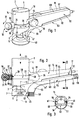
- the device has a motor housing 1 with a substantially circular cylindrical shape on the outside.
- the two end faces represent the top 2 and the bottom 3 of the motor housing 1.
- an electric drive motor 4 which is only indicated by dashed lines and which has a driven motor shaft 5 which projects from the motor housing 1 on the underside 3.
- a tool holder 6 At the free end of the motor shaft 5 there is a tool holder 6, indicated only by dashed lines, which in the exemplary embodiment is formed by a threaded section which cooperates with a clamping nut.
- a disk-shaped machining tool 7 is detachably and coaxially fixed to it.
- the exemplary embodiment is a grinding plate covered with an abrasive coating 8.
- the machining tool 7 Since the machining tool 7 is fixed directly to the motor shaft 5, a compact construction results, with the drive motor 4 being located centrally above the machining tool 7. It is preferably a gearless arrangement, so that the engine speed coincides with the speed of the machining tool 7 and there is no need for weight-increasing gear means which are noisy during operation, such as meshing gears. While maintaining the advantages, the machining tool 7 could also be seated on a linear extension of the motor shaft 5. In any case, an arrangement is preferred in which the axis of rotation 9 of the machining tool 7 and the tool holder 6 coincide with the motor shaft 5, that is to say the axis of rotation 13 thereof.
- a handle 15 is arranged laterally, in the region of the peripheral surface 14 of the motor housing 1 formed by the cylindrical jacket. It is firmly and permanently connected to the motor housing 1, in particular in that it is formed in one piece with the motor housing 1. In the exemplary embodiment, it has an essentially rod-shaped shape and extends at an angle to the motor shaft 5, so that it projects laterally from the motor housing 1. 4, the longitudinal axis 16 of the handle 15 expediently runs radially with respect to the circumferential surface 14. In the side view according to FIG. 2, the longitudinal axis 16 can run at right angles to the axis of rotation 13, but is preferably, as shown, slightly inclined, so that the handle 15 rises slightly upwards towards its free end 17. In the exemplary embodiment, the handle 15 starts in the section of the peripheral surface 14 that follows the underside 3. Since its width measured in the height direction is less than the height of the motor housing 1, this protrudes with an upper cylindrical end section 18 over the handle 15.
- the diameter of the machining tool 7 expediently corresponds at least substantially to the diameter of the motor housing 1.
- the device also has a second handle, which is referred to as a guide handle 19, since it is gripped by the user mainly for guiding the device.
- the rigid handle 15 serves rather to hold the device in general and to transmit the contact pressure to a surface on which the machining tool 7 is applied.
- the guide handle 19 is also arranged laterally, in the region of the peripheral surface 14, on the motor housing 1 and projects radially from it, in particular radially to the axis of rotation 13. Its longitudinal extent, measured in the direction of the free end, is less than that of the handle 15, that is, it projects less than this from the motor housing 1.
- the guide handle 19 has a substantially button-like shape.
- a great advantage of the guide handle 19 is that it is adjustable relative to the motor housing 1 in the circumferential direction with respect to the axis of rotation 9.
- the direction of adjustment is indicated in FIGS. 1 and 4 by the double arrow 20.
- the guide handle 19 can be releasably fixed with respect to the motor housing 1, forming a practically rigid handle in the fixed state.
- the guide handle 19 assumes a circumferential position 21 diametrically opposite the handle 15. It stands in the opposite direction to the handle 15 from the motor housing 1.
- the separate guide handle 19 is held on the motor housing 1 by means of a clamping band 22.
- This is placed around the motor housing 1 in a coaxial arrangement, wherein it extends in the circumferential direction with respect to the axis of rotation 9 and thus in the direction of adjustment 20 and bears against the circumferential surface 14 .
- the clamping band 22 can either be tensioned such that it is immovably fixed relative to the motor housing 1, or it can be released so that it together with the guide handle 19 in the direction of adjustment 20 up to the desired circumferential position 21 relative to the motor housing 1 is rotatable.
- the advantage here is that the guide handle 19 can be adjusted continuously and can be locked in any possible circumferential position.
- FIG. 4 only a few of the possible circumferential positions are selected as examples.
- a circumferential surface 14 can be shown, at least partially along the circumferential surface 14 extending recess into which the clamping band 22 is immersed with at least part of its thickness.
- the flanks of the depression here form stops which prevent the clamping band 22 from moving in the height direction 23 without interfering with the movement in the adjustment direction 20.
- the guide handle 19 comprises a threaded part 27, which extends radially outwards from the already mentioned outer surface 28 of the clamping band 22.
- it is formed by the shank of a screw 29 which is fixedly placed on the outer surface 28 with the head surface 30 opposite the shank.
- a welded or adhesive connection can be provided for the fixed connection.
- a screw part 31 is placed on the threaded part 27 and can be screwed back and forth on the threaded part 27 by turning it according to the double arrow 32 shown in FIG. 1.
- it has the shape of a ball.
- a pressing element 33 which is supported on the one hand on the screw part 31 and on the other hand on the peripheral surface 14 of the motor housing 1.
- it is sleeve-shaped and axially adjustably attached to the screw 29.
- the pressing surface 34 cooperating with the screw part 31 is spherically complementary to the spherical shape in the exemplary embodiment, so that the pressing force is optimally transmitted.
- the pressing element 33 is provided with a recess 35 which is continuous in the longitudinal direction of the band and into which the clamping band 22 can be immersed, the parts of the pressing element 33 lying next to the recess 35 forming pressing parts 36 which support against the peripheral surface 14.
- the through opening 37 of the pressing element 33 which allows it to be plugged onto the screw part 31, is widened in the area adjacent to the recess 35 in such a way that the screw head is also received.
- the guide handle 19 of the embodiment is designed as a rotary handle.
- the pressing element 33 with its pressing parts 36 is pressed against the circumferential surface 14, as a result of this support the clamping band 22 connected to the threaded part 27 is pulled radially outward in the connection area with the threaded part 27.
- the clamping band 22 is tensioned against the motor housing 1, particularly in the areas diametrically opposite the guide handle 19.
- the adjustment range of the guide handle 19 extends over 360 degrees. It can therefore be arranged anywhere along the peripheral surface 14. This adjustment possibility could indeed be realized by attaching the clamping band 22 to the upwardly projecting end section 18. In the embodiment, however, a more advantageous variant is realized.
- the guide handle 19, viewed in the height direction 23, is arranged at the same height as the attachment point of the handle 15. As can be clearly seen from FIG. 2, the guide handle 19 assumes a position in the region of the middle of the height of the handle 15.
- the width of the guide handle 19 measured in the height direction 23 is less than the correspondingly measured width of the section 38 of the handle 15 directly adjoining the motor housing 1.
- This section 38 is provided with a receiving opening 39 which crosses the handle 15 in the circumferential direction with respect to the axis of rotation 9. Their cross-sectional contour is selected so that the handle 19 fits through. It adjoins the peripheral surface 14 of the motor housing 1, that is, one in the height region of the receiving opening 39 has circular cylindrical peripheral portion 40.
- the clamping band 20 is wrapped around this circumferential section 40 and thus runs through the receiving opening 39.
- Above and below the receiving opening 39 there are web-like grip parts 44, 44 ', via which the handle 15 is firmly connected to the motor housing 1.
- the guide handle 19 comes to lie very close to the machining tool 7 and thus to the working area 45 of the device. This allows the device to be guided precisely during a machining operation. At the same time, there is the possibility of positioning the guide handle 19 freely at any point on the circumference of the motor housing 1 by the handle 15.
- the actual task of the receiving opening 39 is, however, to receive the guide handle 19 in a rest position if it is not required or is a hindrance due to special circumstances in the context of the current processing.
- This rest position is shown in FIG. 4 at 21 ′′.
- the guide handle 19 comes to rest completely sunk in the handle 15, so that the device has a shape without complex removal of the guide handle 19, which corresponds to that of a handle-less device.
- the guide handle 19 and in particular its screw part 31 is easily accessible in order to be in the rest position 21 '' to be able to clamp against the motor housing 1 and to loosen it again later. It may also be expedient to match the width of the guide handle 19 to the width of the handle 15 in such a way that the screw part 31 in the rest position 21 ′′ slightly projects beyond the lateral outer surfaces 46 of the handle 15 on both sides and is therefore easy to grasp (not shown). .
- the receiving opening 39 is closed all the way apart from the lateral openings, in an exemplary embodiment not shown it is open at one point on its circumference, in particular towards the top 2. This allows an even better handling of the handle 19 in the rest position 21 ''.
- the device formed is furthermore provided with a contact surface 47 with which it can be applied and / or moved along a reference surface formed, for example, by the object to be processed during a machining process.
- a contact surface 47 with which it can be applied and / or moved along a reference surface formed, for example, by the object to be processed during a machining process.
- two such contact surfaces 47 are provided, which are arranged in mirror image with respect to a vertical plane containing the axis of rotation 9 and the longitudinal axis 16.
- the respective contact surface 47 is located in the area of the underside 3 of the motor housing 1, and as shown it can protrude in the direction of the machining tool 7 via the motor housing 1.
- the contact surface 47 also expediently protrudes radially beyond the peripheral edge 49 of the respective machining tool 7, as can be seen above all from FIG.
- the respective contact surface 47 is preferably designed as a flat surface which runs in a tangential plane applied to the machining tool 7 or the motor housing 1 or in a plane parallel thereto.
- the respective contact surface 47 begins at a point 50 of the circumferential surface 14 on both sides of the vertical plane mentioned and extends from there in the direction of the handle 15, its distance from the longitudinal axis 16 increasing with increasing distance from the circumferential surface 14.
- the contact surfaces 47 are expediently formed integrally on the motor housing 1 and / or the handle 15.
- the device shown is preferably also designed for dust extraction. It is possible to connect a suction unit (not shown in more detail) and thereby remove abrasion occurring in the work area 45, hereinafter referred to as dust, from the work area 45.
- a suction unit not shown in more detail
- dust abrasion occurring in the work area 45
- such means are a hindrance or lead to a disadvantageous increase in weight in fine machining operations, so that it is advantageous if the agents can be removed when not in use.
- a cover part 51 is provided as the means for dust extraction in the device shown. It can be detachably attached to the handle 15 in a covering position that is clearly visible in FIGS. 2 and 3.
- the gripping surface 52 of the handle 15 that is to say that surface which extends over the circumference of the handle 15 and which the user normally grips with one hand when handling the device, is partially covered in the covering position by the covering part 51. In the exemplary embodiment, this is essentially the downward-facing part 53 of the gripping surface 52, since the cover part 51 sits in the cover position on the underside of the handle 15 facing the work area.
- the design of the cover part 51 is matched to the shape of the handle 15 in such a way that these two parts delimit between them a suction channel 54 which opens into the working area 45 and which belongs to a dust suction device.
- the cover part 51 has a groove-like cross-sectional contour which can be seen in FIG. 3, the suction space being delimited on the one hand by the concavely curved inner surface 55 of the cover part 51 and on the other hand directly by the covered gripping surface part 53.
- the cover part 51 is designed such that the suction channel 54 essentially follows the longitudinal course of the handle 15 and, when approaching the motor housing 1, runs downward in an arcuate section 56 to the working area 45.
- the width of the suction channel 54 corresponds essentially to the width of the handle 15. Only in the area of the arch section 56 does the suction channel 54 widen and open into a suction opening 57 which extends in an arc along a peripheral section of the machining tool 7.
- the cover part 51 can be provided with a sealing trim 58 which, in the exemplary embodiment, is formed by a bristle partial ring.
- the cover part 51 can have a connecting section 59, via which, for example, a flexible suction line leading to a suction unit can be connected.
- the cover part 51 expediently has a rounded outer surface 60. In the cover position, this takes the place of the covered gripping surface part 53, so that it fulfills the gripping surface function and the cover part 51 practically belongs to the handle 15.
- the device can always be gripped comfortably.
- the detachable mounting of the cover part 51 on the handle 15 takes place in the exemplary embodiment by means of a plug connection device 61.
- a longitudinal groove 62 is provided on the handle 15 in the region of the two lateral outer surfaces 46, which run parallel to the longitudinal axis 16.
- the cover part 51 engages in the longitudinal groove 62 with holding projections 64 which are formed in the region of the longitudinal opening 63 at the edge regions of the cover part 51. If the longitudinal grooves 62 are open towards the free end 17, the holding projections 64 can be inserted from there without any problems.
- the slot-like longitudinal opening 63 of the cover part 51 is expediently covered by a guide surface 65 on the device.
- An end section 66 of the cover part 51 which protrudes beyond the free end 17 as in the exemplary embodiment, is expediently designed to be closed in a tubular manner over the circumference, so that there is no pressure drop.
- the cover part 51 can in principle be designed as a tubular part over the entire length, with any holding projections 64 present in the area the outer surface can be molded. It is also possible to make the longitudinal opening 63 closed on both narrow sides, so that the cover part 51 has a tubular shape in the region of both end sections.
- the holding projections 64 in this case extend, for example, only over the length of the longitudinal opening 63.
- the abovementioned contact surfaces 47 can also be provided at least partially on the cover part 51. This allows for easy removal from the device should they prove to be a hindrance.
- cover part described can also be used advantageously in connection with other hand power tools, regardless of their other design. Even with machines with a non-rotating processing tool, for example with jigsaws, this measure, which is advantageous for dust extraction, can be implemented without further ado.
- the motor housing 1 and the handle 15 advantageously form a device housing which is divided in the middle along the above-mentioned vertical plane (at 67), the two housing halves 68 being detachable from one another for repair and assembly purposes.
Landscapes
- Engineering & Computer Science (AREA)
- Mechanical Engineering (AREA)
- Finish Polishing, Edge Sharpening, And Grinding By Specific Grinding Devices (AREA)
Applications Claiming Priority (2)
| Application Number | Priority Date | Filing Date | Title |
|---|---|---|---|
| DE4203171 | 1992-02-05 | ||
| DE4203171A DE4203171C1 (fr) | 1992-02-05 | 1992-02-05 |
Publications (3)
| Publication Number | Publication Date |
|---|---|
| EP0558893A2 true EP0558893A2 (fr) | 1993-09-08 |
| EP0558893A3 EP0558893A3 (en) | 1993-12-08 |
| EP0558893B1 EP0558893B1 (fr) | 1996-05-01 |
Family
ID=6450952
Family Applications (1)
| Application Number | Title | Priority Date | Filing Date |
|---|---|---|---|
| EP93100473A Expired - Lifetime EP0558893B1 (fr) | 1992-02-05 | 1993-01-14 | Outillage à main motorisé pour rectifier, polir, dérouiller ou pour traitement de surface du genre |
Country Status (2)
| Country | Link |
|---|---|
| EP (1) | EP0558893B1 (fr) |
| DE (3) | DE4238245C3 (fr) |
Families Citing this family (7)
| Publication number | Priority date | Publication date | Assignee | Title |
|---|---|---|---|---|
| FR2734745B1 (fr) * | 1995-05-29 | 1997-07-04 | Peugeot | Dispositif d'aspiration des matieres detachees en cours d'usinage, adaptable sur une machine-outil. |
| DE19606535C2 (de) * | 1996-02-22 | 1999-01-07 | Metabowerke Kg | Motorbetriebenes Handwerkzeug mit abnehmbarem Handgriff |
| DE19623152C1 (de) * | 1996-06-10 | 1997-08-28 | Alois Steffgen | Externes Absaugsystem eines Abrieb erzeugenden Werkzeugs |
| DE19854468A1 (de) | 1998-11-25 | 2000-06-08 | Flex Elektrowerkzeuge Gmbh | Handwerkzeugmaschine |
| US6260591B1 (en) | 1999-08-11 | 2001-07-17 | Black & Decker Inc. | Biscuit joiner |
| JP5297392B2 (ja) * | 2009-07-06 | 2013-09-25 | 株式会社マキタ | サンダー |
| TWM635552U (zh) * | 2022-01-11 | 2022-12-21 | 鑽全實業股份有限公司 | 研磨工具及其機殼 |
Citations (5)
| Publication number | Priority date | Publication date | Assignee | Title |
|---|---|---|---|---|
| JPS55112759A (en) * | 1979-02-19 | 1980-08-30 | Shibaura Eng Works Co Ltd | Disk grinder |
| DE8228297U1 (de) * | 1982-10-08 | 1983-01-20 | Festo-Maschinenfabrik Gottlieb Stoll, 7300 Esslingen | Als handgeraet ausgebildetes geraet zum schleifen, polieren, entrosten od. dgl. bearbeiten von oberflaechen |
| EP0191509A1 (fr) * | 1985-01-18 | 1986-08-20 | Guido Valentini | Fraiseuse et/ou rogneuse électrique portative munie d'une aspiration des copeaux et de la poussière produits |
| EP0227644A2 (fr) * | 1985-01-18 | 1987-07-01 | Guido Valentini | Outil électrique portatif pour l'usinage de surfaces de matériaux avec conduit d'aspiration de poussière prévu dans la poignée de maintien |
| EP0252552A1 (fr) * | 1986-07-02 | 1988-01-13 | Guido Valentini | Outil électrique portatif équipé d'un moteur et de moyens d'aspiration des poussières incorporés dans la poignée |
Family Cites Families (4)
| Publication number | Priority date | Publication date | Assignee | Title |
|---|---|---|---|---|
| DE2559132C2 (de) * | 1975-12-30 | 1983-11-03 | Kurt Richard 7000 Stuttgart Ranger | Griffanordnung für tragbare kraftbetriebene Werkzeuge |
| DE3038489C2 (de) * | 1980-10-11 | 1984-01-26 | Festo-Maschinenfabrik Gottlieb Stoll, 7300 Esslingen | Handwerkzeugmaschine mit einem rotierend angetriebenen Werkzeug |
| SE446698B (sv) * | 1983-09-16 | 1986-10-06 | Atlas Copco Ab | "handhallet maskinverktyg innefattande ett motorhus och tva pa huset monterade handtag av vilka atminstone det ena er instellbart anordnat" |
| DE3724747A1 (de) * | 1987-07-25 | 1989-02-02 | Fein C & E | Schleifgeraet mit staubabsaugeinrichtung |
-
1992
- 1992-02-05 DE DE4238245A patent/DE4238245C3/de not_active Expired - Fee Related
- 1992-02-05 DE DE4203171A patent/DE4203171C1/de not_active Expired - Fee Related
-
1993
- 1993-01-14 DE DE59302409T patent/DE59302409D1/de not_active Expired - Lifetime
- 1993-01-14 EP EP93100473A patent/EP0558893B1/fr not_active Expired - Lifetime
Patent Citations (5)
| Publication number | Priority date | Publication date | Assignee | Title |
|---|---|---|---|---|
| JPS55112759A (en) * | 1979-02-19 | 1980-08-30 | Shibaura Eng Works Co Ltd | Disk grinder |
| DE8228297U1 (de) * | 1982-10-08 | 1983-01-20 | Festo-Maschinenfabrik Gottlieb Stoll, 7300 Esslingen | Als handgeraet ausgebildetes geraet zum schleifen, polieren, entrosten od. dgl. bearbeiten von oberflaechen |
| EP0191509A1 (fr) * | 1985-01-18 | 1986-08-20 | Guido Valentini | Fraiseuse et/ou rogneuse électrique portative munie d'une aspiration des copeaux et de la poussière produits |
| EP0227644A2 (fr) * | 1985-01-18 | 1987-07-01 | Guido Valentini | Outil électrique portatif pour l'usinage de surfaces de matériaux avec conduit d'aspiration de poussière prévu dans la poignée de maintien |
| EP0252552A1 (fr) * | 1986-07-02 | 1988-01-13 | Guido Valentini | Outil électrique portatif équipé d'un moteur et de moyens d'aspiration des poussières incorporés dans la poignée |
Non-Patent Citations (1)
| Title |
|---|
| PATENT ABSTRACTS OF JAPAN vol. 4, no. 164 (M-41)(646) 14. November 1980 & JP-A-55 112 759 ( SHIBAURA SEISAKUSHO K. K. ) 30. August 1980 * |
Also Published As
| Publication number | Publication date |
|---|---|
| DE4238245C2 (de) | 1994-01-20 |
| DE4238245C3 (de) | 1996-04-25 |
| DE59302409D1 (de) | 1996-06-05 |
| EP0558893A3 (en) | 1993-12-08 |
| DE4203171C1 (fr) | 1993-06-09 |
| DE4238245A1 (en) | 1993-08-19 |
| EP0558893B1 (fr) | 1996-05-01 |
Similar Documents
| Publication | Publication Date | Title |
|---|---|---|
| EP0152564B1 (fr) | Fixation d'outil | |
| DE4102483A1 (de) | Handwerkzeugmaschine | |
| EP1053829B1 (fr) | Capot d'aspiration pour meuleuse à main | |
| EP3484661B1 (fr) | Capot d'aspiration pour machine-outil | |
| WO2018036830A1 (fr) | Dispositif outil pour une machine-outil portative | |
| DE19617572A1 (de) | Elektrische Handschleifmaschine | |
| EP2383076A2 (fr) | Appareil auxiliaire pour une machine-outil manuelle et machine-outil manuelle en étant équipée | |
| DE10059975A1 (de) | Handwerkzeugmaschine | |
| EP0868264B1 (fr) | Outil a main electrique | |
| EP0911116A1 (fr) | Article de meulage et dispositif de fixation | |
| DE10039777A1 (de) | Batteriegespeistes Elektrowerkzeug | |
| DE102011051938A1 (de) | Werkzeugaufnahmevorrichtung, Werkzeugaufnahmevorrichtung-Werkzeug-Kombination und Werkzeugmaschine | |
| EP0558893B1 (fr) | Outillage à main motorisé pour rectifier, polir, dérouiller ou pour traitement de surface du genre | |
| DE60312418T2 (de) | Abnehmbarer Schärfaufsatz für ein drehendes Kraftwerkzeug | |
| DE102004043397A1 (de) | Handwerkzeugmaschine und Verfahren zum Austauschen eines Riemens einer Handwerkzeugmaschine | |
| EP3517249B1 (fr) | Dispositif de maintien pour une machine-outil portative | |
| EP0791435A1 (fr) | Outil manuel motorisé | |
| EP3366399A1 (fr) | Appareil électrique portatif | |
| EP0842012B1 (fr) | Ponceuse vibrante | |
| EP0920950B1 (fr) | Outil à main | |
| EP0765706B1 (fr) | Machine-outil portable | |
| DE4102421A1 (de) | Handwerkzeugmaschine | |
| EP3812100A1 (fr) | Machine-outil à main électrique | |
| EP4371703A1 (fr) | Tronçonneuse | |
| DE1427027C (de) | Schnellverbindung zum Anbringen eines Werkzeugträgers an einem als Antrieb für das Werkzeug dienenden motorisch angetriebenen Handgerät |
Legal Events
| Date | Code | Title | Description |
|---|---|---|---|
| PUAI | Public reference made under article 153(3) epc to a published international application that has entered the european phase |
Free format text: ORIGINAL CODE: 0009012 |
|
| AK | Designated contracting states |
Kind code of ref document: A2 Designated state(s): CH DE FR GB IT LI |
|
| 17P | Request for examination filed |
Effective date: 19930812 |
|
| PUAL | Search report despatched |
Free format text: ORIGINAL CODE: 0009013 |
|
| AK | Designated contracting states |
Kind code of ref document: A3 Designated state(s): CH DE FR GB IT LI |
|
| 17Q | First examination report despatched |
Effective date: 19950315 |
|
| ITF | It: translation for a ep patent filed |
Owner name: MANZONI & MANZONI |
|
| GRAH | Despatch of communication of intention to grant a patent |
Free format text: ORIGINAL CODE: EPIDOS IGRA |
|
| GRAA | (expected) grant |
Free format text: ORIGINAL CODE: 0009210 |
|
| AK | Designated contracting states |
Kind code of ref document: B1 Designated state(s): CH DE FR GB IT LI |
|
| PG25 | Lapsed in a contracting state [announced via postgrant information from national office to epo] |
Ref country code: GB Effective date: 19960501 |
|
| REG | Reference to a national code |
Ref country code: CH Ref legal event code: NV Representative=s name: TROESCH SCHEIDEGGER WERNER AG |
|
| REF | Corresponds to: |
Ref document number: 59302409 Country of ref document: DE Date of ref document: 19960605 |
|
| ET | Fr: translation filed | ||
| GBV | Gb: ep patent (uk) treated as always having been void in accordance with gb section 77(7)/1977 [no translation filed] |
Effective date: 19960501 |
|
| PLBE | No opposition filed within time limit |
Free format text: ORIGINAL CODE: 0009261 |
|
| STAA | Information on the status of an ep patent application or granted ep patent |
Free format text: STATUS: NO OPPOSITION FILED WITHIN TIME LIMIT |
|
| 26N | No opposition filed | ||
| PGFP | Annual fee paid to national office [announced via postgrant information from national office to epo] |
Ref country code: CH Payment date: 20010403 Year of fee payment: 9 |
|
| PG25 | Lapsed in a contracting state [announced via postgrant information from national office to epo] |
Ref country code: LI Free format text: LAPSE BECAUSE OF NON-PAYMENT OF DUE FEES Effective date: 20020131 Ref country code: CH Free format text: LAPSE BECAUSE OF NON-PAYMENT OF DUE FEES Effective date: 20020131 |
|
| REG | Reference to a national code |
Ref country code: CH Ref legal event code: PL |
|
| PGFP | Annual fee paid to national office [announced via postgrant information from national office to epo] |
Ref country code: FR Payment date: 20031216 Year of fee payment: 12 |
|
| PG25 | Lapsed in a contracting state [announced via postgrant information from national office to epo] |
Ref country code: IT Free format text: LAPSE BECAUSE OF NON-PAYMENT OF DUE FEES;WARNING: LAPSES OF ITALIAN PATENTS WITH EFFECTIVE DATE BEFORE 2007 MAY HAVE OCCURRED AT ANY TIME BEFORE 2007. THE CORRECT EFFECTIVE DATE MAY BE DIFFERENT FROM THE ONE RECORDED. Effective date: 20050114 |
|
| PG25 | Lapsed in a contracting state [announced via postgrant information from national office to epo] |
Ref country code: FR Free format text: LAPSE BECAUSE OF NON-PAYMENT OF DUE FEES Effective date: 20050930 |
|
| REG | Reference to a national code |
Ref country code: FR Ref legal event code: ST |
|
| PGFP | Annual fee paid to national office [announced via postgrant information from national office to epo] |
Ref country code: DE Payment date: 20100119 Year of fee payment: 18 |
|
| REG | Reference to a national code |
Ref country code: DE Ref legal event code: R119 Ref document number: 59302409 Country of ref document: DE Effective date: 20110802 |
|
| PG25 | Lapsed in a contracting state [announced via postgrant information from national office to epo] |
Ref country code: DE Free format text: LAPSE BECAUSE OF NON-PAYMENT OF DUE FEES Effective date: 20110802 |