EP2160789B1 - Batterie-pack-system mit kleiner fluktuation der ausgangsspannung - Google Patents
Batterie-pack-system mit kleiner fluktuation der ausgangsspannung Download PDFInfo
- Publication number
- EP2160789B1 EP2160789B1 EP08851852.7A EP08851852A EP2160789B1 EP 2160789 B1 EP2160789 B1 EP 2160789B1 EP 08851852 A EP08851852 A EP 08851852A EP 2160789 B1 EP2160789 B1 EP 2160789B1
- Authority
- EP
- European Patent Office
- Prior art keywords
- lithium ion
- ion secondary
- charging
- terminal voltage
- battery
- Prior art date
- Legal status (The legal status is an assumption and is not a legal conclusion. Google has not performed a legal analysis and makes no representation as to the accuracy of the status listed.)
- Active
Links
Images






Classifications
-
- H—ELECTRICITY
- H01—ELECTRIC ELEMENTS
- H01M—PROCESSES OR MEANS, e.g. BATTERIES, FOR THE DIRECT CONVERSION OF CHEMICAL ENERGY INTO ELECTRICAL ENERGY
- H01M10/00—Secondary cells; Manufacture thereof
- H01M10/42—Methods or arrangements for servicing or maintenance of secondary cells or secondary half-cells
- H01M10/44—Methods for charging or discharging
-
- H—ELECTRICITY
- H01—ELECTRIC ELEMENTS
- H01M—PROCESSES OR MEANS, e.g. BATTERIES, FOR THE DIRECT CONVERSION OF CHEMICAL ENERGY INTO ELECTRICAL ENERGY
- H01M10/00—Secondary cells; Manufacture thereof
- H01M10/42—Methods or arrangements for servicing or maintenance of secondary cells or secondary half-cells
- H01M10/44—Methods for charging or discharging
- H01M10/441—Methods for charging or discharging for several batteries or cells simultaneously or sequentially
-
- B—PERFORMING OPERATIONS; TRANSPORTING
- B60—VEHICLES IN GENERAL
- B60L—PROPULSION OF ELECTRICALLY-PROPELLED VEHICLES; SUPPLYING ELECTRIC POWER FOR AUXILIARY EQUIPMENT OF ELECTRICALLY-PROPELLED VEHICLES; ELECTRODYNAMIC BRAKE SYSTEMS FOR VEHICLES IN GENERAL; MAGNETIC SUSPENSION OR LEVITATION FOR VEHICLES; MONITORING OPERATING VARIABLES OF ELECTRICALLY-PROPELLED VEHICLES; ELECTRIC SAFETY DEVICES FOR ELECTRICALLY-PROPELLED VEHICLES
- B60L50/00—Electric propulsion with power supplied within the vehicle
- B60L50/50—Electric propulsion with power supplied within the vehicle using propulsion power supplied by batteries or fuel cells
-
- H—ELECTRICITY
- H01—ELECTRIC ELEMENTS
- H01M—PROCESSES OR MEANS, e.g. BATTERIES, FOR THE DIRECT CONVERSION OF CHEMICAL ENERGY INTO ELECTRICAL ENERGY
- H01M10/00—Secondary cells; Manufacture thereof
- H01M10/05—Accumulators with non-aqueous electrolyte
- H01M10/052—Li-accumulators
- H01M10/0525—Rocking-chair batteries, i.e. batteries with lithium insertion or intercalation in both electrodes; Lithium-ion batteries
-
- H—ELECTRICITY
- H01—ELECTRIC ELEMENTS
- H01M—PROCESSES OR MEANS, e.g. BATTERIES, FOR THE DIRECT CONVERSION OF CHEMICAL ENERGY INTO ELECTRICAL ENERGY
- H01M10/00—Secondary cells; Manufacture thereof
- H01M10/42—Methods or arrangements for servicing or maintenance of secondary cells or secondary half-cells
- H01M10/425—Structural combination with electronic components, e.g. electronic circuits integrated to the outside of the casing
- H01M10/4257—Smart batteries, e.g. electronic circuits inside the housing of the cells or batteries
-
- H—ELECTRICITY
- H01—ELECTRIC ELEMENTS
- H01M—PROCESSES OR MEANS, e.g. BATTERIES, FOR THE DIRECT CONVERSION OF CHEMICAL ENERGY INTO ELECTRICAL ENERGY
- H01M4/00—Electrodes
- H01M4/02—Electrodes composed of, or comprising, active material
- H01M4/13—Electrodes for accumulators with non-aqueous electrolyte, e.g. for lithium-accumulators; Processes of manufacture thereof
- H01M4/131—Electrodes based on mixed oxides or hydroxides, or on mixtures of oxides or hydroxides, e.g. LiCoOx
-
- H—ELECTRICITY
- H01—ELECTRIC ELEMENTS
- H01M—PROCESSES OR MEANS, e.g. BATTERIES, FOR THE DIRECT CONVERSION OF CHEMICAL ENERGY INTO ELECTRICAL ENERGY
- H01M4/00—Electrodes
- H01M4/02—Electrodes composed of, or comprising, active material
- H01M4/13—Electrodes for accumulators with non-aqueous electrolyte, e.g. for lithium-accumulators; Processes of manufacture thereof
- H01M4/136—Electrodes based on inorganic compounds other than oxides or hydroxides, e.g. sulfides, selenides, tellurides, halogenides or LiCoFy
-
- H—ELECTRICITY
- H02—GENERATION; CONVERSION OR DISTRIBUTION OF ELECTRIC POWER
- H02J—ELECTRIC POWER NETWORKS; CIRCUIT ARRANGEMENTS OR SYSTEMS FOR SUPPLYING OR DISTRIBUTING ELECTRIC POWER; SYSTEMS FOR STORING ELECTRIC ENERGY
- H02J7/00—Circuit arrangements for charging or discharging batteries or for supplying loads from batteries
-
- H—ELECTRICITY
- H02—GENERATION; CONVERSION OR DISTRIBUTION OF ELECTRIC POWER
- H02J—ELECTRIC POWER NETWORKS; CIRCUIT ARRANGEMENTS OR SYSTEMS FOR SUPPLYING OR DISTRIBUTING ELECTRIC POWER; SYSTEMS FOR STORING ELECTRIC ENERGY
- H02J7/00—Circuit arrangements for charging or discharging batteries or for supplying loads from batteries
- H02J7/90—Regulation of charging or discharging current or voltage
- H02J7/933—Regulation of charging or discharging current or voltage the cycle being controlled or terminated in response to electric parameters
-
- Y—GENERAL TAGGING OF NEW TECHNOLOGICAL DEVELOPMENTS; GENERAL TAGGING OF CROSS-SECTIONAL TECHNOLOGIES SPANNING OVER SEVERAL SECTIONS OF THE IPC; TECHNICAL SUBJECTS COVERED BY FORMER USPC CROSS-REFERENCE ART COLLECTIONS [XRACs] AND DIGESTS
- Y02—TECHNOLOGIES OR APPLICATIONS FOR MITIGATION OR ADAPTATION AGAINST CLIMATE CHANGE
- Y02E—REDUCTION OF GREENHOUSE GAS [GHG] EMISSIONS, RELATED TO ENERGY GENERATION, TRANSMISSION OR DISTRIBUTION
- Y02E60/00—Enabling technologies; Technologies with a potential or indirect contribution to GHG emissions mitigation
- Y02E60/10—Energy storage using batteries
-
- Y—GENERAL TAGGING OF NEW TECHNOLOGICAL DEVELOPMENTS; GENERAL TAGGING OF CROSS-SECTIONAL TECHNOLOGIES SPANNING OVER SEVERAL SECTIONS OF THE IPC; TECHNICAL SUBJECTS COVERED BY FORMER USPC CROSS-REFERENCE ART COLLECTIONS [XRACs] AND DIGESTS
- Y02—TECHNOLOGIES OR APPLICATIONS FOR MITIGATION OR ADAPTATION AGAINST CLIMATE CHANGE
- Y02T—CLIMATE CHANGE MITIGATION TECHNOLOGIES RELATED TO TRANSPORTATION
- Y02T10/00—Road transport of goods or passengers
- Y02T10/60—Other road transportation technologies with climate change mitigation effect
- Y02T10/70—Energy storage systems for electromobility, e.g. batteries
Definitions
- the present invention relates to a lithium ion secondary battery, a battery pack using the lithium ion secondary batteries, a hybrid electric vehicle on which the battery pack is mounted, a battery pack system, and a method for controlling the charge-discharge of the battery pack.
- a lithium ion secondary battery attracts attention as a power source of a portable device or a power source of an electric vehicle, a hybrid electric vehicle, or the like.
- a currently prevailing lithium ion secondary battery is one that has a positive active material comprising LiMO 2 (M represents Co, Ni, Mn, V, Al, Mg, or the like), a negative active material comprising graphite, and a nonaqueous electrolyte comprising Li salt and a nonaqueous solvent.
- LiMO 2 represents Co, Ni, Mn, V, Al, Mg, or the like
- Such a lithium ion secondary battery shows a high discharge voltage and has a high output as the advantages.
- Such a lithium ion secondary battery is disclosed in, for example, JP2005-336000A , JP2003-100300A , and JP2003-59489A .
- the lithium ion secondary batteries disclosed in the above patent applications are characterized in that the battery voltage increases gradually as electric charge advances during charging and inversely the battery voltage lowers gradually as electric discharge advances during discharging.
- a resultant problem has been that the fluctuation of voltage during charging and discharging is large (the fluctuation of the internal resistance in the battery is large) and hence the fluctuation of output is large, the output characteristic (IV characteristic) varies in accordance with a charging status (a remaining capacity) of the battery, and the battery is hardly usable.
- the present invention has been established in view of the above situation and an object of the present invention is to provide a lithium ion secondary battery that has a small output fluctuation and can obtain a stable output characteristic (IV characteristic), a battery pack that uses the lithium ion secondary batteries, a hybrid electric vehicle on which the battery pack is mounted, a battery pack system that has a small output fluctuation and can obtain a stable output characteristic (IV characteristic), and a method for controlling the charging and discharging of the batteries.
- IV characteristic stable output characteristic
- a lithium ion secondary battery comprising: a positive electrode plate having a positive active material; a positive terminal electrically connected to the positive electrode plate; a negative electrode plate having a negative active material; and a negative terminal electrically connected to the negative electrode plate, wherein the lithium ion secondary battery has a property of being able to secure a flat charge-discharge capacity range defined as a capacity range that: accounts for 50% or more of an electric capacity range having, as an upper limit, a theoretical electric capacity that can be accumulated theoretically to the maximum in the positive active material; and corresponds to a range in which fluctuation of terminal voltage between the positive terminal and the negative terminal is 0.2 V or lower in both the cases where the battery is charged and discharged with electric current having a current value of 1 C at which the battery can be charged up to the theoretical electric capacity for one hour.
- the lithium ion secondary battery has the property of being able to secure a flat charge-discharge capacity range. That is, the lithium ion secondary battery is characterized in that the battery can secure a capacity range in which the fluctuation of terminal voltage is 0.2 V or lower in both the cases where the battery is charged and discharged with electric current having a current value of 1 C over the capacity range of 50% or more of the theoretical electric capacity (for example, a capacity range corresponding to the range of 20% to 80% of the theoretical electric capacity).
- the lithium ion secondary battery according to the present invention by using the lithium ion secondary battery according to the present invention and charging and discharging the battery, it is possible to charge and discharge the battery while the voltage fluctuation is reduced (while the fluctuation of the internal resistance in the battery is reduced) at least in the flat charge-discharge capacity range. Thereby it is possible to obtain a stable output characteristic (IV characteristic) of a small output fluctuation.
- the positive active material is LiFe (1-X) M X PO 4 , wherein M represents at least one of Mn, Cr, Co, Cu, Ni, V, Mo, Ti, Zn, Al, Ga, Mg, B, and Nb, and X is determined by an expression: 0 ⁇ X ⁇ 0.5.
- a chemical compound expressed with LiFe (1-X) M X PO 4 has a property of being able to implant and eject Li ions in an amount corresponding to about 80% of the theoretical electric capacity at a charge-discharge potential in the vicinity of 3.4 V (Li standard). Consequently, by using LiFe (1-X) M X PO 4 as a positive active material, it is possible to obtain a lithium ion secondary battery characterized by being able to secure a flat charge-discharge capacity range over a wide electric capacity range (for example, 80% or more of the theoretical electric capacity).
- the negative active material is a carbonaceous material.
- the carbonaceous material has a property of being able to implant and eject Li ions in an amount corresponding to about 100% of the theoretical electric capacity at a charge-discharge potential in the vicinity of 0.05 V (Li standard).
- the carbonaceous materials a natural graphite material, an artificial graphite material (mesocarbon microbead or the like), a non-graphitizable carbon material, and others are exemplified.
- each of the natural graphite material and the artificial graphite material has a smaller crystal interlayer distance d and a larger crystal size Lc than the non-graphitizable carbon material and hence the fluctuation of charge-discharge potential reduces. Consequently, it is preferable to use at least either of the natural graphite material or the artificial graphite material (mesocarbon microbead or the like) as the negative active material.
- the negative active material is a Li 4 Ti 5 O 12 type material.
- the Li 4 Ti 5 O 12 type material has a property of being able to implant and eject Li ions in an amount corresponding to about 100% of the theoretical electric capacity at a charge-discharge potential in the vicinity of 1.5 V (Li standard).
- the lithium ion secondary battery can obtain a more stable output characteristic (IV characteristic) of a smaller output fluctuation.
- a battery pack comprising a plurality of the lithium ion secondary batteries according to one of the above configurations, the batteries being connected electrically in series to each other.
- the battery pack is formed by electrically connecting in series plural lithium ion secondary batteries having the property of being able to secure the aforementioned flat charge-discharge capacity range. Consequently, when a battery pack according to the present invention is used and the lithium ion secondary batteries constituting the battery pack are charged and discharged, it is possible to charge and discharge the battery pack while the voltage fluctuation is reduced (while the fluctuation of the internal resistance in the batteries is reduced) at least in the flat charge-discharge capacity range. As a result, it is possible to obtain a stable output characteristic (IV characteristic) having a small output fluctuation.
- a hybrid electric vehicle mounting thereon a battery pack as a driving power source, the battery pack comprising a plurality of lithium ion secondary batteries connected electrically in series to each other, wherein the lithium ion secondary battery comprises: a positive electrode plate having a positive active material; a positive terminal electrically connected to the positive electrode plate; a negative electrode plate having a negative active material; and a negative terminal electrically connected to the negative electrode plate, wherein the lithium ion secondary battery has a property of being able to secure a flat charge-discharge capacity range defined as a capacity range that: accounts for 50% or more of an electric capacity range having, as an upper limit, a theoretical electric capacity that can be accumulated theoretically to the maximum in the positive active material; and corresponds to a range in which fluctuation of terminal voltage between the positive terminal and the negative terminal is 0.2 V or lower in both the cases where the battery is charged and discharged with electric current having a current value of 1 C at which the battery can be charged up to the
- the hybrid electric vehicle uses the lithium ion secondary batteries each having a property of being able to be charged and discharged with an electric quantity of not less than 50% of the theoretical electric capacity at a current value of 1 C and the fluctuation width of the terminal voltage of 0.2 V or lower in the maximum flat charge-discharge capacity range as the lithium ion secondary batteries constituting a battery pack mounted on the vehicle as the drive power source. Consequently, when the lithium ion secondary batteries constituting the battery pack are charged and discharged, it is possible to charge and discharge the battery pack while the voltage fluctuation is reduced (while the fluctuation of the internal resistance in the batteries is reduced) at least in the flat charge-discharge capacity range. As a result, it is possible to obtain a stable output having a small output fluctuation from the battery pack and hence it is possible to exhibit a stable driving force.
- the positive active material of the lithium ion secondary battery is LiFe (1-X) M X PO 4 , wherein M represents at least one of Mn, Cr, Co, Cu, Ni, V, Mo, Ti, Zn, Al, Ga, Mg, B, and Nb, and X is determined by an expression: 0 ⁇ X ⁇ 0.5.
- the lithium ion secondary battery using LiFe (1-X) M X PO 4 as the positive active material can secure a wider flat charge-discharge capacity range. Consequently, the battery pack formed by combining such lithium ion secondary batteries can charge and discharge each of the lithium ion secondary batteries while the voltage fluctuation is reduced (while the fluctuation of the internal resistance in the batteries is reduced) over a wide capacity range. As a result, a hybrid electric vehicle can obtain a more stable output having a smaller output fluctuation from the battery pack and hence can exhibit a more stable driving force.
- the negative active material of the lithium ion secondary battery is a carbonaceous material.
- the lithium ion secondary battery that uses LiFe (1-X) M X PO 4 as the positive active material and the carbonaceous material as the negative active material can be charged and discharged with an electric quantity corresponding to about 80% of the theoretical electric capacity at a battery voltage in the vicinity of 3.35 V. Consequently, the battery pack formed by combining such lithium ion secondary batteries can charge and discharge each of the lithium ion secondary batteries at a relatively high battery voltage of about 3.35 V over the capacity range of about 80% of the theoretical electric capacity. As a result, the hybrid electric vehicle can obtain a high output stably from the battery pack and hence can exhibit a large driving force stably.
- the negative active material of the lithium ion secondary battery is a Li 4 Ti 5 O 12 type material.
- the battery pack formed by combining such lithium ion secondary batteries can obtain a more stable output characteristic (IV characteristic) of a small output fluctuation.
- the hybrid electric vehicle according to the present invention can exhibit a more stable driving force.
- a battery pack system comprising: a battery pack comprising a plurality of lithium ion secondary batteries electrically connected in series to each other, each of the lithium ion secondary batteries including: a positive electrode plate having a positive active material; a positive terminal electrically connected to the positive electrode plate; a negative electrode plate having a negative active material; and a negative terminal electrically connected to the negative electrode plate, wherein the lithium ion secondary battery has a property of being able to secure a flat charge-discharge capacity range defined as a capacity range that: accounts for 50% or more of an electric capacity range having, as an upper limit, a theoretical electric capacity that can be accumulated theoretically to the maximum in the positive active material; and corresponds to a range in which fluctuation of terminal voltage between the positive terminal and the negative terminal is 0.2 V or lower in both the cases where the battery is charged and discharged with electric current having a current value of 1 C at which the battery can be charged up to the theoretical electric capacity for one hour, and charge-
- the battery pack system is provided with: the battery pack formed by electrically connecting plural lithium ion secondary batteries to each other in series; and the charge-discharge control means to control the charging and discharging of the battery pack.
- Each of the lithium ion secondary batteries has the property of being able to secure a flat charge-discharge capacity range.
- each of the lithium ion secondary batteries constituting the battery pack is charged and discharged in a charge-discharge capacity range including at least a part of the maximum flat charge-discharge capacity range.
- a range of 80% or more of the charge-discharge capacity range belongs to the maximum flat charge-discharge capacity range.
- a range of 80% or more of the charge-discharge capacity range belongs to the maximum flat charge-discharge capacity range and hence it is possible to charge and discharge the battery pack mostly in the maximum flat charge-discharge capacity range.
- one of the above battery packs further comprises: current detection means for detecting a value of current flowing in each of the lithium ion secondary batteries; electric quantity computation means for computing a charged electric quantity or a discharged electric quantity of each of the lithium ion secondary batteries by integrating the detected current value; and electric capacity estimation means for estimating an electric capacity stored in each lithium ion secondary battery in an electric capacity range including at least a part of the maximum flat charge-discharge capacity range based on the computed charged electric quantity or the computed discharged electric quantity.
- the lithium ion secondary battery to be controlled in the battery pack system according to the present invention has the property of being able to secure a flat charge-discharge capacity range as stated above. Consequently, when the battery pack is charged and discharged in the flat charge-discharge capacity range, the terminal voltage scarcely fluctuates and hence it is difficult to compute a charged or discharged electric quantity with a high degree of accuracy by a method for computing the charged or discharged electric quantity of the battery based on the terminal voltage.
- the charged or discharged electric quantity is computed by integrating the values of electric current flowing therein.
- the charged or discharged electric quantity is computed with a high degree of accuracy even in the flat charge-discharge capacity range.
- an electric capacity stored in each lithium ion secondary battery is estimated based on the accurate charged or discharged electric quantity in an electric capacity range including at least a part of the maximum flat charge-discharge capacity range and hence it is possible to appropriately estimate the electric capacity of each lithium ion secondary battery.
- the system further comprises voltage detection means for detecting the terminal voltage of one or more of the lithium ion secondary batteries, and the charge-discharge control means is arranged to control charging and discharging of each of the lithium ion secondary batteries based on the detected terminal voltage.
- the charging and discharging of lithium ion secondary batteries are controlled based on a terminal voltage detected with the voltage detection means.
- the charge-discharge control of the lithium ion secondary batteries can be carried out more appropriately.
- the term "based on a terminal voltage detected” includes the cases of controlling the charging and discharging based on not only a measured value of detected terminal voltage but also an average of the measured values or the like. More specifically for example, there are the cases where control is carried out based on: an average of the terminal voltages of all the lithium ion secondary batteries constituting a battery pack; the terminal voltage of a representative lithium ion secondary battery singularly selected from among the lithium ion secondary batteries constituting a battery pack; the average of terminal voltages of the plural lithium ion secondary batteries plurally selected representatively from among the lithium ion secondary batteries constituting a battery pack; and the like.
- a control method to be executed by the charge-discharge control means there is a method of charging a battery even after the electric capacity reaches the upper limit of the maximum flat charge-discharge capacity range and thereafter stopping the charging when the terminal voltage reaches a predetermined upper limit of the charging voltage. Further, there is another method of discharging a battery even after the electric capacity reaches the lower limit of the maximum flat charge-discharge capacity range and stopping the discharging when the terminal voltage reaches a predetermined lower limit of the discharging voltage.
- the charge-discharge control means includes charging stop means for stopping the charging of each of the lithium ion secondary batteries when the terminal voltage reaches a charging voltage upper limit.
- the charging of lithium ion secondary batteries is stopped when the terminal voltage of the lithium ion secondary batteries reaches a predetermined upper limit of the charging voltage. Accordingly, it is possible to appropriately prevent over-charging caused by exceeding the upper limit of the charging voltage.
- the "terminal voltage" used as the criterion for judging the stoppage of charging for example, there is: an average of the terminal voltages of all the lithium ion secondary batteries constituting the battery pack; the terminal voltage of a representative lithium ion secondary battery singularly selected from among the lithium ion secondary batteries constituting the battery pack; the average of terminal voltages of the plural lithium ion secondary batteries plurally selected from among the lithium ion secondary batteries constituting a battery pack; or the like.
- the positive active material of each of the lithium ion secondary batteries is LiFe (1-X) M X PO 4 , wherein M represents at least one of Mn, Cr, Co, Cu, Ni, V, Mo, Ti, Zn, Al, Ga, Mg, B, and Nb, and X is determined by an expression: 0 ⁇ X ⁇ 0.5, the negative active material is a carbonaceous material.
- the charging voltage upper limit may be set at a value of 3.60 V or higher and 4.05 V or lower.
- the upper limit of the charging voltage of each of the lithium ion secondary batteries constituting the battery pack may be set at 4.05 V or lower. It is accordingly possible to prevent the battery voltage from increasing in excess of 4.05 V and hence it is possible to inhibit the oxidative decomposition of an electrolyte. As a result, it is possible to improve the lifetime characteristic of the lithium ion secondary batteries constituting the battery pack.
- the lithium ion secondary battery to be controlled in the battery pack system according to the present invention is the lithium ion secondary battery having the positive active material comprising LiFe (1-X )M X PO 4 and the negative active material comprising the carbonaceous material.
- Such a lithium ion secondary battery has a maximum flat charge-discharge capacity range over the capacity range of about 15% to 95% of the theoretical electric capacity.
- the terminal voltage rises from about 3.2 V to about 3.4 V in the maximum flat charge-discharge capacity range when the battery is charged with an electric current of 1 C. Consequently, by setting the upper limit of the charging voltage at a value of 3.60 V or higher, it is possible to charge the battery with an electric quantity of not less than 95% of the theoretical electric capacity.
- the battery pack system according to the present invention it is possible to improve the lifetime characteristic of the lithium ion secondary battery constituting the battery pack while the battery can be charged with an electric quantity of not less than 95% of the theoretical electric capacity.
- the positive active material of each of the lithium ion secondary batteries is LiFe (1-X) M X PO 4 , wherein M represents at least one of Mn, Cr, Co, Cu, Ni, V, Mo, Ti, Zn, Al, Ga, Mg, B, and Nb, and X is determined by an expression: 0 ⁇ X ⁇ 0.5, the negative active material is a Li 4 Ti 5 O 12 type material, and the charging voltage upper limit is set at a value of 2.1 V or higher and 2.4 V or lower.
- the upper limit of the charging voltage of each of the lithium ion secondary batteries constituting the battery pack is set at 2.4 V or lower.
- the lithium ion secondary battery to be controlled in the battery pack system according to the present invention is the lithium ion secondary battery having the positive active material comprising LiFe (1-X) M X PO 4 and the negative active material comprising the Li 4 Ti 5 O 12 type material.
- Such a lithium ion secondary battery has a flat charge-discharge capacity range nearly at a constant terminal voltage of about 2 V over the capacity range of about 3% to 90% of the theoretical electric capacity. Consequently, by setting the upper limit of the charging voltage at a value of 2.1 V or higher, it is possible to charge the battery with an electric quantity of not less than 90% of the theoretical electric capacity.
- the battery pack system according to the present invention it is possible to improve the lifetime characteristic of a lithium ion secondary battery constituting the battery pack while the battery can be charged with an electric quantity of not less than 90% of the theoretical electric capacity.
- one of the above battery pack system further comprises change rate computation means for computing a change rate of the terminal voltage per unit charged electric quantity or a change rate of the terminal voltage per unit time during at least charging of each of the lithium ion secondary batteries, wherein each lithium ion secondary battery has a property of increasing the change rate of the terminal voltage per unit charged electric quantity and the change rate of the terminal voltage per unit time as the electric capacity comes close to the theoretical electric capacity in an end stage of charging when each lithium ion secondary battery is charged until the electric capacity reaches the theoretical electric capacity
- the charge-discharge control means comprises charging restriction means for restricting charging of each lithium ion secondary battery when: the change rate of the terminal voltage per unit charged electric quantity computed by the change rate computation means exceeds a first predetermined threshold larger than an average change rate of the terminal voltage per unit charged electric quantity in the maximum flat charge-discharge capacity range, or, the change rate of the terminal voltage per unit time computed by the change rate computation means exceeds a second predetermined threshold larger than an average change rate of the terminal voltage
- terminal voltage constituting the change rate of the terminal voltage per unit charged electric quantity and the change rate of the terminal voltage per unit time computed by the change rate computation means for example, there is an average of terminal voltages of all the lithium ion secondary batteries constituting the battery pack (an average terminal voltage). Further, in addition, there is the terminal voltage of a representative lithium ion secondary battery singularly selected from among the lithium ion secondary batteries constituting the battery pack, the average of terminal voltages of the plural lithium ion secondary batteries plurally selected from among the lithium ion secondary batteries constituting a battery pack, or the like.
- the positive active material of each of the lithium ion secondary batteries is LiFe (1-X) M X PO 4 , wherein M represents at least one of Mn, Cr, Co, Cu, Ni, V, Mo, Ti, Zn, Al, Ga, Mg, B, and Nb, and X is determined by an expression: 0 ⁇ X ⁇ 0.5, the negative active material is a carbonaceous material, and the charging restriction means sets the first threshold or the second threshold at a value corresponding to the change rate of terminal voltage per an electric capacity corresponding to 1% of the theoretical electric capacity, the change rate falling within a range of 5.0 x 10 -3 V or more and 2.5 x 10 -1 V or less.
- the average change rate of terminal voltage per a charged electric quantity corresponding to 1% of the theoretical electric capacity in the maximum flat charge-discharge capacity range takes a value of about 2.5 x 10 -3 (V) at the time of charging. Further, the terminal voltage is about 3.4 V at the upper limit of the maximum flat charge-discharge capacity range.
- the change rate of the terminal voltage per a charged electric quantity corresponding to 1% of the theoretical electric capacity rises sharply and takes a value of about 5.0 x 10 -1 (V) at a terminal voltage in the vicinity of 4.05 V (the electric capacity is about 99% of the theoretical electric capacity).
- the first or second threshold at a value corresponding to a value in the range of 5.0 x 10 -3 (V) to 2.5 x 10 -1 (V) as the change rate of the terminal voltage per an electric quantity corresponding to 1% of the theoretical electric capacity, it is possible to inhibit the battery voltage from rising sharply. This is because it may be judged that the battery voltage rises sharply thereafter when the change rate of the terminal voltage per unit charged electric quantity of the terminal voltage exceeds the first predetermined threshold or when the change rate of the terminal voltage per unit time of the terminal voltage exceeds the second predetermined threshold.
- the positive active material of each of the lithium ion secondary batteries is LiFe (1-X) M X PO 4 , wherein M represents at least one of Mn, Cr, Co, Cu, Ni, V, Mo, Ti, Zn, Al, Ga, Mg, B, and Nb, and X is determined by an expression: 0 ⁇ X ⁇ 0.5
- the negative active material may be a Li 4 Ti 5 O 12 type material
- the charging restriction means sets the first threshold or the second threshold at a value corresponding to the change rate of terminal voltage per an electric capacity corresponding to 1% of the theoretical electric capacity, the change rate falling within a range of 1.0 x 10 -3 V or more and 1.5 x 10 -1 V or less.
- the average change rate of terminal voltage per a charged electric quantity corresponding to 1% of the theoretical electric capacity in the flat charge-discharge capacity range ranging from about 3% to about 90% of the theoretical electric capacity takes a value of about 6 x 10 -4 (V) at the time of charging.
- the terminal voltage is about 2.05 V at the upper limit of the flat charge-discharge capacity range.
- the change rate of the terminal voltage per a charged electric quantity corresponding to 1% of the theoretical electric capacity rises sharply and takes a value of about 3.0 x 10 -1 (V) at a terminal voltage in the vicinity of 2.4 V (the electric capacity is about 99% of the theoretical electric capacity).
- the first or second threshold at a value corresponding to a value in the range of 1.0 x 10 -3 (V) to 1.5 x 10 -1 (V) as the change rate of the terminal voltage per an electric quantity corresponding to 1% of the theoretical electric capacity, it is possible to inhibit the battery voltage from rising sharply. This is because it may be judged that the battery voltage rises sharply thereafter when the change rate of the terminal voltage per unit charged electric quantity exceeds the first predetermined threshold or when the change rate of the terminal voltage per unit time exceeds the second predetermined threshold.
- the invention provides a charge-discharge control method of controlling charging and discharging of a battery pack comprising: a plurality of lithium ion secondary batteries electrically connected in series to each other, each of the lithium ion secondary batteries including: a positive electrode plate having a positive active material; a positive terminal electrically connected to the positive electrode plate; a negative electrode plate having a negative active material; and a negative terminal electrically connected to the negative electrode plate, wherein the lithium ion secondary battery has a property of being able to secure a flat charge-discharge capacity range defined as a capacity range that: accounts for 50% or more of an electric capacity range having, as an upper limit, a theoretical electric capacity that can be accumulated theoretically to the maximum in the positive active material; and corresponds to a range in which fluctuation of terminal voltage between the positive terminal and the negative terminal is 0.2 V or lower in both the cases where the battery is charged and discharged with electric current having a current value of 1 C at which the battery can be charged up to the theoretical electric
- the charge-discharge control method is achieved to control charging and discharging of the battery pack formed by electrically connecting plural lithium ion secondary batteries to each other in series.
- each of the lithium ion secondary batteries constituting the battery pack is charged and discharged in a charge-discharge capacity range including at least a part of the maximum flat charge-discharge capacity range.
- each of the lithium ion secondary batteries is charged and discharged within the charge-discharge capacity range 80% or more of which belongs to the maximum flat charge-discharge capacity range.
- a range of 80% or more of the charge-discharge capacity range belongs to the maximum flat charge-discharge capacity range and hence it is possible to charge and discharge the battery pack mostly in the maximum flat charge-discharge capacity range.
- One of the above charge-discharge control methods preferably, further comprises: a current detection step of detecting a value of current flowing in each of the lithium ion secondary batteries; an electric quantity computation step of computing a charged electric quantity or a discharged electric quantity of each of the lithium ion secondary batteries by integrating the detected current value; and an electric capacity estimation step of estimating electric capacity stored in each lithium ion secondary battery in an electric capacity range including at least a part of the maximum flat charge-discharge capacity range based on the computed charged electric quantity or the computed discharged electric quantity.
- the lithium ion secondary battery to be controlled has the property of being able to secure a flat charge-discharge capacity range as stated above. Consequently, when the battery pack is charged and discharged in the flat charge-discharge capacity range, the terminal voltage scarcely fluctuates and hence it is difficult to compute a charged or discharged electric quantity with a high degree of accuracy by a method for computing the charged or discharged electric quantity of the battery based on the terminal voltage.
- the charged or discharged electric quantity is computed by detecting a value of electric current flowing in each lithium ion secondary battery and integrating the detected current values.
- the charged or discharged electric quantity is computed with a high degree of accuracy even in the flat charge-discharge capacity range.
- an electric capacity stored in each lithium ion secondary battery is estimated based on the accurate charged or discharged electric quantity in an electric capacity range including at least a part of the maximum flat charge-discharge capacity range and hence it is possible to appropriately estimate the electric capacity of each lithium ion secondary battery.
- the method further comprises a voltage detection step of detecting the terminal voltage of one or more of the lithium ion secondary batteries, and a charge-discharge control step of controlling charging and discharging of each of the lithium ion secondary batteries based on the detected terminal voltage.
- the charging and discharging of lithium ion secondary batteries are controlled based on a detected terminal voltage.
- the charge-discharge control of the lithium ion secondary batteries can be carried out more appropriately.
- the term "based on a detected terminal voltage” includes the cases of controlling the charging and discharging based on not only a measured value of detected terminal voltage but also an average of the measured values or the like. More specifically for example, there are the cases where control is carried out based on: an average of the terminal voltages of all the lithium ion secondary batteries constituting a battery pack; the terminal voltage of a representative lithium ion secondary battery singularly selected from among the lithium ion secondary batteries constituting a battery pack; the average of terminal voltages of the plural lithium ion secondary batteries plurally selected representatively from among the lithium ion secondary batteries constituting a battery pack; and the like.
- the method further includes a charging stop step of stopping the charging of each of the lithium ion secondary batteries when the terminal voltage reaches a charging voltage upper limit.
- the charging of lithium ion secondary batteries is stopped when the terminal voltage of the lithium ion secondary batteries reaches a predetermined upper limit of the charging voltage. Accordingly, it is possible to appropriately prevent over-charging caused by exceeding the upper limit of the charging voltage.
- the "terminal voltage" used as the criterion for judging the stoppage of charging for example, there is: an average of the terminal voltages of all the lithium ion secondary batteries constituting the battery pack; the terminal voltage of a representative lithium ion secondary battery singularly selected from among the lithium ion secondary batteries constituting the battery pack; the average of terminal voltages of the plural lithium ion secondary batteries plurally selected from among the lithium ion secondary batteries constituting a battery pack; or the like.
- the positive active material of each of the lithium ion secondary batteries is LiFe (1-X) M X PO 4 , wherein M represents at least one of Mn, Cr, Co, Cu, Ni; V, Mo, Ti, Zn, Al, Ga, Mg, B, and Nb, and X is determined by an expression: 0 ⁇ X ⁇ 0.5, the negative active material is a carbonaceous material, and the charging voltage upper limit is set at a value of 3.60 V or higher and 4.05 V or lower.
- the upper limit of the charging voltage of each of the lithium ion secondary batteries constituting the battery pack is set at 4.05 V or lower. It is accordingly possible to prevent the battery voltage from increasing in excess of 4.05 V and hence it is possible to inhibit the oxidative decomposition of an electrolyte. As a result, it is possible to improve the lifetime characteristic of the lithium ion secondary batteries constituting the battery pack.
- the lithium ion secondary battery to be controlled by the charge-discharge control method is the lithium ion secondary battery having the positive active material comprising LiFe (1-X) M X PO 4 and the negative active material comprising the carbonaceous material.
- Such a lithium ion secondary battery has a maximum flat charge-discharge capacity range over the capacity range of about 15% to 95% of the theoretical electric capacity.
- the terminal voltage is an almost constant voltage of about 3.2 V to about 3.4 V in the flat charge-discharge capacity range when the battery is charged with an electric current of 1 C, whereas the terminal voltage sharply rises when the battery is charged beyond the flat charge-discharge capacity range. Consequently, by setting the upper limit of the charging voltage at a value of 3.60 V or higher and 4.05 V or lower, it is possible to charge the battery with an electric quantity of not less than 95% of the theoretical electric capacity while avoiding overcharging.
- the positive active material of each of the lithium ion secondary batteries is LiFe (1-X) M X PO 4 , wherein M represents at least one of Mn, Cr, Co, Cu, Ni, V, Mo, Ti, Zn, Al, Ga, Mg, B, and Nb, and X is determined by an expression: 0 ⁇ X ⁇ 0.5, the negative active material is a Li 4 Ti 5 O 12 type material, and the charging voltage upper limit is set at a value of 2.1 V or higher and 2.4 V or lower.
- the upper limit of the charging voltage of each of the lithium ion secondary batteries constituting the battery pack is set at 2.4 V or lower.
- the lithium ion secondary battery to be controlled by the charge-discharge control method is the lithium ion secondary battery having the positive active material comprising LiFe( 1-X )M X PO 4 and the negative active material comprising the carbonaceous material.
- Such a lithium ion secondary battery has a maximum flat charge-discharge capacity range over the capacity range of about 3% to 90% of the theoretical electric capacity.
- the terminal voltage is an almost constant voltage of about 2 V in the flat charge-discharge capacity range when the battery is charged with an electric current of 1 C, whereas the terminal voltage sharply rises when the battery is charged beyond the flat charge-discharge capacity range. Consequently, by setting the upper limit of the charging voltage at a value of 2.1 V or higher and 2.4 V or lower, it is possible to charge the battery with an electric quantity of not less than 90% of the theoretical electric capacity while avoiding overcharging.
- each of the lithium ion secondary batteries has a property of increasing a change rate of the terminal voltage per unit charged electric quantity and a change rage of the terminal voltage per unit time as the electric capacity comes close to the theoretical electric capacity in an end stage of charging when each lithium ion secondary battery is charged until the electric capacity reaches the theoretical electric capacity
- the method further comprises: a change rate computation step of computing the change rate of the terminal voltage per unit charged electric quantity or the change rate of the terminal voltage per unit time during at least charging of each of the lithium ion secondary batteries; and a charging restriction step of restricting charging of each lithium ion secondary battery when: the change rate of the terminal voltage per unit charged electric quantity computed at the change rate computation step exceeds a first predetermined threshold larger than an average change rate of the terminal voltage per unit charged electric quantity in the maximum flat charge-discharge capacity range, or, the change rate of the terminal voltage per unit time computed at the change rate computation step exceeds a second predetermined threshold larger than an average change
- terminal voltage constituting the change rate of the terminal voltage per unit charged electric quantity and the change rate of the terminal voltage per unit time computed by the change rate computation means for example, there is an average of terminal voltages of all the lithium ion secondary batteries constituting the battery pack (an average terminal voltage). Further, in addition, there is the terminal voltage of a representative lithium ion secondary battery singularly selected from among the lithium ion secondary batteries constituting the battery pack, the average of terminal voltages of the plural lithium ion secondary batteries plurally selected from among the lithium ion secondary batteries constituting a battery pack, or the like.
- the positive active material of each of the lithium ion secondary batteries is LiFe (1-X) M X PO 4 , wherein M represents at least one of Mn, Cr, Co, Cu, Ni, V, Mo, Ti, Zn, Al, Ga, Mg, B, and Nb, and X is determined by an expression: 0 ⁇ X ⁇ 0.5, the negative active material is a carbonaceous material, and the first threshold or the second threshold is a value corresponding to the change rate of terminal voltage per an electric capacity corresponding to 1% of the theoretical electric capacity, the change rate falling within a range of 5.0 x 10 -3 V or more and 2.5 x 10 -1 V or less.
- the average change rate of terminal voltage per a charged electric quantity corresponding to 1% of the theoretical electric capacity in the maximum flat charge-discharge capacity range takes a value of about 2.5 x 10 -3 (V) at the time of charging. Further, the terminal voltage is about 3.4 V at the upper limit of the maximum flat charge-discharge capacity range.
- the change rate of the terminal voltage per a charged electric quantity corresponding to 1% of the theoretical electric capacity rises sharply and takes a value of about 5.0 x 10 -1 (V) at a terminal voltage in the vicinity of 4.05 V (the electric capacity is about 99% of the theoretical electric capacity).
- the first or second threshold at a value corresponding to a value in the range of 5.0 x 10 -3 (V) to 2.5 x 10 -1 (V) as the change rate of the terminal voltage per an electric quantity corresponding to 1% of the theoretical electric capacity, it is possible to inhibit the battery voltage from rising sharply. This is because it may be judged that the battery voltage rises sharply thereafter when the change rate of the terminal voltage per unit charged electric quantity of the terminal voltage exceeds the first predetermined threshold or when the change rate of the terminal voltage per unit time of the terminal voltage exceeds the second predetermined threshold.
- the positive active material of each of the lithium ion secondary batteries is LiFe (1-X) M X PO 4 , wherein M represents at least one of Mn, Cr, Co, Cu, Ni, V, Mo, Ti, Zn, Al, Ga, Mg, B, and Nb, and X is determined by an expression: 0 ⁇ X ⁇ 0.5
- the negative active material of each of the lithium ion secondary batteries is a Li 4 Ti 5 O 12 type material
- the first threshold or the second threshold is a value corresponding to the change rate of terminal voltage per an electric capacity corresponding to 1% of the theoretical electric capacity, the change rate falling within a range of 1.0 x 10 -3 V or more and 1.5 x 10 -1 V or less.
- the average change rate of terminal voltage per a charged electric quantity corresponding to 1% of the theoretical electric capacity in the flat charge-discharge capacity range ranging from about 3% to about 90% of the theoretical electric capacity takes a value of about 6 x 10 -4 (V) at the time of charging.
- the terminal voltage is about 2.05 V at the upper limit of the flat charge-discharge capacity range.
- the change rate of the terminal voltage per a charged electric quantity corresponding to 1% of the theoretical electric capacity rises sharply and takes a value of about 3.0 x 10 -1 (V) at a terminal voltage in the vicinity of 2.4 V (the electric capacity is about 99% of the theoretical electric capacity).
- the first or second threshold at a value corresponding to a value in the range of 1.0 x 10 -3 (V) to 1.5 x 10 -1 (V) as the change rate of the terminal voltage per an electric quantity corresponding to 1% of the theoretical electric capacity, it is possible to inhibit the battery voltage from rising sharply. This is because it may be judged that the battery voltage rises sharply thereafter when the change rate of the terminal voltage per unit charged electric quantity exceeds the first predetermined threshold or when the change rate of the terminal voltage per unit time exceeds the second predetermined threshold.
- a hybrid electric vehicle 1 of the first embodiment is a hybrid electric vehicle that has a vehicle body 2, an engine 3, a front motor 4, a rear motor 5, a cable 7, and a battery pack system 6 and is driven by the combined use of the engine 3, the front motor 4, and the rear motor 5 as shown in Fig. 1 . More specifically, the hybrid electric vehicle 1 is configured so as to: use the battery pack system 6 as an electric power source for driving the front motor 4 and the rear motor 5; and be able to travel by using the engine 3, the front motor 4, and the rear motor 5 by a known means.
- the battery pack system 6 is attached to the vehicle body 2 of the hybrid electric vehicle 1 and connected to the front motor 4 and the rear motor 5 through the cable 7.
- the battery pack system 6 is provided with a battery pack 10 formed by connecting plural lithium ion secondary batteries 100 (cells) to each other electrically in series, a voltage detector 40, a current detector 50, and a battery controller 30 as shown in Fig. 2 .
- the battery controller 30 has a ROM 31, a CPU 32, a RAM 33, and others.
- the current detector 50 detects a current value I flowing in the lithium ion secondary batteries 100 constituting the battery pack 10. Further, the voltage detector 40 detects terminal voltage V of each lithium ion secondary battery 100.
- the battery controller 30 integrates the current value I detected with the current detector 50, computes the charged or discharged electric quantity of the lithium ion secondary batteries 100, and estimates the electric capacity stored in the lithium ion secondary batteries 100 from the computed charged or discharged electric quantity. It is then judged whether or not the estimated electric capacity is within a predetermined range (the range of 0.4 Ah to 2.0 Ah in the present embodiment). When it deviates from the predetermined range, the battery controller 30 controls so as to restrict the charging or discharging of the lithium ion secondary batteries 100.
- the control is carried out over an electric capacity range FP (refer to Fig. 6 ) including at least a part of a maximum flat charge-discharge capacity range FCmax which will be mentioned later.
- the electric capacity range FP is represented by a charge-discharge capacity range X (refer to Fig. 6 ) including the maximum flat charge-discharge capacity range FCmax.
- the battery controller 30 controls the charging and discharging of the lithium ion secondary batteries 100 based on the terminal voltage V detected with the voltage detector 40. More specifically, the battery controller 30 computes the average of the terminal voltages V detected with the voltage detector 40 (an average terminal voltage Va) and controls so as to stop the charging of the lithium ion secondary batteries 100 constituting the battery pack 10 when the average terminal voltage Va reaches a predetermined charging voltage upper limit Vmax. Further, the battery controller 30, when the lithium ion secondary batteries 100 are charged, computes a change rate D1 (V/Ah) of the average terminal voltage Va per unit charged electric quantity and controls the lithium ion secondary batteries 100 so as to restrict the charging of the lithium ion secondary batteries 100 when the change rate D1 exceeds a predetermined first threshold K1.
- a change rate D1 V/Ah
- the charging voltage upper limit Vmax is set at 4.05 V and the value is stored in the ROM 31 of the battery controller 30.
- the first threshold K1 is set at 10 (V/Ah) and the value is stored in the ROM 31 of the battery controller 30.
- the ratio of the range X belonging to the maximum flat charge-discharge capacity range FCmax with respect to the range X is set at about 87% (refer to Fig. 6 ).
- the battery controller 30 corresponds to a charge-discharge control means, an electric quantity computation means, an electric capacity estimation means, a charge stopping means, a change rate computation means, and a charge restriction means.
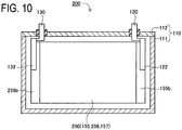
- a lithium ion secondary battery 100 is a rectangular sealed-type lithium ion secondary battery provided with a rectangular battery case 110, a positive terminal 120, and a negative terminal 130 as shown in Fig. 3 .
- the battery case 110 is made of metal and has a rectangular container section 111 constituting a containing space having a rectangular shape and a metallic cover 112.
- an electrode plate assembly 150, a positive current collector 122, a negative current collector 132, and others are contained.
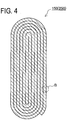
- the electrode plate assembly 150 has an elliptical shape in cross section as shown in Fig. 4 and is a flat-shaped wound body formed by winding a sheet-shaped positive electrode plate 155, a sheet-shaped negative electrode plate 156, and sheet-shaped separators 157 as shown in Fig. 5 .
- the electrode plate assembly 150 has: a positive electrode wound section 155b that is located at an end (the right end in Fig. 3 ) thereof in the axis direction (the transverse direction in Fig. 3 ) and is formed by overlapping only parts of the positive electrode plate 155 in whorl; and a negative electrode wound section 156b that is located at the other end (the left end in Fig.
- the portion excluding the positive electrode wound section 155b of the positive electrode plate 155 is coated with a positive electrode composite material 152 containing a positive active material 153 (refer to Fig. 5 ).
- the portion excluding the negative electrode wound section 156b of the negative electrode plate 156 is coated with a negative electrode composite material 159 containing a negative active material 154 (refer to Fig. 5 ).
- the positive electrode wound section 155b is electrically connected to the positive terminal 120 through the positive current collector 122.
- the negative electrode wound section 156b is electrically connected to the negative terminal 130 through the negative current collector 132.
- LiFePO 4 is used as the positive active material 153.
- a carbonaceous material of a natural graphite type is used as the negative active material 154. More specifically, a natural graphite type material of 20 ⁇ m in average particle diameter, 0.67 nm in lattice constant C0, 27 nm in crystallite size Lc, and 0.9 or more in graphitization degree is used.
- the theoretical electric capacity of a lithium ion secondary battery 100 is about 2.2 Ah.
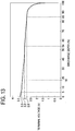
- Fig. 6 is a graph showing the charging characteristics of the lithium ion secondary battery 100 and Fig. 7 is a graph showing the discharging characteristics of the same.
- Fig. 6 shows the fluctuation of terminal voltage between the positive terminal 120 and the negative terminal 130 when the lithium ion secondary battery 100 is charged with a current value of 1 C.
- Fig. 7 shows the fluctuation of terminal voltage between the positive terminal 120 and the negative terminal 130 when the lithium ion secondary battery 100 is discharged with a current value of 1 C.
- the current value 1 C is a current value that allows the lithium ion secondary battery 100 to be charged for an hour up to the theoretical electric capacity that can be accumulated theoretically to the maximum in the positive active material 153 (LiFePO 4 ) contained in the lithium ion secondary battery 100.
- the lithium ion secondary battery 100 is characterized by, in both the cases of charging and discharging with an electric current of 1 C, being able to secure a flat charge-discharge capacity range FC that: accounts for 50% or more of the electric capacity range having the theoretical electric capacity as the upper limit (the range of 0 to 100% charged state in Fig. 6 and the range of 0 to 100% discharged state in Fig. 7 ); and has the terminal voltage fluctuation of 0.2 V or lower.
- the maximum flat charge-discharge capacity range FCmax that is the widest range of the flat charge-discharge capacity range FC of the lithium ion secondary battery 100 takes the range corresponding to about 80% of the theoretical electric capacity (the range of 15% to 95% charged state in Fig. 6 and the range of 5% to 85% discharged state in Fig. 7 ).
- the lithium ion secondary battery 100 can be charged and discharged mostly in the flat charge-discharge capacity range FC and hence can be charged and discharged while the fluctuation of voltage is reduced (while the fluctuation of the internal resistance in the battery is reduced). By so doing, it is possible to obtain a stable output characteristic (IV characteristic) of a small output fluctuation.
- the lithium ion secondary battery 100 can secure the flat charge-discharge capacity range FC corresponding to about 80% of the theoretical electric capacity at a relatively high discharging voltage of 3.4 to 3.2 V as shown in Fig. 7 . As a result, it is possible to charge and discharge the lithium ion secondary battery 100 at a relatively high battery voltage of 3.4 to 3.2 V over the capacity range of about 80% of the theoretical electric capacity and hence a high output can be obtained stably.
- the change rate of the terminal voltage per a charged electric quantity corresponding to 1% of the theoretical electric capacity increases sharply when the electric capacity exceeds the upper limit of the maximum flat charge-discharge capacity range FCmax and the end stage of charging comes; and takes a value of about 5.0 x 10 -1 (V) at the terminal voltage in the vicinity of 4.05 V (the electric capacity is about 99% of the theoretical electric capacity).
- the lithium ion secondary battery 100 is characterized in that the change rate D1 (V/Ah) of the terminal voltage per unit charged electric quantity and the change rate D2 (V/s) of the terminal voltage per unit time increase as the electric capacity comes close to the theoretical electric capacity in the end stage of charging when the lithium ion secondary battery 100 is charged until the electric capacity reaches the theoretical electric capacity (100% charged state in Fig. 6 ).
- a double-dotted line indicates the fluctuation of the terminal voltage when a lithium ion secondary battery (a comparative example) different from the lithium ion secondary battery 100 only in changing the positive active material to LiCoO 2 is charged with an electric current of 1 C.
- the terminal voltage rises by about 0.55 V (rises from 3.55 V to 4.1 V) when the battery is charged with an electric quantity corresponding to the range of 15% to 95% of the theoretical electric capacity of the lithium ion secondary battery 100, with an electric current of 1 C.
- the lithium ion secondary battery 100 of the first embodiment when the lithium ion secondary battery 100 of the first embodiment is charged and discharged mostly in the flat charge-discharge capacity range FC, the lithium ion secondary battery 100 can be charged and discharged while the voltage fluctuation is reduced more (while the fluctuation of the internal resistance in the battery is reduced more) in comparison with the case where a lithium ion secondary battery using LiCoO 2 as the positive active material is charged and discharged in the same range.
- the production method of the lithium ion secondary battery 100 of the first embodiment is explained below.
- positive electrode slurry is produced by blending LiFePO 4 (the positive active material 153), acetylene black (an auxiliary conductive agent), and polyvinylidene fluoride (a binder resin) at the ratio of 85:5:10 (in weight ratio) and adding N-methylpyrolidone (a dispersion solvent) to the mixture.
- the surface of an aluminum foil 151 is coated with the positive electrode slurry and the coated aluminum foil 151 is dried and thereafter subjected to press forming.
- the positive electrode plate 155 produced by coating the surface of the aluminum foil 151 with the positive electrode composite material 152 is obtained (refer to Fig. 5 ).
- negative electrode slurry is produced by blending a natural graphite type carbonaceous material (the negative active material 154), a styrene-butadiene copolymer (a binder resin), and carboxymethylcellulose (a thickening agent) at the ratio of 95:2.5:2.5 (in weight ratio) in water.
- a copper foil 158 is coated with the negative electrode slurry and the coated copper foil 158 is dried and thereafter subjected to press forming.
- a negative electrode plate 156 produced by coating the surface of the copper foil 158 with a negative electrode composite material 159 is obtained (refer to Fig. 5 ).
- the natural graphite type carbonaceous material a natural graphite type material of 20 ⁇ m in average particle diameter, 0.67 nm in lattice constant C0, 27 nm in crystallite size Lc, and 0.9 or more in graphitization degree is used.
- the coating amounts of the positive electrode slurry and the negative electrode slurry are adjusted so that the ratio of the theoretical capacity of the positive pole to the theoretical capacity of the negative pole may be 1:1.5.
- the positive electrode plate 155, the negative electrode plate 156, and the separators 157 are laminated and wound into the electrode plate assembly 150 having an elliptical shape in cross section (refer to Figs. 4 and 5 ).
- the positive electrode plate 155, the negative electrode plate 156, and the separators 157 are laminated, the positive electrode plate 155 is disposed so that the part of the positive electrode plate 155 not coated with the positive electrode composite material 152 may protrude from an end of the electrode plate assembly 150.
- the negative electrode plate 156 is disposed so that the part of the negative electrode plate 156 not coated with the negative electrode composite material 159 may protrude from the side opposite the non-coated part of the positive electrode plate 155.
- the electrode plate assembly 150 having the positive electrode wound section 155b and the negative electrode wound section 156b (refer to Fig. 3 ) is formed.
- separators 157 a composite porous film comprising a three-layer structure of polypropylene, polyethylene, and polypropylene is used.
- the positive electrode wound section 155b of the electrode plate assembly 150 is connected to the positive terminal 120 through the positive current collector 122. Further, the negative electrode wound section 156b of the electrode plate assembly 150 is connected to the negative terminal 130 through the negative current collector 132. Thereafter, they are contained in the rectangular container 111, the rectangular container 111 and the cover 112 are welded together, and the battery case 110 is sealed. Successively, an electrolyte is poured through a liquid inlet (not shown in the figures) disposed on the cover 112, thereafter the liquid inlet is sealed, and thus the lithium ion secondary battery 100 of the first embodiment is completed.
- a liquid produced by dissolving 1 mole of lithium hexafluorophosphate (LiPF 6 ) in a solution produced by blending EC (ethylene carbonate) and DEC (diethyl carbonate) at the ratio of 4:6 (in volume ratio) is used.
- the charging voltage upper limit Vmax is varied to 3.6 V, 3.8 V, and 4.05 V and the first capacity of each case is measured as an example. More specifically, firstly constant electric current charging is applied with an electric current of 1/5 C until the terminal voltage reaches the charging voltage upper limit Vmax. Thereafter, constant voltage charging is applied at the charging voltage upper limit Vmax and the charging is terminated when the current value of the charging lowers to one tenth of the current value at the commencement of the constant voltage charging. Successively, another constant electric current discharging is applied with an electric current of 1/5 C until the terminal voltage reaches 3 V, and the discharged electric quantity at the time is obtained as the first capacity.
- the charging voltage upper limit Vmax is varied to 4.2 V and 4.5 V respectively and the first capacity of each case is measured.
- Table 1 Charging voltage upper limit Vmax (V) Charging capacity per 1g of positive active material (mAh/g) First capacity (Ah) First capacity maintenance ratio (%) in cycle test 100 cycles 500 cycles 1000 cycles
- Comparative Example (LiCoO2) 4.25 158 2.00 92 77 52 4.5 169 2.20 58 0 -
- the first capacities when the charging voltage upper limit Vmax is set at 3.6 V, 3.8 V, and 4.05 V as an example are 2.00 Ah, 2.04 Ah, and 2.05 Ah, respectively.
- both the first capacities when the charging voltage upper limit Vmax is set at 4.2 V and 4.5 V as the comparative example are 2.05 Ah and are identical to the first capacity when the charging voltage upper limit Vmax is set at 4.05 V. From the results, it is possible to exhibit satisfactory charge-discharge performance of the lithium ion secondary battery 100 even when the charging voltage upper limit Vmax is set to be as low as about 4.05 V and thereby it is possible to inhibit the oxidative decomposition of an electrolyte.
- cycle tests are carried out by varying the charging voltage upper limit Vmax to 3.6 V, 3.8 V, and 4.05 V as an example. More specifically, under the environment of 25°C in temperature, constant electric current charging is applied with an electric current of 5 C until the terminal voltage reaches a charging voltage upper limit Vmax. Thereafter, constant voltage charging is further applied at the charging voltage upper limit Vmax and the charging is terminated when the current value of the charging lowers to one tenth of the current value at the commencement of the constant voltage charging. Successively, constant electric current discharging is applied with an electric current of 5 C until the terminal voltage reaches 3 V.
- the above combination of the charging and the discharging is regarded as one cycle and the cycle of the charging and discharging is repeated a thousand times.
- the discharge capacities at 100th, 500th, and 1000th cycles are measured respectively and the ratios of the discharge capacities to the first capacities are computed as first capacity maintenance ratios (%).
- cycle tests similar to the above example are carried out by varying the charging voltage upper limit Vmax of the lithium ion secondary battery 100 at 4.2 V and 4.5 V as a comparative example and first capacity maintenance ratios (%) are computed.
- a lithium ion secondary battery different from the lithium ion secondary battery 100 only in changing the positive active material into LiCoO 2 is produced.
- the charging voltage upper limit Vmax is varied to 4.25 V and 4.5 V and the first capacities are measured and the first capacity maintenance ratios (%) are computed by the cycle tests in the same way as the example. The results are shown in Table 1.
- the first capacity maintenance ratio lowers to 52% after 1000th cycle.
- the discharging capacity is not secured at the 500th cycle. This is presumably because the oxidative decomposition of an electrolyte proceeds because of a high charging voltage upper limit Vmax of 4.2 V or higher and affects the results.
- the first capacity in the comparative example is nearly equal to the first capacity of the lithium ion secondary battery 100 when the charging voltage upper limit Vmax is set at 3.6 V to 4.05 V. Consequently, from the result, it can be said that, by charging and discharging the lithium ion secondary battery 100 while setting the charging voltage upper limit Vmax at 3.6 V to 4.05 V, it is possible to drastically improve the lifetime characteristic of the battery while securing an identical electric quantity in comparison with the case of charging and discharging the lithium ion secondary battery using LiCoO 2 as the positive active material while setting the charging voltage upper limit Vmax at 4.25 V. In particular, it is also possible to obtain a high output by charging and discharging the lithium ion secondary battery 100 while setting the charging voltage upper limit Vmax at about 4.05 V.
- a charge-discharge control method for controlling the charging and discharging of a battery pack 10 of the first embodiment is explained below.
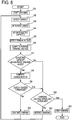
- Step S1 the electric current flowing in the lithium ion secondary batteries 100 is detected with the current detector 50.
- Step S3 the current value I detected with the current detector 50 is integrated and the charged electric quantity of the lithium ion secondary batteries 100 is computed.
- Step S4 the battery controller 30 estimates the electric capacity stored in the lithium ion secondary batteries 100 from the computed charged electric quantity.
- Step S5 the voltage detector 40 detects the terminal voltage V of each of the lithium ion secondary batteries 100.
- Step S6 the average of the terminal voltages V detected with the voltage detector 40 (the average terminal voltage Va) of the lithium ion secondary batteries 100 is computed.
- the lithium ion secondary battery 100 has the property of being able to secure a flat charge-discharge capacity range FC as stated above. Consequently, when the battery is charged in the maximum flat charge-discharge capacity range FCmax, the fluctuation of the terminal voltage is small and hence it is difficult to accurately compute the charged electric quantity by a method for computing the charged electric quantity in the battery based on the terminal voltage.
- the value I of the electric current flowing in the lithium ion secondary batteries 100 is integrated and the charged electric quantity is computed as stated above. By so doing, it is possible to compute the charged electric quantity with a high degree of accuracy even in the maximum flat charge-discharge capacity range FCmax.
- the predetermined range of the electric capacity is set at the range of 0.4 Ah to 2.0 Ah and the range is stored in advance in the ROM 31 of the battery controller 30.
- the process proceeds to Step S8 and the change rate D1 (V/Ah) of the average terminal voltage Va per unit charged electric quantity is computed based on the current value I integrated from the start of the charging and the variation of the average terminal voltage Va.
- the change rate D1 exceeds a predetermined threshold K.
- the first threshold K1 is set at 10 (V/Ah).
- Step S9 When the change rate D1 is judged not to exceed the first threshold K1 (No) at Step S9, the process proceeds to Step SA and the charging is continued. Thereafter, the process goes back to Step S2 and the above series of processing is applied.
- Step SB the charging voltage upper limit Vmax is set at 4.05 V.
- Step SB When the average terminal voltage Va is judged not to reach the charging voltage upper limit Vmax (No) at Step SB, the process proceeds to Step SC and the charging of the lithium ion secondary batteries 100 is restricted. More specifically, by applying intermittent charging wherein charging and non-charging are repeated for example, it is possible to restrict the charging of the lithium ion secondary batteries 100. Thereafter, the process goes back to Step S2 and the above series of processing is applied.
- Step SB when the average terminal voltage Va is judged to reach the charging voltage upper limit Vmax (Yes) at Step SB, the process proceeds to Step SD and the charging of the lithium ion secondary batteries 100 is stopped.
- a discharge control method is explained below in reference to Fig. 9 .
- the lithium ion secondary batteries 100 constituting the battery pack 10 start to be discharged by the control of the battery controller 30 at Step U1, then the process proceeds to Step U2, and the electric current flowing in the lithium ion secondary batteries 100 is detected with the current detector 50. Successively, the process proceeds to Step U3 and the current value I detected with the current detector 50 is integrated and the discharged electric quantity of the lithium ion secondary batteries 100 is computed. Successively, the process proceeds to Step U4 and the battery controller 30 estimates the electric capacity stored in the lithium ion secondary batteries 100 from the computed discharged electric quantity.
- Step U5 the voltage detector 40 detects the terminal voltage V of each of the lithium ion secondary batteries 100. Thereafter, the process proceeds to Step U6 and the average of the terminal voltages V detected with the voltage detector 40 (the average terminal voltage Va) of the lithium ion secondary batteries 100 is computed.
- Step U7 the process proceeds to Step U7 and whether or not the estimated electric capacity is within a predetermined range is judged.
- the process proceeds to Step U8 and the discharging is continued. Thereafter, the process goes back to Step U2 and the above series of processing is applied.
- the process proceeds to Step U9 and it is determined whether or not the average terminal voltage Va reaches the discharging voltage lower limit Vmin.
- the discharging voltage lower limit Vmin is set at 3.0 V and the value is stored in advance in the ROM 31 of the battery controller 30.
- Step U9 When the average terminal voltage Va is judged not to reach the discharging voltage lower limit Vmin (No) at Step U9, the process proceeds to Step UA and the discharging of the lithium ion secondary batteries 100 is restricted. More specifically, by applying intermittent discharging wherein discharging and non-discharging are repeated alternately for example, it is possible to restrict the discharging of the lithium ion secondary batteries 100. Thereafter, the process goes back to Step U2 and the above series of processing is applied.
- Step U9 when the average terminal voltage Va is judged to reach the discharging voltage lower limit Vmin (Yes) at Step U9, the discharging of the lithium ion secondary batteries 100 is stopped at Step UB.
- the lithium ion secondary battery 100 constituting the battery pack 10 is charged and discharged in the electric capacity range wherein the average terminal voltage Va is in the range of 3.0 V to 4.05 V.
- the electric capacity range wherein the terminal voltage is in the range of 3.0 V to 4.05 V corresponds to the range wherein the electric capacity is about 7% to 99% as it is obvious in reference to Fig. 6 .
- FCmax the range wherein the electric capacity is about 15% to 95%)
- Steps S2 and U2 correspond to the current detection step. Further, Steps S3 and U3 correspond to the electric quantity computation step. Then Steps S4 and U4 correspond to the electric capacity estimation step. Furthermore, Steps S5 and U5 correspond to the voltage detection step. Yet further, Steps S8 to SD and U9 to UB correspond to the charge-discharge control step. In the steps, Steps SD and UB correspond to the charging stop step, Step S8 corresponds to the change rate computation step, and Step SC corresponds to the charging restriction step.
- the process of Step S4 is repeated from the commencement of charging to the stop of the charging and the process of Step U4 is also repeated from the commencement of discharging to the stop of the discharging.
- the process corresponding to the electric capacity estimation step (Steps S4 and U4) is applied to each of the lithium ion secondary batteries 100 constituting the battery pack 10 over the electric capacity range FP including at least a part of the maximum flat charge-discharge capacity range FCmax (refer to Fig. 6 ). More specifically, the process corresponding to the electric capacity estimation step (Steps S4 and U4) is applied over the charge-discharge capacity range X including the maximum flat charge-discharge capacity range FCmax (refer to Fig. 6 ). As a result, the electric capacity can be estimated based on the integrated current value in the maximum flat charge-discharge capacity range FCmax wherein the fluctuation of the battery voltage is small and hence it is possible to estimate the electric capacity appropriately.
- a hybrid electric vehicle 9 of the second embodiment is different from the hybrid electric vehicle 1 of the first embodiment in mounting a battery pack system 16 in place of the battery pack system 6 as shown with the parentheses in Fig. 1 and the others are the same.
- the battery pack system 16 of the second embodiment is different from the battery pack system 6 of the first embodiment in changing the battery pack 10 into a battery pack 20 as shown with the parentheses in Fig. 2 and the others are the same.
- the battery pack 20 of the second embodiment is different from the battery pack 10 of the first embodiment in using lithium ion secondary batteries 200 instead of the lithium ion secondary batteries 100 and the others are the same.
- Each of the lithium ion secondary batteries 200 is different from each of the lithium ion secondary batteries 100 of the first embodiment in changing the negative electrode plate 156 into a negative electrode plate 256 as shown in Fig. 10 and the others are the same.
- the negative electrode plate 256 of the second embodiment is different from the negative electrode plate 156 of the first embodiment in the negative active material.
- Li 4 Ti 5 O 12 is used as the negative active material 254 in the second embodiment and the negative electrode plate 256 is produced by forming a sintered compact 259 comprising Li 4 Ti 5 O 12 on the surface of a copper foil 158 and press-forming the copper foil 158 (refer to Fig. 5 ).
- the lithium ion secondary batteries 200 of the second embodiment are produced in the same way as the lithium ion secondary batteries 100 of the first embodiment.
- the theoretical electric capacity of each of the lithium ion secondary batteries 200 is about 2.2 Ah.
- Fig. 11 is a graph showing the charging characteristics of the lithium ion secondary battery 200 and Fig. 12 is a graph showing the discharging characteristics of the same.
- Fig. 11 shows the fluctuation of terminal voltage between the positive terminal 120 and the negative terminal 130 when the lithium ion secondary battery 200 is charged with a current value of 1 C.
- Fig. 12 shows the fluctuation of terminal voltage between the positive terminal 120 and the negative terminal 130 when the lithium ion secondary battery 200 is discharged with a current value of 1 C.
- the current value 1 C is a current value that allows the lithium ion secondary battery 200 to be charged for an hour up to the theoretical electric capacity that can be accumulated theoretically to the maximum in the positive active material 153 (LiFePO 4 ) contained in the lithium ion secondary battery 200.
- the lithium ion secondary battery 200 is characterized by, in both the cases of charging and discharging with an electric current of 1 C, being able to secure a flat charge-discharge capacity range FC that: accounts for 50% or more of the electric capacity range having the theoretical electric capacity as the upper limit (the range of 0 to 100% charged state in Fig. 11 and the range of 0 to 100% discharged state in Fig. 12 ); and has the terminal voltage fluctuation of 0.2 V or lower.
- the maximum flat charge-discharge capacity range FCmax that is the widest range of the flat charge-discharge capacity range FC of the lithium ion secondary battery 200 takes the range corresponding to about 95% of the theoretical electric capacity (the range of about 3% to 98% charged state in Fig. 11 and the range of about 2% to 97% discharged state in Fig. 12 ).
- the lithium ion secondary battery 200 can be charged and discharged mostly in the flat charge-discharge capacity range FC and hence can be charged and discharged while the fluctuation of voltage is reduced (while the fluctuation of the internal resistance in the battery is reduced). By so doing, it is possible to obtain a stable output characteristic (IV characteristic) of a small output fluctuation.
- the fluctuation of the terminal voltage is as small as 0.05 V (lowers from 1.99 V to 1.94 V). As a result, it is possible to obtain a very stable output when the lithium ion secondary battery 200 is discharged in the range.
- the average change rate of terminal voltage per an electric capacity corresponding to 1% of the theoretical electric capacity in the flat charge-discharge capacity range FC1 ranging from about 3% to 90% of the theoretical electric capacity is about 6 x 10 -4 V.
- the terminal voltage is about 2.05 V at the upper limit of the flat charge-discharge capacity range FC1.
- the change rate of terminal voltage per an electric capacity corresponding to 1% of the theoretical electric capacity increases when the electric capacity exceeds the upper limit of the flat charge-discharge capacity range FC1 (about 90% of the theoretical electric capacity) and the end stage of charging comes; and takes a value of 3.0 x 10 -1 (V) or more at a terminal voltage in the vicinity of 2.4 V (the electric capacity is about 99% of the theoretical electric capacity).
- the lithium ion secondary battery 200 is characterized in that the change rate D1 (V/Ah) of terminal voltage per unit charged electric quantity and the change rate D2 (V/s) of terminal voltage per unit time increase as the electric capacity comes close to the theoretical electric capacity in the end stage of charging when the lithium ion secondary battery 200 is charged until the electric capacity reaches the theoretical electric capacity (100% charged state in Fig. 11 ).
- the charging voltage upper limit Vmax is set at 2.4 V and the value is stored in the ROM 31 of the battery controller 30.
- the first threshold K1 is set at 2.5 V/Ah and the value is stored in the ROM 31 of the battery controller 30.
- the ratio of the range X belonging to the maximum flat charge-discharge capacity range FCmax with respect to the range X is set at about 97% (refer to Fig. 11 ).
- the charging voltage upper limit Vmax is varied to 2.1 V, 2.2 V, and 2.4 V and the first capacity of each case is measured as an example. More specifically, constant electric current charging is first applied with an electric current of 1/5 C until the terminal voltage reaches the charging voltage upper limit Vmax. Thereafter, constant voltage charging is applied at the charging voltage upper limit Vmax and the charging is terminated when the current value of the charging lowers to one tenth of the current value at the commencement of the constant voltage charging. Successively, constant electric current discharging is applied with an electric current of 1/5 C until the terminal voltage reaches 1.7 V, and the discharged electric quantity at the time is obtained as the first capacity.
- the charging voltage upper limit Vmax is varied to 3 V and 4 V and the first capacity of each case is measured.
- the results are shown in Table 2.
- Table 2 Charging voltage upper limit Vmax (V) Charging capacity per 1g of positive active material (mAh/g) First capacity (Ah) First capacity maintenance ratio (%) in cycle test 100 cycles 500 cycles 1000 cycles
- the first capacities when the charging voltage upper limit Vmax is set at 2.1 V, 2.2 V, and 2.4 V as an example are 2.00 Ah, 2.04 Ah, and 2.05 Ah, respectively.
- the first capacities when the charging voltage upper limit Vmax is set at 3 V and 4 V as a comparative example are 2.05 Ah in both the cases and are identical to the first capacity when the charging voltage upper limit Vmax is set at 2.4 V. From the results, it is possible to exhibit satisfactory charge-discharge performance of the lithium ion secondary battery 200 even when the charging voltage upper limit Vmax is set at a low value of about 2.4 V and thereby it is possible to inhibit the oxidative decomposition of an electrolyte.
- cycle tests are carried out by varying the charging voltage upper limit Vmax to 2.1 V, 2.2 V, and 2.4 V as an example. More specifically, under the environment of 25°C in temperature, constant electric current charging is applied with an electric current of 5 C until the terminal voltage reaches a charging voltage upper limit Vmax. Thereafter, constant voltage charging is further applied at the charging voltage upper limit Vmax and the charging is terminated when the current value of the charging lowers to one tenth of the current value at the commencement of the constant voltage charging. Successively, constant electric current discharging is applied with an electric current of 5 C until the terminal voltage reaches 1.7 V.
- the above combination of the charging and the discharging is regarded as one cycle and the cycle of the charging and discharging is repeated a thousand times.
- the discharge capacities at 100th, 500th, and 1000th cycles are measured respectively and the ratios of the discharge capacities to the first capacities are computed as first capacity maintenance ratios (%).
- cycle tests similar to the above example are carried out by varying the charging voltage upper limit Vmax of the lithium ion secondary battery 200 to 3 V and 4 V as a comparative example and first capacity maintenance ratios (%) are computed.
- a lithium ion secondary battery different from the lithium ion secondary battery 200 only in changing the positive active material into LiCoO 2 is produced.
- the charging voltage upper limit Vmax is varied to 4.25 V and 4.5 V and the first capacities are measured and the first capacity maintenance ratios (%) are computed by the cycle tests in the same way as the example. The results are shown in Table 2.
- the first capacity maintenance ratio lowers to 70% after 100th cycle and the discharge capacity cannot be secured at 500th cycle.
- the first capacity maintenance ratio lowers to 17% after 100th cycle and the discharge capacity cannot be secured at 500th cycle. This is presumably because the quantity of an electrolyte reduces and a film is formed on the active material surface in accordance with the progress of the oxidative decomposition of the electrolyte and, as a result, overvoltage rises during charging and discharging.
- the first capacity maintenance ratio lowers to 52% after 1000th cycle.
- the discharging capacity is not secured at the 500th cycle. This is presumably because the oxidative decomposition of an electrolyte proceeds because of a high charging voltage upper limit Vmax of 4.2 V or higher and affects the results.
- the first capacity in the comparative example is nearly equal to the first capacity of the lithium ion secondary battery 200 when the charging voltage upper limit Vmax is set at 2.1 V to 2.4 V. Consequently, from the result, it can be said that, by charging and discharging the lithium ion secondary battery 200 while setting the charging voltage upper limit Vmax at 2.1 V to 2.4 V, it is possible to drastically improve the lifetime characteristic of the battery while securing an identical electric quantity in comparison with the case of charging and discharging the lithium ion secondary battery using LiCoO 2 as the positive active material while setting the charging voltage upper limit Vmax at 4.25 V.
- a charge-discharge control method for controlling the charging and discharging of a battery pack 20 of the second embodiment is explained below.
- Step S1 After the lithium ion secondary batteries 200 constituting the battery pack 20 start to be charged at Step S1, the processes of Steps S2 to S6 are applied in the same way as the first embodiment. At Step S7, successively, it is determined whether or not the estimated electric capacity is within a predetermined range.
- the predetermined range of the electric capacity is set at the range of 0.4 Ah to 2.0 Ah in the same way as the first embodiment.
- Step S8 the change rate D1 (V/Ah) of the average terminal voltage Va per unit charged electric quantity is computed based on the current value I integrated from the start of the charging and the variation of the average terminal voltage Va. It is then determined at Step S9 whether or not the change rate D1 exceeds a predetermined first threshold K1.
- the first threshold K1 is set at 2.5 (V/Ah).
- Step S9 When the change rate D1 is judged not to exceed the first threshold K1 (No) at Step S9, the process proceeds to Step SA and the charging is continued. Thereafter, the process goes back to Step S2 and the above series of processing is applied.
- Step SB the charging voltage upper limit Vmax is set at 2.4 V.
- Step SB When the average terminal voltage Va is judged not to reach the charging voltage upper limit Vmax (No) at Step SB, the process proceeds to Step SC and the charging of the lithium ion secondary batteries 200 is restricted. Thereafter, the process goes back to Step S2 and the above series of processing is applied. Meanwhile, when the average terminal voltage Va is judged to reach the charging voltage upper limit Vmax (Yes) at Step SB, the process proceeds to Step SD and the charging of the lithium ion secondary batteries 200 is stopped.
- Step U1 After the lithium ion secondary batteries 200 constituting the battery pack 20 start to be discharged firstly at Step U1, the processes of Steps U2 to U6 are applied in the same way as the first embodiment. Successively, the process proceeds to Step U7 and whether or not the estimated electric capacity is within a predetermined range is judged. When the estimated electric capacity is judged to be in the predetermined range (0.4 Ah to 2.0 Ah) (Yes), the process proceeds to Step U8 and the discharging is continued. Thereafter, the process goes back to Step U2 and the above series of processing is applied.
- the process proceeds to Step U9 and whether or not the average terminal voltage Va reaches the discharging voltage lower limit Vmin is judged.
- the discharging voltage lower limit Vmin is set at 1.7 V.
- Step U9 When the average terminal voltage Va is judged not to reach the discharging voltage lower limit Vmin (No) at Step U9, the process proceeds to Step UA and the discharging of the lithium ion secondary batteries 200 is restricted. Thereafter, the process goes back to Step U2 and the above series of processing is applied.
- Step U9 when the average terminal voltage Va is judged to reach the discharging voltage lower limit Vmin (Yes) at Step U9, the process proceeds to Step UB and the discharging of the lithium ion secondary batteries 200 is stopped.
- the lithium ion secondary batteries 200 constituting a battery pack 20 are charged and discharged in the electric capacity range wherein the average terminal voltage Va is in the range of 1.7 V to 2.4 V.
- the electric capacity range wherein the average terminal voltage Va is in the range of 1.7 V to 2.4 V corresponds to the range wherein the electric capacity is about 1.5% to 99.5% as it is obvious in reference to Fig. 11 .
- FCmax the range wherein the electric capacity is about 3% to 98%)
- lithium ion secondary batteries 100 and 200 characterized by being able to secure a flat charge-discharge capacity range FC can be produced by using LiFePO 4 as the positive active material.
- a positive electrode produced by using LiFePO 4 as the positive active material is characterized by being able to charge and discharge an electric quantity in the range corresponding to about 80% of the theoretical electric capacity with scarce potential fluctuation at a charge-discharge potential in the vicinity of 3.4 V when the battery is charged and discharged with an electric current of 1 C.
- the battery voltage tends to reduce gradually during discharging and flat charge-discharge capacity range cannot be secured as shown in Fig. 13 . More specifically, the capacity range wherein the fluctuation of terminal voltage is 0.2 V or lower during discharging with an electric current of 1 C is about 35% of the theoretical electric capacity and is smaller than 50%.
- a negative electrode produced by using a negative active material of an alloy type is characterized in that the potential increases and decreases gradually over the whole charge-discharge range during charging and discharging with an electric current of 1 C; and does not have a capacity range wherein the battery can be charged and discharged while the potential scarcely fluctuates.
- LiFePO 4 is used as the positive active material, it is impossible to obtain a lithium ion secondary battery characterized by being able to secure a flat charge-discharge capacity range unless a material, such as a carbonaceous material or a Li 4 Ti 5 O 12 type material, characterized by allowing charging and discharging with a small potential fluctuation (fluctuation of 0.2 V or less) over the range of not less than 50% of the positive electrode theoretical capacity is used as the negative active material.
- a material such as a carbonaceous material or a Li 4 Ti 5 O 12 type material
- an change rate D1 (V/Ah) of terminal voltage per unit charged electric quantity is computed at Step S7 and, when the change rate D1 is judged to exceed the first threshold K1 (V/Ah) at Step S8, the charging of the lithium ion secondary batteries 100 is restricted at Step SA.
- the lithium ion secondary batteries 100 when the lithium ion secondary batteries 100 are charged with an electric current of 1 C, it is possible to restrict the charging of the lithium ion secondary batteries 100 appropriately by setting the second threshold K2 at 6 x 10 -3 (V/s) for example.
Landscapes
- Engineering & Computer Science (AREA)
- Chemical & Material Sciences (AREA)
- Chemical Kinetics & Catalysis (AREA)
- Electrochemistry (AREA)
- General Chemical & Material Sciences (AREA)
- Manufacturing & Machinery (AREA)
- Materials Engineering (AREA)
- Power Engineering (AREA)
- Inorganic Chemistry (AREA)
- Microelectronics & Electronic Packaging (AREA)
- Secondary Cells (AREA)
- Life Sciences & Earth Sciences (AREA)
- Sustainable Energy (AREA)
- Transportation (AREA)
- Mechanical Engineering (AREA)
- Sustainable Development (AREA)
- Charge And Discharge Circuits For Batteries Or The Like (AREA)
- Battery Electrode And Active Subsutance (AREA)
- Battery Mounting, Suspending (AREA)
- Electric Propulsion And Braking For Vehicles (AREA)
- Hybrid Electric Vehicles (AREA)
Claims (8)
- Batteriepacksystem (6) mit:einem Batteriepack (10), das eine Vielzahl von Lithiumionenakkumulatoren (100) aufweist, die elektrisch in Reihe miteinander verbunden sind, wobei jede der Lithiumionenakkumulatoren enthält: eine positive Elektrodenplatte, die ein positives aktives Material enthält; einen positiven Anschluss, der elektrisch mit der positiven Elektrodenplatte verbunden ist; eine negative Elektrodenplatte, die ein negatives aktives Material enthält; und einen negativen Anschluss, der elektrisch mit der negativen Elektrodenplatte verbunden ist, undwobei das Batteriepacksystem ferner aufweisteine Ladungs-/Entladungssteuerungseinrichtung (30) zum Laden und Entladen jeder der Lithiumionenakkumulatoren in einem Ladungs-/Entladungskapazitätsbereich, der zumindest einen Teil eines maximalen flachen Ladungs-/Entladungskapazitätsbereiches enthält, der als ein breitester Bereich des flachen Ladungs-/Entladungskapazitätsbereiches von jeder der Lithiumionenakkumulatoren definiert ist,gekennzeichnet durcheine Änderungsratenberechnungseinrichtung zum Berechnen einer Änderungsrate der Anschlussspannung pro geladener elektrischer Einheitsmenge oder einer Änderungsrate der Anschlussspannung pro Einheitszeit während zumindest eines Ladens von jeder der Lithiumionenakkumulatoren,wobei jeder Lithiumionenakkumulator eine Eigenschaft des Anwachsens der Änderungsrate der Anschlussspannung pro geladener elektrischer Einheitsmenge und der Änderungsrate der Anschlussspannung pro Einheitszeit hat, wenn die elektrische Kapazität nahe an die theoretische elektrische Kapazität in einem Endstadium des Ladens kommt, wenn jeder der Lithiumionenakkumulatoren geladen wird, bis die elektrische Kapazität die theoretische elektrische Kapazität erreicht,die Ladungs-/Entladungssteuerungseinrichtung eine Ladungsbeschränkungseinrichtung aufweist zum Beschränken eines Ladens von jeder der Lithiumionenakkumulatoren, wenn:die Änderungsrate der Anschlussspannung pro geladener elektrischer Einheitsmenge, die durch die Änderungsratenberechnungseinrichtung berechnet wird, eine erste vorbestimmte Spannung übersteigt, die größer als eine durchschnittliche Änderungsrate der Anschlussspannung pro geladener elektrischer Einheitsmenge in dem maximalen flachen Ladungs-/Entladungskapazitätsbereich ist, oderdie Änderungsrate der Anschlussspannung pro Einheitszeit, die durch die Änderungsratenberechnungseinrichtung berechnet wird, einen zweiten vorbestimmten Schwellwert, der größer als eine durchschnittliche Änderungsrate der Anschlussspannung pro Einheitszeit in dem maximalen flachen Ladungs-/Entladungskapazitätsbereich ist, überschreitet,
dadurch gekennzeichnet, dassdas positive aktive Material LiFe(1-x)MxPO(4) ist, wobei M zumindest eins aus Mn, Cr, Co, Cu, Ni, V, Mo, Ti, Zn, AI, Ga, Mg, B und Nb ist und X durch einen Ausdruck 0 ≤ X ≤ 0,5 bestimmt wird, das negative aktive Material eines aus einem kohlenstoffhaltigen Material und einem Li4Ti5O12 Typ-Material ist, und wobei der Lithiumionenakkumulator eine Eigenschaft hat, dass er in der Lage ist, einen flachen Ladungs-/Entladungskapazitätsbereich sicherzustellen, der definiert ist als ein Kapazitätsbereich, der: für 50% oder mehr eines elektrischen Kapazitätsbereiches zuständig ist, der als eine obere Grenze eine theoretische elektrische Kapazität hat, die theoretisch bis zum Maximum in dem positiven aktiven Material akkumuliert werden kann, und einem Bereich entspricht, in dem eine Fluktuation einer Anschlussspannung zwischen dem positiven Anschluss und dem negativen Anschluss 0,2 V oder kleiner in beiden Fällen ist, in denen die Batterie mit einem elektrischen Strom, der einen Stromwert von 1 C hat, mit dem die Batterie bis zur theoretischen elektrischen Kapazität in einer Stunde geladen werden kann, geladen oder entladen wird. - Batteriepacksystem nach Anspruch 1, wobei
ein Bereich von 80% oder mehr des Ladungs-/Entladungskapazitätsbereichs zu dem maximalen flachen Ladungs-/Entladungskapazitätsbereich gehört. - Batteriepacksystem nach Anspruch 1 oder 2, ferner mit:einer Stromerfassungseinrichtung zum Erfassen eines Wertes eines Stromes, der in jedem der Lithiumionenakkumulatoren fließt;einer Elektrischeladungsberechnungseinrichtung zum Berechnen einer geladenen elektrischen Ladung oder einer entladenen elektrischen Ladung von jeder der Lithiumionenakkumulatoren durch Integrieren des erfassten Stromwertes; undeiner Elektrischekapazitätsschätzeinrichtung zum Schätzen einer elektrischen Kapazität, die in jedem der Lithiumionenakkumulatoren in einem elektrischen Kapazitätsbereich, der zumindest einen Teil des maximalen flachen Ladungs-/Entladungskapazitätsbereiches enthält, gespeichert ist, basierend auf der berechneten elektrischen Ladungsmenge oder der berechneten elektrischen Entladungsmenge.
- Batteriepacksystem nach einem der Ansprüche 1 bis 3, wobei
das System ferner eine Spannungserfassungseinrichtung zum Erfassen einer Anschlussspannung von einer oder mehreren der Lithiumionenakkumulatoren aufweist, und
die Ladungs-/Entladungssteuereinrichtung angebracht ist, ein Laden und Entladen von jedem der Lithiumionenakkumulatoren basierend auf der erfassten Anschlussspannung zu steuern. - Batteriepacksystem nach Anspruch 4, wobei
die Ladungs-/Entladungssteuerungseinrichtung eine Ladungsanhalteeinrichtung zum Anhalten des Ladens für jeden der Lithiumionenakkumulatoren enthält, wenn die Anschlussspannung eine obere Ladungsspannungsgrenze erreicht. - Batteriepacksystem nach Anspruch 5, wobei
das negative aktive Material ein kohlenstoffhaltiges Material ist, und
die obere Ladungsspannungsgrenze auf einen Wert von 3,60 V oder höher und 4,05 V oder kleiner eingestellt ist. - Batteriepacksystem nach Anspruch 5, wobei
das negative aktive Material vom Li4Ti5O12 Typ ist, und
die obere Ladungsspannungsgrenze auf einen Wert von 2,1 V oder höher und 2,4 V oder niedriger eingestellt ist. - Batteriepacksystem nach einem der Ansprüche 1 bis 7, wobei
entweder
das negative aktive Material ein kohlenstoffhaltiges Material ist, und
die Ladungsbeschränkungseinrichtung den ersten Schwellenwert oder den zweiten Schwellenwert auf einen Wert setzt, der der Änderungsrate der Anschlussspannung pro elektrischer Kapazität, die 1% der theoretischen elektrischen Kapazität entspricht, einstellt, wobei die Änderungsrate in einen Bereich von 5,0 x 10⁻³ V oder mehr und 2,5 x 10⁻¹ V oder weniger fällt, oder
das negative aktive Material vom Li4Ti5O12 Typ ist, und
die Ladungsbeschränkungseinrichtung den ersten Schwellenwert oder den zweiten Schwellenwert auf einen Wert entsprechend der Änderungsrate der Anschlussspannung pro elektrischer Kapazität, die 1% der theoretischen elektrischen Kapazität entspricht, so einstellt, dass die Änderungsrate in einen Bereich von 1,0 x 10⁻³ V oder mehr und 1,5 x 10⁻¹ V oder weniger fällt.
Applications Claiming Priority (2)
| Application Number | Priority Date | Filing Date | Title |
|---|---|---|---|
| JP2007301848A JP5109619B2 (ja) | 2007-11-21 | 2007-11-21 | 組電池システム、及び充放電制御方法 |
| PCT/JP2008/071278 WO2009066782A2 (en) | 2007-11-21 | 2008-11-18 | Lithium ion secondary battery, battery pack, hybrid electric vehicle, battery pack system, and charge-discharge control method |
Publications (2)
| Publication Number | Publication Date |
|---|---|
| EP2160789A2 EP2160789A2 (de) | 2010-03-10 |
| EP2160789B1 true EP2160789B1 (de) | 2018-12-26 |
Family
ID=40578277
Family Applications (1)
| Application Number | Title | Priority Date | Filing Date |
|---|---|---|---|
| EP08851852.7A Active EP2160789B1 (de) | 2007-11-21 | 2008-11-18 | Batterie-pack-system mit kleiner fluktuation der ausgangsspannung |
Country Status (7)
| Country | Link |
|---|---|
| US (1) | US8334676B2 (de) |
| EP (1) | EP2160789B1 (de) |
| JP (1) | JP5109619B2 (de) |
| KR (1) | KR101309974B1 (de) |
| CN (1) | CN101785136B (de) |
| CA (1) | CA2696196C (de) |
| WO (1) | WO2009066782A2 (de) |
Families Citing this family (36)
| Publication number | Priority date | Publication date | Assignee | Title |
|---|---|---|---|---|
| US9893377B2 (en) * | 2009-09-25 | 2018-02-13 | Kabushiki Kaisha Toshiba | Nonaqueous electrolyte battery, battery pack and vehicle |
| FR2951331B1 (fr) * | 2009-10-09 | 2011-12-16 | Saft Groupe Sa | Systeme et procede de gestion de charge d'une batterie |
| US20120032647A1 (en) * | 2009-12-14 | 2012-02-09 | Kozo Watanabe | Method for determining completion of charge of lithium ion secondary battery, method for determining termination of discharge of lithium ion secondary battery, charge control circuit, discharge control circuit, and power supply |
| WO2011158948A1 (en) | 2010-06-18 | 2011-12-22 | Semiconductor Energy Laboratory Co., Ltd. | Method of manufacturing power storage device |
| JP5917027B2 (ja) | 2010-06-30 | 2016-05-11 | 株式会社半導体エネルギー研究所 | 電極用材料の作製方法 |
| JP5298095B2 (ja) | 2010-09-30 | 2013-09-25 | 株式会社日立製作所 | 二次電池システム |
| JP5287844B2 (ja) * | 2010-12-27 | 2013-09-11 | 株式会社デンソー | 二次電池の残存容量演算装置 |
| JP5282789B2 (ja) * | 2011-01-11 | 2013-09-04 | 株式会社デンソー | リチウムイオン二次電池の電池容量検出装置 |
| JP5733749B2 (ja) * | 2011-04-22 | 2015-06-10 | 三洋電機株式会社 | 充電終了時点特定方法、充電終了時点特定装置及びパック電池 |
| KR101956088B1 (ko) * | 2011-09-09 | 2019-03-08 | 가부시키가이샤 지에스 유아사 | 상태 관리 장치, 축전 소자의 균등화 방법 |
| CN102508170B (zh) * | 2011-11-09 | 2013-11-13 | 丁国营 | 一种蓄电池容量监测方法 |
| FR2984622B1 (fr) * | 2011-12-19 | 2014-05-16 | Schneider Electric Ind Sas | Procede de controle et d'optimisation de fonctionnement d'une borne de chargement d'un vehicule electrique et borne de chargement pour la mise en oeuvre dudit procede |
| KR101507450B1 (ko) * | 2012-04-17 | 2015-03-31 | 주식회사 엘지화학 | 성능이 우수한 리튬 이차전지 |
| KR20130122316A (ko) | 2012-04-30 | 2013-11-07 | 삼성에스디아이 주식회사 | 리튬 이차 전지 모듈 |
| JP5590073B2 (ja) * | 2012-06-21 | 2014-09-17 | トヨタ自動車株式会社 | 車両用電力制御装置 |
| KR101602015B1 (ko) | 2013-05-27 | 2016-03-17 | 주식회사 엘지화학 | 이차전지의 제조방법 |
| US9190853B2 (en) * | 2013-07-25 | 2015-11-17 | GM Global Technology Operations LLC | Methods and systems for adjusting battery voltage limits |
| JP5924314B2 (ja) | 2013-08-06 | 2016-05-25 | 株式会社デンソー | 組電池 |
| JP5859507B2 (ja) * | 2013-12-19 | 2016-02-10 | プライムアースEvエナジー株式会社 | 電池システム |
| CN105993094B (zh) * | 2014-06-18 | 2017-10-24 | 皇家飞利浦有限公司 | 用于控制电池组的多个电池的设备和方法 |
| US9358899B2 (en) * | 2014-06-19 | 2016-06-07 | Ford Global Technologies, Llc | Method for revitalizing and increasing lithium ion battery capacity |
| US9660470B2 (en) * | 2014-09-08 | 2017-05-23 | Nokia Technologies Oy | Flexible, hybrid energy generating and storage power cell |
| JP6256765B2 (ja) * | 2014-09-10 | 2018-01-10 | トヨタ自動車株式会社 | 充電状態推定方法 |
| TWI514645B (zh) * | 2014-11-21 | 2015-12-21 | Tymphany Worldwide Entpr Ltd | 電池模組定位結構及電池模組 |
| CN105149241B (zh) * | 2015-08-06 | 2018-06-29 | 孙杰 | 一种锂离子动力电池的分选方法及利用分选得到的电池制备的锂离子动力电池组 |
| US10118500B2 (en) * | 2016-03-09 | 2018-11-06 | Ford Global Technologies, Llc | Battery capacity estimation based on open-loop and closed-loop models |
| US10035426B2 (en) * | 2016-03-10 | 2018-07-31 | Ford Global Technologies, Llc | Battery power management in hybrid vehicles |
| JP6649834B2 (ja) * | 2016-03-31 | 2020-02-19 | 株式会社マキタ | 電動工具用バッテリパックの検査装置 |
| EP3398818B1 (de) * | 2017-05-04 | 2022-07-06 | Volvo Car Corporation | Spannungsversorgungseinheit, batterieausgleichsverfahren |
| DE102017215249A1 (de) * | 2017-08-31 | 2019-02-28 | Volkswagen Aktiengesellschaft | Verfahren zum Laden einer Batterie, Batteriemanagementsystem, System zum Laden einer Batterie, Energieverbraucher und Ladegerät |
| CN111033926B (zh) * | 2019-03-08 | 2022-05-13 | Oppo广东移动通信有限公司 | 电芯保护电路及电子设备 |
| US20210118621A1 (en) * | 2019-10-18 | 2021-04-22 | Advanced Technology Applications Group Inc. | Modular integrated stored power systems including a stored energy module |
| JP7566882B2 (ja) * | 2020-03-30 | 2024-10-15 | パナソニックエナジー株式会社 | 二次電池システム |
| US12352788B2 (en) * | 2021-04-29 | 2025-07-08 | GM Global Technology Operations LLC | Thermal runaway prognosis by detecting abnormal cell voltage and SOC degeneration |
| JP7090949B1 (ja) * | 2021-05-19 | 2022-06-27 | 東洋システム株式会社 | 電池状態判定方法および電池状態判定装置 |
| CN118884288B (zh) * | 2024-09-25 | 2024-12-20 | 浙江达航数据技术有限公司 | 基于bit和bms数据交互的电池安全监测方法 |
Family Cites Families (15)
| Publication number | Priority date | Publication date | Assignee | Title |
|---|---|---|---|---|
| JPH07282841A (ja) * | 1994-04-05 | 1995-10-27 | Mitsubishi Chem Corp | リチウムイオン二次電池 |
| JP3319258B2 (ja) | 1995-12-21 | 2002-08-26 | ソニー株式会社 | リチウム二次電池用正極活物質の製造方法及びリチウム二次電池の製造方法 |
| US6083644A (en) * | 1996-11-29 | 2000-07-04 | Seiko Instruments Inc. | Non-aqueous electrolyte secondary battery |
| JP2000268878A (ja) * | 1999-03-17 | 2000-09-29 | Toyota Central Res & Dev Lab Inc | リチウムイオン二次電池 |
| JP2000294240A (ja) * | 1999-04-08 | 2000-10-20 | Toyota Central Res & Dev Lab Inc | リチウム二次電池正極活物質用リチウム複合酸化物およびこれを用いたリチウム二次電池 |
| JP5002872B2 (ja) | 2001-08-09 | 2012-08-15 | トヨタ自動車株式会社 | リチウム二次電池用正極活物質、リチウム二次電池用正極及びリチウム二次電池並びにリチウム二次電池用正極活物質の製造方法 |
| JP2003100300A (ja) | 2001-09-20 | 2003-04-04 | Japan Science & Technology Corp | 非水溶液電解液二次電池 |
| JP4929580B2 (ja) | 2003-10-30 | 2012-05-09 | 株式会社Gsユアサ | リチウムイオン二次電池 |
| JP2005135775A (ja) * | 2003-10-30 | 2005-05-26 | Yuasa Corp | リチウムイオン二次電池 |
| US7646171B2 (en) * | 2004-01-06 | 2010-01-12 | Sion Power Corporation | Methods of charging lithium sulfur cells |
| JP3705801B1 (ja) * | 2004-03-29 | 2005-10-12 | シャープ株式会社 | リチウムイオン二次電池 |
| JP4608946B2 (ja) | 2004-05-26 | 2011-01-12 | トヨタ自動車株式会社 | リチウム複合酸化物材料およびその利用 |
| KR101326118B1 (ko) * | 2004-10-29 | 2013-11-06 | 메드트로닉 인코포레이티드 | 리튬 이온 전지의 충전방법 |
| JP2007200795A (ja) * | 2006-01-30 | 2007-08-09 | Matsushita Electric Ind Co Ltd | リチウムイオン二次電池 |
| JP4461114B2 (ja) | 2006-03-30 | 2010-05-12 | 株式会社東芝 | 組電池システム、組電池の充電方法及び充電式掃除機 |
-
2007
- 2007-11-21 JP JP2007301848A patent/JP5109619B2/ja active Active
-
2008
- 2008-11-18 WO PCT/JP2008/071278 patent/WO2009066782A2/en not_active Ceased
- 2008-11-18 KR KR1020107003662A patent/KR101309974B1/ko active Active
- 2008-11-18 CA CA2696196A patent/CA2696196C/en active Active
- 2008-11-18 EP EP08851852.7A patent/EP2160789B1/de active Active
- 2008-11-18 US US12/674,014 patent/US8334676B2/en active Active
- 2008-11-18 CN CN2008801036427A patent/CN101785136B/zh active Active
Non-Patent Citations (1)
| Title |
|---|
| FRANGER S ET AL: "Optimized Lithium Iron Phosphate for High-Rate Electrochemical Applications", JOURNAL OF THE ELECTROCHEMICAL SOCIETY, ELECTROCHEMICAL SOCIETY, INC, US, vol. 151, no. 7, 17 May 2004 (2004-05-17), pages A1024 - A1027, XP002477116, ISSN: 0013-4651, DOI: 10.1149/1.1758721 * |
Also Published As
| Publication number | Publication date |
|---|---|
| CN101785136A (zh) | 2010-07-21 |
| JP5109619B2 (ja) | 2012-12-26 |
| JP2009129644A (ja) | 2009-06-11 |
| CN101785136B (zh) | 2013-09-25 |
| CA2696196A1 (en) | 2009-05-28 |
| US8334676B2 (en) | 2012-12-18 |
| KR101309974B1 (ko) | 2013-09-17 |
| KR20100033545A (ko) | 2010-03-30 |
| US20110309798A1 (en) | 2011-12-22 |
| CA2696196C (en) | 2013-05-28 |
| WO2009066782A3 (en) | 2009-09-24 |
| EP2160789A2 (de) | 2010-03-10 |
| WO2009066782A2 (en) | 2009-05-28 |
Similar Documents
| Publication | Publication Date | Title |
|---|---|---|
| EP2160789B1 (de) | Batterie-pack-system mit kleiner fluktuation der ausgangsspannung | |
| US9461307B2 (en) | Power supply system and motor car | |
| US9083062B2 (en) | Battery packs for vehicles and high capacity pouch secondary batteries for incorporation into compact battery packs | |
| KR100697741B1 (ko) | 축전 시스템, 회생 축전 시스템 및 자동차 | |
| US20090136838A1 (en) | Lithium-ion secondary battery, assembled battery, hybrid automobile, and battery system | |
| CN102498609B (zh) | 锂二次电池中的正极活性物质的充放电方法、以及包含锂二次电池的充放电系统、电池包、电池模块、电子设备和车辆 | |
| CN100521352C (zh) | 组电池系统、组电池的充电方法及充电式扫除机 | |
| KR101793849B1 (ko) | 비수전해질 이차 전지 및 조전지 | |
| US20040023117A1 (en) | Nonaqueous electrolyte battery | |
| CN102308424B (zh) | 非水电解质二次电池、电池组及汽车 | |
| JP5896024B2 (ja) | 二次電池の充電制御方法および充電制御装置 | |
| CN104466175A (zh) | 电池模块、电池组及车辆 | |
| US20030198866A1 (en) | Battery and related method | |
| EP2779284A1 (de) | Nichtwässrige Elektrolytbatterie | |
| CN100433447C (zh) | 蓄电系统、再生蓄电系统和汽车 | |
| CN102282715B (zh) | 锂离子二次电池 | |
| US11302916B2 (en) | Methods to stabilize lithium titanate oxide (LTO) by electrolyte pretreatment | |
| CN114373883A (zh) | 自锂化电池组电池及其预锂化方法 | |
| US12583360B2 (en) | Electrode based charging control for vehicle battery | |
| KR20250091678A (ko) | 음극 활물질, 음극, 및 이를 포함하는 이차전지 |
Legal Events
| Date | Code | Title | Description |
|---|---|---|---|
| PUAI | Public reference made under article 153(3) epc to a published international application that has entered the european phase |
Free format text: ORIGINAL CODE: 0009012 |
|
| 17P | Request for examination filed |
Effective date: 20091202 |
|
| AK | Designated contracting states |
Kind code of ref document: A2 Designated state(s): AT BE BG CH CY CZ DE DK EE ES FI FR GB GR HR HU IE IS IT LI LT LU LV MC MT NL NO PL PT RO SE SI SK TR |
|
| AX | Request for extension of the european patent |
Extension state: AL BA MK RS |
|
| DAX | Request for extension of the european patent (deleted) | ||
| RAP1 | Party data changed (applicant data changed or rights of an application transferred) |
Owner name: TOYOTA JIDOSHA KABUSHIKI KAISHA |
|
| STAA | Information on the status of an ep patent application or granted ep patent |
Free format text: STATUS: EXAMINATION IS IN PROGRESS |
|
| 17Q | First examination report despatched |
Effective date: 20161206 |
|
| REG | Reference to a national code |
Ref country code: DE Ref legal event code: R079 Ref document number: 602008058522 Country of ref document: DE Free format text: PREVIOUS MAIN CLASS: H01M0010400000 Ipc: H02J0007000000 |
|
| GRAP | Despatch of communication of intention to grant a patent |
Free format text: ORIGINAL CODE: EPIDOSNIGR1 |
|
| STAA | Information on the status of an ep patent application or granted ep patent |
Free format text: STATUS: GRANT OF PATENT IS INTENDED |
|
| RIC1 | Information provided on ipc code assigned before grant |
Ipc: H01M 4/131 20100101ALI20180511BHEP Ipc: H02J 7/00 20060101AFI20180511BHEP Ipc: H01M 10/42 20060101ALI20180511BHEP Ipc: H01M 10/0525 20100101ALI20180511BHEP Ipc: H01M 4/136 20100101ALI20180511BHEP Ipc: H01M 10/44 20060101ALI20180511BHEP |
|
| INTG | Intention to grant announced |
Effective date: 20180613 |
|
| GRAS | Grant fee paid |
Free format text: ORIGINAL CODE: EPIDOSNIGR3 |
|
| GRAJ | Information related to disapproval of communication of intention to grant by the applicant or resumption of examination proceedings by the epo deleted |
Free format text: ORIGINAL CODE: EPIDOSDIGR1 |
|
| GRAL | Information related to payment of fee for publishing/printing deleted |
Free format text: ORIGINAL CODE: EPIDOSDIGR3 |
|
| STAA | Information on the status of an ep patent application or granted ep patent |
Free format text: STATUS: EXAMINATION IS IN PROGRESS |
|
| GRAR | Information related to intention to grant a patent recorded |
Free format text: ORIGINAL CODE: EPIDOSNIGR71 |
|
| STAA | Information on the status of an ep patent application or granted ep patent |
Free format text: STATUS: GRANT OF PATENT IS INTENDED |
|
| GRAA | (expected) grant |
Free format text: ORIGINAL CODE: 0009210 |
|
| STAA | Information on the status of an ep patent application or granted ep patent |
Free format text: STATUS: THE PATENT HAS BEEN GRANTED |
|
| INTC | Intention to grant announced (deleted) | ||
| AK | Designated contracting states |
Kind code of ref document: B1 Designated state(s): AT BE BG CH CY CZ DE DK EE ES FI FR GB GR HR HU IE IS IT LI LT LU LV MC MT NL NO PL PT RO SE SI SK TR |
|
| INTG | Intention to grant announced |
Effective date: 20181116 |
|
| REG | Reference to a national code |
Ref country code: GB Ref legal event code: FG4D |
|
| REG | Reference to a national code |
Ref country code: CH Ref legal event code: EP |
|
| REG | Reference to a national code |
Ref country code: AT Ref legal event code: REF Ref document number: 1082751 Country of ref document: AT Kind code of ref document: T Effective date: 20190115 |
|
| REG | Reference to a national code |
Ref country code: DE Ref legal event code: R096 Ref document number: 602008058522 Country of ref document: DE |
|
| REG | Reference to a national code |
Ref country code: IE Ref legal event code: FG4D |
|
| REG | Reference to a national code |
Ref country code: DE Ref legal event code: R084 Ref document number: 602008058522 Country of ref document: DE |
|
| PG25 | Lapsed in a contracting state [announced via postgrant information from national office to epo] |
Ref country code: LT Free format text: LAPSE BECAUSE OF FAILURE TO SUBMIT A TRANSLATION OF THE DESCRIPTION OR TO PAY THE FEE WITHIN THE PRESCRIBED TIME-LIMIT Effective date: 20181226 Ref country code: NO Free format text: LAPSE BECAUSE OF FAILURE TO SUBMIT A TRANSLATION OF THE DESCRIPTION OR TO PAY THE FEE WITHIN THE PRESCRIBED TIME-LIMIT Effective date: 20190326 Ref country code: BG Free format text: LAPSE BECAUSE OF FAILURE TO SUBMIT A TRANSLATION OF THE DESCRIPTION OR TO PAY THE FEE WITHIN THE PRESCRIBED TIME-LIMIT Effective date: 20190326 Ref country code: HR Free format text: LAPSE BECAUSE OF FAILURE TO SUBMIT A TRANSLATION OF THE DESCRIPTION OR TO PAY THE FEE WITHIN THE PRESCRIBED TIME-LIMIT Effective date: 20181226 Ref country code: LV Free format text: LAPSE BECAUSE OF FAILURE TO SUBMIT A TRANSLATION OF THE DESCRIPTION OR TO PAY THE FEE WITHIN THE PRESCRIBED TIME-LIMIT Effective date: 20181226 Ref country code: FI Free format text: LAPSE BECAUSE OF FAILURE TO SUBMIT A TRANSLATION OF THE DESCRIPTION OR TO PAY THE FEE WITHIN THE PRESCRIBED TIME-LIMIT Effective date: 20181226 |
|
| REG | Reference to a national code |
Ref country code: NL Ref legal event code: MP Effective date: 20181226 |
|
| REG | Reference to a national code |
Ref country code: LT Ref legal event code: MG4D |
|
| PG25 | Lapsed in a contracting state [announced via postgrant information from national office to epo] |
Ref country code: SE Free format text: LAPSE BECAUSE OF FAILURE TO SUBMIT A TRANSLATION OF THE DESCRIPTION OR TO PAY THE FEE WITHIN THE PRESCRIBED TIME-LIMIT Effective date: 20181226 Ref country code: GR Free format text: LAPSE BECAUSE OF FAILURE TO SUBMIT A TRANSLATION OF THE DESCRIPTION OR TO PAY THE FEE WITHIN THE PRESCRIBED TIME-LIMIT Effective date: 20190327 |
|
| REG | Reference to a national code |
Ref country code: AT Ref legal event code: MK05 Ref document number: 1082751 Country of ref document: AT Kind code of ref document: T Effective date: 20181226 |
|
| PG25 | Lapsed in a contracting state [announced via postgrant information from national office to epo] |
Ref country code: NL Free format text: LAPSE BECAUSE OF FAILURE TO SUBMIT A TRANSLATION OF THE DESCRIPTION OR TO PAY THE FEE WITHIN THE PRESCRIBED TIME-LIMIT Effective date: 20181226 |
|
| PG25 | Lapsed in a contracting state [announced via postgrant information from national office to epo] |
Ref country code: PT Free format text: LAPSE BECAUSE OF FAILURE TO SUBMIT A TRANSLATION OF THE DESCRIPTION OR TO PAY THE FEE WITHIN THE PRESCRIBED TIME-LIMIT Effective date: 20190426 Ref country code: IT Free format text: LAPSE BECAUSE OF FAILURE TO SUBMIT A TRANSLATION OF THE DESCRIPTION OR TO PAY THE FEE WITHIN THE PRESCRIBED TIME-LIMIT Effective date: 20181226 Ref country code: PL Free format text: LAPSE BECAUSE OF FAILURE TO SUBMIT A TRANSLATION OF THE DESCRIPTION OR TO PAY THE FEE WITHIN THE PRESCRIBED TIME-LIMIT Effective date: 20181226 Ref country code: CZ Free format text: LAPSE BECAUSE OF FAILURE TO SUBMIT A TRANSLATION OF THE DESCRIPTION OR TO PAY THE FEE WITHIN THE PRESCRIBED TIME-LIMIT Effective date: 20181226 Ref country code: ES Free format text: LAPSE BECAUSE OF FAILURE TO SUBMIT A TRANSLATION OF THE DESCRIPTION OR TO PAY THE FEE WITHIN THE PRESCRIBED TIME-LIMIT Effective date: 20181226 |
|
| PG25 | Lapsed in a contracting state [announced via postgrant information from national office to epo] |
Ref country code: IS Free format text: LAPSE BECAUSE OF FAILURE TO SUBMIT A TRANSLATION OF THE DESCRIPTION OR TO PAY THE FEE WITHIN THE PRESCRIBED TIME-LIMIT Effective date: 20190426 Ref country code: EE Free format text: LAPSE BECAUSE OF FAILURE TO SUBMIT A TRANSLATION OF THE DESCRIPTION OR TO PAY THE FEE WITHIN THE PRESCRIBED TIME-LIMIT Effective date: 20181226 Ref country code: SK Free format text: LAPSE BECAUSE OF FAILURE TO SUBMIT A TRANSLATION OF THE DESCRIPTION OR TO PAY THE FEE WITHIN THE PRESCRIBED TIME-LIMIT Effective date: 20181226 Ref country code: RO Free format text: LAPSE BECAUSE OF FAILURE TO SUBMIT A TRANSLATION OF THE DESCRIPTION OR TO PAY THE FEE WITHIN THE PRESCRIBED TIME-LIMIT Effective date: 20181226 |
|
| REG | Reference to a national code |
Ref country code: DE Ref legal event code: R097 Ref document number: 602008058522 Country of ref document: DE |
|
| PG25 | Lapsed in a contracting state [announced via postgrant information from national office to epo] |
Ref country code: AT Free format text: LAPSE BECAUSE OF FAILURE TO SUBMIT A TRANSLATION OF THE DESCRIPTION OR TO PAY THE FEE WITHIN THE PRESCRIBED TIME-LIMIT Effective date: 20181226 Ref country code: DK Free format text: LAPSE BECAUSE OF FAILURE TO SUBMIT A TRANSLATION OF THE DESCRIPTION OR TO PAY THE FEE WITHIN THE PRESCRIBED TIME-LIMIT Effective date: 20181226 |
|
| PLBE | No opposition filed within time limit |
Free format text: ORIGINAL CODE: 0009261 |
|
| STAA | Information on the status of an ep patent application or granted ep patent |
Free format text: STATUS: NO OPPOSITION FILED WITHIN TIME LIMIT |
|
| 26N | No opposition filed |
Effective date: 20190927 |
|
| PG25 | Lapsed in a contracting state [announced via postgrant information from national office to epo] |
Ref country code: SI Free format text: LAPSE BECAUSE OF FAILURE TO SUBMIT A TRANSLATION OF THE DESCRIPTION OR TO PAY THE FEE WITHIN THE PRESCRIBED TIME-LIMIT Effective date: 20181226 |
|
| PG25 | Lapsed in a contracting state [announced via postgrant information from national office to epo] |
Ref country code: TR Free format text: LAPSE BECAUSE OF FAILURE TO SUBMIT A TRANSLATION OF THE DESCRIPTION OR TO PAY THE FEE WITHIN THE PRESCRIBED TIME-LIMIT Effective date: 20181226 |
|
| REG | Reference to a national code |
Ref country code: CH Ref legal event code: PL |
|
| PG25 | Lapsed in a contracting state [announced via postgrant information from national office to epo] |
Ref country code: MC Free format text: LAPSE BECAUSE OF FAILURE TO SUBMIT A TRANSLATION OF THE DESCRIPTION OR TO PAY THE FEE WITHIN THE PRESCRIBED TIME-LIMIT Effective date: 20181226 Ref country code: LU Free format text: LAPSE BECAUSE OF NON-PAYMENT OF DUE FEES Effective date: 20191118 Ref country code: CH Free format text: LAPSE BECAUSE OF NON-PAYMENT OF DUE FEES Effective date: 20191130 Ref country code: LI Free format text: LAPSE BECAUSE OF NON-PAYMENT OF DUE FEES Effective date: 20191130 |
|
| REG | Reference to a national code |
Ref country code: BE Ref legal event code: MM Effective date: 20191130 |
|
| GBPC | Gb: european patent ceased through non-payment of renewal fee |
Effective date: 20191118 |
|
| PG25 | Lapsed in a contracting state [announced via postgrant information from national office to epo] |
Ref country code: IE Free format text: LAPSE BECAUSE OF NON-PAYMENT OF DUE FEES Effective date: 20191118 Ref country code: GB Free format text: LAPSE BECAUSE OF NON-PAYMENT OF DUE FEES Effective date: 20191118 Ref country code: FR Free format text: LAPSE BECAUSE OF NON-PAYMENT OF DUE FEES Effective date: 20191130 |
|
| PG25 | Lapsed in a contracting state [announced via postgrant information from national office to epo] |
Ref country code: BE Free format text: LAPSE BECAUSE OF NON-PAYMENT OF DUE FEES Effective date: 20191130 |
|
| PG25 | Lapsed in a contracting state [announced via postgrant information from national office to epo] |
Ref country code: CY Free format text: LAPSE BECAUSE OF FAILURE TO SUBMIT A TRANSLATION OF THE DESCRIPTION OR TO PAY THE FEE WITHIN THE PRESCRIBED TIME-LIMIT Effective date: 20181226 |
|
| PG25 | Lapsed in a contracting state [announced via postgrant information from national office to epo] |
Ref country code: HU Free format text: LAPSE BECAUSE OF FAILURE TO SUBMIT A TRANSLATION OF THE DESCRIPTION OR TO PAY THE FEE WITHIN THE PRESCRIBED TIME-LIMIT; INVALID AB INITIO Effective date: 20081118 Ref country code: MT Free format text: LAPSE BECAUSE OF FAILURE TO SUBMIT A TRANSLATION OF THE DESCRIPTION OR TO PAY THE FEE WITHIN THE PRESCRIBED TIME-LIMIT Effective date: 20181226 |
|
| P01 | Opt-out of the competence of the unified patent court (upc) registered |
Effective date: 20230517 |
|
| PGFP | Annual fee paid to national office [announced via postgrant information from national office to epo] |
Ref country code: DE Payment date: 20250930 Year of fee payment: 18 |