EP2159339B1 - Dachaufsatz mit schwenkbaren Lamellen - Google Patents
Dachaufsatz mit schwenkbaren Lamellen Download PDFInfo
- Publication number
- EP2159339B1 EP2159339B1 EP09010890A EP09010890A EP2159339B1 EP 2159339 B1 EP2159339 B1 EP 2159339B1 EP 09010890 A EP09010890 A EP 09010890A EP 09010890 A EP09010890 A EP 09010890A EP 2159339 B1 EP2159339 B1 EP 2159339B1
- Authority
- EP
- European Patent Office
- Prior art keywords
- slats
- coupling bar
- movement
- coupling rod
- edge
- Prior art date
- Legal status (The legal status is an assumption and is not a legal conclusion. Google has not performed a legal analysis and makes no representation as to the accuracy of the status listed.)
- Active
Links
- 230000008878 coupling Effects 0.000 claims description 68
- 238000010168 coupling process Methods 0.000 claims description 68
- 238000005859 coupling reaction Methods 0.000 claims description 68
- 230000002093 peripheral effect Effects 0.000 claims description 5
- 230000008093 supporting effect Effects 0.000 claims description 5
- 241000446313 Lamella Species 0.000 description 19
- 238000010276 construction Methods 0.000 description 5
- 239000000779 smoke Substances 0.000 description 4
- 238000009423 ventilation Methods 0.000 description 4
- 238000006073 displacement reaction Methods 0.000 description 3
- 238000009434 installation Methods 0.000 description 3
- 238000007789 sealing Methods 0.000 description 3
- 238000007664 blowing Methods 0.000 description 2
- 230000000694 effects Effects 0.000 description 2
- 230000001419 dependent effect Effects 0.000 description 1
- 230000003993 interaction Effects 0.000 description 1
- 239000000463 material Substances 0.000 description 1
- 230000000284 resting effect Effects 0.000 description 1
Images


Classifications
-
- E—FIXED CONSTRUCTIONS
- E04—BUILDING
- E04D—ROOF COVERINGS; SKY-LIGHTS; GUTTERS; ROOF-WORKING TOOLS
- E04D13/00—Special arrangements or devices in connection with roof coverings; Protection against birds; Roof drainage ; Sky-lights
- E04D13/03—Sky-lights; Domes; Ventilating sky-lights
- E04D13/035—Sky-lights; Domes; Ventilating sky-lights characterised by having movable parts
- E04D13/0357—Sky-lights; Domes; Ventilating sky-lights characterised by having movable parts the parts pivoting about an axis supported on a hinged frame or arms
-
- E—FIXED CONSTRUCTIONS
- E04—BUILDING
- E04B—GENERAL BUILDING CONSTRUCTIONS; WALLS, e.g. PARTITIONS; ROOFS; FLOORS; CEILINGS; INSULATION OR OTHER PROTECTION OF BUILDINGS
- E04B7/00—Roofs; Roof construction with regard to insulation
- E04B7/16—Roof structures with movable roof parts
- E04B7/163—Roof structures with movable roof parts characterised by a pivoting movement of the movable roof parts
-
- E—FIXED CONSTRUCTIONS
- E06—DOORS, WINDOWS, SHUTTERS, OR ROLLER BLINDS IN GENERAL; LADDERS
- E06B—FIXED OR MOVABLE CLOSURES FOR OPENINGS IN BUILDINGS, VEHICLES, FENCES OR LIKE ENCLOSURES IN GENERAL, e.g. DOORS, WINDOWS, BLINDS, GATES
- E06B7/00—Special arrangements or measures in connection with doors or windows
- E06B7/02—Special arrangements or measures in connection with doors or windows for providing ventilation, e.g. through double windows; Arrangement of ventilation roses
- E06B7/08—Louvre doors, windows or grilles
- E06B7/084—Louvre doors, windows or grilles with rotatable lamellae
- E06B7/086—Louvre doors, windows or grilles with rotatable lamellae interconnected for concurrent movement
-
- F—MECHANICAL ENGINEERING; LIGHTING; HEATING; WEAPONS; BLASTING
- F24—HEATING; RANGES; VENTILATING
- F24F—AIR-CONDITIONING; AIR-HUMIDIFICATION; VENTILATION; USE OF AIR CURRENTS FOR SCREENING
- F24F13/00—Details common to, or for air-conditioning, air-humidification, ventilation or use of air currents for screening
- F24F13/02—Ducting arrangements
- F24F13/06—Outlets for directing or distributing air into rooms or spaces, e.g. ceiling air diffuser
- F24F13/075—Outlets for directing or distributing air into rooms or spaces, e.g. ceiling air diffuser having parallel rods or lamellae directing the outflow, e.g. the rods or lamellae being individually adjustable
-
- F—MECHANICAL ENGINEERING; LIGHTING; HEATING; WEAPONS; BLASTING
- F24—HEATING; RANGES; VENTILATING
- F24F—AIR-CONDITIONING; AIR-HUMIDIFICATION; VENTILATION; USE OF AIR CURRENTS FOR SCREENING
- F24F7/00—Ventilation
- F24F7/02—Roof ventilation
Definitions
- the present invention relates to a roof attachment with curb, attached thereto, each pivoting about its own pivot axis and mutually parallel lamellae, which rest in their closed position on the curb, wherein a rotation axis of a marginal lamella outside the curb is arranged, and with a drivable coupling rod as adjusting, which is operatively connected to lamellae via a respective hinge connection to rotate by a movement of the coupling rod, the lamellae about the pivot axis, so that they can be opened or closed.
- a generic device is from the Scriptures DE 103 41 877 known.
- the roof tops can be used in case of fire as a smoke / heat exhaust for the space underneath, but also as a normal opening for ventilation of the building.
- With several slats it is possible to effect the opening and closing movement of the slats by a common coupling rod and to control, whereby it is not absolutely necessary to connect all slats to the coupling rod.
- a generic device is also in the writings DE 30 27 635 A1 . NL 89 02 653 A and NL 77 12 560 A disclosed. The angle at which all directly connected to the common coupling rod slats are swung, is limited by the common coupling rod.
- edge-side lamella is operatively connected via a connecting rod with at least one other slat by the movement of the slats on the connecting rod without a direct connection with the coupling rod on the edge-side slat transferable at a movement of one or more slats on the coupling rod is.
- the edge-side sipe is operatively connected via a connecting rod with at least one other slat.
- the connecting rod is next to the edge-side slat with several other slats operatively connected to distribute the control forces on several slats. If the at least one or more other slats are moved over the coupling rod, the movement of the slats can be transmitted via the connecting rod to the edge-side slat. This makes it possible, even the edge-side slat on a wide angle range and zuzuschwenken, although this is not directly connected to the coupling rod.
- the free space available for ventilation purposes which is circumferentially bounded by the curb, not blocked by the space required for the axis of rotation of the edge-side lamella.
- the space available for the passage of air is therefore larger by the thickness of a slat because it is above the axis of rotation positioned outside of the slab. This is a considerable advantage, in particular if the slats are made thicker because of a better insulating effect and only relatively small interspaces remain free for the passage of air in the open position of the slats.
- the construction according to the invention also makes it possible to rest the slats in their closed position on the curb. This is particularly interesting if the lamellae have a greater thickness, as is more often required for example for insulating purposes.
- the actuating forces for pivotal movements of the slats are reduced when the seals no longer grind along surfaces of the curb.
- the connecting rod is arranged in the space between the coupling rod and the slats.
- the gap between the coupling rod and the slats is used to accommodate the connecting rod there.
- the connecting rod is visually not particularly noticeable in this space, and the overall height of the curb can be kept relatively flat. Although only lower leverage can be applied by the connecting rod in this installation position, in the normal, however, these are sufficient to move the edge-side lamella in the pivoting direction.
- the connecting rod is arranged parallel to a coupling rod.
- the connecting rod can not collide with the coupling rod.
- the slats overlap each other partially in their closed position.
- the boundary zones between the lamellae can be better sealed.
- the possible resting seals are low-friction, not subject to wear and nevertheless achieve high sealing and insulating values.
- the edge-side lamella on a support bracket whose spatial position and peripheral contour is designed so that it is supported in at least one pivotal position of the edge-side lamella on the coupling rod and / or a part connected thereto. Since the coupling rod also performs a movement during an opening movement of the slats, it is possible to support the edge-side slat in a phase of the opening movement. If the support tab and / or the coupling rod and / or an associated part are designed like a backdrop, the supporting effect can be extended to a movement phase in the course of which the components slide on each other.
- a support of the marginal lamella is particularly interesting at the beginning of an opening movement, if the connecting rod would have to apply an increased motive force on an additional weight load to move the edge-side lamella, for example, under snow load, but due to an unfavorable mounting position only a reduced compared to the coupling rod leverage applied can.
- the backdrop and the supporting action can be designed so that the Aufschwenkterrorism the edge-side lamella is supported during a movement phase by the supporting force. Since the edge-side lamella is only supported by the coupling rod, but not permanently connected to this, the freedom of movement of the coupling rod is fully maintained.
- the spatial position and peripheral contour of the support tab is designed so that an isolated pivoting of the edge-side slat is blocked in the closed position of the remaining slats of the coupling rod and / or a part connected thereto.
- the coupling rod is driven by a servomotor, which is supported on the curb.
- a servomotor which is supported on the curb.
- the coupling rod is connected to a wind deflector, which is locatable from the coupling rod of an opening movement of the coupling rod of a located within the curb in a position at least partially except the curb.
- the wind deflector is to prevent wind from blowing into the openings cleared by the louvers when the louvers have been opened to allow smoke or heat to escape from the openings.
- the wind deflector shields the associated opening from a blowing wind on the opening and thus facilitates the escape of smoke and heat from the space located under the roof attachment.
- the opening movement of the coupling rod is used to move the wind deflector out of the shadow of the cradle to keep a highlighted position wind away from the adjacent opening in the roof top.
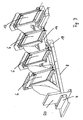
- FIG. 1 is a roof top 2 to see, which is composed essentially of a roof opening surrounding an upper rim 4 and thereon mounted lamellae 6.
- the slats 6 are connected to each other via a coupling rod 8, wherein the slats 6 are pivotable about a pivot axis by a movement of the coupling rod 8 in order to open or close them.
- Each of the fins 6 is connected to the coupling rod 8 via a hinge connection 10.
- the roof attachment 2 also has an edge-side lamella 12 whose axis of rotation is arranged outside the attachment ring 4.
- the edge-side slat 12 is operatively connected via a connecting rod 14 with other slats 6, in the illustrated embodiment, the connection to two other slats 6. If the slats 6 pivoted by a movement of the coupling rod 8, the pivotal movement of the slats 6 via the connecting rod 14 on the edge-side slat 12 transmitted. Even if the coupling rod 8 is operatively connected only to the slats 6, the connecting rod 14 transmits the pivoting movement to the edge-side slat 12, so that there is a same direction to the slats 6 pivotal movement.
- FIG. 2 the lamellae 6 and the edge-side lamella 12 are shown in a partially opened pivoting position.
- the spatial position of the coupling rod 8 has changed.
- the displacement movement of the coupling rod 8 has been transferred into a pivoting movement of the slats 6, so that in the position shown, the coupling rod 8, the partially open pivot position of the slats 6 results.
- the edge displacement of the coupling rod 8 indirectly via the connecting rod 14 and the edge-side plate 12 has been spent in a partially open pivot position.
- the connecting rod 14 is in the installation space between the coupling rod 8 and the slats 6 and is located in a parallel position to the coupling rod. 8
- the edge-side lamella 12 has on its underside a support tab 16 which is designed in its spatial position and peripheral contour so that it is supported in the illustrated pivot position on the part 18 which is connected to the coupling rod 8.
- the support tab 16 over the entire travel of the coupling rod 8 from the in FIG. 1 shown position to the in FIG. 2 shown position of the part 18 has been pushed up and the part 18 has issued with its slot-like recess a kind of backdrop for the pivoting movement of the edge-side sipe 12.
- FIG. 2 is further recognizable that by the displacement of the coupling rod 8 of the in FIG. 1 shown position in the FIG. 2 shown position the wind deflector 20 from the in FIG. 1 shown rest position in the in FIG. 2 shown position has been moved, in which the wind deflector 20 already slightly surmounted the upper edge of the top ring 4.
- FIG. 3 the lamellae 6 and the edge-side lamella 12 are shown in a fully pivoted-up position.
- the coupling rod 8 is opposite to in FIG. 2 shown position has been moved to the left in its final position.
- the support tab 16 is no longer supported on the part 18.
- the wind deflector 20 is in FIG. 3 mapped in a position which also corresponds to the end position for the wind deflector 20. In this position, the wind deflector 20 from a wind that could blow into the released from the left blade 6 opening without the wind deflector 20 and in this way could prevent the escape of hot air or smoke.
- FIG. 3 the lamellae 6 and the edge-side lamella 12 are shown in a fully pivoted-up position.
- the coupling rod 8 is opposite to in FIG. 2 shown position has been moved to the left in its final position.
- the support tab 16 is no longer supported on the part 18.
- the wind deflector 20 is in FIG. 3 mapped in a position which also corresponds to the end position for
- edge-side sipe 12 in the illustrated pivoting position does not obstruct the surface bounded by the top rim 4 with its material thickness.
- the roof attachment 2 in the exemplary embodiment has a total of four slats 6, 12, only three slats are in the opened pivoting position of the slats 6, 12 over area bounded by the top rim 4.
- FIG. 4 the blades 6, 12 are in a closed position from a different perspective than in FIG. 1 shown.
- the hinge connection of the wind deflector 20 to the coupling rod 8 can be seen. It can also be seen that the lamellae 6, 12 overlap at least partially in their closed position.
- FIG. 5 It can be seen that the wind deflector 20 is placed on a support ring 4 associated support surface and slides at a movement of the coupling rod 8 with its free end on the support surface in an opening movement of the slats 6, 12 upwards.
- the wind deflector 20 In the in FIG. 6 shown pivoting position, the wind deflector 20 is in a direction of Aufsatzkranz 4 almost vertical position. In this position, it is held by the coupling rod 8. In the case of a closing movement of the coupling rod 8, the wind deflector 20 would slide down again on the support surface until it has completely disappeared in a complete closing of the slats 6, 12 again in the space of the top ring 4.
Landscapes
- Engineering & Computer Science (AREA)
- Architecture (AREA)
- Civil Engineering (AREA)
- Structural Engineering (AREA)
- Chemical & Material Sciences (AREA)
- Combustion & Propulsion (AREA)
- Mechanical Engineering (AREA)
- General Engineering & Computer Science (AREA)
- Physics & Mathematics (AREA)
- Electromagnetism (AREA)
- Specific Sealing Or Ventilating Devices For Doors And Windows (AREA)
- Tents Or Canopies (AREA)
Priority Applications (1)
| Application Number | Priority Date | Filing Date | Title |
|---|---|---|---|
| PL09010890T PL2159339T3 (pl) | 2008-09-02 | 2009-08-26 | Wywietrznik dachowy z wychylnymi płytkami |
Applications Claiming Priority (1)
| Application Number | Priority Date | Filing Date | Title |
|---|---|---|---|
| DE102008045375A DE102008045375B4 (de) | 2008-09-02 | 2008-09-02 | Dachaufsatz mit schwenkbaren Lamellen |
Publications (3)
| Publication Number | Publication Date |
|---|---|
| EP2159339A2 EP2159339A2 (de) | 2010-03-03 |
| EP2159339A3 EP2159339A3 (de) | 2011-01-26 |
| EP2159339B1 true EP2159339B1 (de) | 2012-05-30 |
Family
ID=41352365
Family Applications (1)
| Application Number | Title | Priority Date | Filing Date |
|---|---|---|---|
| EP09010890A Active EP2159339B1 (de) | 2008-09-02 | 2009-08-26 | Dachaufsatz mit schwenkbaren Lamellen |
Country Status (4)
| Country | Link |
|---|---|
| EP (1) | EP2159339B1 (es) |
| DE (1) | DE102008045375B4 (es) |
| ES (1) | ES2387936T3 (es) |
| PL (1) | PL2159339T3 (es) |
Families Citing this family (8)
| Publication number | Priority date | Publication date | Assignee | Title |
|---|---|---|---|---|
| DE102011000163A1 (de) | 2011-01-15 | 2012-07-19 | Essmann Gmbh | Dachaufsatz |
| DE202011109864U1 (de) | 2011-01-15 | 2012-05-18 | Essmann Gmbh | Dachaufsatz |
| GB2511053B (en) | 2013-02-20 | 2017-09-20 | Orangebox Ltd | A ceiling panel |
| DE102013109391A1 (de) * | 2013-08-29 | 2015-03-19 | Jürgen Grimmeisen | Lamellendach |
| BE1021848B1 (nl) * | 2013-10-31 | 2016-01-22 | Renson Sunprotection-Screens Nv | Lamellendak |
| FR3042532B1 (fr) * | 2015-10-16 | 2018-02-16 | Souchier-Boullet | Fenetre a lames |
| FR3047508A1 (fr) * | 2016-02-09 | 2017-08-11 | Souchier | Fenetre avec pare-vent |
| CN111472502A (zh) * | 2020-05-13 | 2020-07-31 | 福州台江筑途科技有限公司 | 一种多功能钢结构天窗设备 |
Family Cites Families (7)
| Publication number | Priority date | Publication date | Assignee | Title |
|---|---|---|---|---|
| NL7712560A (nl) * | 1977-11-15 | 1979-05-17 | Hubertus Gerardus Jacobus Peet | Dakventilatie-inrichting. |
| NL8000286A (nl) * | 1980-01-16 | 1981-08-17 | Hubertus Gerardus Jacobus Peet | Jalouzieventilator; lamel. |
| GB2207233A (en) * | 1987-05-29 | 1989-01-25 | Nuaire Ltd | Louvre ventilator smoke vents |
| NL8902653A (nl) * | 1989-10-26 | 1991-05-16 | Atmos B V | Ventilatie-inrichting. |
| DE9110964U1 (de) * | 1990-09-28 | 1991-10-31 | E.M.B. Metallbau und Brandschutztechnik GmbH, 4240 Emmerich | Lamellenlüfter für Gebäudedächer |
| DE20214244U1 (de) * | 2002-09-13 | 2002-12-05 | Zimmermann, Franz-Josef, 59872 Meschede | Lamellendach |
| DE202005019510U1 (de) * | 2005-12-14 | 2006-02-23 | Seele Gmbh & Co. Kg | Abzugsklappe mit beweglichem Windleitblech |
-
2008
- 2008-09-02 DE DE102008045375A patent/DE102008045375B4/de not_active Expired - Fee Related
-
2009
- 2009-08-26 ES ES09010890T patent/ES2387936T3/es active Active
- 2009-08-26 PL PL09010890T patent/PL2159339T3/pl unknown
- 2009-08-26 EP EP09010890A patent/EP2159339B1/de active Active
Also Published As
| Publication number | Publication date |
|---|---|
| DE102008045375B4 (de) | 2010-10-21 |
| DE102008045375A1 (de) | 2010-03-04 |
| EP2159339A3 (de) | 2011-01-26 |
| PL2159339T3 (pl) | 2012-10-31 |
| ES2387936T3 (es) | 2012-10-04 |
| EP2159339A2 (de) | 2010-03-03 |
Similar Documents
| Publication | Publication Date | Title |
|---|---|---|
| EP2159339B1 (de) | Dachaufsatz mit schwenkbaren Lamellen | |
| DE102012101175B4 (de) | Drosseleinrichtung für den Luftdurchsatz durch einen Lufteinlass | |
| EP0555757A1 (de) | Fahrzeughaube mit Scharnier | |
| EP2745664B1 (de) | Bodenwanne zum verbinden eines dachaufbau-kühlgerätes mit dem dach eines schaltschrankes | |
| EP2354698A2 (de) | Lüftungsgitter zum Einbau in eine Aussenwand | |
| DE202008017906U1 (de) | Leitflächenlüfter für ein Dach eines Gebäudes | |
| DE60223944T2 (de) | Gelenkkonstruktion | |
| DE102009059107B4 (de) | Gelenkanordnung zur Betätigung einer Klappe, insbesondere Entrauchungsklappe | |
| DE19830678C2 (de) | Gelenkanordnung zur Betätigung einer Klappe oder dergleichen | |
| DE202015000199U1 (de) | Flügelüberschlagslüfter mit schräg verschiebbarem Dichtungsschieber | |
| EP2614706B1 (de) | Firstkonstruktion | |
| DE2360285B2 (de) | Luftungs- und Druckentlastungsvorrichtung für Schaltanlagen | |
| EP3643849B1 (de) | Dach-, decken- oder fassadenöffnung | |
| DE2842727A1 (de) | Vorrichtung zur gesteuerten abgabe von zuluft in zu belueftende und/oder zu klimatisierende raeume | |
| DE3432631C2 (de) | Lüftungsfirst zur Verwendung bei einem Gebäudedach, insbesondere Stalldach | |
| EP2657613B1 (de) | Türe für Heizeinrichtung | |
| DE2801673C2 (de) | Verschlußklappe für einen Abzug, insbesondere für einen Kamin | |
| DE202011005195U1 (de) | Rauchabzugsvorrichtung | |
| DE2226974A1 (de) | Ventilator | |
| DE102005045963B3 (de) | Vorrichtung zum Öffnen und Schließen einer Abdeckung | |
| DE202010000641U1 (de) | Lamellenfenster | |
| DE10112060B4 (de) | Aggregatekasten, insbesondere für ein Fahrzeug | |
| DE8426219U1 (de) | Lüftungsfirst zur Verwendung bei einem an einem Gebäudedach, vorzugsweise Stalldach vorgesehenen Licht- und/oder Lüftungsschacht | |
| DE29517956U1 (de) | Kaminabdeckung | |
| DE8007000U1 (de) | Einbau-kochmulde fuer herde |
Legal Events
| Date | Code | Title | Description |
|---|---|---|---|
| PUAI | Public reference made under article 153(3) epc to a published international application that has entered the european phase |
Free format text: ORIGINAL CODE: 0009012 |
|
| AK | Designated contracting states |
Kind code of ref document: A2 Designated state(s): AT BE BG CH CY CZ DE DK EE ES FI FR GB GR HR HU IE IS IT LI LT LU LV MC MK MT NL NO PL PT RO SE SI SK SM TR |
|
| AX | Request for extension of the european patent |
Extension state: AL BA RS |
|
| RIN1 | Information on inventor provided before grant (corrected) |
Inventor name: WINDHAUSEN, MICHAEL |
|
| PUAL | Search report despatched |
Free format text: ORIGINAL CODE: 0009013 |
|
| AK | Designated contracting states |
Kind code of ref document: A3 Designated state(s): AT BE BG CH CY CZ DE DK EE ES FI FR GB GR HR HU IE IS IT LI LT LU LV MC MK MT NL NO PL PT RO SE SI SK SM TR |
|
| AX | Request for extension of the european patent |
Extension state: AL BA RS |
|
| 17P | Request for examination filed |
Effective date: 20110608 |
|
| RIC1 | Information provided on ipc code assigned before grant |
Ipc: F24F 7/02 20060101ALI20111005BHEP Ipc: E06B 7/086 20060101ALI20111005BHEP Ipc: E04D 13/035 20060101ALI20111005BHEP Ipc: E04B 7/16 20060101AFI20111005BHEP |
|
| GRAP | Despatch of communication of intention to grant a patent |
Free format text: ORIGINAL CODE: EPIDOSNIGR1 |
|
| GRAS | Grant fee paid |
Free format text: ORIGINAL CODE: EPIDOSNIGR3 |
|
| GRAA | (expected) grant |
Free format text: ORIGINAL CODE: 0009210 |
|
| AK | Designated contracting states |
Kind code of ref document: B1 Designated state(s): AT BE BG CH CY CZ DE DK EE ES FI FR GB GR HR HU IE IS IT LI LT LU LV MC MK MT NL NO PL PT RO SE SI SK SM TR |
|
| REG | Reference to a national code |
Ref country code: GB Ref legal event code: FG4D Free format text: NOT ENGLISH |
|
| REG | Reference to a national code |
Ref country code: CH Ref legal event code: EP |
|
| REG | Reference to a national code |
Ref country code: AT Ref legal event code: REF Ref document number: 560151 Country of ref document: AT Kind code of ref document: T Effective date: 20120615 |
|
| REG | Reference to a national code |
Ref country code: IE Ref legal event code: FG4D Free format text: LANGUAGE OF EP DOCUMENT: GERMAN |
|
| REG | Reference to a national code |
Ref country code: DE Ref legal event code: R096 Ref document number: 502009003647 Country of ref document: DE Effective date: 20120726 |
|
| REG | Reference to a national code |
Ref country code: CH Ref legal event code: NV Representative=s name: SCHNEIDER FELDMANN AG PATENT- UND MARKENANWAELTE |
|
| REG | Reference to a national code |
Ref country code: NL Ref legal event code: T3 |
|
| REG | Reference to a national code |
Ref country code: ES Ref legal event code: FG2A Ref document number: 2387936 Country of ref document: ES Kind code of ref document: T3 Effective date: 20121004 |
|
| REG | Reference to a national code |
Ref country code: LT Ref legal event code: MG4D Effective date: 20120530 |
|
| PG25 | Lapsed in a contracting state [announced via postgrant information from national office to epo] |
Ref country code: CY Free format text: LAPSE BECAUSE OF FAILURE TO SUBMIT A TRANSLATION OF THE DESCRIPTION OR TO PAY THE FEE WITHIN THE PRESCRIBED TIME-LIMIT Effective date: 20120530 Ref country code: NO Free format text: LAPSE BECAUSE OF FAILURE TO SUBMIT A TRANSLATION OF THE DESCRIPTION OR TO PAY THE FEE WITHIN THE PRESCRIBED TIME-LIMIT Effective date: 20120830 Ref country code: FI Free format text: LAPSE BECAUSE OF FAILURE TO SUBMIT A TRANSLATION OF THE DESCRIPTION OR TO PAY THE FEE WITHIN THE PRESCRIBED TIME-LIMIT Effective date: 20120530 Ref country code: SE Free format text: LAPSE BECAUSE OF FAILURE TO SUBMIT A TRANSLATION OF THE DESCRIPTION OR TO PAY THE FEE WITHIN THE PRESCRIBED TIME-LIMIT Effective date: 20120530 Ref country code: IS Free format text: LAPSE BECAUSE OF FAILURE TO SUBMIT A TRANSLATION OF THE DESCRIPTION OR TO PAY THE FEE WITHIN THE PRESCRIBED TIME-LIMIT Effective date: 20120930 Ref country code: LT Free format text: LAPSE BECAUSE OF FAILURE TO SUBMIT A TRANSLATION OF THE DESCRIPTION OR TO PAY THE FEE WITHIN THE PRESCRIBED TIME-LIMIT Effective date: 20120530 |
|
| REG | Reference to a national code |
Ref country code: PL Ref legal event code: T3 |
|
| REG | Reference to a national code |
Ref country code: SK Ref legal event code: T3 Ref document number: E 12280 Country of ref document: SK |
|
| PG25 | Lapsed in a contracting state [announced via postgrant information from national office to epo] |
Ref country code: HR Free format text: LAPSE BECAUSE OF FAILURE TO SUBMIT A TRANSLATION OF THE DESCRIPTION OR TO PAY THE FEE WITHIN THE PRESCRIBED TIME-LIMIT Effective date: 20120530 Ref country code: SI Free format text: LAPSE BECAUSE OF FAILURE TO SUBMIT A TRANSLATION OF THE DESCRIPTION OR TO PAY THE FEE WITHIN THE PRESCRIBED TIME-LIMIT Effective date: 20120530 Ref country code: LV Free format text: LAPSE BECAUSE OF FAILURE TO SUBMIT A TRANSLATION OF THE DESCRIPTION OR TO PAY THE FEE WITHIN THE PRESCRIBED TIME-LIMIT Effective date: 20120530 Ref country code: GR Free format text: LAPSE BECAUSE OF FAILURE TO SUBMIT A TRANSLATION OF THE DESCRIPTION OR TO PAY THE FEE WITHIN THE PRESCRIBED TIME-LIMIT Effective date: 20120831 |
|
| PG25 | Lapsed in a contracting state [announced via postgrant information from national office to epo] |
Ref country code: RO Free format text: LAPSE BECAUSE OF FAILURE TO SUBMIT A TRANSLATION OF THE DESCRIPTION OR TO PAY THE FEE WITHIN THE PRESCRIBED TIME-LIMIT Effective date: 20120530 Ref country code: EE Free format text: LAPSE BECAUSE OF FAILURE TO SUBMIT A TRANSLATION OF THE DESCRIPTION OR TO PAY THE FEE WITHIN THE PRESCRIBED TIME-LIMIT Effective date: 20120530 Ref country code: DK Free format text: LAPSE BECAUSE OF FAILURE TO SUBMIT A TRANSLATION OF THE DESCRIPTION OR TO PAY THE FEE WITHIN THE PRESCRIBED TIME-LIMIT Effective date: 20120530 |
|
| BERE | Be: lapsed |
Owner name: COLT INTERNATIONAL LICENSING LTD Effective date: 20120831 |
|
| PG25 | Lapsed in a contracting state [announced via postgrant information from national office to epo] |
Ref country code: IT Free format text: LAPSE BECAUSE OF FAILURE TO SUBMIT A TRANSLATION OF THE DESCRIPTION OR TO PAY THE FEE WITHIN THE PRESCRIBED TIME-LIMIT Effective date: 20120530 Ref country code: PT Free format text: LAPSE BECAUSE OF FAILURE TO SUBMIT A TRANSLATION OF THE DESCRIPTION OR TO PAY THE FEE WITHIN THE PRESCRIBED TIME-LIMIT Effective date: 20121001 |
|
| PG25 | Lapsed in a contracting state [announced via postgrant information from national office to epo] |
Ref country code: MC Free format text: LAPSE BECAUSE OF NON-PAYMENT OF DUE FEES Effective date: 20120831 |
|
| PLBE | No opposition filed within time limit |
Free format text: ORIGINAL CODE: 0009261 |
|
| STAA | Information on the status of an ep patent application or granted ep patent |
Free format text: STATUS: NO OPPOSITION FILED WITHIN TIME LIMIT |
|
| 26N | No opposition filed |
Effective date: 20130301 |
|
| REG | Reference to a national code |
Ref country code: IE Ref legal event code: MM4A |
|
| PG25 | Lapsed in a contracting state [announced via postgrant information from national office to epo] |
Ref country code: BE Free format text: LAPSE BECAUSE OF NON-PAYMENT OF DUE FEES Effective date: 20120831 |
|
| REG | Reference to a national code |
Ref country code: DE Ref legal event code: R097 Ref document number: 502009003647 Country of ref document: DE Effective date: 20130301 |
|
| PG25 | Lapsed in a contracting state [announced via postgrant information from national office to epo] |
Ref country code: BG Free format text: LAPSE BECAUSE OF FAILURE TO SUBMIT A TRANSLATION OF THE DESCRIPTION OR TO PAY THE FEE WITHIN THE PRESCRIBED TIME-LIMIT Effective date: 20120830 Ref country code: IE Free format text: LAPSE BECAUSE OF NON-PAYMENT OF DUE FEES Effective date: 20120826 |
|
| PG25 | Lapsed in a contracting state [announced via postgrant information from national office to epo] |
Ref country code: MT Free format text: LAPSE BECAUSE OF FAILURE TO SUBMIT A TRANSLATION OF THE DESCRIPTION OR TO PAY THE FEE WITHIN THE PRESCRIBED TIME-LIMIT Effective date: 20120530 |
|
| PG25 | Lapsed in a contracting state [announced via postgrant information from national office to epo] |
Ref country code: TR Free format text: LAPSE BECAUSE OF FAILURE TO SUBMIT A TRANSLATION OF THE DESCRIPTION OR TO PAY THE FEE WITHIN THE PRESCRIBED TIME-LIMIT Effective date: 20120530 |
|
| PG25 | Lapsed in a contracting state [announced via postgrant information from national office to epo] |
Ref country code: SM Free format text: LAPSE BECAUSE OF FAILURE TO SUBMIT A TRANSLATION OF THE DESCRIPTION OR TO PAY THE FEE WITHIN THE PRESCRIBED TIME-LIMIT Effective date: 20120530 Ref country code: LU Free format text: LAPSE BECAUSE OF NON-PAYMENT OF DUE FEES Effective date: 20120826 |
|
| PG25 | Lapsed in a contracting state [announced via postgrant information from national office to epo] |
Ref country code: HU Free format text: LAPSE BECAUSE OF FAILURE TO SUBMIT A TRANSLATION OF THE DESCRIPTION OR TO PAY THE FEE WITHIN THE PRESCRIBED TIME-LIMIT Effective date: 20090826 |
|
| PG25 | Lapsed in a contracting state [announced via postgrant information from national office to epo] |
Ref country code: MK Free format text: LAPSE BECAUSE OF FAILURE TO SUBMIT A TRANSLATION OF THE DESCRIPTION OR TO PAY THE FEE WITHIN THE PRESCRIBED TIME-LIMIT Effective date: 20120530 |
|
| REG | Reference to a national code |
Ref country code: FR Ref legal event code: PLFP Year of fee payment: 8 |
|
| REG | Reference to a national code |
Ref country code: FR Ref legal event code: PLFP Year of fee payment: 9 |
|
| REG | Reference to a national code |
Ref country code: FR Ref legal event code: PLFP Year of fee payment: 10 |
|
| REG | Reference to a national code |
Ref country code: CH Ref legal event code: PFA Owner name: COLT INTERNATIONAL LICENSING LIMITED, GB Free format text: FORMER OWNER: COLT INTERNATIONAL LICENSING LIMITED, GB |
|
| PGFP | Annual fee paid to national office [announced via postgrant information from national office to epo] |
Ref country code: NL Payment date: 20230825 Year of fee payment: 15 |
|
| PGFP | Annual fee paid to national office [announced via postgrant information from national office to epo] |
Ref country code: GB Payment date: 20230707 Year of fee payment: 15 Ref country code: ES Payment date: 20230914 Year of fee payment: 15 Ref country code: CZ Payment date: 20230828 Year of fee payment: 15 Ref country code: CH Payment date: 20230902 Year of fee payment: 15 Ref country code: AT Payment date: 20230818 Year of fee payment: 15 |
|
| PGFP | Annual fee paid to national office [announced via postgrant information from national office to epo] |
Ref country code: SK Payment date: 20230808 Year of fee payment: 15 Ref country code: PL Payment date: 20230810 Year of fee payment: 15 Ref country code: DE Payment date: 20230612 Year of fee payment: 15 |
|
| PGFP | Annual fee paid to national office [announced via postgrant information from national office to epo] |
Ref country code: FR Payment date: 20240614 Year of fee payment: 16 |