EP2159177B1 - Procédé et dispositif de fabrication de piles de feuilles imprimées - Google Patents
Procédé et dispositif de fabrication de piles de feuilles imprimées Download PDFInfo
- Publication number
- EP2159177B1 EP2159177B1 EP08405208A EP08405208A EP2159177B1 EP 2159177 B1 EP2159177 B1 EP 2159177B1 EP 08405208 A EP08405208 A EP 08405208A EP 08405208 A EP08405208 A EP 08405208A EP 2159177 B1 EP2159177 B1 EP 2159177B1
- Authority
- EP
- European Patent Office
- Prior art keywords
- stack
- pressing
- support
- carriage
- supporting
- Prior art date
- Legal status (The legal status is an assumption and is not a legal conclusion. Google has not performed a legal analysis and makes no representation as to the accuracy of the status listed.)
- Not-in-force
Links
Images


Classifications
-
- B—PERFORMING OPERATIONS; TRANSPORTING
- B65—CONVEYING; PACKING; STORING; HANDLING THIN OR FILAMENTARY MATERIAL
- B65H—HANDLING THIN OR FILAMENTARY MATERIAL, e.g. SHEETS, WEBS, CABLES
- B65H31/00—Pile receivers
- B65H31/04—Pile receivers with movable end support arranged to recede as pile accumulates
- B65H31/06—Pile receivers with movable end support arranged to recede as pile accumulates the articles being piled on edge
-
- B—PERFORMING OPERATIONS; TRANSPORTING
- B65—CONVEYING; PACKING; STORING; HANDLING THIN OR FILAMENTARY MATERIAL
- B65B—MACHINES, APPARATUS OR DEVICES FOR, OR METHODS OF, PACKAGING ARTICLES OR MATERIALS; UNPACKING
- B65B27/00—Bundling particular articles presenting special problems using string, wire, or narrow tape or band; Baling fibrous material, e.g. peat, not otherwise provided for
- B65B27/08—Bundling paper sheets, envelopes, bags, newspapers, or other thin flat articles
-
- B—PERFORMING OPERATIONS; TRANSPORTING
- B65—CONVEYING; PACKING; STORING; HANDLING THIN OR FILAMENTARY MATERIAL
- B65H—HANDLING THIN OR FILAMENTARY MATERIAL, e.g. SHEETS, WEBS, CABLES
- B65H33/00—Forming counted batches in delivery pile or stream of articles
- B65H33/02—Forming counted batches in delivery pile or stream of articles by moving a blade or like member into the pile
-
- B—PERFORMING OPERATIONS; TRANSPORTING
- B65—CONVEYING; PACKING; STORING; HANDLING THIN OR FILAMENTARY MATERIAL
- B65H—HANDLING THIN OR FILAMENTARY MATERIAL, e.g. SHEETS, WEBS, CABLES
- B65H2301/00—Handling processes for sheets or webs
- B65H2301/40—Type of handling process
- B65H2301/42—Piling, depiling, handling piles
- B65H2301/421—Forming a pile
- B65H2301/4214—Forming a pile of articles on edge
- B65H2301/42146—Forming a pile of articles on edge by introducing articles from above
-
- B—PERFORMING OPERATIONS; TRANSPORTING
- B65—CONVEYING; PACKING; STORING; HANDLING THIN OR FILAMENTARY MATERIAL
- B65H—HANDLING THIN OR FILAMENTARY MATERIAL, e.g. SHEETS, WEBS, CABLES
- B65H2301/00—Handling processes for sheets or webs
- B65H2301/40—Type of handling process
- B65H2301/42—Piling, depiling, handling piles
- B65H2301/422—Handling piles, sets or stacks of articles
- B65H2301/4223—Pressing piles
-
- B—PERFORMING OPERATIONS; TRANSPORTING
- B65—CONVEYING; PACKING; STORING; HANDLING THIN OR FILAMENTARY MATERIAL
- B65H—HANDLING THIN OR FILAMENTARY MATERIAL, e.g. SHEETS, WEBS, CABLES
- B65H2301/00—Handling processes for sheets or webs
- B65H2301/40—Type of handling process
- B65H2301/42—Piling, depiling, handling piles
- B65H2301/426—Forming batches
- B65H2301/4263—Feeding end plate or end sheet before formation or after completion of a pile
Definitions
- the invention relates to a device for producing stacks of continuously fed to a horizontally extending stack support, vertically aligned printing sheet, with a printing sheet of the stack support feeding conveyor and a for forming a stack in a forming stack engaging support device, with which a forming Stack sustainable and a pressing device can be handed over, which has a first and a second compacting carriage, between which an educated stack can be pressed off, wherein the first compacting carriage with a back side facing away from the conveying device can be applied to theproofpressenden stack.
- the sheets are conveyed in a shingled stream vertically from top to bottom on a horizontal stack support.
- the forming stack or rod is supported on both sides of the stack by a support device. If the stack or the rod has reached the desired length, it is transferred from the support device to two press carriages. The stack is pressed and finally strapped with these two compacts.
- strapping a stack is meant any process in which the squeezed stack is stabilized for further transport.
- the strapped stack is sent for further processing, for example, handed over to a feeder.
- a next stack is simultaneously formed on the stack support.
- a device which, in order to shorten the cycle time, has a supporting device which has a third lifting element which is assigned to the front end of the stack in the direction of stacking conveying.
- the third support element is to be driven drivable independently of a first and second support element along the stack support, whereby more freedom of action and a higher production capacity to be achieved.
- the supporting device also serves as a separating device for separating a subsequent stack.
- a disadvantage is the comparatively complex structure of the support or separation device.
- the invention is based on the object to provide a device which also allows a shorter cycle time, but is less expensive.
- the object is achieved according to claim 1 characterized
- the first compacting carriage has supporting elements with which a forming stack can be supported on a stacking side facing away from the conveying device.
- the first compacting carriage has two pressing members, each of which has a rear side facing away from the conveying device for pressing off a stack formed on the stacking support.
- These pressing members are preferably arranged at a distance from each other and movable transversely to the stack conveying direction. The distance between the pressing members can be easily adapted to the format of the sheet or to the width of the stack.
- the support elements are arranged at least on one of the two pressing members, on which the conveyor device facing side.
- the support elements can thus be adjusted together with the pressing members transversely to the staple conveying direction.
- a support element is arranged on each pressing element.
- the support elements are preferably movable from an inner to an outer position. In the outer position they do not restrict the space between the pressing organs. It is therefore also possible to form comparatively wide stacks, for example double-use stacks, i. from two cohesively produced, identical products, which are only separated in a subsequent process step.
- the support members may be formed, for example, as brackets, plates or the like and pivoted, moved or otherwise moved between the two positions. Your drive is done for example with a control cylinder, but other drive means are conceivable.
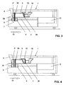
- the device 1 has according to FIG. 1 a machine frame 2, which has a horizontally extending stack support 3.
- the stack support 3 are printed with a conveying device 4 6 ( FIG. 8 ) fed from a scale flow in approximately vertical direction from above.
- Such conveyor belts 4 for shingled streams which consist for example of two belts, are well known to the person skilled in the art and therefore need not be further explained here.
- the stack 5 is supported on the stack side 38 away from the conveyor 4 by a first support and separation element 8 of a support device 7.
- the support device 7 has a second supporting and separating element 9, with which the forming stack 5 in a conventional manner a previously introduced into the stack support 3, the first end plate 10 is supplied.
- the stack side 38 moves in a stack conveying direction 13 to the right. Accordingly, the support device 7 is at least temporarily also moved to the right when forming the stack 5.
- the device 1 also has a pressing device 29 with a first pressing carriage 15 and a second pressing carriage 16.
- the two pressing carriages 15 and 16 are movable both in and against the stack conveying direction 13. Between the two pressing carriages 15 and 16, a stack 5 formed in the manner described above can be pressed in a subsequent method step, ie essentially the compressed air cushion located between the individual printing sheets 6 and the stack 5 thus compressed.
- a second end plate 11th created, which consist for example of wood.
- the arrows 32 shown on the right side of FIG. 1 indicate the directions of the forces with which a previously formed stack 5 is pressed into a stack 5 '.
- a strapping device 12 arranged in this region of the device 1 and known to the person skilled in the art serves for strapping the pressed-out stack 5 '.
- the way in which the stack 5 'is strapped and thus stabilized is not essential to the invention; it is merely a question of being able to transport the pressed-out stack 5' safely to a subsequent further processing.
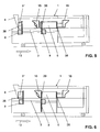
- the first pressing carriage 15, which moves in the direction of the forming stack 5 passes through the second, for example, fork-shaped supporting and separating element 9 and thus takes over the support of the stack 5 on the stack side 38.
- the second supporting and separating element 9 Since the stack 5 is now supported by the first press carriage 15, the second supporting and separating element 9 is also free. It is therefore first moved down and to the left and passes together with the first support and separating element 8 in the FIG. 3 shown position.
- the two supporting and separating elements 8 and 9 drive from below into the stack 5 and thereby separate a subsequent, forming stack 5 "from the stack 5.
- This separation of a stack 5" is the Skilled in the art.
- the prior art is on the EP-A-0 623 542 .
- the second supporting and separating element 9 of the support device 7 is thereby free and in the in FIG. 6 Lower position shown driven.
- the two press carriages 15 and 16 press the stack 5 and drive it into the in FIG. 7 shown position in which he is strapped.
- the second separating element 9 is again in the in FIG. 1 shown position. The described procedure can now be repeated with the subsequent stack 5 ".
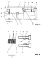
- FIGS. 8 to 18 show the procedures in the FIGS. 8 to 18 shown in plan view of parts of the device 1. From the first press carriage 15 are in FIG. 8 only two spaced apart pressing members 18 are shown, which may be formed substantially the same and extending in the stack conveying direction 13. Each pressing member 18 has a pressing jaw 21 (FIG. Fig. 19, 20 ), on which a movable support member 30 is arranged.
- FIG. 9 the forming stack 5 is supported by the first supporting and separating element 8. Thereafter, the first end plate 10 is moved with the second supporting and separating element 9, not shown here, against the stack 5, so that the first supporting and separating element 8 can be removed.
- FIG. 10 shows the device 1 in a subsequent method step in which the stack 5 is supported on the stack side 38 away from the conveyor device 4 by the first compacting carriage 15. For this purpose, the two support elements 30 are respectively applied to the first end plate 10.
- the stack 5 is here partly in a gap 33 between the two pressing members 18th
- FIG. 11 shows the movement of the second press carriage 16 towards the stack 5.
- the second press carriage 16 moves with two jaws 34 in the intermediate space 33 of the two pressing members 18 in the FIG. 12 shown position.
- the two jaws 34 now abut against the first end plate 10 with a front end and support it, whereby the stack 5 on the stack side 38 is now supported by the second pressing carriage 16.
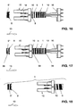
- the two pressing members 18 of the first press carriage 15 are moved apart transversely to the stack conveying direction 13.
- the two support members 30 in their in FIG. 13 shown retracted position moves.
- the movement may be a pivoting movement, a sliding movement or some other movement.
- the support members 30 do not restrict the gap 33 between the pressing members 18 in this retracted position.
- the gap 33 is thus free for the passage of the stack 5 in the conveying direction 13, wherein the stack 5 could also be substantially wider than in FIG FIG. 13 shown.
- FIGS. 14 and 15 show the movement of the previously separated by the supporting and separating elements 8, 9 from the stack 5 "stack 5 in the stack conveying direction 13, ie in the direction of the strapping 12.
- the stack 5 is doing on the stack side 39 of the second support and separating element 9 and is supported on the stacking side 38 by the second pressing carriage 16.
- the supporting and separating element 8 supports the forming stack 5 ".
- the FIGS. 16 and 17 show the subsequent movement of the first press carriage 15 in a supporting position in which this rests on the stack side 39, so that the second supporting and separating element 9 can be moved downwards away.
- the the FIG. 7 appropriate FIG. 18 finally shows the stack 5 in the region of the strapping device 12.
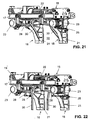
- the first press carriage 15 has a frame 17 to which four guide rollers 19 are fastened, on which the first press carriage 15 can be moved on rails, not shown here.
- a transversely extending axis 26 is fixed to the frame 17, on which the two pressing members 18 are mounted, each with a bearing 27 slidably.
- the pressing members 18 may each with a motor 23 and an endless drive member 31 for changing their in FIG. 19 shown distance 35 are moved on the axis 26.
- the distance 35 between the pressing members 18 can thus be reduced or increased.
- Width stack 5 are, for example, those from double benefits.
- FIG. 21 On the frame 17, another motor 22 is attached ( FIG. 21 ), which serves to apply the required pressing force when pressing a stack 5.
- the motor 22 acts via two gears 37 ( FIG. 19 ) on racks, not shown here.
- Cables 20 are used to provide electrical power to the motor 22.
- pneumatic and electrical connections and such are provided for a control device not shown here.
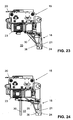
- each have a support member 30 is arranged, which is preferably rod-shaped or bow-shaped.
- the support elements 30 are each at an upper end via a linkage 28 (FIG. FIG. 22 ) pivotally mounted on a pressing jaw 21.
- Each support member 30 is connected via the linkage 28 with a pneumatic actuating cylinder 25 which is fixed to the corresponding pressing jaw 21.
- the control device not shown here.
- the support elements 30 are arranged behind the pressing jaws 21, so that they do not restrict the gap 33 and the maximum width for the passage of the stack 5 is available. Also comparatively wide stack 5 can be passed through the first press carriage 15 without collision.
- the support members 30 are located on one of the conveyor 4 facing side 36 of the pressing jaws 21 and thus the first press carriage 15. The back 24 of the pressing jaws 21 forms a surface on which a stack 5 is pressed.
- the support members 30 are here downwardly directed rod-shaped bracket. However, they can also be plate-shaped and mounted laterally displaceable. In principle, the support elements 30 can also be designed as non-movable surfaces of the conveyor device 4 facing side 36 of the pressing jaws 21. Essential is such a design of the support elements 30, with which they can take over a support function in a stack forming 5, 5 "as long as the second pressing carriage 16 is available. The support elements 30 can be realized with a comparatively small design effort, so that there are no significantly higher production costs, nevertheless the cycle time can be substantially reduced.
Claims (8)
- Dispositif de production de piles constituées par des feuillets d'impression (6) mutuellement alignés dans le sens vertical et délivrés, en continu, à un support (3) desdites piles qui s'étend dans le sens horizontal, comprenant un dispositif de convoyage (4) délivrant lesdits feuillets d'impression (6) audit support (3) des piles, et un dispositif de soutien (7) qui s'engage dans une pile (5) en formation, en vue de former une pile (5), et par lequel une pile (5) en formation peut être soutenu et transférée à un dispositif de pressage (29) comprenant un premier chariot de compression (15) et un second chariot de compression (16) entre lesquels une pile formée (5) peut être pressée, ledit premier chariot de compression (15) pouvant être plaqué, contre ladite pile (5) à presser, par une face postérieure (24) pointant à l'opposé dudit dispositif de convoyage (4), caractérisé par le fait que le premier chariot de compression (15) présente des éléments d'appui (30) contre lesquels une pile (5), en formation, peut prendre appui par une face (38) de ladite pile qui est tournée à l'opposé du dispositif de convoyage (4).
- Dispositif selon la revendication 1, caractérisé par le fait que le premier chariot de compression (15) comporte au moins un et, de préférence, deux éléments d'appui (30) mobiles.
- Dispositif selon la revendication 2, caractérisé par le fait que l'élément d'appui (30), à présence minimale, est mobile entre des positions intérieure et extérieure.
- Dispositif selon la revendication 3, caractérisé par le fait qu'au moins deux éléments d'appui (30) sont mobiles entre les positions intérieure et extérieure.
- Dispositif selon la revendication 2 ou 3, caractérisé par le fait que l'élément d'appui (30) à présence minimale est un étrier pivotant.
- Dispositif selon l'une des revendications 1 à 5, caractérisé par le fait que le premier chariot de compression (15) présente deux organes presseurs (18) montés mobiles, dans le sens transversal, par rapport à une direction (13) de convoyage des piles.
- Dispositif selon la revendication 6, caractérisé par le fait que l'élément d'appui (30), à présence minimale, est implanté sur l'un des deux organes presseurs (18)
- Dispositif selon l'une des revendications 1 à 7, caractérisé par le fait que les éléments d'appui (30) sont implantes sur une face (36) du premier chariot de compression (15) qui est tournée vers le dispositif de convoyage (4).
Priority Applications (5)
| Application Number | Priority Date | Filing Date | Title |
|---|---|---|---|
| AT08405208T ATE532729T1 (de) | 2008-08-29 | 2008-08-29 | Verfahren und vorrichtung zum herstellen von aus druckbogen bestehenden stapeln |
| EP08405208A EP2159177B1 (fr) | 2008-08-29 | 2008-08-29 | Procédé et dispositif de fabrication de piles de feuilles imprimées |
| JP2009196171A JP5436098B2 (ja) | 2008-08-29 | 2009-08-27 | 印刷紙から成る集積体を形成するための方法及び装置 |
| US12/549,660 US8376346B2 (en) | 2008-08-29 | 2009-08-28 | Device and method for producing stacks composed of printed sheets |
| CN200910170614.3A CN101659328B (zh) | 2008-08-29 | 2009-08-28 | 用于制造由印张构成的堆垛的方法和装置 |
Applications Claiming Priority (1)
| Application Number | Priority Date | Filing Date | Title |
|---|---|---|---|
| EP08405208A EP2159177B1 (fr) | 2008-08-29 | 2008-08-29 | Procédé et dispositif de fabrication de piles de feuilles imprimées |
Publications (2)
| Publication Number | Publication Date |
|---|---|
| EP2159177A1 EP2159177A1 (fr) | 2010-03-03 |
| EP2159177B1 true EP2159177B1 (fr) | 2011-11-09 |
Family
ID=40348840
Family Applications (1)
| Application Number | Title | Priority Date | Filing Date |
|---|---|---|---|
| EP08405208A Not-in-force EP2159177B1 (fr) | 2008-08-29 | 2008-08-29 | Procédé et dispositif de fabrication de piles de feuilles imprimées |
Country Status (5)
| Country | Link |
|---|---|
| US (1) | US8376346B2 (fr) |
| EP (1) | EP2159177B1 (fr) |
| JP (1) | JP5436098B2 (fr) |
| CN (1) | CN101659328B (fr) |
| AT (1) | ATE532729T1 (fr) |
Families Citing this family (5)
| Publication number | Priority date | Publication date | Assignee | Title |
|---|---|---|---|---|
| FR2983464B1 (fr) | 2011-12-05 | 2014-06-27 | Solystic | Dispositif d'empilage pour objets plats empiles sur chant et machine de tri postal |
| CN102530290A (zh) * | 2011-12-22 | 2012-07-04 | 上海烟草集团有限责任公司 | 自动化物流系统件烟组入库方法 |
| EP2695741B1 (fr) * | 2012-08-09 | 2015-03-04 | Müller Martini Holding AG | Machine de coudre |
| EP2778105B1 (fr) * | 2013-03-11 | 2016-10-26 | Wincor Nixdorf International GmbH | Dispositif et procédé de remplissage d'un récipient de transport avec des documents de valeur |
| CN113928903A (zh) * | 2021-10-18 | 2022-01-14 | 东莞市浩信精密机械有限公司 | 一种用于捆书机的不停机分纸机构 |
Family Cites Families (12)
| Publication number | Priority date | Publication date | Assignee | Title |
|---|---|---|---|---|
| CH663397A5 (de) * | 1984-05-11 | 1987-12-15 | Grapha Holding Ag | Stapeleinrichtung fuer druckbogen. |
| DE4117434A1 (de) * | 1991-05-28 | 1992-12-03 | Winkler Duennebier Kg Masch | Verfahren und vorrichtung zum stapeln |
| DE4202540A1 (de) | 1992-01-30 | 1993-08-05 | Giebeler Gmbh & Co Kg Robert | Verfahren und vorrichtung zur herstellung definierter stapel gefalzter oder ungefalzter blaetter oder blattfoermiger gegenstaende |
| JP4318322B2 (ja) | 1993-05-07 | 2009-08-19 | グラプハ−ホルディング・アクチエンゲゼルシヤフト | 並列して起立している刷紙に対して垂直方向で指向して堆積体を形成するための装置 |
| JP3443172B2 (ja) * | 1994-06-22 | 2003-09-02 | 大日本印刷株式会社 | 刷本集積装置 |
| EP0872443B1 (fr) | 1997-03-18 | 2002-12-11 | Grapha-Holding Ag | Dispositif pour former une pile partielle s'étandant perpendiculèrement aux feuilles imprimées rangées sur la tranche et une à côté de l'autre |
| FR2777876B1 (fr) * | 1998-04-24 | 2000-06-30 | Realisations Etudes Et Commerc | Dispositif d'empilage et de transfert de cahiers imprimes sous forme de cartouches |
| JP2000118511A (ja) * | 1998-08-13 | 2000-04-25 | Gunze Ltd | 刷本の結束装置 |
| EP1523443B1 (fr) * | 2002-07-19 | 2008-12-17 | Ferag AG | Procede et dispositif pour constituer des piles horizontales (barres) de produits d'imprimerie et pour les cercler |
| EP1405809B1 (fr) | 2002-10-02 | 2009-07-01 | Müller Martini Holding AG | Dispositif pour former des colis de produits empilés |
| EP1911711B1 (fr) * | 2005-08-05 | 2012-06-06 | Glory Ltd. | Bac de réception/alimentation de feuilles |
| EP1816098B1 (fr) * | 2006-02-02 | 2010-03-31 | Müller Martini Holding AG | Procédé et dispositif pour former des piles |
-
2008
- 2008-08-29 AT AT08405208T patent/ATE532729T1/de active
- 2008-08-29 EP EP08405208A patent/EP2159177B1/fr not_active Not-in-force
-
2009
- 2009-08-27 JP JP2009196171A patent/JP5436098B2/ja not_active Expired - Fee Related
- 2009-08-28 US US12/549,660 patent/US8376346B2/en not_active Expired - Fee Related
- 2009-08-28 CN CN200910170614.3A patent/CN101659328B/zh not_active Expired - Fee Related
Also Published As
| Publication number | Publication date |
|---|---|
| EP2159177A1 (fr) | 2010-03-03 |
| JP2010052946A (ja) | 2010-03-11 |
| ATE532729T1 (de) | 2011-11-15 |
| JP5436098B2 (ja) | 2014-03-05 |
| US8376346B2 (en) | 2013-02-19 |
| CN101659328A (zh) | 2010-03-03 |
| CN101659328B (zh) | 2014-03-05 |
| US20100050572A1 (en) | 2010-03-04 |
Similar Documents
| Publication | Publication Date | Title |
|---|---|---|
| EP0847949B1 (fr) | Dispositif pour empiler un chant de feuilles imprimées | |
| EP2072430A1 (fr) | Dispositif de saisie de paquet pour un dispositif de palettisation et procédé de palettisation de paquets | |
| EP2159177B1 (fr) | Procédé et dispositif de fabrication de piles de feuilles imprimées | |
| DE3836214C2 (fr) | ||
| EP2457858A1 (fr) | Dispositif et méthode pour la formation de paquets de produits imprimés | |
| DE3006229C2 (de) | Anlage zum Sortieren und Ablegen von Blätterstapeln | |
| DE2716806A1 (de) | Vorrichtung zum stapeln von flachmaterialstuecken | |
| DE2547149B2 (de) | Stapelvorrichtung zur Beschickung einer Etagenpresse | |
| DE3540203C2 (de) | Vorrichtung zum Fördern von Papierstapeln | |
| DE2508745C2 (de) | Vorrichtung zum Aufstauen vereinzelt mittels einer Transportvorrichtung zugeförderter Papierbögen zu Stapeln und zum Weitertransportieren dieser Stapel | |
| EP1405809B1 (fr) | Dispositif pour former des colis de produits empilés | |
| DE102007013382A1 (de) | Verfahren zum Herstellen eines Pressballens und Vorrichtung zum Herstellen von Pressballen | |
| EP2498983B1 (fr) | Dispositif et procédé pour la formation de piles de sachets | |
| EP0597387A1 (fr) | Presse avec dispositif de transfert de tôles | |
| EP2628591B1 (fr) | Presse destinée à la fabrication de balles compactées | |
| EP2138439B1 (fr) | Dispositif d'empilement de produits plats, notamment de produits d'impression | |
| EP1523443A1 (fr) | Procede et dispositif pour constituer des piles horizontales (barres) de produits d'imprimerie et pour les cercler | |
| EP1464602B1 (fr) | Dispositif pour former un courant d'objects plats se chevauchant | |
| EP0958217A1 (fr) | Dispositif changeur de piles | |
| EP1857182A2 (fr) | Procédé de transfert du début d'une bande de film ou d'une matrice de film restant d'une machine de thermoformage à un broyeur déchiqueteur et dispositif de transfert | |
| EP2192067B1 (fr) | Dispositif d'empilement pour produits d'impression | |
| EP0810174B1 (fr) | Dispositif pour l'empilage vertical de produits imprimés | |
| DE4406337C2 (de) | Vorrichtung zum Verschweißen der Adern von Litzen, insbesondere Kupferlitzen | |
| DE202017103053U1 (de) | Vorpresse und System zum kontinuierlichen Herstellen von Werkstoffplatten und Transportvorrichtung zum Aufnehmen des Pressenbandes | |
| EP2316767B1 (fr) | Dispositif et procédé de fabrication de piles de produits d'impression |
Legal Events
| Date | Code | Title | Description |
|---|---|---|---|
| PUAI | Public reference made under article 153(3) epc to a published international application that has entered the european phase |
Free format text: ORIGINAL CODE: 0009012 |
|
| AK | Designated contracting states |
Kind code of ref document: A1 Designated state(s): AT BE BG CH CY CZ DE DK EE ES FI FR GB GR HR HU IE IS IT LI LT LU LV MC MT NL NO PL PT RO SE SI SK TR |
|
| AX | Request for extension of the european patent |
Extension state: AL BA MK RS |
|
| 17P | Request for examination filed |
Effective date: 20100614 |
|
| 17Q | First examination report despatched |
Effective date: 20100903 |
|
| AKX | Designation fees paid |
Designated state(s): AT BE BG CH CY CZ DE DK EE ES FI FR GB GR HR HU IE IS IT LI LT LU LV MC MT NL NO PL PT RO SE SI SK TR |
|
| RIC1 | Information provided on ipc code assigned before grant |
Ipc: B65B 27/08 20060101ALI20110329BHEP Ipc: B65H 31/06 20060101AFI20110329BHEP Ipc: B65H 33/02 20060101ALI20110329BHEP |
|
| GRAP | Despatch of communication of intention to grant a patent |
Free format text: ORIGINAL CODE: EPIDOSNIGR1 |
|
| GRAS | Grant fee paid |
Free format text: ORIGINAL CODE: EPIDOSNIGR3 |
|
| GRAA | (expected) grant |
Free format text: ORIGINAL CODE: 0009210 |
|
| AK | Designated contracting states |
Kind code of ref document: B1 Designated state(s): AT BE BG CH CY CZ DE DK EE ES FI FR GB GR HR HU IE IS IT LI LT LU LV MC MT NL NO PL PT RO SE SI SK TR |
|
| REG | Reference to a national code |
Ref country code: GB Ref legal event code: FG4D Free format text: NOT ENGLISH |
|
| REG | Reference to a national code |
Ref country code: CH Ref legal event code: EP |
|
| REG | Reference to a national code |
Ref country code: IE Ref legal event code: FG4D Free format text: LANGUAGE OF EP DOCUMENT: GERMAN |
|
| REG | Reference to a national code |
Ref country code: DE Ref legal event code: R096 Ref document number: 502008005521 Country of ref document: DE Effective date: 20120216 |
|
| REG | Reference to a national code |
Ref country code: NL Ref legal event code: VDEP Effective date: 20111109 |
|
| LTIE | Lt: invalidation of european patent or patent extension |
Effective date: 20111109 |
|
| PG25 | Lapsed in a contracting state [announced via postgrant information from national office to epo] |
Ref country code: IS Free format text: LAPSE BECAUSE OF FAILURE TO SUBMIT A TRANSLATION OF THE DESCRIPTION OR TO PAY THE FEE WITHIN THE PRESCRIBED TIME-LIMIT Effective date: 20120309 Ref country code: NO Free format text: LAPSE BECAUSE OF FAILURE TO SUBMIT A TRANSLATION OF THE DESCRIPTION OR TO PAY THE FEE WITHIN THE PRESCRIBED TIME-LIMIT Effective date: 20120209 Ref country code: LT Free format text: LAPSE BECAUSE OF FAILURE TO SUBMIT A TRANSLATION OF THE DESCRIPTION OR TO PAY THE FEE WITHIN THE PRESCRIBED TIME-LIMIT Effective date: 20111109 |
|
| PG25 | Lapsed in a contracting state [announced via postgrant information from national office to epo] |
Ref country code: LV Free format text: LAPSE BECAUSE OF FAILURE TO SUBMIT A TRANSLATION OF THE DESCRIPTION OR TO PAY THE FEE WITHIN THE PRESCRIBED TIME-LIMIT Effective date: 20111109 Ref country code: PL Free format text: LAPSE BECAUSE OF FAILURE TO SUBMIT A TRANSLATION OF THE DESCRIPTION OR TO PAY THE FEE WITHIN THE PRESCRIBED TIME-LIMIT Effective date: 20111109 Ref country code: GR Free format text: LAPSE BECAUSE OF FAILURE TO SUBMIT A TRANSLATION OF THE DESCRIPTION OR TO PAY THE FEE WITHIN THE PRESCRIBED TIME-LIMIT Effective date: 20120210 Ref country code: PT Free format text: LAPSE BECAUSE OF FAILURE TO SUBMIT A TRANSLATION OF THE DESCRIPTION OR TO PAY THE FEE WITHIN THE PRESCRIBED TIME-LIMIT Effective date: 20120309 Ref country code: NL Free format text: LAPSE BECAUSE OF FAILURE TO SUBMIT A TRANSLATION OF THE DESCRIPTION OR TO PAY THE FEE WITHIN THE PRESCRIBED TIME-LIMIT Effective date: 20111109 Ref country code: SE Free format text: LAPSE BECAUSE OF FAILURE TO SUBMIT A TRANSLATION OF THE DESCRIPTION OR TO PAY THE FEE WITHIN THE PRESCRIBED TIME-LIMIT Effective date: 20111109 Ref country code: SI Free format text: LAPSE BECAUSE OF FAILURE TO SUBMIT A TRANSLATION OF THE DESCRIPTION OR TO PAY THE FEE WITHIN THE PRESCRIBED TIME-LIMIT Effective date: 20111109 Ref country code: HR Free format text: LAPSE BECAUSE OF FAILURE TO SUBMIT A TRANSLATION OF THE DESCRIPTION OR TO PAY THE FEE WITHIN THE PRESCRIBED TIME-LIMIT Effective date: 20111109 |
|
| REG | Reference to a national code |
Ref country code: IE Ref legal event code: FD4D |
|
| PG25 | Lapsed in a contracting state [announced via postgrant information from national office to epo] |
Ref country code: CY Free format text: LAPSE BECAUSE OF FAILURE TO SUBMIT A TRANSLATION OF THE DESCRIPTION OR TO PAY THE FEE WITHIN THE PRESCRIBED TIME-LIMIT Effective date: 20111109 |
|
| PG25 | Lapsed in a contracting state [announced via postgrant information from national office to epo] |
Ref country code: BG Free format text: LAPSE BECAUSE OF FAILURE TO SUBMIT A TRANSLATION OF THE DESCRIPTION OR TO PAY THE FEE WITHIN THE PRESCRIBED TIME-LIMIT Effective date: 20120209 Ref country code: IE Free format text: LAPSE BECAUSE OF FAILURE TO SUBMIT A TRANSLATION OF THE DESCRIPTION OR TO PAY THE FEE WITHIN THE PRESCRIBED TIME-LIMIT Effective date: 20111109 Ref country code: EE Free format text: LAPSE BECAUSE OF FAILURE TO SUBMIT A TRANSLATION OF THE DESCRIPTION OR TO PAY THE FEE WITHIN THE PRESCRIBED TIME-LIMIT Effective date: 20111109 Ref country code: DK Free format text: LAPSE BECAUSE OF FAILURE TO SUBMIT A TRANSLATION OF THE DESCRIPTION OR TO PAY THE FEE WITHIN THE PRESCRIBED TIME-LIMIT Effective date: 20111109 Ref country code: SK Free format text: LAPSE BECAUSE OF FAILURE TO SUBMIT A TRANSLATION OF THE DESCRIPTION OR TO PAY THE FEE WITHIN THE PRESCRIBED TIME-LIMIT Effective date: 20111109 Ref country code: CZ Free format text: LAPSE BECAUSE OF FAILURE TO SUBMIT A TRANSLATION OF THE DESCRIPTION OR TO PAY THE FEE WITHIN THE PRESCRIBED TIME-LIMIT Effective date: 20111109 |
|
| PG25 | Lapsed in a contracting state [announced via postgrant information from national office to epo] |
Ref country code: RO Free format text: LAPSE BECAUSE OF FAILURE TO SUBMIT A TRANSLATION OF THE DESCRIPTION OR TO PAY THE FEE WITHIN THE PRESCRIBED TIME-LIMIT Effective date: 20111109 |
|
| PLBE | No opposition filed within time limit |
Free format text: ORIGINAL CODE: 0009261 |
|
| STAA | Information on the status of an ep patent application or granted ep patent |
Free format text: STATUS: NO OPPOSITION FILED WITHIN TIME LIMIT |
|
| 26N | No opposition filed |
Effective date: 20120810 |
|
| REG | Reference to a national code |
Ref country code: DE Ref legal event code: R097 Ref document number: 502008005521 Country of ref document: DE Effective date: 20120810 |
|
| BERE | Be: lapsed |
Owner name: MULLER MARTINI HOLDING A.G. Effective date: 20120831 |
|
| PG25 | Lapsed in a contracting state [announced via postgrant information from national office to epo] |
Ref country code: MC Free format text: LAPSE BECAUSE OF NON-PAYMENT OF DUE FEES Effective date: 20120831 |
|
| GBPC | Gb: european patent ceased through non-payment of renewal fee |
Effective date: 20120829 |
|
| PG25 | Lapsed in a contracting state [announced via postgrant information from national office to epo] |
Ref country code: ES Free format text: LAPSE BECAUSE OF FAILURE TO SUBMIT A TRANSLATION OF THE DESCRIPTION OR TO PAY THE FEE WITHIN THE PRESCRIBED TIME-LIMIT Effective date: 20120220 |
|
| PG25 | Lapsed in a contracting state [announced via postgrant information from national office to epo] |
Ref country code: BE Free format text: LAPSE BECAUSE OF NON-PAYMENT OF DUE FEES Effective date: 20120831 |
|
| PG25 | Lapsed in a contracting state [announced via postgrant information from national office to epo] |
Ref country code: FI Free format text: LAPSE BECAUSE OF FAILURE TO SUBMIT A TRANSLATION OF THE DESCRIPTION OR TO PAY THE FEE WITHIN THE PRESCRIBED TIME-LIMIT Effective date: 20111109 |
|
| PG25 | Lapsed in a contracting state [announced via postgrant information from national office to epo] |
Ref country code: GB Free format text: LAPSE BECAUSE OF NON-PAYMENT OF DUE FEES Effective date: 20120829 |
|
| PG25 | Lapsed in a contracting state [announced via postgrant information from national office to epo] |
Ref country code: MT Free format text: LAPSE BECAUSE OF FAILURE TO SUBMIT A TRANSLATION OF THE DESCRIPTION OR TO PAY THE FEE WITHIN THE PRESCRIBED TIME-LIMIT Effective date: 20111109 |
|
| PG25 | Lapsed in a contracting state [announced via postgrant information from national office to epo] |
Ref country code: TR Free format text: LAPSE BECAUSE OF FAILURE TO SUBMIT A TRANSLATION OF THE DESCRIPTION OR TO PAY THE FEE WITHIN THE PRESCRIBED TIME-LIMIT Effective date: 20111109 |
|
| PG25 | Lapsed in a contracting state [announced via postgrant information from national office to epo] |
Ref country code: LU Free format text: LAPSE BECAUSE OF NON-PAYMENT OF DUE FEES Effective date: 20120829 |
|
| PG25 | Lapsed in a contracting state [announced via postgrant information from national office to epo] |
Ref country code: HU Free format text: LAPSE BECAUSE OF FAILURE TO SUBMIT A TRANSLATION OF THE DESCRIPTION OR TO PAY THE FEE WITHIN THE PRESCRIBED TIME-LIMIT Effective date: 20080829 |
|
| REG | Reference to a national code |
Ref country code: FR Ref legal event code: PLFP Year of fee payment: 8 |
|
| PGFP | Annual fee paid to national office [announced via postgrant information from national office to epo] |
Ref country code: DE Payment date: 20150812 Year of fee payment: 8 |
|
| PGFP | Annual fee paid to national office [announced via postgrant information from national office to epo] |
Ref country code: FR Payment date: 20150824 Year of fee payment: 8 Ref country code: AT Payment date: 20150824 Year of fee payment: 8 |
|
| PGFP | Annual fee paid to national office [announced via postgrant information from national office to epo] |
Ref country code: IT Payment date: 20150831 Year of fee payment: 8 |
|
| PGFP | Annual fee paid to national office [announced via postgrant information from national office to epo] |
Ref country code: CH Payment date: 20151120 Year of fee payment: 8 |
|
| REG | Reference to a national code |
Ref country code: DE Ref legal event code: R119 Ref document number: 502008005521 Country of ref document: DE |
|
| REG | Reference to a national code |
Ref country code: CH Ref legal event code: PL |
|
| REG | Reference to a national code |
Ref country code: AT Ref legal event code: MM01 Ref document number: 532729 Country of ref document: AT Kind code of ref document: T Effective date: 20160829 |
|
| PG25 | Lapsed in a contracting state [announced via postgrant information from national office to epo] |
Ref country code: LI Free format text: LAPSE BECAUSE OF NON-PAYMENT OF DUE FEES Effective date: 20160831 Ref country code: CH Free format text: LAPSE BECAUSE OF NON-PAYMENT OF DUE FEES Effective date: 20160831 |
|
| REG | Reference to a national code |
Ref country code: FR Ref legal event code: ST Effective date: 20170428 |
|
| PG25 | Lapsed in a contracting state [announced via postgrant information from national office to epo] |
Ref country code: AT Free format text: LAPSE BECAUSE OF NON-PAYMENT OF DUE FEES Effective date: 20160829 |
|
| PG25 | Lapsed in a contracting state [announced via postgrant information from national office to epo] |
Ref country code: FR Free format text: LAPSE BECAUSE OF NON-PAYMENT OF DUE FEES Effective date: 20160831 Ref country code: DE Free format text: LAPSE BECAUSE OF NON-PAYMENT OF DUE FEES Effective date: 20170301 |
|
| PG25 | Lapsed in a contracting state [announced via postgrant information from national office to epo] |
Ref country code: IT Free format text: LAPSE BECAUSE OF NON-PAYMENT OF DUE FEES Effective date: 20160829 |