EP2159177B1 - Device and method for producing piles of printed sheets - Google Patents
Device and method for producing piles of printed sheets Download PDFInfo
- Publication number
- EP2159177B1 EP2159177B1 EP08405208A EP08405208A EP2159177B1 EP 2159177 B1 EP2159177 B1 EP 2159177B1 EP 08405208 A EP08405208 A EP 08405208A EP 08405208 A EP08405208 A EP 08405208A EP 2159177 B1 EP2159177 B1 EP 2159177B1
- Authority
- EP
- European Patent Office
- Prior art keywords
- stack
- pressing
- support
- carriage
- supporting
- Prior art date
- Legal status (The legal status is an assumption and is not a legal conclusion. Google has not performed a legal analysis and makes no representation as to the accuracy of the status listed.)
- Not-in-force
Links
Images


Classifications
-
- B—PERFORMING OPERATIONS; TRANSPORTING
- B65—CONVEYING; PACKING; STORING; HANDLING THIN OR FILAMENTARY MATERIAL
- B65H—HANDLING THIN OR FILAMENTARY MATERIAL, e.g. SHEETS, WEBS, CABLES
- B65H31/00—Pile receivers
- B65H31/04—Pile receivers with movable end support arranged to recede as pile accumulates
- B65H31/06—Pile receivers with movable end support arranged to recede as pile accumulates the articles being piled on edge
-
- B—PERFORMING OPERATIONS; TRANSPORTING
- B65—CONVEYING; PACKING; STORING; HANDLING THIN OR FILAMENTARY MATERIAL
- B65B—MACHINES, APPARATUS OR DEVICES FOR, OR METHODS OF, PACKAGING ARTICLES OR MATERIALS; UNPACKING
- B65B27/00—Bundling particular articles presenting special problems using string, wire, or narrow tape or band; Baling fibrous material, e.g. peat, not otherwise provided for
- B65B27/08—Bundling paper sheets, envelopes, bags, newspapers, or other thin flat articles
-
- B—PERFORMING OPERATIONS; TRANSPORTING
- B65—CONVEYING; PACKING; STORING; HANDLING THIN OR FILAMENTARY MATERIAL
- B65H—HANDLING THIN OR FILAMENTARY MATERIAL, e.g. SHEETS, WEBS, CABLES
- B65H33/00—Forming counted batches in delivery pile or stream of articles
- B65H33/02—Forming counted batches in delivery pile or stream of articles by moving a blade or like member into the pile
-
- B—PERFORMING OPERATIONS; TRANSPORTING
- B65—CONVEYING; PACKING; STORING; HANDLING THIN OR FILAMENTARY MATERIAL
- B65H—HANDLING THIN OR FILAMENTARY MATERIAL, e.g. SHEETS, WEBS, CABLES
- B65H2301/00—Handling processes for sheets or webs
- B65H2301/40—Type of handling process
- B65H2301/42—Piling, depiling, handling piles
- B65H2301/421—Forming a pile
- B65H2301/4214—Forming a pile of articles on edge
- B65H2301/42146—Forming a pile of articles on edge by introducing articles from above
-
- B—PERFORMING OPERATIONS; TRANSPORTING
- B65—CONVEYING; PACKING; STORING; HANDLING THIN OR FILAMENTARY MATERIAL
- B65H—HANDLING THIN OR FILAMENTARY MATERIAL, e.g. SHEETS, WEBS, CABLES
- B65H2301/00—Handling processes for sheets or webs
- B65H2301/40—Type of handling process
- B65H2301/42—Piling, depiling, handling piles
- B65H2301/422—Handling piles, sets or stacks of articles
- B65H2301/4223—Pressing piles
-
- B—PERFORMING OPERATIONS; TRANSPORTING
- B65—CONVEYING; PACKING; STORING; HANDLING THIN OR FILAMENTARY MATERIAL
- B65H—HANDLING THIN OR FILAMENTARY MATERIAL, e.g. SHEETS, WEBS, CABLES
- B65H2301/00—Handling processes for sheets or webs
- B65H2301/40—Type of handling process
- B65H2301/42—Piling, depiling, handling piles
- B65H2301/426—Forming batches
- B65H2301/4263—Feeding end plate or end sheet before formation or after completion of a pile
Definitions
- the invention relates to a device for producing stacks of continuously fed to a horizontally extending stack support, vertically aligned printing sheet, with a printing sheet of the stack support feeding conveyor and a for forming a stack in a forming stack engaging support device, with which a forming Stack sustainable and a pressing device can be handed over, which has a first and a second compacting carriage, between which an educated stack can be pressed off, wherein the first compacting carriage with a back side facing away from the conveying device can be applied to theproofpressenden stack.
- the sheets are conveyed in a shingled stream vertically from top to bottom on a horizontal stack support.
- the forming stack or rod is supported on both sides of the stack by a support device. If the stack or the rod has reached the desired length, it is transferred from the support device to two press carriages. The stack is pressed and finally strapped with these two compacts.
- strapping a stack is meant any process in which the squeezed stack is stabilized for further transport.
- the strapped stack is sent for further processing, for example, handed over to a feeder.
- a next stack is simultaneously formed on the stack support.
- a device which, in order to shorten the cycle time, has a supporting device which has a third lifting element which is assigned to the front end of the stack in the direction of stacking conveying.
- the third support element is to be driven drivable independently of a first and second support element along the stack support, whereby more freedom of action and a higher production capacity to be achieved.
- the supporting device also serves as a separating device for separating a subsequent stack.
- a disadvantage is the comparatively complex structure of the support or separation device.
- the invention is based on the object to provide a device which also allows a shorter cycle time, but is less expensive.
- the object is achieved according to claim 1 characterized
- the first compacting carriage has supporting elements with which a forming stack can be supported on a stacking side facing away from the conveying device.
- the first compacting carriage has two pressing members, each of which has a rear side facing away from the conveying device for pressing off a stack formed on the stacking support.
- These pressing members are preferably arranged at a distance from each other and movable transversely to the stack conveying direction. The distance between the pressing members can be easily adapted to the format of the sheet or to the width of the stack.
- the support elements are arranged at least on one of the two pressing members, on which the conveyor device facing side.
- the support elements can thus be adjusted together with the pressing members transversely to the staple conveying direction.
- a support element is arranged on each pressing element.
- the support elements are preferably movable from an inner to an outer position. In the outer position they do not restrict the space between the pressing organs. It is therefore also possible to form comparatively wide stacks, for example double-use stacks, i. from two cohesively produced, identical products, which are only separated in a subsequent process step.
- the support members may be formed, for example, as brackets, plates or the like and pivoted, moved or otherwise moved between the two positions. Your drive is done for example with a control cylinder, but other drive means are conceivable.
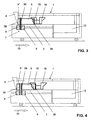
- the device 1 has according to FIG. 1 a machine frame 2, which has a horizontally extending stack support 3.
- the stack support 3 are printed with a conveying device 4 6 ( FIG. 8 ) fed from a scale flow in approximately vertical direction from above.
- Such conveyor belts 4 for shingled streams which consist for example of two belts, are well known to the person skilled in the art and therefore need not be further explained here.
- the stack 5 is supported on the stack side 38 away from the conveyor 4 by a first support and separation element 8 of a support device 7.
- the support device 7 has a second supporting and separating element 9, with which the forming stack 5 in a conventional manner a previously introduced into the stack support 3, the first end plate 10 is supplied.
- the stack side 38 moves in a stack conveying direction 13 to the right. Accordingly, the support device 7 is at least temporarily also moved to the right when forming the stack 5.
- the device 1 also has a pressing device 29 with a first pressing carriage 15 and a second pressing carriage 16.
- the two pressing carriages 15 and 16 are movable both in and against the stack conveying direction 13. Between the two pressing carriages 15 and 16, a stack 5 formed in the manner described above can be pressed in a subsequent method step, ie essentially the compressed air cushion located between the individual printing sheets 6 and the stack 5 thus compressed.
- a second end plate 11th created, which consist for example of wood.
- the arrows 32 shown on the right side of FIG. 1 indicate the directions of the forces with which a previously formed stack 5 is pressed into a stack 5 '.
- a strapping device 12 arranged in this region of the device 1 and known to the person skilled in the art serves for strapping the pressed-out stack 5 '.
- the way in which the stack 5 'is strapped and thus stabilized is not essential to the invention; it is merely a question of being able to transport the pressed-out stack 5' safely to a subsequent further processing.
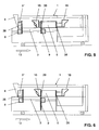
- the first pressing carriage 15, which moves in the direction of the forming stack 5 passes through the second, for example, fork-shaped supporting and separating element 9 and thus takes over the support of the stack 5 on the stack side 38.
- the second supporting and separating element 9 Since the stack 5 is now supported by the first press carriage 15, the second supporting and separating element 9 is also free. It is therefore first moved down and to the left and passes together with the first support and separating element 8 in the FIG. 3 shown position.
- the two supporting and separating elements 8 and 9 drive from below into the stack 5 and thereby separate a subsequent, forming stack 5 "from the stack 5.
- This separation of a stack 5" is the Skilled in the art.
- the prior art is on the EP-A-0 623 542 .
- the second supporting and separating element 9 of the support device 7 is thereby free and in the in FIG. 6 Lower position shown driven.
- the two press carriages 15 and 16 press the stack 5 and drive it into the in FIG. 7 shown position in which he is strapped.
- the second separating element 9 is again in the in FIG. 1 shown position. The described procedure can now be repeated with the subsequent stack 5 ".
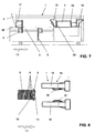
- FIGS. 8 to 18 show the procedures in the FIGS. 8 to 18 shown in plan view of parts of the device 1. From the first press carriage 15 are in FIG. 8 only two spaced apart pressing members 18 are shown, which may be formed substantially the same and extending in the stack conveying direction 13. Each pressing member 18 has a pressing jaw 21 (FIG. Fig. 19, 20 ), on which a movable support member 30 is arranged.
- FIG. 9 the forming stack 5 is supported by the first supporting and separating element 8. Thereafter, the first end plate 10 is moved with the second supporting and separating element 9, not shown here, against the stack 5, so that the first supporting and separating element 8 can be removed.
- FIG. 10 shows the device 1 in a subsequent method step in which the stack 5 is supported on the stack side 38 away from the conveyor device 4 by the first compacting carriage 15. For this purpose, the two support elements 30 are respectively applied to the first end plate 10.
- the stack 5 is here partly in a gap 33 between the two pressing members 18th
- FIG. 11 shows the movement of the second press carriage 16 towards the stack 5.
- the second press carriage 16 moves with two jaws 34 in the intermediate space 33 of the two pressing members 18 in the FIG. 12 shown position.
- the two jaws 34 now abut against the first end plate 10 with a front end and support it, whereby the stack 5 on the stack side 38 is now supported by the second pressing carriage 16.
- the two pressing members 18 of the first press carriage 15 are moved apart transversely to the stack conveying direction 13.
- the two support members 30 in their in FIG. 13 shown retracted position moves.
- the movement may be a pivoting movement, a sliding movement or some other movement.
- the support members 30 do not restrict the gap 33 between the pressing members 18 in this retracted position.
- the gap 33 is thus free for the passage of the stack 5 in the conveying direction 13, wherein the stack 5 could also be substantially wider than in FIG FIG. 13 shown.
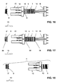
- FIGS. 14 and 15 show the movement of the previously separated by the supporting and separating elements 8, 9 from the stack 5 "stack 5 in the stack conveying direction 13, ie in the direction of the strapping 12.
- the stack 5 is doing on the stack side 39 of the second support and separating element 9 and is supported on the stacking side 38 by the second pressing carriage 16.
- the supporting and separating element 8 supports the forming stack 5 ".
- the FIGS. 16 and 17 show the subsequent movement of the first press carriage 15 in a supporting position in which this rests on the stack side 39, so that the second supporting and separating element 9 can be moved downwards away.
- the the FIG. 7 appropriate FIG. 18 finally shows the stack 5 in the region of the strapping device 12.
- the first press carriage 15 has a frame 17 to which four guide rollers 19 are fastened, on which the first press carriage 15 can be moved on rails, not shown here.
- a transversely extending axis 26 is fixed to the frame 17, on which the two pressing members 18 are mounted, each with a bearing 27 slidably.
- the pressing members 18 may each with a motor 23 and an endless drive member 31 for changing their in FIG. 19 shown distance 35 are moved on the axis 26.
- the distance 35 between the pressing members 18 can thus be reduced or increased.
- Width stack 5 are, for example, those from double benefits.
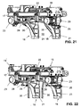
- FIG. 21 On the frame 17, another motor 22 is attached ( FIG. 21 ), which serves to apply the required pressing force when pressing a stack 5.
- the motor 22 acts via two gears 37 ( FIG. 19 ) on racks, not shown here.
- Cables 20 are used to provide electrical power to the motor 22.
- pneumatic and electrical connections and such are provided for a control device not shown here.
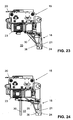
- each have a support member 30 is arranged, which is preferably rod-shaped or bow-shaped.
- the support elements 30 are each at an upper end via a linkage 28 (FIG. FIG. 22 ) pivotally mounted on a pressing jaw 21.
- Each support member 30 is connected via the linkage 28 with a pneumatic actuating cylinder 25 which is fixed to the corresponding pressing jaw 21.
- the control device not shown here.
- the support elements 30 are arranged behind the pressing jaws 21, so that they do not restrict the gap 33 and the maximum width for the passage of the stack 5 is available. Also comparatively wide stack 5 can be passed through the first press carriage 15 without collision.
- the support members 30 are located on one of the conveyor 4 facing side 36 of the pressing jaws 21 and thus the first press carriage 15. The back 24 of the pressing jaws 21 forms a surface on which a stack 5 is pressed.
- the support members 30 are here downwardly directed rod-shaped bracket. However, they can also be plate-shaped and mounted laterally displaceable. In principle, the support elements 30 can also be designed as non-movable surfaces of the conveyor device 4 facing side 36 of the pressing jaws 21. Essential is such a design of the support elements 30, with which they can take over a support function in a stack forming 5, 5 "as long as the second pressing carriage 16 is available. The support elements 30 can be realized with a comparatively small design effort, so that there are no significantly higher production costs, nevertheless the cycle time can be substantially reduced.
Abstract
Description
Die Erfindung betrifft eine Vorrichtung zum Herstellen von Stapeln aus fortlaufend einer sich horizontal erstreckenden Stapelauflage zugeführten, senkrecht aneinander gereihten Druckbogen, mit einer die Druckbogen der Stapelauflage zuführenden Fördervorrichtung und einer zum Bilden eines Stapels in einen sich bildenden Stapel eingreifenden Stützvorrichtung, mit welcher ein sich bildender Stapel stützbar und einer Presseinrichtung übergebbar ist, die einen ersten und einen zweiten Presswagen aufweist, zwischen denen ein gebildeter Stapel abpressbar ist, wobei der erste Presswagen mit einer der Fördervorrichtung abgewendeten Rückseite an den abzupressenden Stapel anlegbar ist.The invention relates to a device for producing stacks of continuously fed to a horizontally extending stack support, vertically aligned printing sheet, with a printing sheet of the stack support feeding conveyor and a for forming a stack in a forming stack engaging support device, with which a forming Stack sustainable and a pressing device can be handed over, which has a first and a second compacting carriage, between which an educated stack can be pressed off, wherein the first compacting carriage with a back side facing away from the conveying device can be applied to the abzupressenden stack.
Nach der Druckmaschine werden Druckbogen für die Weiterverarbeitung zu Büchem, Zeitschriften und dergleichen als sogenannte Stangen gestapelt, siehe z.B.
An solche Verfahren werden hohe Anforderungen bezüglich der Zykluszeit und der Zuverlässigkeit gestellt, um die zugeführte Menge der Druckbogen verarbeiten zu können. Die Zykluszeit sollte möglichst kurz sein, ohne dass hierbei die Zuverlässigkeit beeinträchtigt wird.High demands are placed on such processes with regard to the cycle time and the reliability in order to be able to process the supplied quantity of the printed sheets. The cycle time should be as short as possible without compromising reliability.
Durch die
Der Erfindung liegt die Aufgabe zu Grunde, eine Vorrichtung zu schaffen, welche ebenfalls eine kürzere Zykluszeit ermöglicht, jedoch kostengünstiger ist. Die Aufgabe ist gemäss Anspruch 1 dadurch gelöst,The invention is based on the object to provide a device which also allows a shorter cycle time, but is less expensive. The object is achieved according to
dass der erste Presswagen Stützelemente aufweist, mit denen ein sich bildender Stapel an einer von der Fördervorrichtung abgewendeten Stapelseite abstützbar ist. Eine solche Vorrichtung ermöglicht die Erstellung von aus Druckbogen bestehenden Stapeln in einer besonders kurzen Zykluszeit. Die Vorrichtung kann vergleichsweise kostengünstig hergestellt werden und ist trotzdem zuverlässig.in that the first compacting carriage has supporting elements with which a forming stack can be supported on a stacking side facing away from the conveying device. Such a device enables the creation of stacks consisting of printed sheets in a particularly short cycle time. The device can be manufactured comparatively inexpensively and is nevertheless reliable.
Nach einer Weiterbildung ist vorgesehen, dass der erste Presswagen zwei Pressorgane aufweist, die zum Abpressen eines auf der Stapelauflage gebildeten Stapels jeweils eine von der Fördervorrichtung abgewendete Rückseite aufweisen. Diese Pressorgane sind vorzugsweise in einem Abstand zueinander angeordnet und quer zur Stapelförderrichtung verfahrbar. Der Abstand zwischen den Pressorganen kann dadurch einfach an das Format der Druckbogen bzw. an die Breite des Stapels angepasst werden.According to a development, it is provided that the first compacting carriage has two pressing members, each of which has a rear side facing away from the conveying device for pressing off a stack formed on the stacking support. These pressing members are preferably arranged at a distance from each other and movable transversely to the stack conveying direction. The distance between the pressing members can be easily adapted to the format of the sheet or to the width of the stack.
Nach einer Weiterbildung ist vorgesehen, dass die Stützelemente wenigstens an einem der beiden Pressorgane, an dessen der Fördervorrichtung zugewendeten Seite angeordnet sind. Die Stützelemente können somit zusammen mit den Pressorganen quer zur Stapelförderrichtung verstellt werden. Vorzugsweise ist an jedem Pressorgan ein Stützelement angeordnet. Die Stützelemente sind vorzugsweise von einer inneren in eine äussere Stellung verfahrbar. In der äusseren Stellung beengen sie den Zwischenraum zwischen den Pressorganen nicht. Es können deshalb auch vergleichsweise breite Stapel gebildet werden, beispielsweise Stapel aus Doppelnutzen, d.h. aus zwei zusammenhängend hergestellten, gleichen Produkten, die erst in einem nachfolgenden Verfahrensschritt getrennt werden. Die Stützelemente können beispielsweise als Bügel, Platten oder dergleichen ausgebildet sein und verschwenkt, verschoben oder anderweitig zwischen den beiden Stellungen bewegt werden. Ihr Antrieb erfolgt beispielsweise mit einem Stellzylinder, wobei aber auch andere Antriebsmittel denkbar sind.According to a development it is provided that the support elements are arranged at least on one of the two pressing members, on which the conveyor device facing side. The support elements can thus be adjusted together with the pressing members transversely to the staple conveying direction. Preferably, a support element is arranged on each pressing element. The support elements are preferably movable from an inner to an outer position. In the outer position they do not restrict the space between the pressing organs. It is therefore also possible to form comparatively wide stacks, for example double-use stacks, i. from two cohesively produced, identical products, which are only separated in a subsequent process step. The support members may be formed, for example, as brackets, plates or the like and pivoted, moved or otherwise moved between the two positions. Your drive is done for example with a control cylinder, but other drive means are conceivable.
Weitere vorteilhafte Merkmale ergeben sich aus den abhängigen Patentansprüchen, der nachfolgenden Beschreibung sowie der Zeichnung.Further advantageous features emerge from the dependent claims, the following description and the drawings.
Ausführungsbeispiele der Erfindung werden nachfolgend anhand der Zeichnung näher erläutert. Es zeigen:
- Figuren 1 - 7
- schematische Seitenansichten der erfindungsgemässen Vorrich- tung in unterschiedlichen Phasen eines Verarbeitungs-Zyklus,
- Figuren 8 - 18
- schematische Draufsichten auf Teile der erfindungsgemässen Vor- richtung in unterschiedlichen Phasen eines Verarbeitungs-Zyklus,
Figur 19- eine Ansicht des ersten Presswagens,
Figur 20- eine weitere Ansicht des ersten Presswagens,
Figur 21- eine räumliche Ansicht des ersten Presswagens,
Figur 22- eine weitere räumliche Ansicht des ersten Presswagens und
Figuren - weitere Ansichten des ersten Presswagens.
- FIGS. 1-7
- schematic side views of the device according to the invention in different phases of a processing cycle,
- FIGS. 8-18
- schematic top views of parts of the device according to the invention in different phases of a processing cycle,
- FIG. 19
- a view of the first press car,
- FIG. 20
- another view of the first press car,
- FIG. 21
- a spatial view of the first press car,
- FIG. 22
- another spatial view of the first press car and
- FIGS. 23, 24
- further views of the first press car.
Die Vorrichtung 1 besitzt gemäss
Die Vorrichtung 1 besitzt zudem eine Presseinrichtung 29 mit einem ersten Presswagen 15 und einem zweiten Presswagen 16. Die beiden Presswagen 15 und 16 sind sowohl in als auch entgegen der Stapelförderrichtung 13 verfahrbar. Zwischen den beiden Presswagen 15 und 16 kann ein auf die oben beschriebene Weise gebildeter Stapel 5 in einem nachfolgenden Verfahrensschritt abgepresst, d.h. im Wesentlichen die zwischen den einzelnen Druckbogen 6 befindlichen Luftpolster ausgepresst und der Stapel 5 somit komprimiert werden. An die von der Fördervorrichtung 4 abgewendete Stapelseite 38 wird dazu die genannte ersten Endplatte 10 und an die der Fördervorrichtung 4 zugewendete Stapelseite 39 eine zweite Endplatte 11 angelegt, welche beispielsweise aus Holz bestehen. Die auf der rechten Seite der Figur 1 dargestellten Pfeile 32 deuten die Richtungen der Kräfte an, mit denen ein zuvor gebildeter Stapel 5 zu einem Stapel 5' abgepresst wird. Eine in diesem Bereich der Vorrichtung 1 angeordnete, dem Fachmann bekannte Umreifvorrichtung 12 dient zum Umreifen des abgepressten Stapels 5'. Die Art, wie der Stapel 5' umreift und damit stabilisiert wird, ist für die Erfindung nicht wesentlich, es geht hier lediglich darum, den abgepressten Stapel 5' sicher zu einer nachfolgenden Weiterverarbeitung abtransportieren zu können.The
Bei dem in
Da der Stapel 5 nun vom ersten Presswagen 15 gestützt wird, ist das zweite Stütz- und Trennelement 9 ebenfalls frei. Es wird daher zunächst nach unten sowie nach links verfahren und gelangt gemeinsam mit dem ersten Stütz- und Trennelement 8 in die in
Der nach dem Abtransport des abgepressten und umreiften Stapels 5' ebenfalls freigewordene zweite Presswagen 16 fährt nun ebenfalls nach links und übernimmt schliesslich die Stützfunktion des ersten Presswagens 15. Dies ist in
Zum einfacheren Verständnis sind die Verfahrensabläufe in den
In der
Die
Die
Anhand der
Der erste Presswagen 15 besitzt ein Gestell 17, an dem vier Führungsrollen 19 befestigt sind, an denen der erste Presswagen 15 an hier nicht gezeigten Schienen verfahrbar ist. Weiter ist am Gestell 17 eine sich quer erstreckende Achse 26 befestigt, an welcher die beiden Pressorgane 18 mit jeweils einem Lager 27 verschiebbar gelagert sind. Die Pressorgane 18 können jeweils mit einem Motor 23 und einem endlosen Antriebsorgan 31 zur Veränderung ihres in
Am Gestell 17 ist ein weiterer Motor 22 befestigt (
An den beiden Pressorganen 18 ist jeweils ein Stützelement 30 angeordnet, das vorzugsweise stab- oder bügelförmig ausgebildet ist. Die Stützelemente 30 sind jeweils an einem oberen Ende über ein Gestänge 28 (
Die Stützelemente 30 sind hier nach unten gerichtete stabförmige Bügel. Sie können jedoch auch plattenförmig ausgebildet und seitlich verschiebbar gelagert sein. Grundsätzlich können die Stützelemente 30 auch als nicht bewegbare Flächen der der Fördervorrichtung 4 zugewendeten Seite 36 der Pressbacken 21 ausgebildet sein. Wesentlich ist eine solche Ausbildung der Stützelemente 30, mit der sie bei einem sich bildenden Stapel 5, 5" solange eine Stützfunktion übernehmen können, bis hierzu der zweite Presswagen 16 zur Verfügung steht. Damit kann der erste Presswagen 25, ausser der bisher üblichen Pressfunktion, vorteilhaft auch eine Stützfunktion übernehmen. Die Stützelemente 30 können mit einem vergleichsweise kleinen konstruktiven Aufwand realisiert werden, so dass sich keine wesentlich höheren Herstellungskosten ergeben. Trotzdem kann die Zykluszeit wesentlich vermindert werden.The
Da der zweite Presswagen 16 nach dem Abpressen und ggf. Umreifen eines Stapels unabhängig von dessen Länge zwangsläufig auf den erfolgten Abtransport warten muss, bevor er zur Abstützung des sich ausbildenden neuen Stapels entgegen der Stapelförderrichtung 13 verfahren werden kann, ist die mit der erfindungsgemässen Vorrichtung erreichbare Zeiteinsparung bzw. die Erhöhung der Leistung bei vergleichsweise kurzen Stapeln 5 besonders gross.Since the
Claims (8)
- Apparatus for producing stacks of printed sheets (6) lined up vertically one against the other and fed continuously to a horizontally extending stack support (3), said apparatus comprising a conveyor (4) for feeding the printed sheets (6) to the stack support (3), and a supporting device (7) which moves into a stack being formed to form a stack (5) and by means of which a stack (5) being formed can be supported and transferred to a pressing device (29) consisting of a first pressing carriage (15) and a second pressing carriage (16), between which a formed stack (5) can be compressed, in which case the rear side (24) of the first pressing carriage (15) facing away from the conveyor (4) can be placed against the stack (5) to be compressed, characterized in that the first pressing carriage (15) has supporting elements (30), by which a stack (5) being formed can be supported on the side (38) of the stack facing away from the conveyor (4).
- Apparatus according to Claim 1, characterized in that the first pressing carriage (15) has at least one and preferably two movable supporting elements (30).
- Apparatus according to Claim 2, characterized in that the at least one supporting element (30) can be moved between an inner and an outer position.
- Apparatus according to Claim 3, characterized in that at least two supporting elements (30) can be moved between the inner and the outer position.
- Apparatus according to Claim 2 or 3, characterized in that the at least one supporting element (30) is a swivelling yoke.
- Apparatus according to one of Claims 1 to 5, characterized in that the first pressing carriage (15) has two pressing members (18) mounted so as to be movable perpendicular to the feed direction (13) of the stack.
- Apparatus according to Claim 6, characterized in that the at least one supporting element (30) is arranged on one of the two pressing members (18).
- Apparatus according to one or Claims 1 to 7, characterized in that the supporting elements (30) are arranged on a side (36) of the first pressing carriage (15) facing the conveyor (4).
Priority Applications (5)
| Application Number | Priority Date | Filing Date | Title |
|---|---|---|---|
| AT08405208T ATE532729T1 (en) | 2008-08-29 | 2008-08-29 | METHOD AND DEVICE FOR PRODUCING STACKS CONSISTING OF PRINTED SHEETS |
| EP08405208A EP2159177B1 (en) | 2008-08-29 | 2008-08-29 | Device and method for producing piles of printed sheets |
| JP2009196171A JP5436098B2 (en) | 2008-08-29 | 2009-08-27 | Method and apparatus for forming an assembly of printed paper |
| US12/549,660 US8376346B2 (en) | 2008-08-29 | 2009-08-28 | Device and method for producing stacks composed of printed sheets |
| CN200910170614.3A CN101659328B (en) | 2008-08-29 | 2009-08-28 | Device and method for producing piles of printed sheets |
Applications Claiming Priority (1)
| Application Number | Priority Date | Filing Date | Title |
|---|---|---|---|
| EP08405208A EP2159177B1 (en) | 2008-08-29 | 2008-08-29 | Device and method for producing piles of printed sheets |
Publications (2)
| Publication Number | Publication Date |
|---|---|
| EP2159177A1 EP2159177A1 (en) | 2010-03-03 |
| EP2159177B1 true EP2159177B1 (en) | 2011-11-09 |
Family
ID=40348840
Family Applications (1)
| Application Number | Title | Priority Date | Filing Date |
|---|---|---|---|
| EP08405208A Not-in-force EP2159177B1 (en) | 2008-08-29 | 2008-08-29 | Device and method for producing piles of printed sheets |
Country Status (5)
| Country | Link |
|---|---|
| US (1) | US8376346B2 (en) |
| EP (1) | EP2159177B1 (en) |
| JP (1) | JP5436098B2 (en) |
| CN (1) | CN101659328B (en) |
| AT (1) | ATE532729T1 (en) |
Families Citing this family (5)
| Publication number | Priority date | Publication date | Assignee | Title |
|---|---|---|---|---|
| FR2983464B1 (en) | 2011-12-05 | 2014-06-27 | Solystic | STACKING DEVICE FOR SINGLE STACKED FLAT OBJECTS AND POSTAL SORTING MACHINE |
| CN102530290A (en) * | 2011-12-22 | 2012-07-04 | 上海烟草集团有限责任公司 | Method for warehousing cigarette cases via automatic logistics system |
| EP2695741B1 (en) * | 2012-08-09 | 2015-03-04 | Müller Martini Holding AG | Sewing machine |
| EP2778105B1 (en) * | 2013-03-11 | 2016-10-26 | Wincor Nixdorf International GmbH | Apparatus and method for filling a transport container with vouchers |
| CN113928903A (en) * | 2021-10-18 | 2022-01-14 | 东莞市浩信精密机械有限公司 | Non-stop paper separating mechanism for book binding machine |
Family Cites Families (12)
| Publication number | Priority date | Publication date | Assignee | Title |
|---|---|---|---|---|
| CH663397A5 (en) * | 1984-05-11 | 1987-12-15 | Grapha Holding Ag | STACKING DEVICE FOR PRINTED SHEET. |
| DE4117434A1 (en) * | 1991-05-28 | 1992-12-03 | Winkler Duennebier Kg Masch | METHOD AND DEVICE FOR STACKING |
| DE4202540A1 (en) | 1992-01-30 | 1993-08-05 | Giebeler Gmbh & Co Kg Robert | METHOD AND DEVICE FOR PRODUCING DEFINED STACK OF FOLDED OR UNFOLDED SHEETS OR SHEET-SHAPED OBJECTS |
| JP4318322B2 (en) | 1993-05-07 | 2009-08-19 | グラプハ−ホルディング・アクチエンゲゼルシヤフト | Apparatus for forming a stack oriented in a vertical direction with respect to papers standing in parallel |
| JP3443172B2 (en) * | 1994-06-22 | 2003-09-02 | 大日本印刷株式会社 | Printing book accumulator |
| DE59806580D1 (en) | 1997-03-18 | 2003-01-23 | Grapha Holding Ag | Device for forming a partial stack which extends perpendicularly to the printed sheets arranged in a row |
| FR2777876B1 (en) * | 1998-04-24 | 2000-06-30 | Realisations Etudes Et Commerc | DEVICE FOR STACKING AND TRANSFERRING PRINTED NOTEBOOKS IN THE FORM OF CARTRIDGES |
| JP2000118511A (en) * | 1998-08-13 | 2000-04-25 | Gunze Ltd | Printing sheet binder |
| CA2491774C (en) * | 2002-07-19 | 2011-12-13 | Ferag Ag | Method and device for producing and strapping recumbent stacks of printed products |
| EP1405809B1 (en) | 2002-10-02 | 2009-07-01 | Müller Martini Holding AG | Device for forming parcels of stacked products |
| CA2617971A1 (en) * | 2005-08-05 | 2007-02-15 | Glory Ltd. | Paper-sheet storing and feeding device |
| EP1816098B1 (en) * | 2006-02-02 | 2010-03-31 | Müller Martini Holding AG | Method and device for forming stacks |
-
2008
- 2008-08-29 EP EP08405208A patent/EP2159177B1/en not_active Not-in-force
- 2008-08-29 AT AT08405208T patent/ATE532729T1/en active
-
2009
- 2009-08-27 JP JP2009196171A patent/JP5436098B2/en not_active Expired - Fee Related
- 2009-08-28 US US12/549,660 patent/US8376346B2/en not_active Expired - Fee Related
- 2009-08-28 CN CN200910170614.3A patent/CN101659328B/en not_active Expired - Fee Related
Also Published As
| Publication number | Publication date |
|---|---|
| US20100050572A1 (en) | 2010-03-04 |
| CN101659328B (en) | 2014-03-05 |
| CN101659328A (en) | 2010-03-03 |
| JP2010052946A (en) | 2010-03-11 |
| US8376346B2 (en) | 2013-02-19 |
| JP5436098B2 (en) | 2014-03-05 |
| EP2159177A1 (en) | 2010-03-03 |
| ATE532729T1 (en) | 2011-11-15 |
Similar Documents
| Publication | Publication Date | Title |
|---|---|---|
| EP0847949B1 (en) | Device for forming a stack of printed sheets, where these are piled on the edge | |
| EP2072430A1 (en) | Packet gripper for a palletising device and method for palletising packets | |
| EP2159177B1 (en) | Device and method for producing piles of printed sheets | |
| DE3836214C2 (en) | ||
| EP2457858A1 (en) | Device and method for the formation of packages from printed products | |
| DE2716806A1 (en) | DEVICE FOR STACKING FLAT MATERIAL PIECES | |
| DE3006229C2 (en) | System for sorting and filing stacks of sheets | |
| DE2547149B2 (en) | Stacking device for loading a multi-stage press | |
| DE3540203C2 (en) | Device for conveying stacks of paper | |
| DE2508745C2 (en) | Device for accumulating individually by means of a transport device fed paper sheets into stacks and for further transporting these stacks | |
| EP1405809B1 (en) | Device for forming parcels of stacked products | |
| DE102007013382A1 (en) | Pressed bale manufacturing method, involves pressing partial pressed bales with each other using preload force that acts perpendicular to flat sides in pressing direction during connecting partial pressed bales to pressed bales | |
| EP2498983B1 (en) | Apparatus and method for forming stacks of bags | |
| EP0597387A1 (en) | Press with transfer arrangement for metal sheets | |
| EP2628591B1 (en) | Press for manufacturing pressed bales | |
| EP2138439B1 (en) | Device for stacking flat products, in particular printed products | |
| EP1523443A1 (en) | Method and device for forming horizontal stacks of printed products and securing said stacks with straps | |
| EP1464602B1 (en) | Device for forming a stream of flat objects in shingled formation | |
| EP0958217A1 (en) | Stack changing device | |
| EP1857182A2 (en) | Method for transferring the beginning of a sheet film or a film mesh from a thermoforming machine to a cutting mill and transfer device | |
| EP2192067B1 (en) | Stacking device for printed products | |
| EP0810174B1 (en) | Device for vertically stacking printed products | |
| DE4406337C2 (en) | Device for welding the strands of strands, in particular copper strands | |
| DE202017103053U1 (en) | Prepress and system for the continuous production of material plates and transport device for receiving the press belt | |
| EP2316767B1 (en) | Device and method for manufacturing printed product stacks |
Legal Events
| Date | Code | Title | Description |
|---|---|---|---|
| PUAI | Public reference made under article 153(3) epc to a published international application that has entered the european phase |
Free format text: ORIGINAL CODE: 0009012 |
|
| AK | Designated contracting states |
Kind code of ref document: A1 Designated state(s): AT BE BG CH CY CZ DE DK EE ES FI FR GB GR HR HU IE IS IT LI LT LU LV MC MT NL NO PL PT RO SE SI SK TR |
|
| AX | Request for extension of the european patent |
Extension state: AL BA MK RS |
|
| 17P | Request for examination filed |
Effective date: 20100614 |
|
| 17Q | First examination report despatched |
Effective date: 20100903 |
|
| AKX | Designation fees paid |
Designated state(s): AT BE BG CH CY CZ DE DK EE ES FI FR GB GR HR HU IE IS IT LI LT LU LV MC MT NL NO PL PT RO SE SI SK TR |
|
| RIC1 | Information provided on ipc code assigned before grant |
Ipc: B65B 27/08 20060101ALI20110329BHEP Ipc: B65H 31/06 20060101AFI20110329BHEP Ipc: B65H 33/02 20060101ALI20110329BHEP |
|
| GRAP | Despatch of communication of intention to grant a patent |
Free format text: ORIGINAL CODE: EPIDOSNIGR1 |
|
| GRAS | Grant fee paid |
Free format text: ORIGINAL CODE: EPIDOSNIGR3 |
|
| GRAA | (expected) grant |
Free format text: ORIGINAL CODE: 0009210 |
|
| AK | Designated contracting states |
Kind code of ref document: B1 Designated state(s): AT BE BG CH CY CZ DE DK EE ES FI FR GB GR HR HU IE IS IT LI LT LU LV MC MT NL NO PL PT RO SE SI SK TR |
|
| REG | Reference to a national code |
Ref country code: GB Ref legal event code: FG4D Free format text: NOT ENGLISH |
|
| REG | Reference to a national code |
Ref country code: CH Ref legal event code: EP |
|
| REG | Reference to a national code |
Ref country code: IE Ref legal event code: FG4D Free format text: LANGUAGE OF EP DOCUMENT: GERMAN |
|
| REG | Reference to a national code |
Ref country code: DE Ref legal event code: R096 Ref document number: 502008005521 Country of ref document: DE Effective date: 20120216 |
|
| REG | Reference to a national code |
Ref country code: NL Ref legal event code: VDEP Effective date: 20111109 |
|
| LTIE | Lt: invalidation of european patent or patent extension |
Effective date: 20111109 |
|
| PG25 | Lapsed in a contracting state [announced via postgrant information from national office to epo] |
Ref country code: IS Free format text: LAPSE BECAUSE OF FAILURE TO SUBMIT A TRANSLATION OF THE DESCRIPTION OR TO PAY THE FEE WITHIN THE PRESCRIBED TIME-LIMIT Effective date: 20120309 Ref country code: NO Free format text: LAPSE BECAUSE OF FAILURE TO SUBMIT A TRANSLATION OF THE DESCRIPTION OR TO PAY THE FEE WITHIN THE PRESCRIBED TIME-LIMIT Effective date: 20120209 Ref country code: LT Free format text: LAPSE BECAUSE OF FAILURE TO SUBMIT A TRANSLATION OF THE DESCRIPTION OR TO PAY THE FEE WITHIN THE PRESCRIBED TIME-LIMIT Effective date: 20111109 |
|
| PG25 | Lapsed in a contracting state [announced via postgrant information from national office to epo] |
Ref country code: LV Free format text: LAPSE BECAUSE OF FAILURE TO SUBMIT A TRANSLATION OF THE DESCRIPTION OR TO PAY THE FEE WITHIN THE PRESCRIBED TIME-LIMIT Effective date: 20111109 Ref country code: PL Free format text: LAPSE BECAUSE OF FAILURE TO SUBMIT A TRANSLATION OF THE DESCRIPTION OR TO PAY THE FEE WITHIN THE PRESCRIBED TIME-LIMIT Effective date: 20111109 Ref country code: GR Free format text: LAPSE BECAUSE OF FAILURE TO SUBMIT A TRANSLATION OF THE DESCRIPTION OR TO PAY THE FEE WITHIN THE PRESCRIBED TIME-LIMIT Effective date: 20120210 Ref country code: PT Free format text: LAPSE BECAUSE OF FAILURE TO SUBMIT A TRANSLATION OF THE DESCRIPTION OR TO PAY THE FEE WITHIN THE PRESCRIBED TIME-LIMIT Effective date: 20120309 Ref country code: NL Free format text: LAPSE BECAUSE OF FAILURE TO SUBMIT A TRANSLATION OF THE DESCRIPTION OR TO PAY THE FEE WITHIN THE PRESCRIBED TIME-LIMIT Effective date: 20111109 Ref country code: SE Free format text: LAPSE BECAUSE OF FAILURE TO SUBMIT A TRANSLATION OF THE DESCRIPTION OR TO PAY THE FEE WITHIN THE PRESCRIBED TIME-LIMIT Effective date: 20111109 Ref country code: SI Free format text: LAPSE BECAUSE OF FAILURE TO SUBMIT A TRANSLATION OF THE DESCRIPTION OR TO PAY THE FEE WITHIN THE PRESCRIBED TIME-LIMIT Effective date: 20111109 Ref country code: HR Free format text: LAPSE BECAUSE OF FAILURE TO SUBMIT A TRANSLATION OF THE DESCRIPTION OR TO PAY THE FEE WITHIN THE PRESCRIBED TIME-LIMIT Effective date: 20111109 |
|
| REG | Reference to a national code |
Ref country code: IE Ref legal event code: FD4D |
|
| PG25 | Lapsed in a contracting state [announced via postgrant information from national office to epo] |
Ref country code: CY Free format text: LAPSE BECAUSE OF FAILURE TO SUBMIT A TRANSLATION OF THE DESCRIPTION OR TO PAY THE FEE WITHIN THE PRESCRIBED TIME-LIMIT Effective date: 20111109 |
|
| PG25 | Lapsed in a contracting state [announced via postgrant information from national office to epo] |
Ref country code: BG Free format text: LAPSE BECAUSE OF FAILURE TO SUBMIT A TRANSLATION OF THE DESCRIPTION OR TO PAY THE FEE WITHIN THE PRESCRIBED TIME-LIMIT Effective date: 20120209 Ref country code: IE Free format text: LAPSE BECAUSE OF FAILURE TO SUBMIT A TRANSLATION OF THE DESCRIPTION OR TO PAY THE FEE WITHIN THE PRESCRIBED TIME-LIMIT Effective date: 20111109 Ref country code: EE Free format text: LAPSE BECAUSE OF FAILURE TO SUBMIT A TRANSLATION OF THE DESCRIPTION OR TO PAY THE FEE WITHIN THE PRESCRIBED TIME-LIMIT Effective date: 20111109 Ref country code: DK Free format text: LAPSE BECAUSE OF FAILURE TO SUBMIT A TRANSLATION OF THE DESCRIPTION OR TO PAY THE FEE WITHIN THE PRESCRIBED TIME-LIMIT Effective date: 20111109 Ref country code: SK Free format text: LAPSE BECAUSE OF FAILURE TO SUBMIT A TRANSLATION OF THE DESCRIPTION OR TO PAY THE FEE WITHIN THE PRESCRIBED TIME-LIMIT Effective date: 20111109 Ref country code: CZ Free format text: LAPSE BECAUSE OF FAILURE TO SUBMIT A TRANSLATION OF THE DESCRIPTION OR TO PAY THE FEE WITHIN THE PRESCRIBED TIME-LIMIT Effective date: 20111109 |
|
| PG25 | Lapsed in a contracting state [announced via postgrant information from national office to epo] |
Ref country code: RO Free format text: LAPSE BECAUSE OF FAILURE TO SUBMIT A TRANSLATION OF THE DESCRIPTION OR TO PAY THE FEE WITHIN THE PRESCRIBED TIME-LIMIT Effective date: 20111109 |
|
| PLBE | No opposition filed within time limit |
Free format text: ORIGINAL CODE: 0009261 |
|
| STAA | Information on the status of an ep patent application or granted ep patent |
Free format text: STATUS: NO OPPOSITION FILED WITHIN TIME LIMIT |
|
| 26N | No opposition filed |
Effective date: 20120810 |
|
| REG | Reference to a national code |
Ref country code: DE Ref legal event code: R097 Ref document number: 502008005521 Country of ref document: DE Effective date: 20120810 |
|
| BERE | Be: lapsed |
Owner name: MULLER MARTINI HOLDING A.G. Effective date: 20120831 |
|
| PG25 | Lapsed in a contracting state [announced via postgrant information from national office to epo] |
Ref country code: MC Free format text: LAPSE BECAUSE OF NON-PAYMENT OF DUE FEES Effective date: 20120831 |
|
| GBPC | Gb: european patent ceased through non-payment of renewal fee |
Effective date: 20120829 |
|
| PG25 | Lapsed in a contracting state [announced via postgrant information from national office to epo] |
Ref country code: ES Free format text: LAPSE BECAUSE OF FAILURE TO SUBMIT A TRANSLATION OF THE DESCRIPTION OR TO PAY THE FEE WITHIN THE PRESCRIBED TIME-LIMIT Effective date: 20120220 |
|
| PG25 | Lapsed in a contracting state [announced via postgrant information from national office to epo] |
Ref country code: BE Free format text: LAPSE BECAUSE OF NON-PAYMENT OF DUE FEES Effective date: 20120831 |
|
| PG25 | Lapsed in a contracting state [announced via postgrant information from national office to epo] |
Ref country code: FI Free format text: LAPSE BECAUSE OF FAILURE TO SUBMIT A TRANSLATION OF THE DESCRIPTION OR TO PAY THE FEE WITHIN THE PRESCRIBED TIME-LIMIT Effective date: 20111109 |
|
| PG25 | Lapsed in a contracting state [announced via postgrant information from national office to epo] |
Ref country code: GB Free format text: LAPSE BECAUSE OF NON-PAYMENT OF DUE FEES Effective date: 20120829 |
|
| PG25 | Lapsed in a contracting state [announced via postgrant information from national office to epo] |
Ref country code: MT Free format text: LAPSE BECAUSE OF FAILURE TO SUBMIT A TRANSLATION OF THE DESCRIPTION OR TO PAY THE FEE WITHIN THE PRESCRIBED TIME-LIMIT Effective date: 20111109 |
|
| PG25 | Lapsed in a contracting state [announced via postgrant information from national office to epo] |
Ref country code: TR Free format text: LAPSE BECAUSE OF FAILURE TO SUBMIT A TRANSLATION OF THE DESCRIPTION OR TO PAY THE FEE WITHIN THE PRESCRIBED TIME-LIMIT Effective date: 20111109 |
|
| PG25 | Lapsed in a contracting state [announced via postgrant information from national office to epo] |
Ref country code: LU Free format text: LAPSE BECAUSE OF NON-PAYMENT OF DUE FEES Effective date: 20120829 |
|
| PG25 | Lapsed in a contracting state [announced via postgrant information from national office to epo] |
Ref country code: HU Free format text: LAPSE BECAUSE OF FAILURE TO SUBMIT A TRANSLATION OF THE DESCRIPTION OR TO PAY THE FEE WITHIN THE PRESCRIBED TIME-LIMIT Effective date: 20080829 |
|
| REG | Reference to a national code |
Ref country code: FR Ref legal event code: PLFP Year of fee payment: 8 |
|
| PGFP | Annual fee paid to national office [announced via postgrant information from national office to epo] |
Ref country code: DE Payment date: 20150812 Year of fee payment: 8 |
|
| PGFP | Annual fee paid to national office [announced via postgrant information from national office to epo] |
Ref country code: FR Payment date: 20150824 Year of fee payment: 8 Ref country code: AT Payment date: 20150824 Year of fee payment: 8 |
|
| PGFP | Annual fee paid to national office [announced via postgrant information from national office to epo] |
Ref country code: IT Payment date: 20150831 Year of fee payment: 8 |
|
| PGFP | Annual fee paid to national office [announced via postgrant information from national office to epo] |
Ref country code: CH Payment date: 20151120 Year of fee payment: 8 |
|
| REG | Reference to a national code |
Ref country code: DE Ref legal event code: R119 Ref document number: 502008005521 Country of ref document: DE |
|
| REG | Reference to a national code |
Ref country code: CH Ref legal event code: PL |
|
| REG | Reference to a national code |
Ref country code: AT Ref legal event code: MM01 Ref document number: 532729 Country of ref document: AT Kind code of ref document: T Effective date: 20160829 |
|
| PG25 | Lapsed in a contracting state [announced via postgrant information from national office to epo] |
Ref country code: LI Free format text: LAPSE BECAUSE OF NON-PAYMENT OF DUE FEES Effective date: 20160831 Ref country code: CH Free format text: LAPSE BECAUSE OF NON-PAYMENT OF DUE FEES Effective date: 20160831 |
|
| REG | Reference to a national code |
Ref country code: FR Ref legal event code: ST Effective date: 20170428 |
|
| PG25 | Lapsed in a contracting state [announced via postgrant information from national office to epo] |
Ref country code: AT Free format text: LAPSE BECAUSE OF NON-PAYMENT OF DUE FEES Effective date: 20160829 |
|
| PG25 | Lapsed in a contracting state [announced via postgrant information from national office to epo] |
Ref country code: FR Free format text: LAPSE BECAUSE OF NON-PAYMENT OF DUE FEES Effective date: 20160831 Ref country code: DE Free format text: LAPSE BECAUSE OF NON-PAYMENT OF DUE FEES Effective date: 20170301 |
|
| PG25 | Lapsed in a contracting state [announced via postgrant information from national office to epo] |
Ref country code: IT Free format text: LAPSE BECAUSE OF NON-PAYMENT OF DUE FEES Effective date: 20160829 |