EP2159172A1 - Convoyeur de type caroussel - Google Patents
Convoyeur de type caroussel Download PDFInfo
- Publication number
- EP2159172A1 EP2159172A1 EP08163531A EP08163531A EP2159172A1 EP 2159172 A1 EP2159172 A1 EP 2159172A1 EP 08163531 A EP08163531 A EP 08163531A EP 08163531 A EP08163531 A EP 08163531A EP 2159172 A1 EP2159172 A1 EP 2159172A1
- Authority
- EP
- European Patent Office
- Prior art keywords
- bearing pin
- gripping
- locking
- bearing
- transport star
- Prior art date
- Legal status (The legal status is an assumption and is not a legal conclusion. Google has not performed a legal analysis and makes no representation as to the accuracy of the status listed.)
- Granted
Links
- 230000000295 complement effect Effects 0.000 claims description 16
- 238000006073 displacement reaction Methods 0.000 claims description 10
- 230000006835 compression Effects 0.000 description 4
- 238000007906 compression Methods 0.000 description 4
- 238000004519 manufacturing process Methods 0.000 description 4
- 230000006978 adaptation Effects 0.000 description 3
- 238000013461 design Methods 0.000 description 3
- 238000003860 storage Methods 0.000 description 3
- 230000002950 deficient Effects 0.000 description 2
- 230000000694 effects Effects 0.000 description 2
- 239000000463 material Substances 0.000 description 2
- 101100110009 Caenorhabditis elegans asd-2 gene Proteins 0.000 description 1
- 238000005299 abrasion Methods 0.000 description 1
- 239000000853 adhesive Substances 0.000 description 1
- 230000001070 adhesive effect Effects 0.000 description 1
- 238000013459 approach Methods 0.000 description 1
- 235000013361 beverage Nutrition 0.000 description 1
- 230000015572 biosynthetic process Effects 0.000 description 1
- 210000000078 claw Anatomy 0.000 description 1
- 239000011248 coating agent Substances 0.000 description 1
- 238000000576 coating method Methods 0.000 description 1
- 230000001419 dependent effect Effects 0.000 description 1
- 238000003780 insertion Methods 0.000 description 1
- 230000037431 insertion Effects 0.000 description 1
- 238000012423 maintenance Methods 0.000 description 1
- 230000007246 mechanism Effects 0.000 description 1
- 238000000034 method Methods 0.000 description 1
- 238000003825 pressing Methods 0.000 description 1
- 238000012545 processing Methods 0.000 description 1
- 238000003892 spreading Methods 0.000 description 1
- 230000003068 static effect Effects 0.000 description 1
- 238000012549 training Methods 0.000 description 1
Images


Classifications
-
- B—PERFORMING OPERATIONS; TRANSPORTING
- B65—CONVEYING; PACKING; STORING; HANDLING THIN OR FILAMENTARY MATERIAL
- B65G—TRANSPORT OR STORAGE DEVICES, e.g. CONVEYORS FOR LOADING OR TIPPING, SHOP CONVEYOR SYSTEMS OR PNEUMATIC TUBE CONVEYORS
- B65G47/00—Article or material-handling devices associated with conveyors; Methods employing such devices
- B65G47/74—Feeding, transfer, or discharging devices of particular kinds or types
- B65G47/84—Star-shaped wheels or devices having endless travelling belts or chains, the wheels or devices being equipped with article-engaging elements
- B65G47/846—Star-shaped wheels or wheels equipped with article-engaging elements
- B65G47/847—Star-shaped wheels or wheels equipped with article-engaging elements the article-engaging elements being grippers
-
- B—PERFORMING OPERATIONS; TRANSPORTING
- B65—CONVEYING; PACKING; STORING; HANDLING THIN OR FILAMENTARY MATERIAL
- B65G—TRANSPORT OR STORAGE DEVICES, e.g. CONVEYORS FOR LOADING OR TIPPING, SHOP CONVEYOR SYSTEMS OR PNEUMATIC TUBE CONVEYORS
- B65G29/00—Rotary conveyors, e.g. rotating discs, arms, star-wheels or cones
-
- B—PERFORMING OPERATIONS; TRANSPORTING
- B65—CONVEYING; PACKING; STORING; HANDLING THIN OR FILAMENTARY MATERIAL
- B65G—TRANSPORT OR STORAGE DEVICES, e.g. CONVEYORS FOR LOADING OR TIPPING, SHOP CONVEYOR SYSTEMS OR PNEUMATIC TUBE CONVEYORS
- B65G2201/00—Indexing codes relating to handling devices, e.g. conveyors, characterised by the type of product or load being conveyed or handled
- B65G2201/02—Articles
- B65G2201/0235—Containers
- B65G2201/0244—Bottles
-
- B—PERFORMING OPERATIONS; TRANSPORTING
- B65—CONVEYING; PACKING; STORING; HANDLING THIN OR FILAMENTARY MATERIAL
- B65G—TRANSPORT OR STORAGE DEVICES, e.g. CONVEYORS FOR LOADING OR TIPPING, SHOP CONVEYOR SYSTEMS OR PNEUMATIC TUBE CONVEYORS
- B65G2207/00—Indexing codes relating to constructional details, configuration and additional features of a handling device, e.g. Conveyors
- B65G2207/48—Wear protection or indication features
Definitions
- the present invention relates to a star conveyor for vessels or the like body, with a rotatable body and a plurality of circumferentially spaced gripping means for gripping the vessels, each gripping means pairwise corresponding, in particular to the body radially arranged gripping arms which coupled by a centering in their gripping movement are.
- Such transport stars for vessels are basically known, for example, from filling machines from the beverage industry.
- the transport star are supplied, inter alia, via conveyor belts vessels, which are then detected by the paired gripping arms and taken by the rotating transport star from the feeding conveyor belt.
- the transport star then rotates until the vessels taken from the conveyor belt are in the correct position, for example above a new conveyor belt.
- Via a corresponding control device then open the closed gripper arms and release the vessels.
- Transport stars are known from the prior art, in which the gripping arms are arranged pointing radially outwards in a basic body constructed from two parallel, circular rings. These gripping arms are movably mounted parallel to the axis of rotation of the base body and can thus be moved against each other from an opening into a closed position and vice versa. The control of this opening or closing process is realized in different ways.
- a transport star of the type mentioned above is in the DE 296 07 868 U1 described here, in which case the gripping arms are designed as a double lever, with substantially radially outwardly pointing gripping tongs and substantially radially inwardly facing counter-arms. Between these counter-arms, an expansion body is arranged, which urges the two counter-arms to the outside and thus brings the radially outwardly facing gripping arms in a closed position. An opening position is achieved by the spreader again allows the approach of the counter-arms, whereby the gripping arms open again.
- this embodiment is very susceptible to errors because of their rigid gripping mechanisms, since any inaccuracies can not be compensated.
- the grippers also consist of radially outwardly facing gripping arms.
- only one gripping arm has a radially inwardly pointing counter-arm.
- This counter-arm abuts against a camshaft arranged perpendicular to the axis of rotation of the main body, which forms the control element.
- the gripping device is brought into a closed or open position.
- the pressing apart of the gripping arms from the closed to the open position by a compression spring which is arranged between the two radially outwardly gripping arms. So that the gripping movement is carried out uniformly, the two gripper arms are coupled together by a centering.
- the disadvantage here has been found, however, that a wear of the centering a complex repair is necessary, which also leads to a long production downtime and high costs.
- FIG. 1 Another embodiment of a transport star is by the DE 203 05 988 U1 disclosed.
- separate gripping devices are arranged on the underside of a support ring, so that defective gripping devices can be easily replaced.
- the gripper arms of each gripper are again arranged in pairs corresponding to the support ring pointing radially outward and via a control device from the closed to the open position and vice versa movable.
- the gripping arms themselves consist of gripping arms pointing radially outwards and counter-arms pointing radially inwards.
- On the counter-arms a centering toothing is arranged such that the gripping arms are coupled in their movement between the open and closed positions with each other.
- a disadvantage has also been found here that at a wear Although the gripping arms, in contrast to the rest of the prior art, are very easy to replace the centering, this replacement still means a relatively long production downtime.
- this object is achieved by a star conveyor for vessels or the like body, with a rotatable body and several distributed over the circumference gripping means for gripping the vessels, each gripping means pairwise corresponding, in particular to the body radially arranged gripping arms, which by a centering in their Gripping movement are coupled together, wherein at least one gripping arm has an adjusting device by means of which the operative engagement of the centering toothing is adjustable.
- the between the pairwise corresponding arranged gripping arms acting centering is basically subject to heavy wear in transport star due to the very high opening and closing movement rates. If the entire gripping arm or even the entire gripping device has to be exchanged in the prior art in the case of a worn centering toothing, the solution according to the invention makes possible a very quick and simple readjustment, which entails only a small production standstill. Thus, as soon as a gripping device has completed a certain number of working cycles and the centering toothing has reached a maximum permissible wear state, readjustment can very quickly take place by means of the adjusting device, so that the centering toothing again has full functionality. Only when reaching a maximum wear limit, then the gripping arms, or depending on the training, for example, in a releasably formed in the gripping arm centering, the centering be replaced itself.
- the toothed element arranged on the at least one gripping arm that is to say the toothed element which can be manipulated together with the gripping arm by means of the adjusting device, can be moved toward the other complementary toothed element by means of the adjusting device for setting a substantially backlash-free rotational toothing.
- adjustment devices or adjustable toothing elements are arranged on both gripper arms, this naturally also applies correspondingly to both gripping arms.
- play-free means such an arrangement of the two toothed elements that an optimal function or an optimal operative engagement of the centering toothing is ensured.
- the at least one gripping arm is mounted on an eccentric bearing cylinder of a bearing pin on a central unit of the gripping device, wherein the eccentric bearing cylinder acts as an adjusting device upon rotation of the bearing pin.
- central unit here is a housing to understand that receives the bearing pin substantially stationary and thus allows the storage of the gripping arms.
- the bearing pin penetrates preferably a bearing bore of the gripper arm, said bearing bore is complementary to the eccentric bearing cylinder.
- the gripper arm is mounted substantially accurately and in particular rotatable about the eccentric bearing cylinder on the bearing pin and on this at the central unit of the gripping device.
- the eccentric bearing cylinder acts not only as an adjusting device but also as a rotary bearing for the gripping arm and ensures the gripping movement between the open and closed positions.
- the axis of rotation of the gripper arm is equal to the symmetry longitudinal axis of the eccentric bearing cylinder.
- the bearing bore and / or the bearing cylinder is preferably provided with a friction-reducing coating or a similar element, to reduce wear.
- a friction-reducing coating or a similar element to reduce wear.
- the eccentric bearing cylinder in the bearing bore of the gripping arm Due to the precise arrangement of the eccentric bearing cylinder in the bearing bore of the gripping arm is free of play and very precisely displaced upon rotation of the bearing pin, so that an exact readjustment of the centering is possible.
- the toothing element of the centering releasably lockable on the gripper arm to compensate for any angular deviations in the displacement of the gripping arm by the rotation of the eccentric bearing cylinder.
- the use of a latched bearing device between the toothed element and the gripper arm can be used.
- the bearing pin concentric with its adjusting axis, in particular at its free ends a bearing pin head and a Lagerbolzenfuss, which are arranged in each complementary bearing pin receptacles on the central unit and wherein the axis of symmetry of the eccentric bearing cylinder, hereinafter referred to as the cylinder axis, eccentrically and axially parallel to this adjustment axis is arranged.
- the bearing pin head and the Lagerbolzenfuss the bearing pin can be accurately placed and fixed to the central unit, so that by a rotation of the bearing pin in its corresponding bearing mounts to the central unit a backlash adjustment of the centering is possible.
- the gripping arm mounted on the bearing cylinder moves relative to the alignment, so that it, depending on the direction of rotation, on the correspondingly arranged other toothing element the centering gear moved or moved away.
- the bearing bolt head and the bearing bolt foot are preferably rotationally symmetrical in their outer circumference, so that the toothed element which can be moved via the adjusting device can be arranged in any position by a simple rotation of the bearing bolt.
- the eccentric bearing cylinder is arranged in the direction of the adjusting axis between the bearing pin head and the Lagerbolzenfuss. In this way, the static stability of the mounting of the gripper arm on the eccentric bearing cylinder is increased.
- the bearing pin is detachably mounted in the central unit of the gripping device by means of a locking device, in particular rotatably mounted. In this way, it is ensured that after an adjustment of the centering, so after rotation of the bearing pin, this adjustment is maintained even during the subsequent operation of the transport star.
- the locking device has a locking element on the bearing pin head and / or on Lagerbolzenfuss and at least one complementary locking counter-element on the central unit, wherein the locking element in a Lagerbolzenarretsammlungswolf the bearing pin rotationally releasably engages in the locking counter-element.
- Such a locking element may for example be an inner n-edge and in particular an inner 12 edge, wherein the locking counter element is then designed as a complementary outer n-edge or outward edge 12.
- the locking element and the locking counter-element are designed such that the locking engagement by an axial displacement in the direction of the alignment axis of the bearing pin is releasably and by an opposite axial displacement can be restored.
- the bearing pin is displaced axially, so that this locking engagement triggers.
- the bearing pin can be rotated and thus the centering be readjusted.
- the bearing pin can be moved axially opposite again, so that the locking element engages again in the Arret istsussielement.
- the bearing cylinder in the direction of the alignment axis has a sufficient length to prevent it from slipping out of its storage in the bearing bore on the gripping arm when moving the bearing pin for disengaging the locking engagement.
- the bearing pin and in particular the bearing pin head and / or Lagerbolzenfus s an adjustment and in particular a freely accessible from the outside of the transport star inner 6-Kant, for manipulating the locking engagement between locking element and Arret istsussielement and / or rotation of the bearing pin for setting the operative engagement the centering.
- the aforesaid adjusting means thus makes it possible to carry out the aforesaid axial displacement for the purpose of releasing the locking engagement and / or the rotation of the bearing pin in order to adjust the centering toothing.
- other devices known in the art may also be used herein as such an adjustment means.
- a fixing means for releasably locking the bearing pin is provided against the displacement in the axial direction.
- a fixing means may for example be a releasable adhesive bond, which acts between the bearing pin and its bearing mounts, or a corresponding mechanical fixing means, which is engageable with the bearing pin or its storage in operative engagement and out of operative engagement.
- the bearing pin and / or the Lagerbolzenfuss are arranged on at least one fastening means, in particular detachably on the bearing cylinder.
- a fastening means may be, for example, a screw connection or any other known fastening means known from the prior art.
- Fig. 1 shows an isometric view of an embodiment of the transport star according to the invention 1.
- This has a base body 2, via which it (not shown) by means of suitable rotation device can be brought into rotation.
- On the base body 2 a plurality of gripping means 4 are arranged on the underside, which are designed for gripping vessels or similar bodies, in particular bottles.
- the gripping devices 4 in this embodiment comprise four gripping arms 6 pointing radially outwards, which can be moved back and forth between an open and a closed position by means of a corresponding control device 40.
- the gripping devices 4 are arranged here for easy disassembly, in particular during maintenance, via two mounting bolts 42 on the base body 2.
- Fig. 2 shows an isometric view of such on the base body 2 (see Fig. 1
- the gripping device 4 comprises four gripper arms 6, which are each arranged to correspond to pairs 6, 6 "'and 6', 6".
- the gripping arms 6 are pivotably positioned via bearing bolts 16 on a central unit 18 of the gripping device 4, so that the outwardly projecting gripping arms 6 can move between an open and a closed position for gripping the aforementioned vessels.
- the central unit 18 is designed so that they are substantially rigid on the underside of the base body 2 (see Fig. 1 ) can be screwed. In addition to the assembly function on the base body 2 and the recording of the bearing pin 16, the central unit 18 also receives a control device 44, which causes the opening of the gripping arms 6 via a spreading element. At the pairwise corresponding arranged gripping arms 6 each a compression spring 9 is arranged on aellesarm Scheme 7, which urges the gripping arms 6 back into a closed position as soon as the control device 44 allows.
- bearing pin 16 For receiving the bearing pin 16 in the central unit 18 are corresponding to the central unit 18 bearing pin receptacles 32, 34 (see also Fig. 4 ), in which the bearing pin 16 with a bearing pin head 22 and a Lagerbolzenfuss 24 (see, in particular Fig. 10-12 ) intervenes.
- a locking counter-member 30 is arranged in the form of an inner 12-Kant within the bearing pin receptacle 32, which is complementary to a locking element 28 on the bearing pin head 22 of the bearing pin 16 is formed.
- This locking element 28 is thus formed as a complementary to the inner 12-Kant 30 shaped outer 12-Kant 28.
- Fig. 3 shows an exploded isometric view of the gripping device 4 Fig. 2 , Shown again are the gripping arms 6, which are designed here as two-part gripping arms to make appropriate adjustments in case of wear or adaptation to other vessels can. Also visible is the central unit 18, which allows the mounting of the gripping arms 6 via the bearing pin 16 and forms a housing for the control device 40, which is designed here as an eccentric camshaft and presses a rotation of an expansion body against corresponding projections on the gripping arms 6 to to move them from a closed position to an open position. Also shown are the compression springs 9, which then move the gripping arms 6 again from the open position into the closed position, and are arranged on the counter-arm region 7 of the gripping arms 6.
- Fig. 4 the central unit 18 is shown in detail. Visible are the bearing pin receptacles 32 and 34, in each of the bearing pin 16 with its bearing pin head 22 (see also Fig. 3 ) and its Lagerbolzenfuss 24 can be used. It can also be seen that, in this embodiment, locking counter-element 30 arranged only in the upper region of the bearing pin receptacle 32, which permits rotationally arresting reception of the bearing bolt 16 in the form of an inner 12-Kant, will be described in detail below.
- Fig. 5 shows an isometric detailed view of the in Fig. 3
- a bearing bore 20 for receiving the bearing pin 16 and as will be described in detail below, for receiving an eccentric bearing cylinder 14 (see, in particular Fig. 6-8 )
- a toothed element 12 is arranged, which forms a centering toothing 8 with mounted gripping device 4 with a corresponding toothing element 12 'of the other gripping arm 6'.
- This centering 8 guarantees that the gripper arms 6 evenly move back and forth between the open and closed positions even with uneven load. Since a gripping device 4 shown here (see Fig.
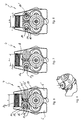
- the 6 and 7 show a plan view of the gripping device 4 Fig. 2 in partial section, with particular attention here on the readjustment of the centering 8 of the gripping arms 6 is located. Shown again are the over the bearing pin 16 on the (shown in section) central unit 18 pivotally arranged gripping arms 6. To ensure a uniform gripping movement of the gripping arms 6, as already mentioned, the gripping arms 6 coupled via a centering 8 with each other.
- the centering toothing 8 comprises two toothed elements 12, which are each arranged integrally on the gripping arms.
- the toothed elements 12 are here arranged concentrically to the axis of rotation A R of the gripping arms 6, so that upon rotation of the gripping arms 6 around the axis of rotation A R, the interlocking toothed elements 12 form a rotating rotational toothing 8.
- Fig. 6 Due to material abrasion occurs over time between these gear elements 12 to wear and so to a game within the centering 8. This is in Fig. 6 shown. To make up for this game has the here in Fig. 6 on the left representation plane gripper arm 6 an adjusting device 10, via which the operative engagement of the centering 8 is adjustable.
- the adjusting device 10 comprises an eccentric bearing cylinder 14, which is arranged on the bearing pin 16 and, upon rotation of the bearing pin 14 about its alignment axis A J , moves the toothed element 12 towards the complementary toothed element 12 '.
- the eccentric bearing cylinder 14 also acts here as a rotary bearing for the gripper arm 6, so that the axis of symmetry of the eccentric bearing cylinder 14, the cylinder axis A R , at the same time also forms the axis of rotation A R for the opening and closing movements of the gripping arm 6.
- Fig. 8 shows one to the in the 6 and 7 illustrated gripping device similar embodiment. However, here both gripping arms 6 adjusting devices 10, so that a uniform and in particular a twice as large displacement of the toothing elements of the centering 8 is possible.
- the bearing pin both in section ( Fig. 10 ) as well as in an isometry ( Fig. 11 ) or a partially cut isometry ( Fig. 12 ).
- Recognizable is the bearing pin head 22 and the Lagerbolzenfuss 24, between which the eccentric bearing cylinder 14 is arranged.
- the eccentricity between the adjusting axis A J and the axis of rotation A R , which corresponds to the cylinder axis of the eccentric bearing cylinder 14, is in particular in Fig. 10 recognizable.
- the part of the locking device 26 shown here comprises the locking element 28, which is formed as an outer 12-Kant and fit and rotationsarretierend in the Arret michsussielement 30 to the central unit 18 (see Fig. 4 ) intervenes. Due to the 12-edge shape of the bearing pin 16 can be locked in relatively small rotational steps. If even smaller locking steps are necessary, instead of a 12-edge, an outer n-edge with a higher edge number n, for example a 14-edge, can also be formed.
- an adjustment means 36 provided in the form of an inner hexagon, which allows the inclusion of a conventional Allen key and over which the bearing pin 16 is easily rotatable.
- a sliding friction between the adjusting means 36 and an inserted Allen key (not shown) beyond the bearing pin 16 is axially, ie parallel to the adjustment axis A J from the locking engagement between the locking element 28 and locking counter 30 (see Fig. 4 ), so that then an adjustment of the centering 8 (see Fig. 6-8 ) is vorrisebar.
- This condition is in Fig. 9 shown.
- the locking element 28 is compared to the bearing pin head 22 is very flat, so that the bearing pin 16 only slightly pushed out of its bearing pin receptacle 32 in order to release the locking engagement.
- Fig. 1 shown basic body 2 with corresponding access openings (not shown) to provide, via which the insertion of a Allen key or the like tool in the adjusting means 36 of the adjusting device 10 and the bearing pin 16 is possible.
- Such an access opening can preferably be designed so that the axial displacement of the position pin 16 for releasing the locking engagement and the subsequent adjustment is made possible without the gripping device 4 has to be removed from the base body 2.
- Fig. 12 the bearing pin 16 is shown in an isometric partial section. It can be seen here that both the bearing bolt head 22 and the bearing bolt foot 24 are arranged via fastening means 38, in this case screwed connections, on the eccentric bearing cylinder 14.
- fastening means 38 in this case screwed connections
- Such a multi-part design of the bearing pin 16 allows the replacement of any defective individual components and the adaptation of the eccentric bearing cylinder 14, the bearing pin head 22 and the Lagerbolzenfußes 24 as needed.
- Fig. 14 shows an isometric view of the bearing pin head 22 at the, for mounting on the eccentric bearing cylinder 14 (see Fig. 10-12 ) the fastening means 38 is integrally formed in the form of a screw bolt. Also shown is the locking element 28, which has the shape of an outer 12-Kant, in order to fix the bearing pin 16 rotationally locking in the central unit 18. Within the locking element 28 beyond the adjusting means 36, here as inner hexagon, formed.
- Fig. 15 the eccentric bearing cylinder 14 is arranged, wherein Fig. 16 a plan view of this eccentric bearing cylinder 14 shows. Visible is on the one hand a receptacle 39 in the form of a threaded bore for the fastening means 38 of the bearing pin head 22 and the other (in Fig. 16 ) to the adjustment axis A J of the bearing pin 16 eccentric arrangement of the cylinder axis of the eccentric bearing cylinder 14 and the axis of rotation A R.
- Fig. 17 the eccentric bearing cylinder 14 is shown in longitudinal section, again the eccentricity of the axes A R and A J and the receptacles 39 for the fastening means 38 of the bearing pin head 22 and the Lagerbolzenfußes 24 (see Fig. 18 ) are recognizable.
- This bearing pin 24 is isometric in Fig. 18 represented, wherein here, the integral formation of the fastening means 38 can be seen.
Priority Applications (5)
| Application Number | Priority Date | Filing Date | Title |
|---|---|---|---|
| DE502008001906T DE502008001906D1 (de) | 2008-09-02 | 2008-09-02 | Transportstern |
| ES08163531T ES2355091T3 (es) | 2008-09-02 | 2008-09-02 | Transportador en forma de estrella. |
| EP08163531A EP2159172B1 (fr) | 2008-09-02 | 2008-09-02 | Convoyeur de type caroussel |
| DK08163531.0T DK2159172T3 (da) | 2008-09-02 | 2008-09-02 | Transport-stjernehjul |
| AT08163531T ATE489314T1 (de) | 2008-09-02 | 2008-09-02 | Transportstern |
Applications Claiming Priority (1)
| Application Number | Priority Date | Filing Date | Title |
|---|---|---|---|
| EP08163531A EP2159172B1 (fr) | 2008-09-02 | 2008-09-02 | Convoyeur de type caroussel |
Publications (2)
| Publication Number | Publication Date |
|---|---|
| EP2159172A1 true EP2159172A1 (fr) | 2010-03-03 |
| EP2159172B1 EP2159172B1 (fr) | 2010-11-24 |
Family
ID=39929768
Family Applications (1)
| Application Number | Title | Priority Date | Filing Date |
|---|---|---|---|
| EP08163531A Active EP2159172B1 (fr) | 2008-09-02 | 2008-09-02 | Convoyeur de type caroussel |
Country Status (5)
| Country | Link |
|---|---|
| EP (1) | EP2159172B1 (fr) |
| AT (1) | ATE489314T1 (fr) |
| DE (1) | DE502008001906D1 (fr) |
| DK (1) | DK2159172T3 (fr) |
| ES (1) | ES2355091T3 (fr) |
Cited By (23)
| Publication number | Priority date | Publication date | Assignee | Title |
|---|---|---|---|---|
| WO2012069109A1 (fr) * | 2010-11-25 | 2012-05-31 | Khs Gmbh | Dispositif de préhension pour bouteilles en pet |
| WO2012123566A1 (fr) * | 2011-03-17 | 2012-09-20 | Sidel Participations | Dispositif de transfert comportant une pince de prehension |
| DE102012103114A1 (de) * | 2012-04-11 | 2013-10-17 | Krones Ag | Vorrichtung und Verfahren zum Halten von Behältnissen |
| US8813950B2 (en) | 2010-05-07 | 2014-08-26 | The Procter & Gamble Company | Automated adjustment system for star wheel |
| EP2769942A1 (fr) * | 2013-02-25 | 2014-08-27 | Tyrolon-Schulnig GmbH | Bras de préhension pour un dispositif de préhension ainsi que la machine pour transporter des récipients au moyen de ces bras de préhension |
| US8820514B2 (en) | 2010-05-07 | 2014-09-02 | The Procter & Gamble Company | Universally adjustable star wheel |
| EP2774878A1 (fr) * | 2013-03-08 | 2014-09-10 | Tyrolon-Schulnig GmbH | Bras de préhension pour un dispositif de préhension ainsi que la machine pour transporter des récipients au moyen de ces bras de préhension |
| EP2774876A1 (fr) * | 2013-03-06 | 2014-09-10 | Tyrolon-Schulnig GmbH | Dispositif de préhension destiné à saisir et à maintenir des bouteilles et dispositif de transport doté d'un tel dispositif de préhension |
| EP2876064A1 (fr) * | 2013-11-26 | 2015-05-27 | Sidel S.p.a. Con Socio Unico | Ligne de convoyage de récipients, en particulier de bouteilles |
| WO2015110858A1 (fr) * | 2014-01-27 | 2015-07-30 | Frank Liese | Élément de préhension pour dispositif de manipulation de récipients et système de transport en étoile |
| CN104860047A (zh) * | 2015-06-02 | 2015-08-26 | 吴江市七都镇庙港雅迪针织制衣厂 | 一种布料卷筒轴输送装置 |
| WO2016023741A3 (fr) * | 2014-08-13 | 2016-04-28 | Tyrolon-Schulnig Gmbh | Bras de préhension pour contenants, came de commande, unité d'appui et dispositif de préhension |
| DE102014116259A1 (de) | 2014-11-07 | 2016-05-12 | Khs Gmbh | Transportstern für den Transport von Behältern |
| CN107161670A (zh) * | 2017-06-20 | 2017-09-15 | 安徽普伦智能装备有限公司 | 一种定位运输卸料装置 |
| CN107399601A (zh) * | 2017-03-03 | 2017-11-28 | 广东省智能制造研究所 | 一种物料姿态转换机构 |
| EP2949608B1 (fr) * | 2014-05-28 | 2018-06-13 | Tyrolon-Schulnig GmbH | Bras de préhension pour récipient, dispositif préhenseur et dispositif de transport |
| WO2018162153A1 (fr) * | 2017-03-09 | 2018-09-13 | Tyrolon-Schulnig Gmbh | Ensemble palier |
| WO2018162096A1 (fr) * | 2017-03-09 | 2018-09-13 | Tyrolon-Schulnig Gmbh | Dispositif de support et arbre à cames pour dispositifs de préhension |
| WO2019161979A1 (fr) | 2018-02-23 | 2019-08-29 | Khs Gmbh | Grappin pour un système de transport de contenants |
| CN110869297A (zh) * | 2017-07-10 | 2020-03-06 | 大日本印刷株式会社 | 搬送装置、调整旋转搬送部及搬送方法 |
| EP3825265A1 (fr) * | 2019-11-22 | 2021-05-26 | Krones AG | Dispositif de serrage permettant de maintenir un récipient |
| USD944877S1 (en) * | 2017-03-09 | 2022-03-01 | Tyrolon-Schulnig Gmbh | Filling machine for bottles |
| IT202100028028A1 (it) * | 2021-11-03 | 2023-05-03 | Sidel Participations Sas | Pinza per afferrare e trattenere contenitori adatti ad essere riempiti con un prodotto versabile |
Families Citing this family (2)
| Publication number | Priority date | Publication date | Assignee | Title |
|---|---|---|---|---|
| DE202015105481U1 (de) | 2015-10-16 | 2017-01-17 | Krones Ag | Vorrichtung zum Transportieren und bodenseitigen Etikettieren von Behältern |
| DE102018121092A1 (de) * | 2018-08-29 | 2020-03-05 | Khs Gmbh | Vorrichtung zum Greifen von Behältern |
Citations (7)
| Publication number | Priority date | Publication date | Assignee | Title |
|---|---|---|---|---|
| US2788818A (en) | 1950-12-14 | 1957-04-16 | Special Equipment Co | Peach feeding, orienting, assorting, transferring, splitting, and pitting machine |
| EP0659683A1 (fr) * | 1993-12-24 | 1995-06-28 | I.M.A. INDUSTRIA MACCHINE AUTOMATICHE S.p.A. | Machine automatique pour remplir et fermer des flacons ou récipients similaires |
| DE29602798U1 (de) | 1996-02-16 | 1996-09-19 | Kronseder Maschf Krones | Transportstern für Gefäße |
| DE29607868U1 (de) | 1996-04-30 | 1997-06-05 | Kronseder Maschf Krones | Transportstern für Gefäß |
| US5711411A (en) * | 1995-11-13 | 1998-01-27 | Lever Brothers Company, Division Of Conopco, Inc. | Quick changeover filling, centering bracket |
| DE20305988U1 (de) | 2003-04-14 | 2003-07-03 | Tyrolon Schulnig Ges M B H | Transportstern |
| WO2003078285A1 (fr) * | 2002-03-18 | 2003-09-25 | S.I.P.A. Societa' Industrializzazione Progettazione E Automazione S.P.A. | Systeme de prehension pour bouteilles et analogue |
-
2008
- 2008-09-02 DE DE502008001906T patent/DE502008001906D1/de active Active
- 2008-09-02 ES ES08163531T patent/ES2355091T3/es active Active
- 2008-09-02 AT AT08163531T patent/ATE489314T1/de active
- 2008-09-02 DK DK08163531.0T patent/DK2159172T3/da active
- 2008-09-02 EP EP08163531A patent/EP2159172B1/fr active Active
Patent Citations (7)
| Publication number | Priority date | Publication date | Assignee | Title |
|---|---|---|---|---|
| US2788818A (en) | 1950-12-14 | 1957-04-16 | Special Equipment Co | Peach feeding, orienting, assorting, transferring, splitting, and pitting machine |
| EP0659683A1 (fr) * | 1993-12-24 | 1995-06-28 | I.M.A. INDUSTRIA MACCHINE AUTOMATICHE S.p.A. | Machine automatique pour remplir et fermer des flacons ou récipients similaires |
| US5711411A (en) * | 1995-11-13 | 1998-01-27 | Lever Brothers Company, Division Of Conopco, Inc. | Quick changeover filling, centering bracket |
| DE29602798U1 (de) | 1996-02-16 | 1996-09-19 | Kronseder Maschf Krones | Transportstern für Gefäße |
| DE29607868U1 (de) | 1996-04-30 | 1997-06-05 | Kronseder Maschf Krones | Transportstern für Gefäß |
| WO2003078285A1 (fr) * | 2002-03-18 | 2003-09-25 | S.I.P.A. Societa' Industrializzazione Progettazione E Automazione S.P.A. | Systeme de prehension pour bouteilles et analogue |
| DE20305988U1 (de) | 2003-04-14 | 2003-07-03 | Tyrolon Schulnig Ges M B H | Transportstern |
Cited By (40)
| Publication number | Priority date | Publication date | Assignee | Title |
|---|---|---|---|---|
| US8813950B2 (en) | 2010-05-07 | 2014-08-26 | The Procter & Gamble Company | Automated adjustment system for star wheel |
| US9340364B2 (en) | 2010-05-07 | 2016-05-17 | The Procter & Gamble Company | Automated adjustment system for star wheel |
| US8820514B2 (en) | 2010-05-07 | 2014-09-02 | The Procter & Gamble Company | Universally adjustable star wheel |
| US8894114B2 (en) | 2010-11-25 | 2014-11-25 | Khs Gmbh | PET bottle gripping device |
| WO2012069109A1 (fr) * | 2010-11-25 | 2012-05-31 | Khs Gmbh | Dispositif de préhension pour bouteilles en pet |
| WO2012123566A1 (fr) * | 2011-03-17 | 2012-09-20 | Sidel Participations | Dispositif de transfert comportant une pince de prehension |
| FR2972671A1 (fr) * | 2011-03-17 | 2012-09-21 | Sidel Participations | Dispositif de transfert comportant une pince de prehension perfectionnee |
| US9022442B2 (en) | 2011-03-17 | 2015-05-05 | Sidel Participations | Transfer device comprising a gripper |
| DE102012103114A1 (de) * | 2012-04-11 | 2013-10-17 | Krones Ag | Vorrichtung und Verfahren zum Halten von Behältnissen |
| CN104003185B (zh) * | 2013-02-25 | 2017-03-01 | 图洛龙-斯楚林有限公司 | 用于夹持装置的夹持臂 |
| CN104003185A (zh) * | 2013-02-25 | 2014-08-27 | 图洛龙-斯楚林有限公司 | 用于夹持装置的夹持臂 |
| US9193538B2 (en) | 2013-02-25 | 2015-11-24 | Tyrolon-Schulnig Gmbh | Gripping arm for a gripper device |
| EP2769942A1 (fr) * | 2013-02-25 | 2014-08-27 | Tyrolon-Schulnig GmbH | Bras de préhension pour un dispositif de préhension ainsi que la machine pour transporter des récipients au moyen de ces bras de préhension |
| EP2774876A1 (fr) * | 2013-03-06 | 2014-09-10 | Tyrolon-Schulnig GmbH | Dispositif de préhension destiné à saisir et à maintenir des bouteilles et dispositif de transport doté d'un tel dispositif de préhension |
| EP2774878A1 (fr) * | 2013-03-08 | 2014-09-10 | Tyrolon-Schulnig GmbH | Bras de préhension pour un dispositif de préhension ainsi que la machine pour transporter des récipients au moyen de ces bras de préhension |
| EP2876064A1 (fr) * | 2013-11-26 | 2015-05-27 | Sidel S.p.a. Con Socio Unico | Ligne de convoyage de récipients, en particulier de bouteilles |
| ITTO20130960A1 (it) * | 2013-11-26 | 2015-05-27 | Sidel Spa Con Socio Unico | Linea per il convogliamento di contenitori, in particolare bottiglie |
| WO2015110858A1 (fr) * | 2014-01-27 | 2015-07-30 | Frank Liese | Élément de préhension pour dispositif de manipulation de récipients et système de transport en étoile |
| EP2949608B1 (fr) * | 2014-05-28 | 2018-06-13 | Tyrolon-Schulnig GmbH | Bras de préhension pour récipient, dispositif préhenseur et dispositif de transport |
| WO2016023741A3 (fr) * | 2014-08-13 | 2016-04-28 | Tyrolon-Schulnig Gmbh | Bras de préhension pour contenants, came de commande, unité d'appui et dispositif de préhension |
| DE102014111564B4 (de) * | 2014-08-13 | 2021-04-01 | Tyrolon-Schulnig Gmbh | Greifarm für Behälter, Steuernocken, Lagereinheit und Greifeinrichtung |
| DE102014116259A1 (de) | 2014-11-07 | 2016-05-12 | Khs Gmbh | Transportstern für den Transport von Behältern |
| CN104860047B (zh) * | 2015-06-02 | 2017-04-05 | 海安纺织机械有限公司 | 一种布料卷筒轴输送装置 |
| CN104860047A (zh) * | 2015-06-02 | 2015-08-26 | 吴江市七都镇庙港雅迪针织制衣厂 | 一种布料卷筒轴输送装置 |
| CN107399601A (zh) * | 2017-03-03 | 2017-11-28 | 广东省智能制造研究所 | 一种物料姿态转换机构 |
| USD944877S1 (en) * | 2017-03-09 | 2022-03-01 | Tyrolon-Schulnig Gmbh | Filling machine for bottles |
| US10669107B2 (en) | 2017-03-09 | 2020-06-02 | Tyrolon-Schulnig Gmbh | Carrying apparatus and cam control shaft for gripping devices |
| WO2018162096A1 (fr) * | 2017-03-09 | 2018-09-13 | Tyrolon-Schulnig Gmbh | Dispositif de support et arbre à cames pour dispositifs de préhension |
| WO2018162153A1 (fr) * | 2017-03-09 | 2018-09-13 | Tyrolon-Schulnig Gmbh | Ensemble palier |
| CN107161670A (zh) * | 2017-06-20 | 2017-09-15 | 安徽普伦智能装备有限公司 | 一种定位运输卸料装置 |
| CN107161670B (zh) * | 2017-06-20 | 2019-02-15 | 安徽普伦智能装备有限公司 | 一种定位运输卸料装置 |
| CN110869297A (zh) * | 2017-07-10 | 2020-03-06 | 大日本印刷株式会社 | 搬送装置、调整旋转搬送部及搬送方法 |
| CN110869297B (zh) * | 2017-07-10 | 2021-06-04 | 大日本印刷株式会社 | 搬送装置、调整旋转搬送部及搬送方法 |
| DE102018104112A1 (de) * | 2018-02-23 | 2019-08-29 | Khs Gmbh | Greifer für ein Behältertransportsystem |
| WO2019161979A1 (fr) | 2018-02-23 | 2019-08-29 | Khs Gmbh | Grappin pour un système de transport de contenants |
| US11866271B2 (en) | 2018-02-23 | 2024-01-09 | Khs Gmbh | Gripper for a container transport system |
| EP3825265A1 (fr) * | 2019-11-22 | 2021-05-26 | Krones AG | Dispositif de serrage permettant de maintenir un récipient |
| US11802035B2 (en) | 2019-11-22 | 2023-10-31 | Krones Ag | Clamping device for holding a container |
| IT202100028028A1 (it) * | 2021-11-03 | 2023-05-03 | Sidel Participations Sas | Pinza per afferrare e trattenere contenitori adatti ad essere riempiti con un prodotto versabile |
| WO2023078629A1 (fr) * | 2021-11-03 | 2023-05-11 | Sidel Participations | Dispositif de préhension pour la préhension et le maintien de contenants conçus pour être remplis d'un produit pouvant être versé |
Also Published As
| Publication number | Publication date |
|---|---|
| DK2159172T3 (da) | 2011-03-07 |
| ATE489314T1 (de) | 2010-12-15 |
| ES2355091T3 (es) | 2011-03-22 |
| EP2159172B1 (fr) | 2010-11-24 |
| DE502008001906D1 (de) | 2011-01-05 |
Similar Documents
| Publication | Publication Date | Title |
|---|---|---|
| EP2159172B1 (fr) | Convoyeur de type caroussel | |
| EP0743267B1 (fr) | Roue convoyeuse à étoile pour récipients | |
| DE2102412C3 (de) | Verstellvorrichtung an Kurbelwellenschleifmaschinen zum Ausrichten der zu schleifenden Kurbelzapfen | |
| EP2962675B1 (fr) | Pied pour table d'opération | |
| EP2343255A1 (fr) | Dispositif de saisie pour une roue convoyeuse à étoile et roue convoyeuse à étoile | |
| EP0248917A1 (fr) | Dispositif de réglage de la course du coulisseau dans une presse à arbre à excentrique | |
| DE3923230A1 (de) | Werkzeugmaschine mit einem drehtisch und drehbaren halteeinrichtungen | |
| WO2019161422A1 (fr) | Support pour moule à immersion | |
| EP3025974A1 (fr) | Disque d'appui destine a etre utilise dans des dispositifs de traitement de recipient et/ou d'installation | |
| DE1527181B1 (de) | Gewindebohrmaschine | |
| CH616109A5 (fr) | ||
| DE3001271A1 (de) | Zufuehrungseinrichtung vom walzentyp zum zufuehren von flaechigem material | |
| EP2241441A1 (fr) | Dispositif de traitement d'un matériau en bande entre deux cylindres de travail pouvant être entraînés de manière opposée | |
| EP0406808B1 (fr) | Commande à bielle pour un alimentateur de flans, en particulier pour une machine à découper ou à cintrer automatique | |
| EP2886224B1 (fr) | Tête à rouler les filets | |
| DE60203593T2 (de) | Falzklappenzylinder mit einer Einstellung der zeitlichen Steuerung in der Falzvorrichtung einer Rollenrotationsdruckmaschine | |
| DE202013003913U1 (de) | Plattenbearbeitungsanlage mit gebremstem Werkstückauflagetisch | |
| EP0810175B1 (fr) | Dispositif de mise en précontrainte d'un mécanisme d'application d'un couple sur un cylindre de pliage | |
| DE2148801B2 (de) | Abhebeeinrichtung für das Schneidrad einer Zahnradwälzstoßmaschine | |
| DE102013006606A1 (de) | Werkzeugwechsler | |
| DE4211101C2 (de) | Axialverriegelungseinrichtung | |
| DE3151737A1 (de) | Zangenarmaufbau | |
| DE2413035A1 (de) | Antriebsvorrichtung fuer eine gewindewalzmaschine | |
| EP0362477B1 (fr) | Système d'étirage pour un métier à filer | |
| DE912696C (de) | Adressier- oder aehnliche Druckmaschine |
Legal Events
| Date | Code | Title | Description |
|---|---|---|---|
| PUAI | Public reference made under article 153(3) epc to a published international application that has entered the european phase |
Free format text: ORIGINAL CODE: 0009012 |
|
| 17P | Request for examination filed |
Effective date: 20090318 |
|
| AK | Designated contracting states |
Kind code of ref document: A1 Designated state(s): AT BE BG CH CY CZ DE DK EE ES FI FR GB GR HR HU IE IS IT LI LT LU LV MC MT NL NO PL PT RO SE SI SK TR |
|
| AX | Request for extension of the european patent |
Extension state: AL BA MK RS |
|
| GRAP | Despatch of communication of intention to grant a patent |
Free format text: ORIGINAL CODE: EPIDOSNIGR1 |
|
| GRAS | Grant fee paid |
Free format text: ORIGINAL CODE: EPIDOSNIGR3 |
|
| RAP1 | Party data changed (applicant data changed or rights of an application transferred) |
Owner name: TYROLON-SCHULNIG GMBH |
|
| GRAA | (expected) grant |
Free format text: ORIGINAL CODE: 0009210 |
|
| AKX | Designation fees paid |
Designated state(s): AT BE BG CH CY CZ DE DK EE ES FI FR GB GR HR HU IE IS IT LI LT LU LV MC MT NL NO PL PT RO SE SI SK TR |
|
| AK | Designated contracting states |
Kind code of ref document: B1 Designated state(s): AT BE BG CH CY CZ DE DK EE ES FI FR GB GR HR HU IE IS IT LI LT LU LV MC MT NL NO PL PT RO SE SI SK TR |
|
| REG | Reference to a national code |
Ref country code: GB Ref legal event code: FG4D Free format text: NOT ENGLISH |
|
| REG | Reference to a national code |
Ref country code: CH Ref legal event code: EP |
|
| REG | Reference to a national code |
Ref country code: IE Ref legal event code: FG4D |
|
| REF | Corresponds to: |
Ref document number: 502008001906 Country of ref document: DE Date of ref document: 20110105 Kind code of ref document: P |
|
| REG | Reference to a national code |
Ref country code: CH Ref legal event code: NV Representative=s name: FIAMMENGHI-FIAMMENGHI |
|
| REG | Reference to a national code |
Ref country code: NL Ref legal event code: T3 |
|
| REG | Reference to a national code |
Ref country code: DK Ref legal event code: T3 |
|
| REG | Reference to a national code |
Ref country code: ES Ref legal event code: FG2A Effective date: 20110310 |
|
| LTIE | Lt: invalidation of european patent or patent extension |
Effective date: 20101124 |
|
| PG25 | Lapsed in a contracting state [announced via postgrant information from national office to epo] |
Ref country code: LT Free format text: LAPSE BECAUSE OF FAILURE TO SUBMIT A TRANSLATION OF THE DESCRIPTION OR TO PAY THE FEE WITHIN THE PRESCRIBED TIME-LIMIT Effective date: 20101124 Ref country code: NO Free format text: LAPSE BECAUSE OF FAILURE TO SUBMIT A TRANSLATION OF THE DESCRIPTION OR TO PAY THE FEE WITHIN THE PRESCRIBED TIME-LIMIT Effective date: 20110224 |
|
| PG25 | Lapsed in a contracting state [announced via postgrant information from national office to epo] |
Ref country code: CY Free format text: LAPSE BECAUSE OF FAILURE TO SUBMIT A TRANSLATION OF THE DESCRIPTION OR TO PAY THE FEE WITHIN THE PRESCRIBED TIME-LIMIT Effective date: 20101124 Ref country code: HR Free format text: LAPSE BECAUSE OF FAILURE TO SUBMIT A TRANSLATION OF THE DESCRIPTION OR TO PAY THE FEE WITHIN THE PRESCRIBED TIME-LIMIT Effective date: 20101124 Ref country code: IS Free format text: LAPSE BECAUSE OF FAILURE TO SUBMIT A TRANSLATION OF THE DESCRIPTION OR TO PAY THE FEE WITHIN THE PRESCRIBED TIME-LIMIT Effective date: 20110324 Ref country code: FI Free format text: LAPSE BECAUSE OF FAILURE TO SUBMIT A TRANSLATION OF THE DESCRIPTION OR TO PAY THE FEE WITHIN THE PRESCRIBED TIME-LIMIT Effective date: 20101124 Ref country code: LV Free format text: LAPSE BECAUSE OF FAILURE TO SUBMIT A TRANSLATION OF THE DESCRIPTION OR TO PAY THE FEE WITHIN THE PRESCRIBED TIME-LIMIT Effective date: 20101124 Ref country code: BG Free format text: LAPSE BECAUSE OF FAILURE TO SUBMIT A TRANSLATION OF THE DESCRIPTION OR TO PAY THE FEE WITHIN THE PRESCRIBED TIME-LIMIT Effective date: 20110224 Ref country code: SI Free format text: LAPSE BECAUSE OF FAILURE TO SUBMIT A TRANSLATION OF THE DESCRIPTION OR TO PAY THE FEE WITHIN THE PRESCRIBED TIME-LIMIT Effective date: 20101124 Ref country code: SE Free format text: LAPSE BECAUSE OF FAILURE TO SUBMIT A TRANSLATION OF THE DESCRIPTION OR TO PAY THE FEE WITHIN THE PRESCRIBED TIME-LIMIT Effective date: 20101124 Ref country code: PT Free format text: LAPSE BECAUSE OF FAILURE TO SUBMIT A TRANSLATION OF THE DESCRIPTION OR TO PAY THE FEE WITHIN THE PRESCRIBED TIME-LIMIT Effective date: 20110324 |
|
| REG | Reference to a national code |
Ref country code: IE Ref legal event code: FD4D |
|
| PG25 | Lapsed in a contracting state [announced via postgrant information from national office to epo] |
Ref country code: GR Free format text: LAPSE BECAUSE OF FAILURE TO SUBMIT A TRANSLATION OF THE DESCRIPTION OR TO PAY THE FEE WITHIN THE PRESCRIBED TIME-LIMIT Effective date: 20110225 |
|
| PG25 | Lapsed in a contracting state [announced via postgrant information from national office to epo] |
Ref country code: EE Free format text: LAPSE BECAUSE OF FAILURE TO SUBMIT A TRANSLATION OF THE DESCRIPTION OR TO PAY THE FEE WITHIN THE PRESCRIBED TIME-LIMIT Effective date: 20101124 Ref country code: IE Free format text: LAPSE BECAUSE OF FAILURE TO SUBMIT A TRANSLATION OF THE DESCRIPTION OR TO PAY THE FEE WITHIN THE PRESCRIBED TIME-LIMIT Effective date: 20101124 Ref country code: CZ Free format text: LAPSE BECAUSE OF FAILURE TO SUBMIT A TRANSLATION OF THE DESCRIPTION OR TO PAY THE FEE WITHIN THE PRESCRIBED TIME-LIMIT Effective date: 20101124 |
|
| PG25 | Lapsed in a contracting state [announced via postgrant information from national office to epo] |
Ref country code: RO Free format text: LAPSE BECAUSE OF FAILURE TO SUBMIT A TRANSLATION OF THE DESCRIPTION OR TO PAY THE FEE WITHIN THE PRESCRIBED TIME-LIMIT Effective date: 20101124 Ref country code: PL Free format text: LAPSE BECAUSE OF FAILURE TO SUBMIT A TRANSLATION OF THE DESCRIPTION OR TO PAY THE FEE WITHIN THE PRESCRIBED TIME-LIMIT Effective date: 20101124 Ref country code: SK Free format text: LAPSE BECAUSE OF FAILURE TO SUBMIT A TRANSLATION OF THE DESCRIPTION OR TO PAY THE FEE WITHIN THE PRESCRIBED TIME-LIMIT Effective date: 20101124 |
|
| PLBE | No opposition filed within time limit |
Free format text: ORIGINAL CODE: 0009261 |
|
| STAA | Information on the status of an ep patent application or granted ep patent |
Free format text: STATUS: NO OPPOSITION FILED WITHIN TIME LIMIT |
|
| 26N | No opposition filed |
Effective date: 20110825 |
|
| REG | Reference to a national code |
Ref country code: DE Ref legal event code: R097 Ref document number: 502008001906 Country of ref document: DE Effective date: 20110825 |
|
| PG25 | Lapsed in a contracting state [announced via postgrant information from national office to epo] |
Ref country code: MC Free format text: LAPSE BECAUSE OF NON-PAYMENT OF DUE FEES Effective date: 20110930 |
|
| PG25 | Lapsed in a contracting state [announced via postgrant information from national office to epo] |
Ref country code: MT Free format text: LAPSE BECAUSE OF FAILURE TO SUBMIT A TRANSLATION OF THE DESCRIPTION OR TO PAY THE FEE WITHIN THE PRESCRIBED TIME-LIMIT Effective date: 20101124 |
|
| PG25 | Lapsed in a contracting state [announced via postgrant information from national office to epo] |
Ref country code: LU Free format text: LAPSE BECAUSE OF NON-PAYMENT OF DUE FEES Effective date: 20110902 |
|
| PG25 | Lapsed in a contracting state [announced via postgrant information from national office to epo] |
Ref country code: TR Free format text: LAPSE BECAUSE OF FAILURE TO SUBMIT A TRANSLATION OF THE DESCRIPTION OR TO PAY THE FEE WITHIN THE PRESCRIBED TIME-LIMIT Effective date: 20101124 |
|
| PG25 | Lapsed in a contracting state [announced via postgrant information from national office to epo] |
Ref country code: HU Free format text: LAPSE BECAUSE OF FAILURE TO SUBMIT A TRANSLATION OF THE DESCRIPTION OR TO PAY THE FEE WITHIN THE PRESCRIBED TIME-LIMIT Effective date: 20101124 |
|
| REG | Reference to a national code |
Ref country code: FR Ref legal event code: PLFP Year of fee payment: 9 |
|
| REG | Reference to a national code |
Ref country code: FR Ref legal event code: PLFP Year of fee payment: 10 |
|
| REG | Reference to a national code |
Ref country code: FR Ref legal event code: PLFP Year of fee payment: 11 |
|
| PGFP | Annual fee paid to national office [announced via postgrant information from national office to epo] |
Ref country code: DK Payment date: 20190924 Year of fee payment: 12 Ref country code: NL Payment date: 20190926 Year of fee payment: 12 |
|
| PGFP | Annual fee paid to national office [announced via postgrant information from national office to epo] |
Ref country code: BE Payment date: 20190926 Year of fee payment: 12 |
|
| REG | Reference to a national code |
Ref country code: DK Ref legal event code: EBP Effective date: 20200930 |
|
| REG | Reference to a national code |
Ref country code: NL Ref legal event code: MM Effective date: 20201001 |
|
| REG | Reference to a national code |
Ref country code: BE Ref legal event code: MM Effective date: 20200930 |
|
| PG25 | Lapsed in a contracting state [announced via postgrant information from national office to epo] |
Ref country code: NL Free format text: LAPSE BECAUSE OF NON-PAYMENT OF DUE FEES Effective date: 20201001 |
|
| PG25 | Lapsed in a contracting state [announced via postgrant information from national office to epo] |
Ref country code: BE Free format text: LAPSE BECAUSE OF NON-PAYMENT OF DUE FEES Effective date: 20200930 |
|
| PG25 | Lapsed in a contracting state [announced via postgrant information from national office to epo] |
Ref country code: DK Free format text: LAPSE BECAUSE OF NON-PAYMENT OF DUE FEES Effective date: 20200930 |
|
| PGFP | Annual fee paid to national office [announced via postgrant information from national office to epo] |
Ref country code: CH Payment date: 20220928 Year of fee payment: 15 |
|
| PGFP | Annual fee paid to national office [announced via postgrant information from national office to epo] |
Ref country code: IT Payment date: 20230920 Year of fee payment: 16 Ref country code: GB Payment date: 20230926 Year of fee payment: 16 Ref country code: AT Payment date: 20230919 Year of fee payment: 16 |
|
| PGFP | Annual fee paid to national office [announced via postgrant information from national office to epo] |
Ref country code: FR Payment date: 20230926 Year of fee payment: 16 Ref country code: DE Payment date: 20230929 Year of fee payment: 16 |
|
| PGFP | Annual fee paid to national office [announced via postgrant information from national office to epo] |
Ref country code: ES Payment date: 20231017 Year of fee payment: 16 |
|
| REG | Reference to a national code |
Ref country code: CH Ref legal event code: PL |