EP2159094B1 - Structure de transmission pour véhicule - Google Patents
Structure de transmission pour véhicule Download PDFInfo
- Publication number
- EP2159094B1 EP2159094B1 EP09168816A EP09168816A EP2159094B1 EP 2159094 B1 EP2159094 B1 EP 2159094B1 EP 09168816 A EP09168816 A EP 09168816A EP 09168816 A EP09168816 A EP 09168816A EP 2159094 B1 EP2159094 B1 EP 2159094B1
- Authority
- EP
- European Patent Office
- Prior art keywords
- travel
- rearward
- shaft
- unit
- clutch
- Prior art date
- Legal status (The legal status is an assumption and is not a legal conclusion. Google has not performed a legal analysis and makes no representation as to the accuracy of the status listed.)
- Active
Links
- 230000005540 biological transmission Effects 0.000 title claims description 185
- 239000012530 fluid Substances 0.000 claims description 262
- 239000000314 lubricant Substances 0.000 claims description 172
- 230000007246 mechanism Effects 0.000 claims description 37
- 230000002093 peripheral effect Effects 0.000 claims description 25
- 230000004308 accommodation Effects 0.000 claims description 12
- 230000004048 modification Effects 0.000 description 28
- 238000012986 modification Methods 0.000 description 28
- 239000000969 carrier Substances 0.000 description 11
- 230000007935 neutral effect Effects 0.000 description 11
- 230000001965 increasing effect Effects 0.000 description 9
- 238000010586 diagram Methods 0.000 description 8
- 230000009467 reduction Effects 0.000 description 8
- 238000004519 manufacturing process Methods 0.000 description 6
- 238000007599 discharging Methods 0.000 description 3
- 238000006073 displacement reaction Methods 0.000 description 3
- 230000033001 locomotion Effects 0.000 description 3
- 238000000034 method Methods 0.000 description 3
- 238000012544 monitoring process Methods 0.000 description 2
- 238000005299 abrasion Methods 0.000 description 1
- 230000000903 blocking effect Effects 0.000 description 1
- 230000008859 change Effects 0.000 description 1
- 230000007547 defect Effects 0.000 description 1
- 238000001514 detection method Methods 0.000 description 1
- 230000002708 enhancing effect Effects 0.000 description 1
- 238000003825 pressing Methods 0.000 description 1
- 238000011144 upstream manufacturing Methods 0.000 description 1
Images


Classifications
-
- F—MECHANICAL ENGINEERING; LIGHTING; HEATING; WEAPONS; BLASTING
- F16—ENGINEERING ELEMENTS AND UNITS; GENERAL MEASURES FOR PRODUCING AND MAINTAINING EFFECTIVE FUNCTIONING OF MACHINES OR INSTALLATIONS; THERMAL INSULATION IN GENERAL
- F16H—GEARING
- F16H37/00—Combinations of mechanical gearings, not provided for in groups F16H1/00 - F16H35/00
- F16H37/02—Combinations of mechanical gearings, not provided for in groups F16H1/00 - F16H35/00 comprising essentially only toothed or friction gearings
-
- F—MECHANICAL ENGINEERING; LIGHTING; HEATING; WEAPONS; BLASTING
- F16—ENGINEERING ELEMENTS AND UNITS; GENERAL MEASURES FOR PRODUCING AND MAINTAINING EFFECTIVE FUNCTIONING OF MACHINES OR INSTALLATIONS; THERMAL INSULATION IN GENERAL
- F16H—GEARING
- F16H47/00—Combinations of mechanical gearing with fluid clutches or fluid gearing
- F16H47/02—Combinations of mechanical gearing with fluid clutches or fluid gearing the fluid gearing being of the volumetric type
- F16H47/04—Combinations of mechanical gearing with fluid clutches or fluid gearing the fluid gearing being of the volumetric type the mechanical gearing being of the type with members having orbital motion
-
- F—MECHANICAL ENGINEERING; LIGHTING; HEATING; WEAPONS; BLASTING
- F16—ENGINEERING ELEMENTS AND UNITS; GENERAL MEASURES FOR PRODUCING AND MAINTAINING EFFECTIVE FUNCTIONING OF MACHINES OR INSTALLATIONS; THERMAL INSULATION IN GENERAL
- F16H—GEARING
- F16H1/00—Toothed gearings for conveying rotary motion
- F16H1/28—Toothed gearings for conveying rotary motion with gears having orbital motion
- F16H1/46—Systems consisting of a plurality of gear trains each with orbital gears, i.e. systems having three or more central gears
-
- F—MECHANICAL ENGINEERING; LIGHTING; HEATING; WEAPONS; BLASTING
- F16—ENGINEERING ELEMENTS AND UNITS; GENERAL MEASURES FOR PRODUCING AND MAINTAINING EFFECTIVE FUNCTIONING OF MACHINES OR INSTALLATIONS; THERMAL INSULATION IN GENERAL
- F16H—GEARING
- F16H57/00—General details of gearing
- F16H57/02—Gearboxes; Mounting gearing therein
- F16H57/021—Shaft support structures, e.g. partition walls, bearing eyes, casing walls or covers with bearings
-
- B—PERFORMING OPERATIONS; TRANSPORTING
- B60—VEHICLES IN GENERAL
- B60K—ARRANGEMENT OR MOUNTING OF PROPULSION UNITS OR OF TRANSMISSIONS IN VEHICLES; ARRANGEMENT OR MOUNTING OF PLURAL DIVERSE PRIME-MOVERS IN VEHICLES; AUXILIARY DRIVES FOR VEHICLES; INSTRUMENTATION OR DASHBOARDS FOR VEHICLES; ARRANGEMENTS IN CONNECTION WITH COOLING, AIR INTAKE, GAS EXHAUST OR FUEL SUPPLY OF PROPULSION UNITS IN VEHICLES
- B60K17/00—Arrangement or mounting of transmissions in vehicles
- B60K17/28—Arrangement or mounting of transmissions in vehicles characterised by arrangement, location, or type of power take-off
-
- F—MECHANICAL ENGINEERING; LIGHTING; HEATING; WEAPONS; BLASTING
- F16—ENGINEERING ELEMENTS AND UNITS; GENERAL MEASURES FOR PRODUCING AND MAINTAINING EFFECTIVE FUNCTIONING OF MACHINES OR INSTALLATIONS; THERMAL INSULATION IN GENERAL
- F16H—GEARING
- F16H37/00—Combinations of mechanical gearings, not provided for in groups F16H1/00 - F16H35/00
- F16H37/02—Combinations of mechanical gearings, not provided for in groups F16H1/00 - F16H35/00 comprising essentially only toothed or friction gearings
- F16H37/06—Combinations of mechanical gearings, not provided for in groups F16H1/00 - F16H35/00 comprising essentially only toothed or friction gearings with a plurality of driving or driven shafts; with arrangements for dividing torque between two or more intermediate shafts
- F16H37/08—Combinations of mechanical gearings, not provided for in groups F16H1/00 - F16H35/00 comprising essentially only toothed or friction gearings with a plurality of driving or driven shafts; with arrangements for dividing torque between two or more intermediate shafts with differential gearing
- F16H37/0833—Combinations of mechanical gearings, not provided for in groups F16H1/00 - F16H35/00 comprising essentially only toothed or friction gearings with a plurality of driving or driven shafts; with arrangements for dividing torque between two or more intermediate shafts with differential gearing with arrangements for dividing torque between two or more intermediate shafts, i.e. with two or more internal power paths
- F16H37/084—Combinations of mechanical gearings, not provided for in groups F16H1/00 - F16H35/00 comprising essentially only toothed or friction gearings with a plurality of driving or driven shafts; with arrangements for dividing torque between two or more intermediate shafts with differential gearing with arrangements for dividing torque between two or more intermediate shafts, i.e. with two or more internal power paths at least one power path being a continuously variable transmission, i.e. CVT
- F16H2037/088—Power split variators with summing differentials, with the input of the CVT connected or connectable to the input shaft
- F16H2037/0886—Power split variators with summing differentials, with the input of the CVT connected or connectable to the input shaft with switching means, e.g. to change ranges
-
- F—MECHANICAL ENGINEERING; LIGHTING; HEATING; WEAPONS; BLASTING
- F16—ENGINEERING ELEMENTS AND UNITS; GENERAL MEASURES FOR PRODUCING AND MAINTAINING EFFECTIVE FUNCTIONING OF MACHINES OR INSTALLATIONS; THERMAL INSULATION IN GENERAL
- F16H—GEARING
- F16H57/00—General details of gearing
- F16H57/02—Gearboxes; Mounting gearing therein
- F16H2057/02039—Gearboxes for particular applications
- F16H2057/02043—Gearboxes for particular applications for vehicle transmissions
Landscapes
- Engineering & Computer Science (AREA)
- General Engineering & Computer Science (AREA)
- Mechanical Engineering (AREA)
- General Details Of Gearings (AREA)
- Motor Power Transmission Devices (AREA)
- Arrangement Of Transmissions (AREA)
- Structure Of Transmissions (AREA)
- Retarders (AREA)
- Hydraulic Clutches, Magnetic Clutches, Fluid Clutches, And Fluid Joints (AREA)
Claims (7)
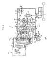
- Structure de transmission d'un système de déplacement pour véhicule comprenant un bloc d'engrenages planétaires (40, 40B) ayant un premier composant et un second composant destinés respectivement à recevoir une énergie rotationnelle à vitesse constante et une énergie rotationnelle à vitesse variable et ayant également un troisième composant pour l'émission d'une énergie rotationnelle combinée formée en combinant les énergies rotationnelles des premier et second composants, une unité de commutateur de course (50, 50B) qui reçoit de manière opérationnelle l'énergie rotationnelle combinée émise depuis le troisième composant, et un carter de transmission (62, 62B) qui héberge le bloc d'engrenages planétaires et l'unité de commutateur de course avant/arrière, la structure de transmission d'un système de déplacement étant caractérisée par le fait que
le carter de transmission a une ouverture frontale (62F) qui est fournie sur une face frontale et a une taille telle qu'elle permet au bloc d'engrenages planétaires d'être inséré à travers cette ouverture, une ouverture arrière (62R) qui est fournie sur une face arrière et a une taille telle qu'elle permet à l'unité de commutateur de course avant/arrière d'être insérée à travers cette ouverture, une paroi porteuse intermédiaire (602, 602B) qui est fournie au niveau d'une portion intermédiaire dans une direction d'avant en arrière,
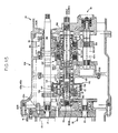
le bloc d'engrenages planétaires a un arbre de roue solaire (141, 660) qui supporte une roue solaire (42) d'une manière relativement non rotationnelle par rapport à celui-ci, la roue solaire fonctionnant comme un des premier et second composants, et un élément de sortie planétaire (142, 670) qui est relié au troisième composant d'une manière relativement non rotationnelle par rapport à celui-ci autour de la ligne d'axe du bloc d'engrenages planétaires,
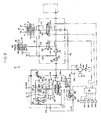
l'unité de commutateur de course avant/arrière a un arbre d'entrée de course avant/arrière (51, 510) qui reçoit de manière opérationnelle l'énergie rotationnelle combinée, un arbre de sortie de course avant/arrière (52, 520) qui transmet l'énergie rotationnelle à une unité de course, un mécanisme d'embrayage de course avant/arrière (53, 55, 530) apte à changer la direction rotationnelle de l'énergie rotationnelle transmise de l'arbre d'entrée de course avant/arrière à l'arbre de sortie de course avant/arrière, et un arbre d'embrayage (51, 560) qui est disposé de manière coaxiale avec l'arbre d'entrée de course avant/arrière et supporte le mécanisme d'embrayage de course avant/arrière,
une partie d'extrémité frontale de l'arbre de roue solaire est soutenue directement ou indirectement de manière rotative autour de la ligne d'axe par une paroi porteuse frontale (601, 601B) qui est reliée de manière détachable à une face frontale du carter de transmission et une partie d'extrémité arrière de l'élément de sortie planétaire est soutenue directement ou indirectement de manière rotative autour de la ligne d'axe par la paroi porteuse intermédiaire, de telle sorte que le bloc d'engrenages planétaires est hébergé dans une chambre frontale qui est intercalée entre la paroi porteuse frontale et la paroi porteuse intermédiaire,
une partie d'extrémité frontale de l'arbre d'entrée de course avant/arrière est soutenue directement ou indirectement par la paroi porteuse intermédiaire de manière rotative autour de la ligne d'axe dans un état dans lequel elle est raccordée à l'élément de sortie planétaire de manière à être relativement non-rotative par rapport à celui-ci autour de la ligne d'axe et une partie d'extrémité arrière de l'arbre d'embrayage est soutenue de manière rotative autour de la ligne d'axe par une paroi porteuse arrière (603, 603B) qui est reliée de manière détachable à la face arrière du carter de transmission, de telle sorte que l'unité de commutation de course avant/arrière est hébergée dans une chambre arrière qui est intercalée entre la paroi porteuse intermédiaire et la paroi porteuse arrière. - Structure de transmission d'un système de déplacement pour véhicule selon la revendication 1, dans laquelle
l'arbre de sortie planétaire a une partie de raccordement (143) raccordée au troisième composant, et une portion cylindrique creuse (145) qui s'étend de la partie de raccordement à l'unité de commutation de course avant/arrière et est directement ou indirectement soutenue par la paroi porteuse intermédiaire,
la partie d'extrémité frontale de l'arbre d'entrée de course avant/arrière est installée dans la portion cylindrique depuis la face arrière de la portion cylindrique de manière à être relativement non-rotative par rapport à celle-ci autour de la ligne d'axe, et
l'arbre de roue solaire a une partie d'extrémité arrière qui est insérée dans la portion cylindrique depuis la face frontale de la portion cylindrique de manière à être en regard avec l'arbre d'entrée de course avant/arrière et est soutenu par la portion cylindrique d'une manière relativement rotative par rapport à celui-ci autour de la ligne d'axe. - Structure de transmission d'un système de déplacement pour véhicule selon la revendication 2, dans laquelle
le mécanisme d'embrayage de course avant/arrière est un mécanisme d'embrayage de type hydraulique,
l'arbre d'embrayage est formé d'une amenée de fluide lubrifiant de course avant/arrière (430e, 580) destinée à guider le fluide lubrifiant d'une source du fluide vers le mécanisme d'embrayage de course avant/arrière,
l'arbre d'entrée de course avant/arrière est formé d'une conduite de raccordement de fluide lubrifiant (581) qui a une extrémité frontale au niveau de la surface d'extrémité frontale de l'arbre d'entrée de course avant/arrière à l'intérieur de la portion cylindrique dans un état dans lequel elle est raccordée de façon fluide avec l'amenée de fluide lubrifiant de course avant/arrière,
l'arbre de roue solaire est formé d'une conduite d'introduction de fluide lubrifiant (582) qui a une extrémité arrière ouverte à la surface d'extrémité arrière de l'arbre de roue solaire à l'intérieur de la portion cylindrique, et le fluide lubrifiant est introduit depuis l'extrémité frontale de la conduite de raccordement de fluide lubrifiant vers l'extrémité arrière de la conduite d'introduction de fluide lubrifiant à travers la portion cylindrique. - Structure de transmission d'un système de déplacement pour véhicule selon la revendication 3, dans laquelle
l'arbre d'entrée de course avant/arrière et l'arbre d'embrayage sont formés intégralement en un seul tenant par un arbre unique (570),
la paroi porteuse intermédiaire comprend une région de soutien côté bloc d'engrenages planétaires (602B(1)) qui soutient la portion cylindrique par l'intermédiaire d'un élément porteur (147a), une région de soutien côté unité de commutateur de course avant/arrière (602B(3)) qui soutient l'arbre unique par l'intermédiaire d'un élément porteur (571a), et une région intermédiaire (602B(2)) qui est située entre la région de soutien côté bloc d'engrenages planétaires et la région de soutien côté unité de commutateur de course avant/arrière, et
la région intermédiaire est formée d'un joint rotatif de lubrifiant de course avant/arrière (578) qui raccorde de manière fluide une conduite de fluide lubrifiant de course avant/arrière côté paroi porteuse intermédiaire (575), qui est formée dans la paroi porteuse intermédiaire, avec l'amenée de fluide lubrifiant de course avant/arrière ou la conduite de raccordement de fluide lubrifiant. - Structure de transmission d'un système de déplacement pour véhicule selon la revendication 3 ou 4, dans laquelle
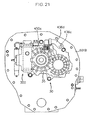
le bloc d'engrenages planétaires a un support (41) qui soutient un engrenage planétaire (45), qui vient en prise avec la roue solaire de manière rotative autour de la ligne d'axe et tourne autour de la roue solaire conjointement avec l'engrenage planétaire, le support fonctionnant comme un des premier au troisième composants ; un engrenage interne (43) qui est pourvu d'une denture interne en prise avec l'engrenage planétaire et fonctionne comme un autre des premier à troisième composants ; un élément de soutien du support (700) qui soutient le support de manière à pouvoir entrer en rotation autour de la roue solaire conjointement avec le support 41 ; et un engrenage d'entrée d'énergie rotationnelle (44, 44B) qui est relié soit à l'élément de soutien du support soit à l'engrenage interne de manière à transmettre l'énergie rotationnelle à vitesse constante ou l'énergie rotationnelle à vitesse variable au même élément de soutien du support ou engrenage interne, l'engrenage d'entrée d'énergie rotationnel étant soutenu par l'arbre de roue solaire de manière relativement rotationnelle par rapport à celui-ci,
l'élément de soutien de support a une paroi frontale (710) qui est pourvue d'un trou de soutien frontal (711) destiné à soutenir une extrémité frontale du support et une ouverture centrale (712) destinée à permettre à l'arbre de roue solaire d'y être inséré, une paroi arrière (720) qui est pourvue d'un trou de soutien arrière (721) destiné à soutenir l'extrémité arrière du support et une ouverture centrale (722) destinée à permettre à l'arbre de roue solaire d'y être insérée, et une partie de raccordement (730) destinée à raccorder la paroi frontale avec la paroi arrière,
un espace de poche de fluide (585) est au moins fourni soit entre la paroi frontale et l'engrenage d'entrée d'énergie rotationnel, soit entre la paroi arrière et l'élément de sortie planétaire de manière à s'étendre radialement avec l'arbre de roue solaire comme référence, l'espace de poche de fluide ayant une partie radialement interne ouverte vers la surface extérieure périphérique de l'arbre de roue solaire et une partie radialement externe ouverte vers l'extrémité correspondante du support,
l'arbre de roue solaire est formée d'une conduite de distribution de fluide lubrifiant de support (583d) qui a une première extrémité raccordée de manière fluide à la conduite d'introduction de fluide lubrifiant et une seconde extrémité ouverte au niveau de la surface périphérique extérieure de l'arbre de roue solaire de manière à être dirigée vers l'espace de poche de fluide, et
le support est formé d'une conduite d'introduction de fluide lubrifiant d'engrenage planétaire (586) ayant une première extrémité ouverte au niveau d'une extrémité du support qui est en regard de l'espace de poche de fluide et une seconde extrémité ouverte au niveau de la surface extérieure d'une zone du support qui soutient l'engrenage planétaire. - Structure de transmission d'un système de déplacement pour véhicule selon la revendication 5, dans laquelle la portion radialement interne de l'espace de poche de fluide est ouverte vers la surface périphérique extérieure de l'arbre de roue solaire sur une zone entière dans une direction circonférentielle.
- Structure de transmission d'un système de déplacement pour véhicule selon la revendication 5 ou 6, dans laquelle
la paroi frontale, la paroi arrière et la partie de raccordement sont formées intégralement en un seul tenant de telle sorte que l'élément de soutien du support a un espace d'hébergement de l'engrenage planétaire qui est intercalé entre la paroi frontale et la paroi arrière et est situé dans une position correspondant au trou de soutien frontal et au trou de soutien arrière dans la direction circonférentielle, et
l'espace d'hébergement de l'engrenage planétaire a une partie radialement interne ouverte vers l'intérieur de manière à permettre à l'engrenage planétaire de venir en prise avec la roue solaire, et une partie radialement externe ouverte vers l'extérieur de manière à permettre à l'engrenage planétaire d'être inséré radialement à partir de l'extérieur dans l'espace d'hébergement de l'engrenage planétaire.
Priority Applications (1)
| Application Number | Priority Date | Filing Date | Title |
|---|---|---|---|
| EP11153197A EP2319720B1 (fr) | 2008-08-29 | 2009-08-27 | Structure de transmission pour véhicule |
Applications Claiming Priority (2)
| Application Number | Priority Date | Filing Date | Title |
|---|---|---|---|
| JP2008221672 | 2008-08-29 | ||
| JP2009149356A JP2010076748A (ja) | 2008-08-29 | 2009-06-24 | 車輌の走行系伝動構造 |
Related Child Applications (2)
| Application Number | Title | Priority Date | Filing Date |
|---|---|---|---|
| EP11153197A Division EP2319720B1 (fr) | 2008-08-29 | 2009-08-27 | Structure de transmission pour véhicule |
| EP11153197.6 Division-Into | 2011-02-03 |
Publications (3)
| Publication Number | Publication Date |
|---|---|
| EP2159094A2 EP2159094A2 (fr) | 2010-03-03 |
| EP2159094A3 EP2159094A3 (fr) | 2010-03-17 |
| EP2159094B1 true EP2159094B1 (fr) | 2012-07-25 |
Family
ID=41228847
Family Applications (2)
| Application Number | Title | Priority Date | Filing Date |
|---|---|---|---|
| EP09168816A Active EP2159094B1 (fr) | 2008-08-29 | 2009-08-27 | Structure de transmission pour véhicule |
| EP11153197A Active EP2319720B1 (fr) | 2008-08-29 | 2009-08-27 | Structure de transmission pour véhicule |
Family Applications After (1)
| Application Number | Title | Priority Date | Filing Date |
|---|---|---|---|
| EP11153197A Active EP2319720B1 (fr) | 2008-08-29 | 2009-08-27 | Structure de transmission pour véhicule |
Country Status (4)
| Country | Link |
|---|---|
| US (1) | US8337353B2 (fr) |
| EP (2) | EP2159094B1 (fr) |
| JP (1) | JP2010076748A (fr) |
| KR (1) | KR20100026975A (fr) |
Families Citing this family (23)
| Publication number | Priority date | Publication date | Assignee | Title |
|---|---|---|---|---|
| DE102009002808A1 (de) * | 2009-05-05 | 2010-11-11 | Zf Friedrichshafen Ag | Antriebsstrang eines Nutzfahrzeugs umfassend ein Stufenlos-Getriebe |
| WO2012011662A2 (fr) * | 2010-07-19 | 2012-01-26 | Shin Young-Chul | Transmission à variation continue |
| KR101327332B1 (ko) | 2011-04-07 | 2013-11-08 | 신현우 | 허브타입의 무단변속장치 |
| EP2618027B1 (fr) * | 2010-09-14 | 2019-05-22 | Kubota Corporation | Dispositif de transmission pour un tracteur |
| WO2013165491A1 (fr) * | 2012-05-02 | 2013-11-07 | Parker-Hannifin Corporation | Engrenages de lubrification par projection et système de lubrification |
| JP2014008951A (ja) * | 2012-07-03 | 2014-01-20 | Kanzaki Kokyukoki Mfg Co Ltd | 作業車両の走行変速制御機構 |
| EP2954226B1 (fr) | 2013-02-11 | 2018-08-08 | DANA ITALIA S.p.A | Transmission hydrostatique et à entraînement direct |
| US9186987B2 (en) | 2013-12-10 | 2015-11-17 | Borgwarner, Inc. | Electro-mechanical transfer case with range shift on the move |
| JP6381418B2 (ja) | 2013-12-10 | 2018-08-29 | ボーグワーナー インコーポレーテッド | 同心性の作動を有するモータ駆動型トランスファケース |
| DE102015214871A1 (de) * | 2014-08-07 | 2016-02-11 | Kanzaki Kokyukoki Mfg. Co., Ltd. | Steuermechanismus für ein hydrostatisches Getriebe |
| JP6335728B2 (ja) * | 2014-09-09 | 2018-05-30 | ヤンマー株式会社 | 作業車両 |
| JP6335727B2 (ja) * | 2014-09-09 | 2018-05-30 | ヤンマー株式会社 | 作業車両 |
| JP6329863B2 (ja) * | 2014-09-09 | 2018-05-23 | ヤンマー株式会社 | 作業車両 |
| JP6439995B2 (ja) * | 2014-10-31 | 2018-12-26 | 愛知機械工業株式会社 | 変速機ケースおよびこれを備える変速機 |
| EP3299669B1 (fr) * | 2015-05-18 | 2023-02-01 | Yanmar Power Technology Co., Ltd. | Transmission |
| JP2017031897A (ja) * | 2015-08-03 | 2017-02-09 | 株式会社クボタ | 作業車 |
| DE102016212209A1 (de) * | 2016-07-05 | 2018-01-11 | Zf Friedrichshafen Ag | Nebenabtriebsanordnung |
| KR102530334B1 (ko) | 2018-05-29 | 2023-05-08 | 엘에스엠트론 주식회사 | 유압 트랜스미션 조립체 |
| CN114222877B (zh) | 2019-08-15 | 2024-04-26 | 株式会社神崎高级工机制作所 | 变速器构造 |
| EP3798468A3 (fr) * | 2019-09-26 | 2021-10-06 | Kubota Corporation | Dispositif de transmission d'entraînement de tracteur |
| DE102019219356A1 (de) * | 2019-12-11 | 2021-06-17 | Zf Friedrichshafen Ag | Leistungsverzweigungsgetriebe und Antriebsstrang für eine Arbeitsmaschine |
| CN111271430A (zh) * | 2020-02-13 | 2020-06-12 | 山东省农业机械科学研究院 | 一种机械液压耦合传动无级变速箱及传动系统及拖拉机 |
| JP2022156638A (ja) | 2021-03-31 | 2022-10-14 | 株式会社 神崎高級工機製作所 | 油圧・機械式無段変速装置 |
Family Cites Families (13)
| Publication number | Priority date | Publication date | Assignee | Title |
|---|---|---|---|---|
| JP2586607Y2 (ja) * | 1992-06-17 | 1998-12-09 | ジャトコ株式会社 | 遊星歯車装置 |
| JP3939871B2 (ja) * | 1998-12-22 | 2007-07-04 | 株式会社 神崎高級工機製作所 | 車両用の走行変速制御装置 |
| JP2002079839A (ja) * | 2000-09-07 | 2002-03-19 | Kanzaki Kokyukoki Mfg Co Ltd | 作業車両のトランスミッション |
| JP3868257B2 (ja) | 2001-10-22 | 2007-01-17 | ヤンマー農機株式会社 | 作業車両の変速装置 |
| JP4067310B2 (ja) * | 2002-01-17 | 2008-03-26 | ヤンマー農機株式会社 | 田植機 |
| JP2003276461A (ja) * | 2002-01-18 | 2003-09-30 | Kanzaki Kokyukoki Mfg Co Ltd | 作業車輌 |
| DE102004016242A1 (de) * | 2004-04-02 | 2005-10-20 | Deere & Co | Antriebssystem eines Arbeitsfahrzeugs |
| KR101390761B1 (ko) * | 2005-07-19 | 2014-04-30 | 얀마 가부시키가이샤 | 트랜스미션 |
| EP1961994A3 (fr) * | 2007-01-23 | 2010-08-25 | Kanzaki Kokyukoki Mfg. Co., Ltd. | Système de transmission pour véhicule de chantier |
| JP5027521B2 (ja) * | 2007-02-05 | 2012-09-19 | 株式会社クボタ | 変速伝動装置 |
| KR101143062B1 (ko) * | 2007-02-05 | 2012-05-11 | 가부시끼 가이샤 구보다 | 변속 전동 장치 |
| JP2008202721A (ja) * | 2007-02-21 | 2008-09-04 | Yanmar Co Ltd | トランスミッション |
| JP2008208912A (ja) * | 2007-02-26 | 2008-09-11 | Kanzaki Kokyukoki Mfg Co Ltd | 作業車用変速機構 |
-
2009
- 2009-06-24 JP JP2009149356A patent/JP2010076748A/ja active Pending
- 2009-07-27 KR KR1020090068483A patent/KR20100026975A/ko not_active Application Discontinuation
- 2009-08-27 US US12/549,077 patent/US8337353B2/en active Active
- 2009-08-27 EP EP09168816A patent/EP2159094B1/fr active Active
- 2009-08-27 EP EP11153197A patent/EP2319720B1/fr active Active
Also Published As
| Publication number | Publication date |
|---|---|
| EP2319720B1 (fr) | 2012-10-17 |
| EP2319720A1 (fr) | 2011-05-11 |
| EP2159094A2 (fr) | 2010-03-03 |
| EP2159094A3 (fr) | 2010-03-17 |
| KR20100026975A (ko) | 2010-03-10 |
| JP2010076748A (ja) | 2010-04-08 |
| US20100051410A1 (en) | 2010-03-04 |
| US8337353B2 (en) | 2012-12-25 |
Similar Documents
| Publication | Publication Date | Title |
|---|---|---|
| EP2159094B1 (fr) | Structure de transmission pour véhicule | |
| KR101020410B1 (ko) | 변속 동력 전달 장치 | |
| US6176802B1 (en) | Vehicular automatic transmission | |
| US8210977B2 (en) | Hydraulic control device of automatic transmission | |
| US6543311B1 (en) | Driving system for industrial trucks | |
| JP2008189144A (ja) | 変速伝動装置 | |
| JP2000355225A (ja) | 作業車両のトランスミッション | |
| JP7300713B2 (ja) | トランスミッション構造及び作業車輌 | |
| US20070123386A1 (en) | Traveling System Auxiliary Speed Change Device | |
| JP2000351332A (ja) | 車輌の走行用トランスミッション | |
| JP2009078699A (ja) | 作業車の走行伝動構造 | |
| JP5426731B2 (ja) | 作業車両の変速装置 | |
| JP5592539B2 (ja) | 作業車両の変速装置 | |
| JP4106252B2 (ja) | 二輪・四輪駆動切換機構 | |
| JP5346456B2 (ja) | 作業車両の変速装置 | |
| JP2002192972A (ja) | 作業機の走行用伝動装置 | |
| JP2008195334A (ja) | 変速伝動装置 | |
| JP5065810B2 (ja) | 変速伝動装置 | |
| KR102583451B1 (ko) | Pto 유압 제어 밸브 장치 | |
| JP4106234B2 (ja) | 四輪駆動・前輪増速駆動切換機構 | |
| JP4981463B2 (ja) | 作業車の走行伝動構造 | |
| JP4162302B2 (ja) | 作業車両におけるデフロック操作装置 | |
| JP4899752B2 (ja) | 走行車両 | |
| JP3773830B2 (ja) | 作業車両の非常用走行機構 | |
| JP3616575B2 (ja) | 作業車両の走行装置 |
Legal Events
| Date | Code | Title | Description |
|---|---|---|---|
| PUAI | Public reference made under article 153(3) epc to a published international application that has entered the european phase |
Free format text: ORIGINAL CODE: 0009012 |
|
| PUAL | Search report despatched |
Free format text: ORIGINAL CODE: 0009013 |
|
| AK | Designated contracting states |
Kind code of ref document: A2 Designated state(s): AT BE BG CH CY CZ DE DK EE ES FI FR GB GR HR HU IE IS IT LI LT LU LV MC MK MT NL NO PL PT RO SE SI SK SM TR |
|
| AX | Request for extension of the european patent |
Extension state: AL BA RS |
|
| AK | Designated contracting states |
Kind code of ref document: A3 Designated state(s): AT BE BG CH CY CZ DE DK EE ES FI FR GB GR HR HU IE IS IT LI LT LU LV MC MK MT NL NO PL PT RO SE SI SK SM TR |
|
| AX | Request for extension of the european patent |
Extension state: AL BA RS |
|
| RIC1 | Information provided on ipc code assigned before grant |
Ipc: B60W 10/10 20060101ALI20100211BHEP Ipc: B60W 10/18 20060101ALI20100211BHEP Ipc: B60K 17/04 20060101AFI20091202BHEP Ipc: F16H 47/04 20060101ALI20100211BHEP Ipc: B60K 17/28 20060101ALI20100211BHEP |
|
| 17P | Request for examination filed |
Effective date: 20100714 |
|
| 17Q | First examination report despatched |
Effective date: 20100816 |
|
| GRAP | Despatch of communication of intention to grant a patent |
Free format text: ORIGINAL CODE: EPIDOSNIGR1 |
|
| GRAS | Grant fee paid |
Free format text: ORIGINAL CODE: EPIDOSNIGR3 |
|
| GRAA | (expected) grant |
Free format text: ORIGINAL CODE: 0009210 |
|
| AK | Designated contracting states |
Kind code of ref document: B1 Designated state(s): AT BE BG CH CY CZ DE DK EE ES FI FR GB GR HR HU IE IS IT LI LT LU LV MC MK MT NL NO PL PT RO SE SI SK SM TR |
|
| REG | Reference to a national code |
Ref country code: GB Ref legal event code: FG4D |
|
| REG | Reference to a national code |
Ref country code: CH Ref legal event code: EP |
|
| REG | Reference to a national code |
Ref country code: AT Ref legal event code: REF Ref document number: 567552 Country of ref document: AT Kind code of ref document: T Effective date: 20120815 Ref country code: IE Ref legal event code: FG4D |
|
| REG | Reference to a national code |
Ref country code: DE Ref legal event code: R096 Ref document number: 602009008445 Country of ref document: DE Effective date: 20120920 |
|
| REG | Reference to a national code |
Ref country code: NL Ref legal event code: VDEP Effective date: 20120725 |
|
| REG | Reference to a national code |
Ref country code: AT Ref legal event code: MK05 Ref document number: 567552 Country of ref document: AT Kind code of ref document: T Effective date: 20120725 |
|
| REG | Reference to a national code |
Ref country code: LT Ref legal event code: MG4D Effective date: 20120725 |
|
| PGFP | Annual fee paid to national office [announced via postgrant information from national office to epo] |
Ref country code: FR Payment date: 20120906 Year of fee payment: 4 |
|
| PG25 | Lapsed in a contracting state [announced via postgrant information from national office to epo] |
Ref country code: AT Free format text: LAPSE BECAUSE OF FAILURE TO SUBMIT A TRANSLATION OF THE DESCRIPTION OR TO PAY THE FEE WITHIN THE PRESCRIBED TIME-LIMIT Effective date: 20120725 Ref country code: CY Free format text: LAPSE BECAUSE OF FAILURE TO SUBMIT A TRANSLATION OF THE DESCRIPTION OR TO PAY THE FEE WITHIN THE PRESCRIBED TIME-LIMIT Effective date: 20120725 Ref country code: IS Free format text: LAPSE BECAUSE OF FAILURE TO SUBMIT A TRANSLATION OF THE DESCRIPTION OR TO PAY THE FEE WITHIN THE PRESCRIBED TIME-LIMIT Effective date: 20121125 Ref country code: FI Free format text: LAPSE BECAUSE OF FAILURE TO SUBMIT A TRANSLATION OF THE DESCRIPTION OR TO PAY THE FEE WITHIN THE PRESCRIBED TIME-LIMIT Effective date: 20120725 Ref country code: HR Free format text: LAPSE BECAUSE OF FAILURE TO SUBMIT A TRANSLATION OF THE DESCRIPTION OR TO PAY THE FEE WITHIN THE PRESCRIBED TIME-LIMIT Effective date: 20120725 Ref country code: LT Free format text: LAPSE BECAUSE OF FAILURE TO SUBMIT A TRANSLATION OF THE DESCRIPTION OR TO PAY THE FEE WITHIN THE PRESCRIBED TIME-LIMIT Effective date: 20120725 Ref country code: NO Free format text: LAPSE BECAUSE OF FAILURE TO SUBMIT A TRANSLATION OF THE DESCRIPTION OR TO PAY THE FEE WITHIN THE PRESCRIBED TIME-LIMIT Effective date: 20121025 Ref country code: BE Free format text: LAPSE BECAUSE OF FAILURE TO SUBMIT A TRANSLATION OF THE DESCRIPTION OR TO PAY THE FEE WITHIN THE PRESCRIBED TIME-LIMIT Effective date: 20120725 |
|
| PG25 | Lapsed in a contracting state [announced via postgrant information from national office to epo] |
Ref country code: PT Free format text: LAPSE BECAUSE OF FAILURE TO SUBMIT A TRANSLATION OF THE DESCRIPTION OR TO PAY THE FEE WITHIN THE PRESCRIBED TIME-LIMIT Effective date: 20121126 Ref country code: PL Free format text: LAPSE BECAUSE OF FAILURE TO SUBMIT A TRANSLATION OF THE DESCRIPTION OR TO PAY THE FEE WITHIN THE PRESCRIBED TIME-LIMIT Effective date: 20120725 Ref country code: SE Free format text: LAPSE BECAUSE OF FAILURE TO SUBMIT A TRANSLATION OF THE DESCRIPTION OR TO PAY THE FEE WITHIN THE PRESCRIBED TIME-LIMIT Effective date: 20120725 Ref country code: SI Free format text: LAPSE BECAUSE OF FAILURE TO SUBMIT A TRANSLATION OF THE DESCRIPTION OR TO PAY THE FEE WITHIN THE PRESCRIBED TIME-LIMIT Effective date: 20120725 Ref country code: LV Free format text: LAPSE BECAUSE OF FAILURE TO SUBMIT A TRANSLATION OF THE DESCRIPTION OR TO PAY THE FEE WITHIN THE PRESCRIBED TIME-LIMIT Effective date: 20120725 Ref country code: GR Free format text: LAPSE BECAUSE OF FAILURE TO SUBMIT A TRANSLATION OF THE DESCRIPTION OR TO PAY THE FEE WITHIN THE PRESCRIBED TIME-LIMIT Effective date: 20121026 |
|
| PGFP | Annual fee paid to national office [announced via postgrant information from national office to epo] |
Ref country code: IT Payment date: 20120831 Year of fee payment: 4 |
|
| PG25 | Lapsed in a contracting state [announced via postgrant information from national office to epo] |
Ref country code: MC Free format text: LAPSE BECAUSE OF NON-PAYMENT OF DUE FEES Effective date: 20120831 Ref country code: NL Free format text: LAPSE BECAUSE OF FAILURE TO SUBMIT A TRANSLATION OF THE DESCRIPTION OR TO PAY THE FEE WITHIN THE PRESCRIBED TIME-LIMIT Effective date: 20120725 |
|
| PG25 | Lapsed in a contracting state [announced via postgrant information from national office to epo] |
Ref country code: DK Free format text: LAPSE BECAUSE OF FAILURE TO SUBMIT A TRANSLATION OF THE DESCRIPTION OR TO PAY THE FEE WITHIN THE PRESCRIBED TIME-LIMIT Effective date: 20120725 Ref country code: RO Free format text: LAPSE BECAUSE OF FAILURE TO SUBMIT A TRANSLATION OF THE DESCRIPTION OR TO PAY THE FEE WITHIN THE PRESCRIBED TIME-LIMIT Effective date: 20120725 Ref country code: EE Free format text: LAPSE BECAUSE OF FAILURE TO SUBMIT A TRANSLATION OF THE DESCRIPTION OR TO PAY THE FEE WITHIN THE PRESCRIBED TIME-LIMIT Effective date: 20120725 Ref country code: ES Free format text: LAPSE BECAUSE OF FAILURE TO SUBMIT A TRANSLATION OF THE DESCRIPTION OR TO PAY THE FEE WITHIN THE PRESCRIBED TIME-LIMIT Effective date: 20121105 Ref country code: CZ Free format text: LAPSE BECAUSE OF FAILURE TO SUBMIT A TRANSLATION OF THE DESCRIPTION OR TO PAY THE FEE WITHIN THE PRESCRIBED TIME-LIMIT Effective date: 20120725 |
|
| REG | Reference to a national code |
Ref country code: IE Ref legal event code: MM4A |
|
| PG25 | Lapsed in a contracting state [announced via postgrant information from national office to epo] |
Ref country code: SK Free format text: LAPSE BECAUSE OF FAILURE TO SUBMIT A TRANSLATION OF THE DESCRIPTION OR TO PAY THE FEE WITHIN THE PRESCRIBED TIME-LIMIT Effective date: 20120725 |
|
| PLBE | No opposition filed within time limit |
Free format text: ORIGINAL CODE: 0009261 |
|
| STAA | Information on the status of an ep patent application or granted ep patent |
Free format text: STATUS: NO OPPOSITION FILED WITHIN TIME LIMIT |
|
| 26N | No opposition filed |
Effective date: 20130426 |
|
| PG25 | Lapsed in a contracting state [announced via postgrant information from national office to epo] |
Ref country code: IE Free format text: LAPSE BECAUSE OF NON-PAYMENT OF DUE FEES Effective date: 20120827 Ref country code: BG Free format text: LAPSE BECAUSE OF FAILURE TO SUBMIT A TRANSLATION OF THE DESCRIPTION OR TO PAY THE FEE WITHIN THE PRESCRIBED TIME-LIMIT Effective date: 20121025 |
|
| REG | Reference to a national code |
Ref country code: DE Ref legal event code: R097 Ref document number: 602009008445 Country of ref document: DE Effective date: 20130426 |
|
| PG25 | Lapsed in a contracting state [announced via postgrant information from national office to epo] |
Ref country code: MT Free format text: LAPSE BECAUSE OF FAILURE TO SUBMIT A TRANSLATION OF THE DESCRIPTION OR TO PAY THE FEE WITHIN THE PRESCRIBED TIME-LIMIT Effective date: 20120725 |
|
| REG | Reference to a national code |
Ref country code: CH Ref legal event code: PL |
|
| GBPC | Gb: european patent ceased through non-payment of renewal fee |
Effective date: 20130827 |
|
| PG25 | Lapsed in a contracting state [announced via postgrant information from national office to epo] |
Ref country code: CH Free format text: LAPSE BECAUSE OF NON-PAYMENT OF DUE FEES Effective date: 20130831 Ref country code: TR Free format text: LAPSE BECAUSE OF FAILURE TO SUBMIT A TRANSLATION OF THE DESCRIPTION OR TO PAY THE FEE WITHIN THE PRESCRIBED TIME-LIMIT Effective date: 20120725 Ref country code: LI Free format text: LAPSE BECAUSE OF NON-PAYMENT OF DUE FEES Effective date: 20130831 |
|
| REG | Reference to a national code |
Ref country code: FR Ref legal event code: ST Effective date: 20140430 |
|
| PG25 | Lapsed in a contracting state [announced via postgrant information from national office to epo] |
Ref country code: LU Free format text: LAPSE BECAUSE OF NON-PAYMENT OF DUE FEES Effective date: 20120827 Ref country code: IT Free format text: LAPSE BECAUSE OF NON-PAYMENT OF DUE FEES Effective date: 20130827 Ref country code: SM Free format text: LAPSE BECAUSE OF FAILURE TO SUBMIT A TRANSLATION OF THE DESCRIPTION OR TO PAY THE FEE WITHIN THE PRESCRIBED TIME-LIMIT Effective date: 20120725 |
|
| PG25 | Lapsed in a contracting state [announced via postgrant information from national office to epo] |
Ref country code: GB Free format text: LAPSE BECAUSE OF NON-PAYMENT OF DUE FEES Effective date: 20130827 Ref country code: HU Free format text: LAPSE BECAUSE OF FAILURE TO SUBMIT A TRANSLATION OF THE DESCRIPTION OR TO PAY THE FEE WITHIN THE PRESCRIBED TIME-LIMIT Effective date: 20090827 |
|
| PG25 | Lapsed in a contracting state [announced via postgrant information from national office to epo] |
Ref country code: FR Free format text: LAPSE BECAUSE OF NON-PAYMENT OF DUE FEES Effective date: 20130902 |
|
| PG25 | Lapsed in a contracting state [announced via postgrant information from national office to epo] |
Ref country code: MK Free format text: LAPSE BECAUSE OF FAILURE TO SUBMIT A TRANSLATION OF THE DESCRIPTION OR TO PAY THE FEE WITHIN THE PRESCRIBED TIME-LIMIT Effective date: 20120725 |
|
| PGFP | Annual fee paid to national office [announced via postgrant information from national office to epo] |
Ref country code: DE Payment date: 20230821 Year of fee payment: 15 |