EP2154589A2 - Vorrichtung zur Optimierung der Bearbeitungsparameter, Verfahren zur Optimierung der Bearbeitungsparameter und Programm dafür - Google Patents
Vorrichtung zur Optimierung der Bearbeitungsparameter, Verfahren zur Optimierung der Bearbeitungsparameter und Programm dafür Download PDFInfo
- Publication number
- EP2154589A2 EP2154589A2 EP09166624A EP09166624A EP2154589A2 EP 2154589 A2 EP2154589 A2 EP 2154589A2 EP 09166624 A EP09166624 A EP 09166624A EP 09166624 A EP09166624 A EP 09166624A EP 2154589 A2 EP2154589 A2 EP 2154589A2
- Authority
- EP
- European Patent Office
- Prior art keywords
- machining
- deciding
- zone
- tooling
- tool
- Prior art date
- Legal status (The legal status is an assumption and is not a legal conclusion. Google has not performed a legal analysis and makes no representation as to the accuracy of the status listed.)
- Granted
Links
Images





Classifications
-
- G—PHYSICS
- G05—CONTROLLING; REGULATING
- G05B—CONTROL OR REGULATING SYSTEMS IN GENERAL; FUNCTIONAL ELEMENTS OF SUCH SYSTEMS; MONITORING OR TESTING ARRANGEMENTS FOR SUCH SYSTEMS OR ELEMENTS
- G05B19/00—Program-control systems
- G05B19/02—Program-control systems electric
- G05B19/18—Numerical control [NC], i.e. automatically operating machines, in particular machine tools, e.g. in a manufacturing environment, so as to execute positioning, movement or co-ordinated operations by means of program data in numerical form
- G05B19/4093—Numerical control [NC], i.e. automatically operating machines, in particular machine tools, e.g. in a manufacturing environment, so as to execute positioning, movement or co-ordinated operations by means of program data in numerical form characterised by part programming, e.g. entry of geometrical information as taken from a technical drawing, combining this with machining and material information to obtain control information, named part program, for the NC machine
- G05B19/40937—Numerical control [NC], i.e. automatically operating machines, in particular machine tools, e.g. in a manufacturing environment, so as to execute positioning, movement or co-ordinated operations by means of program data in numerical form characterised by part programming, e.g. entry of geometrical information as taken from a technical drawing, combining this with machining and material information to obtain control information, named part program, for the NC machine concerning programming of machining or material parameters, pocket machining
-
- G—PHYSICS
- G05—CONTROLLING; REGULATING
- G05B—CONTROL OR REGULATING SYSTEMS IN GENERAL; FUNCTIONAL ELEMENTS OF SUCH SYSTEMS; MONITORING OR TESTING ARRANGEMENTS FOR SUCH SYSTEMS OR ELEMENTS
- G05B2219/00—Program-control systems
- G05B2219/30—Nc systems
- G05B2219/35—Nc in input of data, input till input file format
- G05B2219/35316—Interference checking between tool, machine, part, chuck, machining range
-
- G—PHYSICS
- G05—CONTROLLING; REGULATING
- G05B—CONTROL OR REGULATING SYSTEMS IN GENERAL; FUNCTIONAL ELEMENTS OF SUCH SYSTEMS; MONITORING OR TESTING ARRANGEMENTS FOR SUCH SYSTEMS OR ELEMENTS
- G05B2219/00—Program-control systems
- G05B2219/30—Nc systems
- G05B2219/35—Nc in input of data, input till input file format
- G05B2219/35346—VMMC: virtual machining measuring cell simulate machining process with modeled errors, error prediction
-
- G—PHYSICS
- G05—CONTROLLING; REGULATING
- G05B—CONTROL OR REGULATING SYSTEMS IN GENERAL; FUNCTIONAL ELEMENTS OF SUCH SYSTEMS; MONITORING OR TESTING ARRANGEMENTS FOR SUCH SYSTEMS OR ELEMENTS
- G05B2219/00—Program-control systems
- G05B2219/30—Nc systems
- G05B2219/36—Nc in input of data, input key till input tape
- G05B2219/36252—Generate machining program based on a simulation to optimize a machine parameter
-
- Y—GENERAL TAGGING OF NEW TECHNOLOGICAL DEVELOPMENTS; GENERAL TAGGING OF CROSS-SECTIONAL TECHNOLOGIES SPANNING OVER SEVERAL SECTIONS OF THE IPC; TECHNICAL SUBJECTS COVERED BY FORMER USPC CROSS-REFERENCE ART COLLECTIONS [XRACs] AND DIGESTS
- Y02—TECHNOLOGIES OR APPLICATIONS FOR MITIGATION OR ADAPTATION AGAINST CLIMATE CHANGE
- Y02P—CLIMATE CHANGE MITIGATION TECHNOLOGIES IN THE PRODUCTION OR PROCESSING OF GOODS
- Y02P90/00—Enabling technologies with a potential contribution to greenhouse gas [GHG] emissions mitigation
- Y02P90/02—Total factory control, e.g. smart factories, flexible manufacturing systems [FMS] or integrated manufacturing systems [IMS]
Definitions
- the present invention relates to an analysis machining a die or a metal mold etc., especially a machining parameter optimizing apparatus, a method for optimizing the machining parameter and a program therefor to optimize the machining parameter relating to a tool axis attitude, a machining zone, a tooling and so on.
- an operator for CAM sets the tool axis attitude, the tooling and the machining zone where a tool and a tool holder do not interfere or do seldom interfere with a finished workpiece by relying on his or her experience or instinct.
- the tool axis attitude, the tooling, the machining zone and so on to generate a machining data are defined as the machining parameter.
- the CAM decides a tool path according to the set machining parameter and generates the machining data.
- the generated machining data is verified by a NC (Numerical Control) simulator if there is any interference. Where there is some interference, the CAM operator repeats to change and set the tool axis attitude, the tooling, the machining zone and so on in relying on his or her experience or instinct.
- the method relied on the experience or instinct can be performed by only skilled CAM operator.
- one of the inventors invents a system deciding the machining process in a three-axis machining as disclosed in Japanese laid-open patent publication 11-235646 .
- a system deciding a optimizing tooling in three-axis machining as disclosed in Japanese laid-open patent publication 09-179620 .
- Japanese laid-open patent publication 2007-172300 a method supporting a thinking operation by the CAM operator by deciding automatically the tool axis attitude without interference and suitable for an assigned tooling after the machining zone is limited to an identified portion.
- the conventional operating method relied on person's thinking has high possibility of danger in which the set tooling interferes with the finished workpiece profile, therefore, it needs to verify the interference by a NC simulator prior to an actual machining as explained above. If there exists any interference, the operator must go back to the first step again so that it forces more extra works to the operator. In order to reduce the repeating operation the operator tends to select a tool having longer projecting length, thereby to reduce stiffness of the tooling so that high efficient machining is not achieved.
- the tool having longer projecting length should be selected for the finished workpiece having a deep standing wall with which the tool is easy to make the interference, thereby to reduce stiffness of the tooling so that high efficient machining is not achieved.
- the system disclosed in the above-identified third Japanese patent publication it is impossible to decide automatically the tooling having the highest stiffness within no interference with the finished workpiece because the tooling must be set as an initial value.
- the system disclosed in the above-identified third Japanese patent publication is the system detecting the interference with the finished workpiece so that the system can not detect the interference with an un-finished workpiece, especially the interference in a rough machining where difference between the finished workpiece profile and the un-finished workpiece profile.
- machining parameter optimizing apparatus deciding a tool axis attitude and a machining zone and deciding a tooling having high stiffness for any profile of a finished workpiece.
- one aspect of the present invention provides a machining parameter optimizing apparatus optimizing a machining parameter relating to at least a tool axis attitude, a machining zone and a tooling comprising a tool axis attitude deciding member deciding one or plural tool axis attitude, an interference dangerous zone deciding member deciding as an interference dangerous zone a zone possible to interfere between a tool or a tool holder and a workpiece during machining by the decided tool axis attitude, a virtual tool holder generating member executing a machining simulation based on the interference dangerous zone by the decided tool axis attitude and deciding the machining zone in a way of avoiding the interference dangerous zone to generate the virtual tool holder in which there is no any interference; and a tooling deciding member deciding the tooling included in a range of a profile of the virtual tool holder, the tooling is a combination of the tool and the tool holder having the highest stiffness.
- the interference dangerous zone deciding member identifies a zone possible to interfere in machining by moving an interference template generated based on the identified tool and the tool holder along a profile of the finished workpiece.
- the predetermined tool holder and the tool are selected larger size than that possible to be used in an actual machining, thereby it can reduce the possibility of any interference to nearly zero.
- the tooling deciding member decides the tooling every tool axis attitude decided by the tool axis attitude deciding member.
- the tooling is decided every tool axis attitude, thereby it can machine the workpiece in optimized tooling for each tool axis attitude.
- the machining parameter optimizing apparatus further comprises a remaining machining zone extracting member generating a workpiece profile machined in accordance with the decided tool axis attitude, the decided machining zone and the decided tooling or a predetermined tooling to extract as a remaining machining zone a difference between the generated workpiece profile and a finished workpiece.
- the tooling deciding member decides the tooling executed over a predetermined process based on the virtual tool holder generated finally by the virtual tool holder generating member after repeating processes by the tool axis attitude deciding member, the interference dangerous zone deciding member, the virtual tool holder generating member and the remaining machining zone extracting member until the remaining machining zone is zero. Thereby, there is no need to change any tools in a predetermined process to increase a machining efficiency.
- Second aspect of the present invention provides a method for optimizing a machining parameter relating to at least a tool axis attitude, a machining zone and a tooling comprising a tool axis attitude deciding step deciding one or plural tool axis attitude, an interference dangerous zone deciding step deciding as an interference dangerous zone a zone possible to interfere between a tool or a tool holder and a workpiece during machining by the decided tool axis attitude, a virtual tool holder generating step executing a machining simulation based on the interference dangerous zone by the decided tool axis attitude and deciding the machining zone in a way of avoiding the interference dangerous zone to generate the virtual tool holder in which there is no any interference, and a tooling deciding step deciding the tooling included in a range of a profile of the virtual tool holder, the tooling is a combination of the tool and the tool holder having the highest stiffness.
- Third aspect of the present invention provides a program functioning a computer as the machining parameter optimizing apparatus according to first aspect of the present invention.
- FIG. 1 shows a construction of hardware of a computer realizing a machining parameter optimizing apparatus 1 according to one embodiment of the present invention. Besides, it is possible for an ordinary skilled in the art to construct various other constructions based on applications and purposes than the hardware construction shown in Fig. 1 .
- machining parameter optimizing apparatus 1 In the machining parameter optimizing apparatus 1 are respectively connected a controller 3, a memory 5, a media I/O (input/output) 7, a communication controller 9, an input 11, a display 13, an auxiliary equipments I/F (inter face) 15 and so on through a bus 17.
- the controller 3 is constructed with a CPU (Central Processing Unit), a ROM (Read Only Memory), a RAM (Random Access Memory) etc.
- CPU Central Processing Unit
- ROM Read Only Memory
- RAM Random Access Memory
- the CPU reads out and executes programs stored in the memory 5, the ROM and the other recording medium and controls each of devices 7-15 connected through the bus 17 in order to realize an operation of the machining parameter optimizing apparatus 1.
- the ROM is a nonvolatile memory to store permanently a boot program, programs for a BIOS (Basic Input/Output System) etc. datum, and so on.
- BIOS Basic Input/Output System
- the RAM is a volatile memory to store temporally programs, datum, etc. loaded from the memory 5, the ROM and the other recording medium as well as to provide a working area where the controller 3 executes various processes.
- the memory 5 is a HDD (Hard Disk Drive) where programs executed by the controller 3, datum needed for executing the programs, an OS (Operating System) are stored. About the programs, a control program relating to the OS and an application program being executed by the computer described hereinafter and so on are stored in the memory 5.
- HDD Hard Disk Drive
- OS Operating System
- Codes of each program are read out from the controller 3 according to its needs to be transferred to the RAM, thereafter to be read out by the CPU to be executed as means for various operations.
- the media I/O 7 executes to input and output datum and includes media I/O devices such as a CD drive, a DVD drive, a MO drive etc.
- the communication controller 9 includes a communication controlling device, a communication port etc. and is a communication interface to handle any communication between other computer and a network 19 to make a data communication through the network 19 to the other computer.
- the input 11 executes a data input and includes an input device such as a ten-key, a pointing device like a keyboard, a mouse and so on in order to execute any operating order, motion order, data input etc to the computer through the input 11.
- an input device such as a ten-key, a pointing device like a keyboard, a mouse and so on in order to execute any operating order, motion order, data input etc to the computer through the input 11.
- the display 13 includes a displaying device such as a CRT monitor, a crystalline liquid panel etc., a logical circuit realizing video function of the computer in conjunction with the displaying device, and so on.
- a displaying device such as a CRT monitor, a crystalline liquid panel etc.
- a logical circuit realizing video function of the computer in conjunction with the displaying device, and so on.
- the auxiliary equipments I/F 15 is a port to connect auxiliary equipments to the computer and therefore the computer can transmit and receive signals through the auxiliary equipments I/F 15 to and from the auxiliary equipments.
- the auxiliary equipments I/F 15 is constructed with USB, IEEE1394, RS-232C and so on and includes a plurality of auxiliary equipments I/F.
- a connecting media is not limited to a wire type or a wireless type.
- the buss 17 is a line to carry control signals, data signals, etc. to be transmitted and received by each of the devices.
- Fig. 2 shows an outline construction of the machining parameter optimizing apparatus 1.
- the machining parameter optimizing apparatus 1 includes a tool axis attitude deciding member 21, an interference dangerous zone deciding member 23, a machining simulation member 25, a non-interference tooling deciding member 27, a remaining machining zone extracting member 29, a device data base (D/B) 31, a profile data base (D/B) 33, a zone data base (D/B) 35, a tooling data base (D/B) 37, and so on.
- the machining parameter optimizing apparatus 1 optimizes a machining parameter relating to a tool axis attitude, a machining zone and a tooling by means of function of these members.
- the tool axis attitude deciding member 21 is to decide a tool attitude of one or plural tools.
- One embodiment of the present invention is prepared for, for example for a machining by a numerical control machine tool to be able to change the tool attitude as a five-axis controlled machine tool.
- the tool axis attitude deciding member 21 may be an interface with which an operator identifies the attitude of the tool axis through the input 11 etc., or may be a device by which the machining parameter optimizing apparatus 1 decides automatically a plurality of tool axis attitudes suitable for the machining based on information of a finished workpiece profile etc.
- One example of the tool axis attitude deciding member 21 will be described in Fig. 3 hereinafter.
- the interference dangerous zone deciding member 23 decides as an interference dangerous zone any zone possible to interfere between a tool holder or a tool and the workpiece in machining.
- the interference dangerous zone deciding member 23 identifies the possible interference dangerous zone where the tool holder or the tool interferes with the workpiece in machining by the way that it moves along the finished workpiece figure an interference template generated on a basis of the predetermined tool holder and tool.
- the interference dangerous zone deciding member 23 will be described in detail referred to Fig. 4 to Fig. 7 hereinafter.
- the machining simulation member 25 executes a machining simulation at each of the decided tool axis attitudes on a basis of the decided interference dangerous zone in order to decide a safety machining zone in a way of avoiding the possible interference dangerous zone, thereby deciding a virtual tool holder which can not interfere with the workpiece.
- the machining simulation member 25 will be described in detail referred to Fig. 8 and Fig. 9 hereinafter.
- the non-interference tooling deciding member 27 decides a tooling including a combination of the tool and the tool holder having the highest stiffness and being included in a range of the profile of the virtual tool holder.
- the non-interference tooling deciding member 27 will be described in detail referred to Fig. 10 and Fig. 11 hereinafter.
- the remaining machining zone extracting member 29 generates a machined workpiece profile machined in accordance with the decided tool axis attitude, the decided machining zone and the decided tooling or a predetermined tooling to define a remaining zone after machining where is a difference from the generated workpiece profile to the finished workpiece profile, thereby extracting the difference as the remaining zone after machining.
- the device data base 31 stores a tool data 41, a tool holder data 42 etc.
- the tool data 41 includes information of a tool dimension etc. and is registered previously.
- the tool dimension is for examples a tool diameter, a tool length, etc.
- the tool holder data 42 includes information of a tool holder dimension etc. and is registered previously.
- the tool holder dimension is for examples a tool holder diameter etc.
- the profile data base 33 stores a finished workpiece profile data 43, a workpiece profile data 44 and so on.
- the finished workpiece profile data 43 includes information of a die or metal mold profile as the finished workpiece etc. and is registered previously.
- the workpiece profile data 44 is registered as a result processed by the machining simulation member 25.
- the zone data base 35 stores an interference dangerous zone data 45, a remaining machining zone data 46 etc.
- the interference dangerous zone data 45 includes information of the zone where there is a possibility of the interference during machining and is registered as a result processed by the interference dangerous zone deciding member 23.
- the remaining machining zone data 46 is registered as a result processed by the remaining machining zone extracting member 29.
- the tooling data base 37 stores a virtual tool holder data 47, a non-interference tooling data 48 etc.
- the virtual tool holder data 47 is registered as an initial value generated on a basis of the predetermined workpiece and the predetermined tool holder, and also registered as a result processed by the machining simulation member 25.
- FIG. 3 to Fig. 11 it will be explained in detail the tool axis attitude deciding member 21, the interference dangerous zone deciding member 23, the machining simulation member 25 and the non-interference tooling deciding member 27,
- the beginning in an explanation of each of members has an index such as [tool axis attitude deciding member 21].
- Fig. 3 to Fig. 11 show the finished workpiece profile, the tool, the tool holder etc. in a way of two dimension, however these finished workpiece profile, tool, tool holder etc. should be three dimensional profiles.
- These drawings show images projected on a predetermined plane from their three dimensional profiles, therefore in actual these images are three dimensional curved surfaces.
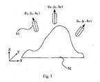
- FIG. 3 is an explanatory diagram for setting the tool axis attitude.
- the tool axis attitude deciding member 21 set a plurality of tool axis attitudes (i1, j1, k1), (i2, j2, k2) to (in, jn, kn).
- the controller 3 defines a direction cosine T(i, j, k) indicating the tool axis attitude.
- the tool attitude in ⁇ , ⁇ is defined as T ⁇ .
- the controller 3 represents all surfaces of the finished workpiece profile by a polyhedron of the plural micro triangle planes.
- Each of the plural micro triangle planes is defined as a triangle vector Vi having its direction coinciding with a normal direction to the micro triangle plane and its length being a vector with an area of the micro triangle plane.
- Step 3 the controller 3 calculates the scalar product T ⁇ x Vi multiplying the tool axis attitude T ⁇ with the triangle vector Vi and adds the calculated value of the scalar product to a scalar product deciding value N(1) ⁇ if the calculated value is +(plus).
- This process is executed every tool axis attitude T ⁇ over the whole of the finished workpiece profile, that is to say every triangle vector Vi. Therefore, the scalar product deciding value N(1) ⁇ is a summed value of the scalar product T ⁇ x Vi every tool axis attitude T ⁇ where the value is plus.
- Step 4 the controller 3 executes the Step 3 at all tool axis attitudes T ⁇ to calculate the scalar product deciding value N(1) ⁇ every tool axis attitude.
- Step 5 the controller 3 aligns the tool axis attitude T ⁇ in descending order of the scalar product deciding value N(1) ⁇ to establish a rank order of the tool axis attitude T ⁇ .
- Step 6 the controller 3 decides as the first tool axis attitude the maximum tool axis attitude T ⁇ where the scalar product deciding value N(1) ⁇ is maximum.
- Step 7 the controller 3 calculates the scalar product T ⁇ x Vi multiplying the tool axis attitude T ⁇ with the triangle vector Vi in relation to the tool axis attitude T ⁇ except for T1.
- the controller 3 adds the calculated value to the scalar product deciding value N(2)N ⁇ if the condition of T ⁇ x Vi > Tl x Vi is satisfied.
- This process is executed every tool axis attitude T ⁇ over the whole of the finished workpiece profile, that is to say every triangle vector Vi. Therefore, the scalar product deciding value N(2) ⁇ is a summed value of the scalar product T ⁇ x Vi every tool axis attitude T ⁇ where the condition of T ⁇ x Vi > T1 x Vi is satisfied.
- Step 8 the controller 3 executes the Step 7 every each of the all tool axis attitude T ⁇ except for T1 to calculate the scalar product deciding value N(2) ⁇ every tool axis attitude.
- Step 9 the controller 3 aligns the tool axis attitude T ⁇ in descending order of the scalar product deciding value N(2) ⁇ to establish the rank order of the tool axis attitude T ⁇ .
- Step 10 the controller 3 decides as the second tool axis attitude the maximum tool axis attitude T ⁇ where the scalar product deciding value N(2) ⁇ is maximum.
- Step 11 the controller 3 continues to decide the tool axis attitude T3, T4 to Tn until there is no scalar product T ⁇ satisfying the condition of T ⁇ x Vi > Tn x Vi where n is a number of the tool axis attitude decided by the controller 3.
- the controller 3 finishes to decide the tool axis attitude.
- Fig. 4 is a diagram showing one example of an interference template 53 and is a side view of the interference template 53.
- the interference template 53 is a profile combining a cone with a needle projecting at a top edge to a normal direction.
- the interference template 53 may be constructed by other profile, for example an approximate profile to an upside down reversed predetermined tool holder or tool based on the predetermined tool holder or tool, or the cone may be a pyramid.
- a tooling is pre-determined.
- L/D is an index showing an extent how high or low stiffness of the tool holder and the tool is.
- the reference value "r" is for example six.
- the interference template 53 is the upside down profile with the combination of the cone including a range of a profile of the tool holder and the needle having a length coinciding an edge position of the tool with an edge of the needle in relation of the decided predetermined tooling.
- the needle runs through a center line of the tool.
- a size of the interference template 53 is decided by obtaining values of the tool holder diameter and the index L/D.
- the value of the tool holder diameter is the maximum value suitable for an actual using tool during the tool holder registered in the tool holder data 42.
- Fig. 5 is a diagram showing the tool 51, the finished workpiece profile 52 and the interference template 53 in a finished workpiece coordinate (Xt, Yt, Zt).
- a direction of the finished workpiece profile 52 is defined by uniqueness theorem in the finished workpiece coordinate (Xt, Yt, Zt).
- the direction of the tool 51 is decided. All of the directions of the tool 51, the finished workpiece profile 52 and the interference template 53 are decided by coinciding the tool axis attitude (i1, j1, k1), that is the direction of the tool 51, with the direction of the interference template 53, that is the direction of the needle.
- Fig. 6 is a diagram showing the tool 51, the finished workpiece profile 52 and the interference template 53 in a tool axis coordinate (Xm, Ym, Zm).
- the finished workpiece profile 52 and the interference template 53 is relatively transformed by coinciding the one selected tool axis attitude (i1, j1, k1) with a plus direction in Z-axis from a state shown in Fig. 5 to a state shown in Fig. 6 , the directions of the tool 51, the direction of the tool 51, the finished workpiece profile 52 and the interference template 53 is decided in the tool axis coordinate (Xm, Ym, Zm).
- the transformation from the finished workpiece coordinate to the tool axis coordinate is a specific process where a Z map method is selected as a profile representing method.
- the Z map method is to divide a X-Y plane to square profiles in a three dimensional space including the representing profile and to define single profile surface value (Z value) in a Z axis every square in order to represent a whole profile of the finished workpiece. There is no need for transforming from the finished workpiece coordinate to the tool axis coordinate where the other profile representing method.
- Fig. 7 is an explanatory diagram explaining process of the interference dangerous zone deciding member 23.
- Fig. 7 shows the process of the interference dangerous zone deciding member 23 to decide an interference dangerous zone 54 by the same thinking method of to a reversing offset method against the finished workpiece profile shown in Fig. 6 .
- the controller 3 moves the interference template 53 in a way that the top edge of the needle of the interference template 53 traces on a line of the surface of the finished workpiece 52, thereby to register trajectory datum of the movement of the interference template 53 in a workpiece memory zone of the RAM.
- the controller 3 determines as the interference dangerous zone the zone included by the plural cones and registered in the workpiece memory zone to register the decided interference dangerous zone as an interference dangerous zone data 45 in the zone data base 35 of the memory 5.
- an enveloping surface is represented by a wide line for your convenience to show the interference dangerous zone 54 inside the enveloping surface to a minus direction of a Zm axis from a reference of the wide line.
- Fig. 8 is a diagram showing one example of a virtual tool holder 55.
- the virtual tool holder 55 shown in Fig. 8 is the tool holder registered in the tooling data base 37 as the virtual tool holder data 47 for the initial value.
- Fig. 9 is an explanatory diagram explaining a portion, which should be eliminated because of the interference, in the virtual tool holder 55.
- a workpiece profile 57 shown in Fig. 9 includes in adding to a part of the finished workpiece profile a machined portion shown by an oblique line.
- the machining simulation member 25 decides, every decided tool axis attitude in Step 1 to Step 11, a machining zone in a way of avoiding the possible interference dangerous zone that is the zone machined by the one identified tool axis attitude.
- the machining simulation member 25 sets the virtual tool holder 55 shown in Fig. 8 to the tool 51 and performs the machining simulation for the decided machining zone.
- the virtual tool holder 55 shown in Fig. 8 is set to be larger than the tool holder related to a random tool holder 42 registered in the device data base 31.
- the machining simulation member 25 eliminates the interference portion every time where the virtual tool holder 55 interferes with the workpiece profile 57.
- the machining simulation member 25 stores in the tooling data base 37 of the memory 5 the remaining portion, which is not eliminated, as the virtual tool holder data 47 relating to a non-interference virtual tool holder 55.
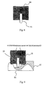
- Fig. 10 is a diagram showing a selectable tooling.
- Fig. 11 is a diagram showing a decided tooling.
- the non-interference tooling deciding member 27 selects the tooling included in the range of the profile of the virtual tool holder 55 shown in Fig. 10 and having the highest stiffness from a group of a tool holder 56a, a tool holder 56b and a tool holder 56c.
- Fig. 10 shows only the selection of the tool holder, however the fittest tool 51 should be selected in referring to the tool datum registered in the device data base 31.
- the non-interference tooling deciding member 27 decides the tooling having the highest stiffness by selecting a combination having the highest bending stiffness when the tool is installed in the tool holder and registers the decided tooling in the tooling data base 37 of the memory 5 as the non-interference tooling data 48. In one example, it is selected the combination of the tool 51 and the tool holder 56c having the highest bending stiffness as shown in Fig. 11 .
- the profile of the virtual tool holder 55 shown in Fig. 10 can not interfere with the workpiece profile 57 because the portions interfering with the workpiece profile 57 are eliminated by the machining simulation member 25.
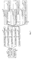
- Fig. 12 is a diagram showing a flowchart for the embodiment of the machining parameter optimizing apparatus 1.
- the embodiment is the simulation for machining a die and so on in order of three-axis whole rough machining, three-axis local rough machining and five-axis local rough machining.
- the controller 3 of the machining parameter optimizing apparatus 1 executes the simulation of a three-axis whole rough machining at first in Step 101.
- the controller 3 decides the tool 51 as a large diameter possible to machine the whole finished workpiece profile 52 without any interference and decides that the tool axis attitude is the Z axis direction, thereby executing the simulation of the whole rough machining in Step 101.
- the controller 3 decides the machining zone and generates the virtual tool holder 55.
- the controller 3 executes the operation by the machining simulation member 25 in Step 101.
- Step 102 the controller 3 executes to generate the non-interference tooling.
- the controller 3 generates the tooling with the tool 51 having the large diameter and without any interference in Step 102.
- the controller 3 executes the process by the non-interference tooling deciding member 27 in Step 102.
- the tooling generated in Step 102 is for the three-axis whole rough machining.
- Step 103 the controller 3 executes to extract the remaining machining zone.
- Step 103 the controller 3 extracts a non-machining zone remained in Step 101.
- the controller 3 executes the operation by the remaining area extracting member 29 in Step 103.
- Step 104 the controller 3 executes to generate the interference dangerous zone of the three-axis attitude.
- the controller 3 generates the interference dangerous zone by the interference template 53 in which the tool attitude is the Z axis direction in Step 104.
- the controller 3 executes the operation by the interference dangerous zone determining member 23 in Step 104.
- Step 105 the controller 3 executes the simulation of the three-axis local machining.
- the controller 3 decides that the tool 51 is one having a small diameter for the remaining machining zone extracted in Step 103 and also decides that the tool axis attitude is the Z axis direction, thereby executing the simulation of the local rough machining. Then the controller 3 executes to decide the machining zone and generates the virtual tool holder 55. The controller 3 executes the process by the machining simulation member 25 in Step 105.
- Step 106 the controller 3 executes to generate the non-interference tooling.
- the controller 3 generates the tooling in which the tool has the small diameter and the interference is not occurred on a basis of the virtual tool holder 55 generated in Step 105.
- the controller 3 executes the process by the non-interference tooling deciding member 27 in Step 106.
- the tooling generated in Step 102 is for the three-axis local rough machining.
- Step 7 the controller 3 executes to extract the remaining machining zone.
- the controller 3 extracts in Step 107 the non-machining zone remaining after Step 105.
- the controller 3 executes the process by the remaining machining zone extracting member 29 in Step 107.
- Step 108 the controller 3 executes to set the tool axis attitude.
- Step 108 the controller 3 sets for Step 109 to Step 112 another tool axis attitude different from the previously set tool axis attitude.
- the controller 3 executes the process by the tool axis attitude determining member 21 in Step 108.
- Step 109 the controller 3 executes to generate the interference dangerous zone for five-axis attitudes.
- the controller 3 sets in Step 109 the interference template 53 according to the tool axis attitude set in Step 108 and generates the interference dangerous zone.
- the controller 3 executes the process by the interference dangerous zone deciding member 23 in Step 109.
- Step 110 the controller 3 executes the simulation of the five-axis local rough machining.
- the controller 3 decides that the tool 51 is one having a small diameter for the remaining area extracted in Step 107, thereby executing the local rough machining simulation according to the tool axis attitude set in Step 108. Then the controller 3 executes to decide the machining zone and generates the virtual tool holder 55. The controller 3 executes the process by the machining simulation member 25 in Step 110.
- Step 111 the controller 3 executes to extract the remaining machining zone.
- the controller 3 extracts in Step 111 the non-machining zone remaining after Step 110.
- the controller 3 executes the process by the remaining machining zone extracting member 29 in Step 111.
- Step 112 the controller 3 executes to judge the machining remaining, and repeats from the Step 108 to Step 111 where there exists the remaining machining zone or finishes the process where there is no remaining machining zone.
- Step 113 the controller 3 executes to generate the non-interference tooling.
- the controller 3 generates in Step 113 the tooling, in which the diameter of tool 51 is small and in which interference is not occurred, based on the virtual tool holder generated finally in Step 110.
- the controller 3 executes the process by the non-interference tooling deciding member 27 in Step 113.
- the tooling generated in Step 113 is applied over the process for the five-axis local rough machining.
- the one embodiment of the present invention it is possible to increase a machining efficiency by eliminating a tool changer in the process of the five-axis local rough machining because the one embodiment of the present invention decides one optimized tooling based on the virtual tool holder 55 generated finally in Step 110 after the controller 3 repeats to decide the tool axis attitude, to decide the interference dangerous zone, to generate the virtual tool holder and to extract the remaining machining area from Step 108 to Step 112 until there is no remaining machining zone.
- the controller 3 may execute to decide the tooling every tool axis attitude even in the same process of the five-axis local rough machining. In this case, the controller 3 executes to decide the tooling after Step 111 on the basis of the tool axis attitude decided in the Step 108.
- the one embodiment can machine the workpiece by the optimized tooling for each of the tool axis attitude by the way of deciding the tooling every tool axis attitude.
- the machining parameter optimizing apparatus 1 can decide the tooling having the high stiffness as well as decide the tool axis attitude and the machining zone in each machining process of the three-axis whole rough machining, the three-axis local rough machining and the five-axis local rough machining..
- a tool axis attitude deciding member 21 decides one or plural tool axis attitude.
- An interference dangerous zone deciding member 23 decides as an interference dangerous zone a zone possible to interfere between a tool or a tool holder and a workpiece during machining by the decided tool axis attitude.
- a machining simulation member 25 executes a machining simulation based on the interference dangerous zone by the decided tool axis attitude and generates the virtual tool holder in which there is no any interference, and also decides a machining zone in a way of avoiding the interference dangerous zone.
- a non-interference tooling deciding member 27 deciding the tooling included in a range of a profile of the virtual tool holder, the tooling is a combination of the tool and the tool holder having the highest stiffness.
Landscapes
- Physics & Mathematics (AREA)
- Engineering & Computer Science (AREA)
- Geometry (AREA)
- Human Computer Interaction (AREA)
- Manufacturing & Machinery (AREA)
- General Physics & Mathematics (AREA)
- Automation & Control Theory (AREA)
- Numerical Control (AREA)
Applications Claiming Priority (1)
| Application Number | Priority Date | Filing Date | Title |
|---|---|---|---|
| JP2008202646A JP5142880B2 (ja) | 2008-08-06 | 2008-08-06 | 加工パラメータ最適化装置、加工パラメータ最適化方法およびプログラム |
Publications (3)
| Publication Number | Publication Date |
|---|---|
| EP2154589A2 true EP2154589A2 (de) | 2010-02-17 |
| EP2154589A3 EP2154589A3 (de) | 2011-10-05 |
| EP2154589B1 EP2154589B1 (de) | 2014-03-19 |
Family
ID=41319705
Family Applications (1)
| Application Number | Title | Priority Date | Filing Date |
|---|---|---|---|
| EP09166624.8A Not-in-force EP2154589B1 (de) | 2008-08-06 | 2009-07-28 | Vorrichtung zur Optimierung der Bearbeitungsparameter, Verfahren zur Optimierung der Bearbeitungsparameter und Programm dafür |
Country Status (3)
| Country | Link |
|---|---|
| US (1) | US8200360B2 (de) |
| EP (1) | EP2154589B1 (de) |
| JP (1) | JP5142880B2 (de) |
Families Citing this family (9)
| Publication number | Priority date | Publication date | Assignee | Title |
|---|---|---|---|---|
| JP5139230B2 (ja) * | 2008-10-06 | 2013-02-06 | オークマ株式会社 | 数値制御装置における衝突防止装置 |
| JP5334701B2 (ja) | 2009-06-22 | 2013-11-06 | 株式会社ジェイテクト | 最適工程決定装置および最適工程決定方法 |
| JP2012218111A (ja) * | 2011-04-08 | 2012-11-12 | Fanuc Ltd | 工具ホルダおよび工具ホルダへの工具取付け長さを決定する機能を備えた数値制御装置 |
| US8788083B2 (en) | 2011-07-22 | 2014-07-22 | Pratt & Whitney Canada Corp. | Compensation for process variables in a numerically-controlled machining operation |
| JP5901777B2 (ja) * | 2012-09-07 | 2016-04-13 | 株式会社牧野フライス製作所 | 放電加工方法および電極ガイド位置設定装置 |
| JP5969882B2 (ja) * | 2012-10-03 | 2016-08-17 | 株式会社豊田中央研究所 | 加工データ一貫生成装置、加工データ一貫生成プログラム及び加工データ一貫生成方法 |
| SE545056C2 (en) * | 2016-02-19 | 2023-03-14 | Tomologic Ab | Method and machine system for controlling an industrial operation |
| CN111360586A (zh) * | 2020-03-08 | 2020-07-03 | 华中科技大学 | 一种基于标准球的激光出光方向标定方法 |
| JP7766721B2 (ja) * | 2024-01-19 | 2025-11-10 | アルム株式会社 | 工具選択装置、制御方法及び制御プログラム |
Citations (3)
| Publication number | Priority date | Publication date | Assignee | Title |
|---|---|---|---|---|
| JPH09179620A (ja) | 1995-12-26 | 1997-07-11 | Toyota Central Res & Dev Lab Inc | 被干渉体の形態決定方法およびその装置とワーク支持形態の自動決定方法とツーリング形態の自動決定方法 |
| JPH11235646A (ja) | 1998-02-19 | 1999-08-31 | Toyota Central Res & Dev Lab Inc | 加工工程の決定方法 |
| JP2007172300A (ja) | 2005-12-22 | 2007-07-05 | Mazda Motor Corp | 工具の加工姿勢設定方法 |
Family Cites Families (22)
| Publication number | Priority date | Publication date | Assignee | Title |
|---|---|---|---|---|
| JPS58163001A (ja) * | 1982-03-23 | 1983-09-27 | Toyoda Mach Works Ltd | 干渉チエツク機能を備えた数値制御装置 |
| JPS59216208A (ja) * | 1983-05-23 | 1984-12-06 | Mitsubishi Electric Corp | 数値制御装置 |
| US5122966A (en) * | 1989-09-18 | 1992-06-16 | Northern Research & Engineering | Computer generated tool path interference check method |
| JPH0577135A (ja) * | 1991-09-18 | 1993-03-30 | Tsugami Corp | Nc装置における工具軌跡シユミレーシヨン装置 |
| JPH05216527A (ja) * | 1992-02-03 | 1993-08-27 | Fanuc Ltd | グラフィック干渉チェック装置 |
| JPH06114679A (ja) * | 1992-10-06 | 1994-04-26 | Fanuc Ltd | 数値制御装置の加工プログラムチェック方法 |
| JP2845710B2 (ja) * | 1993-03-03 | 1999-01-13 | 株式会社牧野フライス製作所 | 機械加工方法 |
| EP0913229B1 (de) * | 1997-03-15 | 2005-01-19 | Makino Milling Machine Co. Ltd. | Prozessor für maschinelle bearbeitung |
| JP2000084794A (ja) * | 1998-09-14 | 2000-03-28 | Makino Milling Mach Co Ltd | 加工処理装置 |
| JP3517403B2 (ja) * | 2000-06-23 | 2004-04-12 | ヤマザキマザック株式会社 | 複合加工工作機械 |
| KR100563760B1 (ko) * | 2000-07-31 | 2006-03-24 | 가부시키가이샤 도요다 쥬오 겐큐쇼 | 통합 cam 시스템, nc 데이터 생성 방법, 가공 설계 시스템, 가공 데이터 생성 장치 및 기록 매체 |
| JP2005081445A (ja) * | 2003-09-04 | 2005-03-31 | Fanuc Ltd | ロボットの干渉領域確認装置 |
| JP2006004128A (ja) * | 2004-06-17 | 2006-01-05 | Mori Seiki Co Ltd | 干渉確認装置 |
| JP4362095B2 (ja) * | 2004-08-20 | 2009-11-11 | オークマ株式会社 | 数値制御装置 |
| JP4505295B2 (ja) * | 2004-09-16 | 2010-07-21 | ヤマザキマザック株式会社 | Nc加工シミュレーション方法及びnc加工シミュレーション装置 |
| JP2006244067A (ja) * | 2005-03-02 | 2006-09-14 | Saitama Univ | 工作機械の干渉判定方法 |
| EP2048558B1 (de) * | 2006-08-01 | 2012-09-26 | Mitsubishi Electric Corporation | Programmierungsvorrichtung und programmierungsverfahren |
| JP2008097193A (ja) * | 2006-10-10 | 2008-04-24 | Mori Seiki Co Ltd | 工作機械の制御装置 |
| JP4577303B2 (ja) * | 2006-12-08 | 2010-11-10 | 株式会社豊田中央研究所 | 工具軸姿勢決定装置、工具軸姿勢決定方法、プログラム |
| JP5384178B2 (ja) * | 2008-04-21 | 2014-01-08 | 株式会社森精機製作所 | 加工シミュレーション方法及び加工シミュレーション装置 |
| JP4920785B2 (ja) * | 2008-04-22 | 2012-04-18 | 三菱電機株式会社 | 数値制御方法及びその装置 |
| JP5139230B2 (ja) * | 2008-10-06 | 2013-02-06 | オークマ株式会社 | 数値制御装置における衝突防止装置 |
-
2008
- 2008-08-06 JP JP2008202646A patent/JP5142880B2/ja not_active Expired - Fee Related
-
2009
- 2009-07-28 EP EP09166624.8A patent/EP2154589B1/de not_active Not-in-force
- 2009-07-29 US US12/511,716 patent/US8200360B2/en not_active Expired - Fee Related
Patent Citations (3)
| Publication number | Priority date | Publication date | Assignee | Title |
|---|---|---|---|---|
| JPH09179620A (ja) | 1995-12-26 | 1997-07-11 | Toyota Central Res & Dev Lab Inc | 被干渉体の形態決定方法およびその装置とワーク支持形態の自動決定方法とツーリング形態の自動決定方法 |
| JPH11235646A (ja) | 1998-02-19 | 1999-08-31 | Toyota Central Res & Dev Lab Inc | 加工工程の決定方法 |
| JP2007172300A (ja) | 2005-12-22 | 2007-07-05 | Mazda Motor Corp | 工具の加工姿勢設定方法 |
Also Published As
| Publication number | Publication date |
|---|---|
| US8200360B2 (en) | 2012-06-12 |
| EP2154589B1 (de) | 2014-03-19 |
| US20100036519A1 (en) | 2010-02-11 |
| JP5142880B2 (ja) | 2013-02-13 |
| EP2154589A3 (de) | 2011-10-05 |
| JP2010036309A (ja) | 2010-02-18 |
Similar Documents
| Publication | Publication Date | Title |
|---|---|---|
| EP2154589B1 (de) | Vorrichtung zur Optimierung der Bearbeitungsparameter, Verfahren zur Optimierung der Bearbeitungsparameter und Programm dafür | |
| EP1498792B1 (de) | Vorrichtung zur Off- line Simulation von robotischen Arbeitsgängen | |
| Bedi et al. | Advanced interpolation techniques for NC machines | |
| US7894930B2 (en) | Method and device for composite machining based on tool-path pattern types with tool axis orientation rules | |
| Lin | Real-time surface interpolator for 3-D parametric surface machining on 3-axis machine tools | |
| EP3964904B1 (de) | Informationsverarbeitungsvorrichtung, informationsverarbeitungsverfahren und informationsverarbeitungsprogramm | |
| JP5458115B2 (ja) | 加工経路生成方法及びその装置 | |
| US8432120B2 (en) | Tool path display apparatus with deceleration factor identification means for machine tool | |
| Xu et al. | Five-axis tool path and feed rate optimization based on the cutting force–area quotient potential field | |
| EP3206100B1 (de) | Planung von computer numerischen gesteuerten (cnc) bearbeitungsvorgängen mit hilfe eines digitalen computers | |
| Ko et al. | Off-line feed rate scheduling using virtual CNC based on an evaluation of cutting performance | |
| US6842664B2 (en) | Control apparatus for cutting machine, cutting machine and cutting method | |
| Bailey et al. | Generic simulation approach for multi-axis machining, part 1: modeling methodology | |
| US7239938B2 (en) | Interference checking for a numerical control device | |
| Ju et al. | A solid-analytical-based method for extracting cutter-workpiece engagement in sculptured surface milling | |
| Economou et al. | Maximally robust input preconditioning for residual vibration suppression using low-pass fir digital filters | |
| JP3066646B2 (ja) | 動作シミュレーションシステム | |
| JP2002529843A (ja) | 機械部分を生成するための画像cncプログラム | |
| JP2002529843A5 (de) | ||
| JP2014073546A (ja) | 加工データ一貫生成装置、加工データ一貫生成プログラム及び加工データ一貫生成方法 | |
| Zhang et al. | Design and development of an in situ machining simulation system using augmented reality technology | |
| Ozturk et al. | Analytical methods for increased productivity in five-axis ball-end milling | |
| JP6219866B2 (ja) | 表示機能付き数値制御装置および表示プログラム | |
| JP6896144B2 (ja) | 工具経路生成方法 | |
| JPH07136900A (ja) | Nc加工方法 |
Legal Events
| Date | Code | Title | Description |
|---|---|---|---|
| PUAI | Public reference made under article 153(3) epc to a published international application that has entered the european phase |
Free format text: ORIGINAL CODE: 0009012 |
|
| AK | Designated contracting states |
Kind code of ref document: A2 Designated state(s): AT BE BG CH CY CZ DE DK EE ES FI FR GB GR HR HU IE IS IT LI LT LU LV MC MK MT NL NO PL PT RO SE SI SK SM TR |
|
| AX | Request for extension of the european patent |
Extension state: AL BA RS |
|
| PUAL | Search report despatched |
Free format text: ORIGINAL CODE: 0009013 |
|
| AK | Designated contracting states |
Kind code of ref document: A3 Designated state(s): AT BE BG CH CY CZ DE DK EE ES FI FR GB GR HR HU IE IS IT LI LT LU LV MC MK MT NL NO PL PT RO SE SI SK SM TR |
|
| AX | Request for extension of the european patent |
Extension state: AL BA RS |
|
| RIC1 | Information provided on ipc code assigned before grant |
Ipc: B23Q 15/00 20060101ALI20110829BHEP Ipc: G05B 19/4093 20060101ALI20110829BHEP Ipc: G05B 17/02 20060101AFI20110829BHEP Ipc: G05B 19/18 20060101ALI20110829BHEP Ipc: G05B 23/02 20060101ALI20110829BHEP |
|
| 17P | Request for examination filed |
Effective date: 20120405 |
|
| 17Q | First examination report despatched |
Effective date: 20121114 |
|
| GRAP | Despatch of communication of intention to grant a patent |
Free format text: ORIGINAL CODE: EPIDOSNIGR1 |
|
| INTG | Intention to grant announced |
Effective date: 20131128 |
|
| GRAS | Grant fee paid |
Free format text: ORIGINAL CODE: EPIDOSNIGR3 |
|
| GRAA | (expected) grant |
Free format text: ORIGINAL CODE: 0009210 |
|
| AK | Designated contracting states |
Kind code of ref document: B1 Designated state(s): AT BE BG CH CY CZ DE DK EE ES FI FR GB GR HR HU IE IS IT LI LT LU LV MC MK MT NL NO PL PT RO SE SI SK SM TR |
|
| REG | Reference to a national code |
Ref country code: GB Ref legal event code: FG4D |
|
| REG | Reference to a national code |
Ref country code: CH Ref legal event code: EP |
|
| REG | Reference to a national code |
Ref country code: IE Ref legal event code: FG4D |
|
| REG | Reference to a national code |
Ref country code: AT Ref legal event code: REF Ref document number: 658050 Country of ref document: AT Kind code of ref document: T Effective date: 20140415 |
|
| REG | Reference to a national code |
Ref country code: DE Ref legal event code: R096 Ref document number: 602009022566 Country of ref document: DE Effective date: 20140430 |
|
| PG25 | Lapsed in a contracting state [announced via postgrant information from national office to epo] |
Ref country code: LT Free format text: LAPSE BECAUSE OF FAILURE TO SUBMIT A TRANSLATION OF THE DESCRIPTION OR TO PAY THE FEE WITHIN THE PRESCRIBED TIME-LIMIT Effective date: 20140319 Ref country code: NO Free format text: LAPSE BECAUSE OF FAILURE TO SUBMIT A TRANSLATION OF THE DESCRIPTION OR TO PAY THE FEE WITHIN THE PRESCRIBED TIME-LIMIT Effective date: 20140619 |
|
| REG | Reference to a national code |
Ref country code: NL Ref legal event code: VDEP Effective date: 20140319 |
|
| REG | Reference to a national code |
Ref country code: AT Ref legal event code: MK05 Ref document number: 658050 Country of ref document: AT Kind code of ref document: T Effective date: 20140319 |
|
| REG | Reference to a national code |
Ref country code: LT Ref legal event code: MG4D |
|
| PG25 | Lapsed in a contracting state [announced via postgrant information from national office to epo] |
Ref country code: CY Free format text: LAPSE BECAUSE OF FAILURE TO SUBMIT A TRANSLATION OF THE DESCRIPTION OR TO PAY THE FEE WITHIN THE PRESCRIBED TIME-LIMIT Effective date: 20140319 Ref country code: FI Free format text: LAPSE BECAUSE OF FAILURE TO SUBMIT A TRANSLATION OF THE DESCRIPTION OR TO PAY THE FEE WITHIN THE PRESCRIBED TIME-LIMIT Effective date: 20140319 Ref country code: SE Free format text: LAPSE BECAUSE OF FAILURE TO SUBMIT A TRANSLATION OF THE DESCRIPTION OR TO PAY THE FEE WITHIN THE PRESCRIBED TIME-LIMIT Effective date: 20140319 |
|
| PG25 | Lapsed in a contracting state [announced via postgrant information from national office to epo] |
Ref country code: HR Free format text: LAPSE BECAUSE OF FAILURE TO SUBMIT A TRANSLATION OF THE DESCRIPTION OR TO PAY THE FEE WITHIN THE PRESCRIBED TIME-LIMIT Effective date: 20140319 Ref country code: LV Free format text: LAPSE BECAUSE OF FAILURE TO SUBMIT A TRANSLATION OF THE DESCRIPTION OR TO PAY THE FEE WITHIN THE PRESCRIBED TIME-LIMIT Effective date: 20140319 |
|
| PG25 | Lapsed in a contracting state [announced via postgrant information from national office to epo] |
Ref country code: CZ Free format text: LAPSE BECAUSE OF FAILURE TO SUBMIT A TRANSLATION OF THE DESCRIPTION OR TO PAY THE FEE WITHIN THE PRESCRIBED TIME-LIMIT Effective date: 20140319 Ref country code: NL Free format text: LAPSE BECAUSE OF FAILURE TO SUBMIT A TRANSLATION OF THE DESCRIPTION OR TO PAY THE FEE WITHIN THE PRESCRIBED TIME-LIMIT Effective date: 20140319 Ref country code: EE Free format text: LAPSE BECAUSE OF FAILURE TO SUBMIT A TRANSLATION OF THE DESCRIPTION OR TO PAY THE FEE WITHIN THE PRESCRIBED TIME-LIMIT Effective date: 20140319 Ref country code: BG Free format text: LAPSE BECAUSE OF FAILURE TO SUBMIT A TRANSLATION OF THE DESCRIPTION OR TO PAY THE FEE WITHIN THE PRESCRIBED TIME-LIMIT Effective date: 20140619 Ref country code: BE Free format text: LAPSE BECAUSE OF FAILURE TO SUBMIT A TRANSLATION OF THE DESCRIPTION OR TO PAY THE FEE WITHIN THE PRESCRIBED TIME-LIMIT Effective date: 20140319 Ref country code: RO Free format text: LAPSE BECAUSE OF FAILURE TO SUBMIT A TRANSLATION OF THE DESCRIPTION OR TO PAY THE FEE WITHIN THE PRESCRIBED TIME-LIMIT Effective date: 20140319 Ref country code: IS Free format text: LAPSE BECAUSE OF FAILURE TO SUBMIT A TRANSLATION OF THE DESCRIPTION OR TO PAY THE FEE WITHIN THE PRESCRIBED TIME-LIMIT Effective date: 20140719 |
|
| PG25 | Lapsed in a contracting state [announced via postgrant information from national office to epo] |
Ref country code: AT Free format text: LAPSE BECAUSE OF FAILURE TO SUBMIT A TRANSLATION OF THE DESCRIPTION OR TO PAY THE FEE WITHIN THE PRESCRIBED TIME-LIMIT Effective date: 20140319 Ref country code: ES Free format text: LAPSE BECAUSE OF FAILURE TO SUBMIT A TRANSLATION OF THE DESCRIPTION OR TO PAY THE FEE WITHIN THE PRESCRIBED TIME-LIMIT Effective date: 20140319 Ref country code: PL Free format text: LAPSE BECAUSE OF FAILURE TO SUBMIT A TRANSLATION OF THE DESCRIPTION OR TO PAY THE FEE WITHIN THE PRESCRIBED TIME-LIMIT Effective date: 20140319 Ref country code: SK Free format text: LAPSE BECAUSE OF FAILURE TO SUBMIT A TRANSLATION OF THE DESCRIPTION OR TO PAY THE FEE WITHIN THE PRESCRIBED TIME-LIMIT Effective date: 20140319 |
|
| REG | Reference to a national code |
Ref country code: DE Ref legal event code: R097 Ref document number: 602009022566 Country of ref document: DE |
|
| PG25 | Lapsed in a contracting state [announced via postgrant information from national office to epo] |
Ref country code: PT Free format text: LAPSE BECAUSE OF FAILURE TO SUBMIT A TRANSLATION OF THE DESCRIPTION OR TO PAY THE FEE WITHIN THE PRESCRIBED TIME-LIMIT Effective date: 20140721 |
|
| PLBE | No opposition filed within time limit |
Free format text: ORIGINAL CODE: 0009261 |
|
| STAA | Information on the status of an ep patent application or granted ep patent |
Free format text: STATUS: NO OPPOSITION FILED WITHIN TIME LIMIT |
|
| PG25 | Lapsed in a contracting state [announced via postgrant information from national office to epo] |
Ref country code: DK Free format text: LAPSE BECAUSE OF FAILURE TO SUBMIT A TRANSLATION OF THE DESCRIPTION OR TO PAY THE FEE WITHIN THE PRESCRIBED TIME-LIMIT Effective date: 20140319 |
|
| 26N | No opposition filed |
Effective date: 20141222 |
|
| PG25 | Lapsed in a contracting state [announced via postgrant information from national office to epo] |
Ref country code: LU Free format text: LAPSE BECAUSE OF FAILURE TO SUBMIT A TRANSLATION OF THE DESCRIPTION OR TO PAY THE FEE WITHIN THE PRESCRIBED TIME-LIMIT Effective date: 20140728 |
|
| REG | Reference to a national code |
Ref country code: CH Ref legal event code: PL |
|
| GBPC | Gb: european patent ceased through non-payment of renewal fee |
Effective date: 20140728 |
|
| PG25 | Lapsed in a contracting state [announced via postgrant information from national office to epo] |
Ref country code: IT Free format text: LAPSE BECAUSE OF FAILURE TO SUBMIT A TRANSLATION OF THE DESCRIPTION OR TO PAY THE FEE WITHIN THE PRESCRIBED TIME-LIMIT Effective date: 20140319 |
|
| REG | Reference to a national code |
Ref country code: DE Ref legal event code: R097 Ref document number: 602009022566 Country of ref document: DE Effective date: 20141222 |
|
| REG | Reference to a national code |
Ref country code: IE Ref legal event code: MM4A |
|
| REG | Reference to a national code |
Ref country code: FR Ref legal event code: ST Effective date: 20150331 |
|
| PG25 | Lapsed in a contracting state [announced via postgrant information from national office to epo] |
Ref country code: CH Free format text: LAPSE BECAUSE OF NON-PAYMENT OF DUE FEES Effective date: 20140731 Ref country code: LI Free format text: LAPSE BECAUSE OF NON-PAYMENT OF DUE FEES Effective date: 20140731 |
|
| PG25 | Lapsed in a contracting state [announced via postgrant information from national office to epo] |
Ref country code: GB Free format text: LAPSE BECAUSE OF NON-PAYMENT OF DUE FEES Effective date: 20140728 Ref country code: FR Free format text: LAPSE BECAUSE OF NON-PAYMENT OF DUE FEES Effective date: 20140731 |
|
| PG25 | Lapsed in a contracting state [announced via postgrant information from national office to epo] |
Ref country code: SI Free format text: LAPSE BECAUSE OF FAILURE TO SUBMIT A TRANSLATION OF THE DESCRIPTION OR TO PAY THE FEE WITHIN THE PRESCRIBED TIME-LIMIT Effective date: 20140319 |
|
| PG25 | Lapsed in a contracting state [announced via postgrant information from national office to epo] |
Ref country code: IE Free format text: LAPSE BECAUSE OF NON-PAYMENT OF DUE FEES Effective date: 20140728 |
|
| PG25 | Lapsed in a contracting state [announced via postgrant information from national office to epo] |
Ref country code: SM Free format text: LAPSE BECAUSE OF FAILURE TO SUBMIT A TRANSLATION OF THE DESCRIPTION OR TO PAY THE FEE WITHIN THE PRESCRIBED TIME-LIMIT Effective date: 20140319 Ref country code: MC Free format text: LAPSE BECAUSE OF FAILURE TO SUBMIT A TRANSLATION OF THE DESCRIPTION OR TO PAY THE FEE WITHIN THE PRESCRIBED TIME-LIMIT Effective date: 20140319 |
|
| PG25 | Lapsed in a contracting state [announced via postgrant information from national office to epo] |
Ref country code: MT Free format text: LAPSE BECAUSE OF FAILURE TO SUBMIT A TRANSLATION OF THE DESCRIPTION OR TO PAY THE FEE WITHIN THE PRESCRIBED TIME-LIMIT Effective date: 20140319 Ref country code: GR Free format text: LAPSE BECAUSE OF FAILURE TO SUBMIT A TRANSLATION OF THE DESCRIPTION OR TO PAY THE FEE WITHIN THE PRESCRIBED TIME-LIMIT Effective date: 20140620 |
|
| PG25 | Lapsed in a contracting state [announced via postgrant information from national office to epo] |
Ref country code: HU Free format text: LAPSE BECAUSE OF FAILURE TO SUBMIT A TRANSLATION OF THE DESCRIPTION OR TO PAY THE FEE WITHIN THE PRESCRIBED TIME-LIMIT; INVALID AB INITIO Effective date: 20090728 Ref country code: TR Free format text: LAPSE BECAUSE OF FAILURE TO SUBMIT A TRANSLATION OF THE DESCRIPTION OR TO PAY THE FEE WITHIN THE PRESCRIBED TIME-LIMIT Effective date: 20140319 |
|
| PG25 | Lapsed in a contracting state [announced via postgrant information from national office to epo] |
Ref country code: MK Free format text: LAPSE BECAUSE OF FAILURE TO SUBMIT A TRANSLATION OF THE DESCRIPTION OR TO PAY THE FEE WITHIN THE PRESCRIBED TIME-LIMIT Effective date: 20140319 |
|
| PGFP | Annual fee paid to national office [announced via postgrant information from national office to epo] |
Ref country code: DE Payment date: 20200714 Year of fee payment: 12 |
|
| REG | Reference to a national code |
Ref country code: DE Ref legal event code: R119 Ref document number: 602009022566 Country of ref document: DE |
|
| PG25 | Lapsed in a contracting state [announced via postgrant information from national office to epo] |
Ref country code: DE Free format text: LAPSE BECAUSE OF NON-PAYMENT OF DUE FEES Effective date: 20220201 |