EP1498792B1 - Vorrichtung zur Off- line Simulation von robotischen Arbeitsgängen - Google Patents
Vorrichtung zur Off- line Simulation von robotischen Arbeitsgängen Download PDFInfo
- Publication number
- EP1498792B1 EP1498792B1 EP04254016A EP04254016A EP1498792B1 EP 1498792 B1 EP1498792 B1 EP 1498792B1 EP 04254016 A EP04254016 A EP 04254016A EP 04254016 A EP04254016 A EP 04254016A EP 1498792 B1 EP1498792 B1 EP 1498792B1
- Authority
- EP
- European Patent Office
- Prior art keywords
- robot
- determined
- workpiece
- point
- points
- Prior art date
- Legal status (The legal status is an assumption and is not a legal conclusion. Google has not performed a legal analysis and makes no representation as to the accuracy of the status listed.)
- Expired - Lifetime
Links
Images




Classifications
-
- B—PERFORMING OPERATIONS; TRANSPORTING
- B25—HAND TOOLS; PORTABLE POWER-DRIVEN TOOLS; MANIPULATORS
- B25J—MANIPULATORS; CHAMBERS PROVIDED WITH MANIPULATION DEVICES
- B25J9/00—Program-controlled manipulators
- B25J9/16—Program controls
- B25J9/1656—Program controls characterised by programming, planning systems for manipulators
- B25J9/1671—Program controls characterised by programming, planning systems for manipulators characterised by simulation, either to verify existing program or to create and verify new program, CAD/CAM oriented, graphic oriented programming systems
-
- B—PERFORMING OPERATIONS; TRANSPORTING
- B25—HAND TOOLS; PORTABLE POWER-DRIVEN TOOLS; MANIPULATORS
- B25J—MANIPULATORS; CHAMBERS PROVIDED WITH MANIPULATION DEVICES
- B25J9/00—Program-controlled manipulators
- B25J9/16—Program controls
- B25J9/1656—Program controls characterised by programming, planning systems for manipulators
- B25J9/1664—Program controls characterised by programming, planning systems for manipulators characterised by motion, path, trajectory planning
-
- G—PHYSICS
- G05—CONTROLLING; REGULATING
- G05B—CONTROL OR REGULATING SYSTEMS IN GENERAL; FUNCTIONAL ELEMENTS OF SUCH SYSTEMS; MONITORING OR TESTING ARRANGEMENTS FOR SUCH SYSTEMS OR ELEMENTS
- G05B2219/00—Program-control systems
- G05B2219/30—Nc systems
- G05B2219/40—Robotics, robotics mapping to robotics vision
- G05B2219/40317—For collision avoidance and detection
-
- G—PHYSICS
- G05—CONTROLLING; REGULATING
- G05B—CONTROL OR REGULATING SYSTEMS IN GENERAL; FUNCTIONAL ELEMENTS OF SUCH SYSTEMS; MONITORING OR TESTING ARRANGEMENTS FOR SUCH SYSTEMS OR ELEMENTS
- G05B2219/00—Program-control systems
- G05B2219/30—Nc systems
- G05B2219/40—Robotics, robotics mapping to robotics vision
- G05B2219/40465—Criteria is lowest cost function, minimum work path
-
- G—PHYSICS
- G05—CONTROLLING; REGULATING
- G05B—CONTROL OR REGULATING SYSTEMS IN GENERAL; FUNCTIONAL ELEMENTS OF SUCH SYSTEMS; MONITORING OR TESTING ARRANGEMENTS FOR SUCH SYSTEMS OR ELEMENTS
- G05B2219/00—Program-control systems
- G05B2219/30—Nc systems
- G05B2219/40—Robotics, robotics mapping to robotics vision
- G05B2219/40515—Integration of simulation and planning
-
- G—PHYSICS
- G05—CONTROLLING; REGULATING
- G05B—CONTROL OR REGULATING SYSTEMS IN GENERAL; FUNCTIONAL ELEMENTS OF SUCH SYSTEMS; MONITORING OR TESTING ARRANGEMENTS FOR SUCH SYSTEMS OR ELEMENTS
- G05B2219/00—Program-control systems
- G05B2219/30—Nc systems
- G05B2219/40—Robotics, robotics mapping to robotics vision
- G05B2219/40629—Manipulation planning, consider manipulation task, path, grasping
Definitions
- the present invention relates to a robot off-line simulation apparatus for performing simulation of operation of a robot, more specifically a robot off-line simulation apparatus having a function of obtaining an optimum placement for a robot.
- a robot off-line simulation apparatus for performing off-line simulation of operation of a robot is known to the public.
- simulation of operation of a robot is performed with this apparatus, generally the three-dimensional models of a robot, a workpiece, a peripheral device, etc. are placed and displayed on a screen simultaneously.
- the result of the simulation varies to a large degree depending on where the robot is placed on the screen (more precisely, in a space represented by the robot off-line simulation apparatus). If the robot is placed at an inappropriate position, it causes problems such that a task point or a part of an operation path for the robot proves to be in a region where the robot cannot operate, or that the robot interferes with a peripheral device when the robot is made to operate on an intended sequence of task points or an intended operation path.
- WOENCKHAUS C ET AL "Planning of three-dimensional layouts using numerical optimization methods" PROCEEDINGS OF THE INTERNATIONAL CONFERENCE ON ROBOTICS AND AUTOMATION ATLANTA, MAY 2-6, 1993, LOS ALAMIOS, IEEE COMP. SOC. PRESS, US, vol. CONF. 10, 2 May 1993, pages 44-49 , XP010094997 ISBN: 978-0-8186-3450-5 discloses a 3D simulation system that allows the parameterisation of a model in such a way that numerical parameter optimization methods for automatic layout optimizations can be applied.
- a number of target criteria are used for assessing a layout solution at different component locations.
- a quality value is calculated as the sum of all weighed target criteria, and is used in optimization methods to find optimum component locations.
- the present invention provides a robot off-line simulation apparatus capable of checking whether a placing position of a robot specified by off-line is preferable or not, and to deal with a certain degree of discrepancy between a placement on a screen and a placement on an actual working site.
- the robot off-line simulation apparatus has a function of, when task points or an operation path for a robot is specified in off-line simulation of the robot, calculating an optimum placing position for the robot taking account of the task points or the operation path, and also calculating an index representing an operation margin of the robot.
- the present invention enables to determine the optimum placement for the robot through simulation and also obtain information about the operation margin of the robot, in advance of installing the robot at an actual working site.
- a robot off-line simulation apparatus of the present invention simulates an operation of a robot to be placed with a workpiece and a peripheral device in a three-dimensional space by simultaneously displaying three-dimensional models of the robot, the workpiece and the peripheral device on a screen.
- a robot off-line simulation apparatus for simulating an operation of a robot placed with a workpiece and a peripheral device in a three-dimensional space by simultaneously displaying three-dimensional models of the robot, the workpiece and the peripheral device on a screen, comprising: means for determining if a solution to the inverse kinematic equations of the robot to reach a preset sequence of task points for performing tasks on the workpiece is possible for each of a set of candidate placement points, wherein each candidate placement point, for which it is determined that it is possible to solve to inverse kinematic equations, is determined to be a solution found point; means for determining, for each of the solution found points, whether or not the robot will interfere with the workpiece or peripheral device as the robot reaches the preset sequence of task points for performing tasks on the workpiece, wherein each solution found point, for which it is determined that the robot will not interfere with the workpiece or peripheral device, is determined to be a reachable point; means for obtaining an index representing
- Each of the task points may be given one of a three-dimensional position, a combination of the three-dimensional position and a direction vector, and a combination of the three-dimensional position and an orientation, for performing the task on the workpiece by the robot.
- a robot off-line simulation apparatus for simulating an operation of a robot placed with a workpiece and a peripheral device in a three-dimensional space by simultaneously displaying three-dimensional models of the robot, the workpiece and the peripheral device on a screen, comprising: means for determining if a solution to the inverse kinematic equations of the robot to reach a preset operation path of the robot for performing tasks on the workpiece is possible for each of a set of candidate placement points, wherein each candidate placement point, for which it is determined that it is possible to solve to inverse kinematic equations, is determined to be a solution found point; means for determining, for each of the solution found points, whether or not the robot will interfere with the workpiece or peripheral device as the robot reaches the preset operation path of the robot for performing tasks on the workpiece, wherein each solution found point, for which it is determined that the robot will not interfere with the workpiece or peripheral device, is determined to be a reachable point; means for obtaining an
- the operational path may be given one of a direction vector and an orientation for performing the task on the workpiece by the robot.
- the evaluation function may be prepared for evaluating the operation performance of the robot with respect to cycle time, duty or energy.
- the present invention enables to determine a robot placing position where that the robot is operable at all the task points or over the entire operation path and also the robot does not interfere with the workpiece or the peripheral device in a short time, to expedite a review of the arrangement of the robot system. Further, a person can know how large a margin is left for discrepancy between a placement assumed on the basis of off-line data and a real placement, before going to an actual working site. Hence, placement of the robot on the actual working site is easy to perform, and even an unskilled person can think about a more appropriate way of applying the robot.
- the present invention makes it possible not only to check in advance whether the robot placing position is optimal or not but also to know how large a margin the placement has. Hence, it is no longer necessary to change the placing positions of the robot, workpiece and peripheral device after the system is actually built. This reduces the cost and time required for building the robot system.
- FIG. 1 is a block diagram showing an arrangement of parts of a robot off-line simulation apparatus 10 according to an embodiment of the invention.
- the robot off-line simulation apparatus 10 as a whole comprises a display part with a screen 13 and a main part 14.
- the main part 14 includes an animation arithmetic display unit 15, a data storage unit 16, a robot operation/placement arithmetic unit 17.
- a keyboard, a mouse and the like are attached to perform editing, correcting, feeding, etc. of program data, parameter data, instructions, etc. for these parts of the robot off-line simulation apparatus through manual operation, when necessary.
- a main CPU not shown in the figure performs overall control on the individual parts of the simulation apparatus according to system programs, etc. stored in the data storage unit 16.
- the simulation apparatus is arranged to be able to send and receive data to and from a CAD system, etc. through an appropriate input/output interface and communication lines (not shown).
- Program data, parameter data, etc. required for processing for obtaining an optimum placement, calculation of a margin index, etc., which will be described later, are stored in the data storage unit 16. Start-up of the data storage unit 16, and reading, writing, correcting, etc. of data are controlled by the main CPU.
- FIG. 1 three-dimensional models of a robot 1, a workpiece 36 and a peripheral device (table in the present case) 37 are displayed on the screen 13 at the same time.
- Data required for placing and displaying them on the screen 13 is fed to the simulation apparatus 10 from, for example an external CAD system through a communication line or by means of an electronic medium or the like.
- data format conversion, etc. are required.
- Commercially available software can be used for this purpose.
- data fed from the CAD system is processed as necessary.
- the workpiece 36 and the peripheral device 37 the things except the robot 1, namely the workpiece 36 and the peripheral device 37 are placed on the screen according to the real placement on an actual working site, and basically cannot be moved. Further, data about a sequence of task points or an operation path required for operation (grasping, welding or laser machining, for example) to be performed on the workpiece 36 can be generated mainly from data about the shape, size, placement (position and orientation) of the workpiece 36, for example in the robot operation/placement arithmetic unit 17, and appropriately displayed on the screen 13 through keyboard operation or the like.
- a process relating to determination of an optimum placement for the robot 1, calculation of a margin index, etc. will be described below.
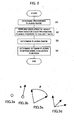
- FIG. 2 is a flow chart showing an overall process in the present embodiment.
- a "provisional placing range” for the robot is determined (Step S1). This is a sort of “first-stage selection”.
- the range determined as the provisional placing range in Step S 1 includes placements (positions/orientations) which is inappropriate in view of various limitations on actual operation (acceleration limit, for example).
- the modifier "provisional” is added for this reason. The specific way of determining the provisional placing range will be described later.
- Step S2 the robot is placed at points within the provisional placing range selected in Step S1, and simulation of operation is performed to collect data for evaluating those placement points from various aspects (Step S2).
- the data items about which data is collected, etc. will be described later.
- Step S3 evaluation is performed from various aspects by comparing the data collected in Step S2 with evaluation criterions for the individual aspects.
- results of evaluation from one or more aspects are evaluated using an evaluation function, and an optimum placement (possibly, optimum placements) is selected.
- An example of the evaluation function, etc. will be described later.
- J Isolve (Q-1P), where Q is a candidate placing position as seen in the world coordinate system, P is a task point as seen in the world coordinate system, J is the axis values of the robot, and Isolve is the inverse kinematics. If J is found at a certain candidate placement point, that candidate placement point is identified as a "solution found point"
- the volumetric region occupied by the robot (including a hand, if any) when the robot is at each of the task points is calculated, using the axis values of the robot obtained corresponding to each of the task points, data about the shape and size of the robot, and if the robot has a hand, data about the shape and size of the hand. If even only a part of the volumetric region occupied by the robot when the robot is at a certain task point is included in the volumetric region occupied by the workpiece or that occupied by the peripheral device, it means that the robot will interfere with the workpiece or the peripheral device at that task point. Hence, the solution found point in question is identified as an "interference causing point".
- the range to which the robot reach from the reachable points is referred to as a "reachable range”. Further, for example the distance from each of provisional placing positions (points) to the boundary of this reachable range may be calculated as an index of a margin for interference. The results of these calculations are stored in the memory and displayed on the screen 13 appropriately as described later.
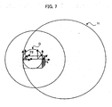
- candidate placement points are determined in the manner described below (see FIG. 7 ).
- a gravity point is obtained from the sequence of task points. Then, the distance between the gravity point and each task point of the sequence of task points is obtained. Then, a sphere G having a center at the obtained gravity point and a radius equal to the longest one of the obtained distances is obtained as a task-point sphere. Further, a robot reachable sphere H, namely a sphere reachable for the robot is defined. The robot reachable sphere is arranged so that it circumscribes the task-point sphere. Then, a sphere having a radius equal to the difference between the diameter of the robot reachable sphere and the radius of the task-point sphere and having a center at the center of the task-point sphere is defined.
- a cuboid enclosing this sphere is defined (the length, width and height of the cuboid define an X-axis direction, a Y-axis direction and a Z-axis direction, respectively).
- a lattice is defined by equally dividing the cuboid in the X-axis direction, in the Y-axis direction and in the Z-axis direction. All the lattice points of the defined lattice are considered as candidate placement points.
- the axis values at each of the task points are obtained.
- the robot has an allowable range for the axis values (operating range), which is determined by the robot model. Generally, operation on the edge of the operating range is not good. Having a margin is preferable.
- an operation margin index is obtained using a function on the basis of the operating range of the axes. The function is so defined that it has value 0 when there is no margin and value 1 when there is a maximum margin.
- a graph of an example of the function is shown in FIG. 8 .
- the definition of the function is also shown in FIG. 8 . Data about this function is stored in advance in the memory of the apparatus and used in the calculation of the operation margin index.
- Step 1 is a sort of first-stage test. Regarding those candidate placing positions which have passed this test (in other words, the provisional placing positions), it is desirable to further check whether they are suitable for the robot's actual operation or not.
- Step 2 data for a sort of second-stage test is collected. Specifically, data for selecting a stricter provisional placing range by reviewing the provisional placing range from the aspect of operational trouble is collected.
- operation programs (sometimes called "TP programs") are fed to the simulation apparatus, and simulation of operation is performed by means of the robot operation/placement arithmetic unit under the condition that the robot is placed at the provisional placing positions one after another.
- TP programs operation programs
- data for evaluating and checking performance items regarding the actual operation is collected.
- the positional data included in the operation programs fed to the apparatus corresponds to the above-mentioned sequence of task points.
- the data collected is as mentioned below.
- Software for calculating this data is generally known, and here it is assumed that the software is installed in the apparatus in advance.
- the data (cycle time, duty, current peak value, energy value, change in acceleration, acceleration peak, change in speed, speed peak) obtained by performing the simulation of operation is stored in the memory. A part or all of the obtained data is displayed on the screen 13 as described later.
- each of the provisional placing positions is evaluated.
- the evaluation is performed, for example as follows: Criterion values (limit values) for all or some of the above data items are predetermined, and those provisional placing positions which satisfy all the predetermined criterion values (limits) are upgraded to "placing positions" (note that the modifier "provisional” is removed).
- criterion values (limit values) for quantities relating to the performance limitations of the robot and not to upgrade those which do not satisfy the criterion values (limit values) to placing positions.
- the following values are set in the apparatus as the criterion values (limit values) to be satisfied.
- placing positions those which satisfy all these criterions are identified as "placing positions”.
- the placing positions identified in Step S3 is evaluated using an appropriate evaluation function to determine an "optimum placement". It is to be noted that there may be more than one "optimum placements". For example, “three best placements" may be selected. Further, generally, which is an optimum placement depends on which aspect is emphasized.
- M is the total number of placing positions.
- ⁇ 1, ⁇ 2,... ⁇ n are ranks of a placing position in question given from a first aspect, a second aspect,...an uth aspect, respectively, each taking a value in the range of 1 to M.
- ⁇ 1, ⁇ 2,... ⁇ u are weighting coefficients for the first aspect, the second aspect,...the uth aspect, respectively, and a value in the range of 0.0 to 1.0 is set for each of those weighting coefficients by an operator.
- the aspects may include the operation margin index obtained in step S1, when necessary, in addition to the data items about which data has been collected in Step S3. The following is an example where the total number M of placing positions is M100.
- First aspect how short the cycle time is.
- Second aspect how small the duty is.
- Third aspect how small the energy value (electric power consumption in one operation cycle) is.
- F( ⁇ ; ⁇ ) ⁇ 1(100 - rank in cycle time shortness ⁇ 1) + ⁇ 2(100 - rank in duty smallness ⁇ 2) + ⁇ 3(100 - rank in energy value smallness ⁇ 3).
- values that are not 0.0 should be set for ⁇ 1, ⁇ 2 and ⁇ 3, individually.
- the setting is performed by an operator looking at the screen 13 and operating the keyboard, for example.
- the results obtained are displayed on the screen 13 in the form of a list as shown in FIG. 9 , for example.
- the displayed list shown in FIG. 9 includes only data about five placements, the displayed list may include all the candidate placing positions, all the provisional placing positions, all the placing positions, or the like if necessary.
- the displayed list shown in FIG. 9 includes the reachability, the cycle time and the margin index, the displayed list may include other items if necessary.
- items such as the current peak value, the acceleration peak value, the energy value, the rank in the energy value (above-mentioned ⁇ 3), the rank in the cycle time (above-mentioned ⁇ 1) and the above-mentioned index of a margin to interference may be displayed in the same screen display or in a separate screen display.
- a range corresponding to all the provisional placing positions that have passed the test in Step S 1 but has not passed the test in Step S3 is displayed in "yellow”, and that a range corresponding to all the placing positions is displayed in "green”, for example.
- the optimum placements selected in Step S4 are displayed as blue blinking points, for example, it is convenient because it allows a person to have an image of the optimum placements before going to an actual working site.
- Step T1 Data about placing environment is specified and set. Like in the above-described embodiment, the data includes the following:
- Step T2 A candidate for a placing range (a set of placing positions) is specified and set.
- An example of the way to specify the candidate is as described above.
- Step T3 The limit value for the operation margin index for the axes of the robot is determined. Also the limit values (criterion values) for evaluation of operation are determined.
- the limit values for evaluation of operation are, for example the limit values for the current peak value, the acceleration (peak of the absolute value) and the speed (peak of the absolute value) as mentioned above.
- Step T4 An operation path and a division number are specified.
- the division number is specified for generating a sequence of task points in the next step.
- Step T5 A sequence of task points is created based on data of the operation path and the specified division number.
- the generation of the sequence of task points may be performed, for example as follows:
- P(t) (Px(t), Py(t), Pz(t)) using a parameter t.
- Step T6 Under the condition that the robot is placed at each of the candidate placing positions, an attempt to solve the inverse kinematics is made regarding the entire sequence of task points, and the candidate placement points at which the solution to the inverse kinematics is found are selected. Further, from these selected candidate placement points, only those which do not allow the robot to interfere with the peripheral device over the entire sequence of task points are selected. Further, regarding each of these selected candidate placement points, the operation margin index for the axes is calculated. Then, only those candidate placing positions regarding which the operation margin index for the axes satisfies the criterion value at all the task points are identified as provisional placing positions, and data about them is stored. It is to be noted that provisional placing positions may be determined considering, in addition to the above conditions, a range that should be excluded from the provisional placing range, if any, on the basis of a user's wish, etc.
- Step T7 Operation programs (sometimes called "TP programs") are fed to the simulation apparatus, and simulation of operation is performed by means of the robot operation/placement arithmetic unit under the condition that the robot is placed at the provisional placing positions one after another.
- TP programs Operation programs
- data for evaluating and checking performance items regarding the actual operation is collected.
- the positional data included in the operation programs fed to the apparatus corresponds to the above-mentioned sequence of task points.
- the data collected is the same as mentioned above. Specifically, it is as follows:
- Step T8 Regarding all the provisional placing positions, whether the limit values for the robot operation are exceeded or not is checked using the data collected by the simulation of operation, etc.
- the current peak value the acceleration (peak of the absolute value) and the speed (peak of the absolute value)
- the values obtained by the simulation and the limit values are compared.
- the provisional placing positions which satisfy the limit values are identified as placing positions, and data about them is stored.
- Step T9 The weighting coefficients ⁇ 1 to ⁇ 3 in the above-mentioned evaluation function F( ⁇ ; ⁇ ) are specified and set. This may be performed in Step T3.
- Step T10 All the placing positions are evaluated using the evaluation function F( ⁇ ; ⁇ ), and an "optimum placement" is determined. As stated above, the number of optimum placements does not have to be one. For example, "three best placements" may be selected.
- Step T11 After the arithmetic processing above is finished, the results obtained are displayed on the screen 13 in the form of a list as shown in FIG. 9 , for example. As stated above, it may be so arranged that a range corresponding to all the provisional placing positions that have passed the test in Step T6 but has not passed the test in Step T8 is displayed in "yellow", and that a range corresponding to all the placing positions is displayed in "green", for example. Further, if the optimum placements selected in Step T10 are displayed as blue blinking points, for example, it is convenient because it allows a person to have an image of the optimum placements before going to an actual working site.
Landscapes
- Engineering & Computer Science (AREA)
- Robotics (AREA)
- Mechanical Engineering (AREA)
- Numerical Control (AREA)
- Manipulator (AREA)
Claims (10)
- Offline-Simulationsvorrichtung (10) für einen Roboter, die eine Operation eines Roboters (1) simuliert, der mit einem Werkstück (36) und einer Peripherievorrichtung (37) in einem dreidimensionalen Raum angeordnet ist, indem gleichzeitig dreidimensionale Modelle des Roboters (1), des Werkstücks (36) und der Peripherievorrichtung (37) auf einem Bildschirm (13) angezeigt werden, umfassend:ein Mittel, das feststellt, ob eine Lösung der inversen Bewegungsgleichungen des Roboters (1) zum Erreichen einer voreingestellten Folge von Aufgabenpunkten zum Ausführen von Aufgaben am Werkstück (36) für jeden Satz von in Frage kommenden Anordnungspunkten möglich ist, wobei jeder in Frage kommende Anordnungspunkt, für den festgestellt wird, dass es möglich ist, die inversen Bewegungsgleichungen zu lösen, als gefundener Lösungspunkt ermittelt wird;ein Mittel, das für jeden gefundenen Lösungspunkt feststellt, ob der Roboter (1) an dem Werkstück (36) oder der Peripherievorrichtung (37) anstößt, wenn der Roboter (1) die voreingestellte Folge von Aufgabenpunkten erreicht, um dort Aufgaben am Werkstück (36) auszuführen, wobei jeder gefundene Lösungspunkt, für den festgestellt wird, dass der Roboter (1) nicht an dem Werkstück (36) oder der Peripherievorrichtung (37) anstößt, als erreichbarer Punkt festgelegt wird;ein Mittel zum Gewinnen eines Index, der einen Operations-Sicherheitsabstand des Roboters (1) an jedem Aufgabenpunkt darstellt, wenn der Roboter an jedem der erreichbaren Punkte angeordnet wird;ein Mittel zum Feststellen, ob der Operations-Sicherheitsabstand einen Kriteriumswert für jeden erreichbaren Punkt erfüllt, wobei jeder erreichbare Punkt, für den festgestellt wird, dass der Operations-Sicherheitsabstand den Kriteriumswert erfüllt, als provisorische Anordnungsposition festgelegt wird;ein Mittel zum Simulieren einer Operation des Roboters (1) an jeder provisorischen Anordnungsposition gemäß einem Operationsprogramm, damit man mit Hilfe einer Beurteilungsfunktion einen Beurteilungswert hinsichtlich des Operationsverhaltens des Roboters (1) gewinnt, und zum Feststellen, ob der Beurteilungswert vorbestimmte Kriteriumswerte erfüllt, wobei jede provisorische Anordnungsposition, für die festgestellt wird, dass der Beurteilungswert die vorbestimmten Kriteriumswerte erfüllt, als Anordnungsposition festgelegt wird;ein Mittel, das mindestens eine bestmögliche Anordnungsposition aus den Anordnungspositionen ermittelt; undein Mittel, das die bestmöglichen Anordnungspositionen und die gewonnenen Indizes für die jeweiligen bestmöglichen Anordnungspositionen auf dem Bildschirm (13) darstellt.
- Offline-Simulationsvorrichtung (10) für einen Roboter nach Anspruch 1, wobei jedem Aufgabenpunkt entweder eine dreidimensionale Position oder eine Kombination aus der dreidimensionalen Position und einem Richtungsvektor oder eine Kombination aus der dreidimensionalen Position und einer Orientierung zugewiesen wird, damit der Roboter (1) die Aufgabe an dem Werkstück (36) ausführen kann.
- Offline-Simutationsvorrichtung (10) für einen Roboter nach Anspruch 1, wobei die Beurteilungsfunktion dafür eingerichtet ist, das Operationsverhalten des Roboters (1) bezogen auf eine Zykluszeit zu beurteilen.
- Offline-Simulationsvorrichtung (10) für einen Roboter nach Anspruch 1, wobei die Beurteilungsfunktion dafür eingerichtet ist, das Operationsverhalten des Roboters (1) bezogen auf die Leistung zu beurteilen.
- Offline-Simulationsvorrichtung (10) für einen Roboter nach Anspruch 1, wobei die Beurteilungsfunktion dafür eingerichtet ist, das Operationsverhalten des Roboters (1) bezogen auf die Energie zu beurteilen.
- Offline-Simulationsvorrichtung (10) für einen Roboter, die eine Operation eines Roboters (1) simuliert, der mit einem Werkstück (36) und einer Peripherievorrichtung (37) in einem dreidimensionalen Raum angeordnet ist, indem gleichzeitig dreidimensionale Modelle des Roboters (1), des Werkstücks (36) und der Peripherievorrichtung (37) auf einem Bildschirm (13) angezeigt werden, umfassend:ein Mittel, das feststellt, ob eine Lösung der inversen Bewegungsgleichungen des Roboters (1) zum Erreichen eines voreingestellten Roboter-Operationswegs zum Ausführen von Aufgaben am Werkstück (36) für jeden Satz von in Frage kommenden Anordnungspunkten möglich ist, wobei jeder in Frage kommende Anordnungspunkt, für den festgestellt wird, dass es möglich ist, die inversen Bewegungsgleichungen zu lösen, als gefundener Lösungspunkt ermittelt wird;ein Mittel, das für jeden gefundenen Lösungspunkt feststellt, ob der Roboter (1) an dem Werkstück (36) oder der Peripherievorrichtung (37) anstößt, wenn der Roboter den voreingestellten Roboter-Operationsweg erreicht, um Aufgaben am Werkstück (36) auszuführen, wobei jeder gefundene Lösungspunkt, für den festgestellt wird, dass der Roboter (1) nicht an dem Werkstück (36) oder der Peripherievorrichtung (37) anstößt, als erreichbarer Punkt festgelegt wird;ein Mittel zum Gewinnen eines Index, der einen Operations-Sicherheitsabstand des Roboters (1) auf dem Operationsweg darstellt, wenn der Roboter an jedem der erreichbaren Punkte angeordnet wird;ein Mittel zum Feststellen, ob der Operations-Sicherheitsabstand einen Kriteriumswert für jeden erreichbaren Punkt erfüllt, wobei jeder erreichbare Punkt, für den festgestellt wird, dass der Operations-Sicherheitsabstand den Kriteriumswert erfüllt, als provisorische Anordnungsposition festgelegt wird;ein Mittel zum Simulieren einer Operation des Roboters (1) an jeder provisorischen Anordnungsposition gemäß einem Operationsprogramm, damit man mit Hilfe einer Beurteilungsfunktion einen Beurteilungswert hinsichtlich des Operationsverhaltens des Roboters (1) gewinnt, und zum Feststellen, ob der Beurteilungswert vorbestimmte Kriteriumswerte erfüllt, wobei jede provisorische Anordnungsposition, für die festgestellt wird, dass der Beurteilungswert die vorbestimmten Kriteriumswerte erfüllt, als Anordnungsposition festgelegt wird;ein Mittel, das mindestens eine bestmögliche Anordnungsposition aus den Anordnungspositionen ermittelt; undein Mittel, das die bestmöglichen Anordnungspositionen und die gewonnenen Indizes für die jeweiligen bestmöglichen Anordnungspositionen auf dem Bildschirm (13) darstellt.
- Offline-Simulationsvorrichtung (10) für einen Roboter nach Anspruch 6, wobei dem Operationsweg entweder ein Richtungsvektor oder eine Orientierung zugewiesen wird, damit der Roboter (1) die Aufgabe an dem Werkstück (36) ausführen kann.
- Offline-Simulationsvorrichtung (10) für einen Roboter nach Anspruch 6, wobei die Beurteilungsfunktion dafür eingerichtet ist, das Operationsverhalten des Roboters (1) bezogen auf eine Zykluszeit zu beurteilen.
- Offline-Simulationsvorrichtung (10) für einen Roboter nach Anspruch 6, wobei die Beurteilungsfunktion dafür eingerichtet ist, das Operationsverhalten des Roboters (1) bezogen auf die Leistung zu beurteilen.
- Offline-Simulationsvorrichtung (10) für einen Roboter nach Anspruch 6, wobei die Beurteilungsfunktion dafür eingerichtet ist, das Operationsverhalten des Roboters (1) bezogen auf die Energie zu beurteilen.
Applications Claiming Priority (2)
| Application Number | Priority Date | Filing Date | Title |
|---|---|---|---|
| JP2003270606 | 2003-07-03 | ||
| JP2003270606A JP3797986B2 (ja) | 2003-07-03 | 2003-07-03 | ロボットオフラインシミュレーション装置 |
Publications (3)
| Publication Number | Publication Date |
|---|---|
| EP1498792A2 EP1498792A2 (de) | 2005-01-19 |
| EP1498792A3 EP1498792A3 (de) | 2009-04-08 |
| EP1498792B1 true EP1498792B1 (de) | 2010-12-15 |
Family
ID=33475535
Family Applications (1)
| Application Number | Title | Priority Date | Filing Date |
|---|---|---|---|
| EP04254016A Expired - Lifetime EP1498792B1 (de) | 2003-07-03 | 2004-07-02 | Vorrichtung zur Off- line Simulation von robotischen Arbeitsgängen |
Country Status (4)
| Country | Link |
|---|---|
| US (1) | US7512459B2 (de) |
| EP (1) | EP1498792B1 (de) |
| JP (1) | JP3797986B2 (de) |
| DE (1) | DE602004030517D1 (de) |
Cited By (1)
| Publication number | Priority date | Publication date | Assignee | Title |
|---|---|---|---|---|
| US11325257B2 (en) | 2018-11-16 | 2022-05-10 | Fanuc Corporation | Operation program creation device |
Families Citing this family (47)
| Publication number | Priority date | Publication date | Assignee | Title |
|---|---|---|---|---|
| US6493608B1 (en) * | 1999-04-07 | 2002-12-10 | Intuitive Surgical, Inc. | Aspects of a control system of a minimally invasive surgical apparatus |
| JP4266946B2 (ja) * | 2005-03-17 | 2009-05-27 | ファナック株式会社 | オフライン教示装置 |
| JP4829151B2 (ja) * | 2005-07-25 | 2011-12-07 | ファナック株式会社 | ロボットプログラム評価・修正方法及びロボットプログラム評価・修正装置 |
| JP3946753B2 (ja) | 2005-07-25 | 2007-07-18 | ファナック株式会社 | ロボットプログラム評価・修正方法及びロボットプログラム評価・修正装置 |
| JP2007125645A (ja) * | 2005-11-04 | 2007-05-24 | Hitachi Ltd | ロボット動作編集システム |
| JP4730337B2 (ja) * | 2007-05-28 | 2011-07-20 | トヨタ自動車株式会社 | ロボットの設置位置決定装置及びロボットの設置位置決定方法 |
| JP4798552B2 (ja) * | 2007-11-14 | 2011-10-19 | 株式会社安川電機 | ロボットの領域監視方法および制御装置 |
| JP4347386B2 (ja) * | 2008-01-23 | 2009-10-21 | ファナック株式会社 | 加工用ロボットプラグラムの作成装置 |
| WO2009103335A1 (en) * | 2008-02-20 | 2009-08-27 | Abb Research Ltd. | Method and system for optimizing the layout of a robot work cell |
| JP5103237B2 (ja) * | 2008-03-25 | 2012-12-19 | 株式会社神戸製鋼所 | ロボットの動作余裕量演算表示方法及びその装置 |
| JP2009269134A (ja) * | 2008-05-08 | 2009-11-19 | Denso Wave Inc | 視覚検査装置のシミュレーション装置 |
| JP2009274148A (ja) * | 2008-05-12 | 2009-11-26 | Kanto Auto Works Ltd | シミュレーション装置 |
| JP5502348B2 (ja) * | 2009-03-12 | 2014-05-28 | ファナック株式会社 | シミュレーション方法 |
| JP5338408B2 (ja) * | 2009-03-19 | 2013-11-13 | 株式会社デンソーウェーブ | ロボットシミュレータ |
| JP4571225B1 (ja) * | 2009-05-27 | 2010-10-27 | ファナック株式会社 | 消費電力推定装置 |
| JP5513146B2 (ja) * | 2010-01-29 | 2014-06-04 | 株式会社デンソーウェーブ | ロボットシミュレータ |
| US9102012B2 (en) * | 2011-06-22 | 2015-08-11 | Caterpillar Inc. | Method and system for determining welding sequences |
| JP2013066954A (ja) * | 2011-09-21 | 2013-04-18 | Seiko Epson Corp | ロボット及びロボットの制御方法 |
| JP5513661B2 (ja) * | 2013-05-09 | 2014-06-04 | ファナック株式会社 | 付加軸付きロボットのオフラインプログラム作成装置 |
| CN103390101B (zh) * | 2013-07-15 | 2016-08-10 | 哈尔滨工程大学 | 串联形式机器人的逆运动学通用求解方法 |
| CN105980940B (zh) | 2014-01-28 | 2019-01-01 | Abb瑞士股份有限公司 | 用于优化机器人单元的性能的方法和装置 |
| US9922144B2 (en) * | 2014-03-26 | 2018-03-20 | Siemens Industry Software Ltd. | Energy and cycle time efficiency based method for robot positioning |
| US9283678B2 (en) * | 2014-07-16 | 2016-03-15 | Google Inc. | Virtual safety cages for robotic devices |
| JP2016221166A (ja) * | 2015-06-03 | 2016-12-28 | 株式会社デンソー | 医療行為支援システム |
| EP3387496A4 (de) * | 2015-12-11 | 2019-07-31 | ABB Schweiz AG | Verfahren offline-programmierung eines roboters und vorrichtung unter verwendung der verfahrens |
| CN106980751B (zh) * | 2017-02-27 | 2019-08-13 | 浙江大学 | 一种含双c轴的六轴自动化制孔锪窝机床的运动学反解方法 |
| US10455222B2 (en) * | 2017-03-30 | 2019-10-22 | Intel Corporation | Technologies for autonomous three-dimensional modeling |
| US10676022B2 (en) | 2017-12-27 | 2020-06-09 | X Development Llc | Visually indicating vehicle caution regions |
| TWI822729B (zh) | 2018-02-06 | 2023-11-21 | 美商即時機器人股份有限公司 | 用於儲存一離散環境於一或多個處理器之一機器人之運動規劃及其改良操作之方法及設備 |
| EP3769174B1 (de) | 2018-03-21 | 2022-07-06 | Realtime Robotics, Inc. | Bewegungsplanung eines roboters für verschiedene umgebungen und aufgaben und verbesserter betrieb davon |
| CN108804098A (zh) * | 2018-05-23 | 2018-11-13 | 骅星科技发展有限公司 | 一种点击拖动式编程控制方法及其软件系统 |
| DE102019102803B4 (de) * | 2019-02-05 | 2022-02-17 | Franka Emika Gmbh | Ausrichten zweier Roboterarme zueinander |
| TWI873149B (zh) | 2019-06-24 | 2025-02-21 | 美商即時機器人股份有限公司 | 用於多個機械手臂於共用工作空間中之移動規劃系統及方法 |
| CN114667110A (zh) | 2019-10-29 | 2022-06-24 | 威博外科公司 | 用于利用患者模型和可定制的手术室模拟外科工作流的虚拟现实系统 |
| DE102019134664B4 (de) * | 2019-12-17 | 2021-07-29 | Franka Emika Gmbh | Konfigurieren eines Robotermanipulators beim Aufstellen |
| TWI887329B (zh) * | 2020-01-22 | 2025-06-21 | 美商即時機器人股份有限公司 | 於多機器人操作環境中之機器人之建置之方法及系統 |
| JP2023518071A (ja) | 2020-03-18 | 2023-04-27 | リアルタイム ロボティクス, インコーポレーテッド | ロボットの動作計画に有用なロボット操作環境のデジタル表現 |
| CN112428275B (zh) * | 2020-11-30 | 2022-04-19 | 深圳市优必选科技股份有限公司 | 机器人运动规划方法、装置、可移动机器人及存储介质 |
| JP7435434B2 (ja) | 2020-12-22 | 2024-02-21 | 株式会社デンソー | レイアウト生成装置、レイアウト生成方法およびレイアウト生成プログラム |
| JP7597369B2 (ja) * | 2021-03-31 | 2024-12-10 | Johnan株式会社 | ロボット制御システム、制御装置、およびロボットの制御方法 |
| WO2022269739A1 (ja) * | 2021-06-22 | 2022-12-29 | 株式会社Fuji | ロボットの可動範囲表示方法およびシミュレーションシステム |
| JP7639650B2 (ja) | 2021-10-21 | 2025-03-05 | 株式会社デンソー | 経路生成装置、経路生成方法および経路生成プログラム |
| US12202149B2 (en) * | 2021-12-10 | 2025-01-21 | Autodesk, Inc. | Techniques for robotic workcell design |
| WO2025013784A1 (ja) * | 2023-07-07 | 2025-01-16 | 京セラ株式会社 | 処理装置、プログラム、表示装置及び処理システム |
| WO2025099944A1 (ja) * | 2023-11-10 | 2025-05-15 | ファナック株式会社 | ロボットプログラミング装置 |
| WO2025099925A1 (ja) * | 2023-11-10 | 2025-05-15 | ファナック株式会社 | ロボットプログラミング装置 |
| CN118608740B (zh) * | 2024-06-12 | 2025-07-25 | 盐城皓月信息科技有限公司 | 一种基于物联网的生产任务管控方法 |
Family Cites Families (13)
| Publication number | Priority date | Publication date | Assignee | Title |
|---|---|---|---|---|
| US5155423A (en) * | 1986-02-18 | 1992-10-13 | Robotics Research Corporation | Industrial robot with servo |
| JP3114875B2 (ja) | 1990-11-29 | 2000-12-04 | 株式会社日立製作所 | レイアウト設計方法 |
| JPH0699375A (ja) * | 1992-09-18 | 1994-04-12 | Kawasaki Heavy Ind Ltd | ロボット操作訓練装置 |
| JPH06348769A (ja) | 1993-06-14 | 1994-12-22 | Omron Corp | 機械構成/機械配置決定装置またはその方法 |
| JP2984218B2 (ja) | 1996-07-23 | 1999-11-29 | 川崎重工業株式会社 | 複数台ロボットの作業計画方法 |
| FR2764838B1 (fr) * | 1997-06-20 | 2000-06-02 | Deutsch Zentr Luft & Raumfahrt | Procede de commande d'un manipulateur |
| JPH1177569A (ja) * | 1997-09-10 | 1999-03-23 | Honda Motor Co Ltd | オフラインティーチング装置 |
| JP3655083B2 (ja) * | 1998-02-25 | 2005-06-02 | 富士通株式会社 | ロボットの位置決めを行うインタフェース装置 |
| JP2000141184A (ja) * | 1998-11-04 | 2000-05-23 | Honda Motor Co Ltd | 作業ロボットのレイアウトシミュレーション方法 |
| US6526373B1 (en) | 1999-10-08 | 2003-02-25 | Dassault Systemes | Optimization tool for robot placement |
| WO2002016091A1 (en) * | 2000-08-25 | 2002-02-28 | Janome Sewing Machine Co., Ltd. | Robot |
| JPWO2002037341A1 (ja) | 2000-10-27 | 2004-03-11 | 三菱電機株式会社 | 設備計画支援方法、設備計画支援システムのサーバーコンピュータ及び設備計画支援システムのクライアントコンピュータ |
| JP3673749B2 (ja) * | 2001-11-12 | 2005-07-20 | ファナック株式会社 | シミュレーション装置 |
-
2003
- 2003-07-03 JP JP2003270606A patent/JP3797986B2/ja not_active Expired - Fee Related
-
2004
- 2004-07-02 EP EP04254016A patent/EP1498792B1/de not_active Expired - Lifetime
- 2004-07-02 US US10/882,240 patent/US7512459B2/en active Active
- 2004-07-02 DE DE602004030517T patent/DE602004030517D1/de not_active Expired - Lifetime
Cited By (2)
| Publication number | Priority date | Publication date | Assignee | Title |
|---|---|---|---|---|
| US11325257B2 (en) | 2018-11-16 | 2022-05-10 | Fanuc Corporation | Operation program creation device |
| DE102019130008B4 (de) | 2018-11-16 | 2022-09-29 | Fanuc Corporation | Tätigkeitsprogrammerstellungseinrichtung |
Also Published As
| Publication number | Publication date |
|---|---|
| EP1498792A2 (de) | 2005-01-19 |
| JP3797986B2 (ja) | 2006-07-19 |
| JP2005022062A (ja) | 2005-01-27 |
| US20050004709A1 (en) | 2005-01-06 |
| US7512459B2 (en) | 2009-03-31 |
| EP1498792A3 (de) | 2009-04-08 |
| DE602004030517D1 (de) | 2011-01-27 |
Similar Documents
| Publication | Publication Date | Title |
|---|---|---|
| US7512459B2 (en) | Robot off-line simulation apparatus | |
| US8401698B2 (en) | Method for optimising the performance of a robot | |
| EP1527850B1 (de) | Simulationsvorrichtung | |
| US7027963B2 (en) | Simulation system | |
| US8428768B2 (en) | Method and device for composite machining based on tool-path pattern types with tool axis orientation rules | |
| JP4210056B2 (ja) | 工具経路の作成装置及び方法 | |
| EP4036520B1 (de) | Automatische erzeugung eines sondenpfades zur oberflächeninspektion und teilausrichtung | |
| JP5142880B2 (ja) | 加工パラメータ最適化装置、加工パラメータ最適化方法およびプログラム | |
| Wojtynek et al. | Assisted planning and setup of collaborative robot applications in modular production systems | |
| EP1398683B1 (de) | System und Verfahren zur Erzeugung von numerisch gesteurten Werkzeugbahnen auf einem Festkörpermodell | |
| Sarma et al. | Rapid product realization from detail design | |
| Shinde et al. | Synthesising of flexural spindle head micro drilling machine tool in PLM environment | |
| JP4225422B2 (ja) | Nc加工システム、ncデータ作成装置、ncデータ作成システム、ncデータ作成方法及びncデータ作成プログラム | |
| Glavonjic et al. | Functional simulator of 3-axis parallel kinematic milling machine | |
| Lee et al. | Development of a virtual machining and inspection system for ultra-precision diamond turning | |
| US6681144B1 (en) | Process and system for working a workpiece through numerically controlled machine tools | |
| Chou | Automated planning and design of fixtures for complex parts | |
| Lu et al. | Application of an iterative learning control algorithm to volumetric error compensation for CNC machines | |
| Lindberget | Automatic generation of robot targets: A first step towards a flexible robotic solution for cutting customized mesh tray | |
| Kongiranda Ganapathi et al. | Design Automation For CNC Machining: A case study for generating CNC codes from geometric CAD models | |
| US20240176322A1 (en) | Machining Fixture Force Balancing | |
| Ray | Design of new high speed machining machines | |
| Okafor et al. | Development of web-based virtual CNC milling machine and machining process simulation and learning | |
| Pavlakos | Influences and impact of the design approach on an open architecture controller | |
| RUOKONEN | ENVIRONMENT-AND TASK-DRIVEN TOOL FOR SELECTING IN-DUSTRIAL ROBOTS |
Legal Events
| Date | Code | Title | Description |
|---|---|---|---|
| PUAI | Public reference made under article 153(3) epc to a published international application that has entered the european phase |
Free format text: ORIGINAL CODE: 0009012 |
|
| AK | Designated contracting states |
Kind code of ref document: A2 Designated state(s): AT BE BG CH CY CZ DE DK EE ES FI FR GB GR HU IE IT LI LU MC NL PL PT RO SE SI SK TR |
|
| AX | Request for extension of the european patent |
Extension state: AL HR LT LV MK |
|
| PUAL | Search report despatched |
Free format text: ORIGINAL CODE: 0009013 |
|
| AK | Designated contracting states |
Kind code of ref document: A3 Designated state(s): AT BE BG CH CY CZ DE DK EE ES FI FR GB GR HU IE IT LI LU MC NL PL PT RO SE SI SK TR |
|
| AX | Request for extension of the european patent |
Extension state: AL HR LT LV MK |
|
| 17P | Request for examination filed |
Effective date: 20090803 |
|
| 17Q | First examination report despatched |
Effective date: 20090826 |
|
| AKX | Designation fees paid |
Designated state(s): DE |
|
| GRAP | Despatch of communication of intention to grant a patent |
Free format text: ORIGINAL CODE: EPIDOSNIGR1 |
|
| GRAS | Grant fee paid |
Free format text: ORIGINAL CODE: EPIDOSNIGR3 |
|
| GRAA | (expected) grant |
Free format text: ORIGINAL CODE: 0009210 |
|
| AK | Designated contracting states |
Kind code of ref document: B1 Designated state(s): DE |
|
| REF | Corresponds to: |
Ref document number: 602004030517 Country of ref document: DE Date of ref document: 20110127 Kind code of ref document: P |
|
| RAP2 | Party data changed (patent owner data changed or rights of a patent transferred) |
Owner name: FANUC CORPORATION |
|
| PLBE | No opposition filed within time limit |
Free format text: ORIGINAL CODE: 0009261 |
|
| STAA | Information on the status of an ep patent application or granted ep patent |
Free format text: STATUS: NO OPPOSITION FILED WITHIN TIME LIMIT |
|
| 26N | No opposition filed |
Effective date: 20110916 |
|
| REG | Reference to a national code |
Ref country code: DE Ref legal event code: R097 Ref document number: 602004030517 Country of ref document: DE Effective date: 20110916 |
|
| REG | Reference to a national code |
Ref country code: DE Ref legal event code: R082 Ref document number: 602004030517 Country of ref document: DE Representative=s name: HL KEMPNER PATENTANWAELTE, SOLICITORS (ENGLAND, DE Ref country code: DE Ref legal event code: R082 Ref document number: 602004030517 Country of ref document: DE Representative=s name: HL KEMPNER PATENTANWALT, RECHTSANWALT, SOLICIT, DE |
|
| PGFP | Annual fee paid to national office [announced via postgrant information from national office to epo] |
Ref country code: DE Payment date: 20230531 Year of fee payment: 20 |