EP1527850B1 - Simulationsvorrichtung - Google Patents
Simulationsvorrichtung Download PDFInfo
- Publication number
- EP1527850B1 EP1527850B1 EP04025427A EP04025427A EP1527850B1 EP 1527850 B1 EP1527850 B1 EP 1527850B1 EP 04025427 A EP04025427 A EP 04025427A EP 04025427 A EP04025427 A EP 04025427A EP 1527850 B1 EP1527850 B1 EP 1527850B1
- Authority
- EP
- European Patent Office
- Prior art keywords
- robot
- image capturing
- screen
- display
- visual field
- Prior art date
- Legal status (The legal status is an assumption and is not a legal conclusion. Google has not performed a legal analysis and makes no representation as to the accuracy of the status listed.)
- Expired - Lifetime
Links
- 238000004088 simulation Methods 0.000 title claims description 64
- 230000000007 visual effect Effects 0.000 claims description 96
- 238000012937 correction Methods 0.000 claims description 35
- 230000015654 memory Effects 0.000 claims description 5
- 230000002093 peripheral effect Effects 0.000 claims description 5
- 238000001514 detection method Methods 0.000 description 40
- 238000002360 preparation method Methods 0.000 description 12
- 238000004364 calculation method Methods 0.000 description 6
- 238000000034 method Methods 0.000 description 6
- 238000012545 processing Methods 0.000 description 5
- 230000006870 function Effects 0.000 description 4
- 238000004891 communication Methods 0.000 description 2
- 238000012790 confirmation Methods 0.000 description 2
- 238000010586 diagram Methods 0.000 description 2
- 238000011156 evaluation Methods 0.000 description 2
- 238000012546 transfer Methods 0.000 description 2
- 238000007792 addition Methods 0.000 description 1
- 230000003190 augmentative effect Effects 0.000 description 1
- 238000013500 data storage Methods 0.000 description 1
- 238000012217 deletion Methods 0.000 description 1
- 230000037430 deletion Effects 0.000 description 1
- 238000005516 engineering process Methods 0.000 description 1
- 239000004973 liquid crystal related substance Substances 0.000 description 1
- 230000003287 optical effect Effects 0.000 description 1
- 230000002459 sustained effect Effects 0.000 description 1
- 210000000707 wrist Anatomy 0.000 description 1
Images


Classifications
-
- G—PHYSICS
- G05—CONTROLLING; REGULATING
- G05B—CONTROL OR REGULATING SYSTEMS IN GENERAL; FUNCTIONAL ELEMENTS OF SUCH SYSTEMS; MONITORING OR TESTING ARRANGEMENTS FOR SUCH SYSTEMS OR ELEMENTS
- G05B19/00—Programme-control systems
- G05B19/02—Programme-control systems electric
- G05B19/18—Numerical control [NC], i.e. automatically operating machines, in particular machine tools, e.g. in a manufacturing environment, so as to execute positioning, movement or co-ordinated operations by means of programme data in numerical form
- G05B19/406—Numerical control [NC], i.e. automatically operating machines, in particular machine tools, e.g. in a manufacturing environment, so as to execute positioning, movement or co-ordinated operations by means of programme data in numerical form characterised by monitoring or safety
- G05B19/4069—Simulating machining process on screen
-
- B—PERFORMING OPERATIONS; TRANSPORTING
- B25—HAND TOOLS; PORTABLE POWER-DRIVEN TOOLS; MANIPULATORS
- B25J—MANIPULATORS; CHAMBERS PROVIDED WITH MANIPULATION DEVICES
- B25J9/00—Programme-controlled manipulators
- B25J9/16—Programme controls
- B25J9/1656—Programme controls characterised by programming, planning systems for manipulators
- B25J9/1671—Programme controls characterised by programming, planning systems for manipulators characterised by simulation, either to verify existing program or to create and verify new program, CAD/CAM oriented, graphic oriented programming systems
-
- G—PHYSICS
- G05—CONTROLLING; REGULATING
- G05B—CONTROL OR REGULATING SYSTEMS IN GENERAL; FUNCTIONAL ELEMENTS OF SUCH SYSTEMS; MONITORING OR TESTING ARRANGEMENTS FOR SUCH SYSTEMS OR ELEMENTS
- G05B2219/00—Program-control systems
- G05B2219/30—Nc systems
- G05B2219/32—Operator till task planning
- G05B2219/32351—Visual, graphical animation of process
-
- G—PHYSICS
- G05—CONTROLLING; REGULATING
- G05B—CONTROL OR REGULATING SYSTEMS IN GENERAL; FUNCTIONAL ELEMENTS OF SUCH SYSTEMS; MONITORING OR TESTING ARRANGEMENTS FOR SUCH SYSTEMS OR ELEMENTS
- G05B2219/00—Program-control systems
- G05B2219/30—Nc systems
- G05B2219/39—Robotics, robotics to robotics hand
- G05B2219/39031—Use of model for robot and for measuring device
-
- G—PHYSICS
- G05—CONTROLLING; REGULATING
- G05B—CONTROL OR REGULATING SYSTEMS IN GENERAL; FUNCTIONAL ELEMENTS OF SUCH SYSTEMS; MONITORING OR TESTING ARRANGEMENTS FOR SUCH SYSTEMS OR ELEMENTS
- G05B2219/00—Program-control systems
- G05B2219/30—Nc systems
- G05B2219/40—Robotics, robotics mapping to robotics vision
- G05B2219/40003—Move end effector so that image center is shifted to desired position
-
- G—PHYSICS
- G05—CONTROLLING; REGULATING
- G05B—CONTROL OR REGULATING SYSTEMS IN GENERAL; FUNCTIONAL ELEMENTS OF SUCH SYSTEMS; MONITORING OR TESTING ARRANGEMENTS FOR SUCH SYSTEMS OR ELEMENTS
- G05B2219/00—Program-control systems
- G05B2219/30—Nc systems
- G05B2219/40—Robotics, robotics mapping to robotics vision
- G05B2219/40121—Trajectory planning in virtual space
-
- G—PHYSICS
- G05—CONTROLLING; REGULATING
- G05B—CONTROL OR REGULATING SYSTEMS IN GENERAL; FUNCTIONAL ELEMENTS OF SUCH SYSTEMS; MONITORING OR TESTING ARRANGEMENTS FOR SUCH SYSTEMS OR ELEMENTS
- G05B2219/00—Program-control systems
- G05B2219/30—Nc systems
- G05B2219/40—Robotics, robotics mapping to robotics vision
- G05B2219/40131—Virtual reality control, programming of manipulator
-
- G—PHYSICS
- G05—CONTROLLING; REGULATING
- G05B—CONTROL OR REGULATING SYSTEMS IN GENERAL; FUNCTIONAL ELEMENTS OF SUCH SYSTEMS; MONITORING OR TESTING ARRANGEMENTS FOR SUCH SYSTEMS OR ELEMENTS
- G05B2219/00—Program-control systems
- G05B2219/30—Nc systems
- G05B2219/40—Robotics, robotics mapping to robotics vision
- G05B2219/40314—Simulation of program locally before remote operation
-
- G—PHYSICS
- G05—CONTROLLING; REGULATING
- G05B—CONTROL OR REGULATING SYSTEMS IN GENERAL; FUNCTIONAL ELEMENTS OF SUCH SYSTEMS; MONITORING OR TESTING ARRANGEMENTS FOR SUCH SYSTEMS OR ELEMENTS
- G05B2219/00—Program-control systems
- G05B2219/30—Nc systems
- G05B2219/40—Robotics, robotics mapping to robotics vision
- G05B2219/40323—Modeling robot environment for sensor based robot system
-
- Y—GENERAL TAGGING OF NEW TECHNOLOGICAL DEVELOPMENTS; GENERAL TAGGING OF CROSS-SECTIONAL TECHNOLOGIES SPANNING OVER SEVERAL SECTIONS OF THE IPC; TECHNICAL SUBJECTS COVERED BY FORMER USPC CROSS-REFERENCE ART COLLECTIONS [XRACs] AND DIGESTS
- Y02—TECHNOLOGIES OR APPLICATIONS FOR MITIGATION OR ADAPTATION AGAINST CLIMATE CHANGE
- Y02P—CLIMATE CHANGE MITIGATION TECHNOLOGIES IN THE PRODUCTION OR PROCESSING OF GOODS
- Y02P90/00—Enabling technologies with a potential contribution to greenhouse gas [GHG] emissions mitigation
- Y02P90/02—Total factory control, e.g. smart factories, flexible manufacturing systems [FMS] or integrated manufacturing systems [IMS]
Definitions
- the present invention relates to a simulation apparatus for a robot system including a visual sensor having an image capturing means and a robot, more particularly relates to a simulation apparatus useful when preparing an operation program including robot movement and detection by the visual sensor off line and evaluating, correcting, editing, etc. the program finished being prepared or in the process of preparation off line.
- a simulation apparatus arranging and displaying on a screen three-dimensional models of a robot, workpiece, and peripheral equipment and simulating robot operation in accordance with designated robot movement commands etc.
- the simulation apparatus is used when preparing an operation program for the robot off line or evaluating, correcting, editing, etc. the program prepared off line.
- simulation apparatus when trying to prepare, correct, edit, etc. a program off line at a location where the actual machinery is not deployed (for example, an office), simulation relating to the visual sensor has been almost impossible.
- the visual sensor uses for image capturing.
- the image capturing means for example, digital CCD camera, same below.
- the practice has been to actually mount an image capturing means on a robot on-site, operate the visual sensor to obtain an image while changing the position and orientation of the robot, and check the resultant image.
- the practice has been to operate the robot on-site and perform the work by trial and error while viewing the captured image. Further, determining where in the operation program of the robot to insert the visual sensor detection command also required trial and error.
- the robot is controlled by a guiding system able to transfer robot programs to the robot control.
- the guiding system is sustained by a sensor system and a 3D simulation system.
- the guiding system controls the simulation system and the sensor system to guarantee a sensible cooperation of all involved components.
- Robot programs can be generated automatically with planning algorithms implemented in the simulation system.
- the sensor system comprises a CCD camera integrated in the robot's wrist flange.
- the CCD camera is used to determine a location of an object.
- a reference pattern for the object to be recognized is provided by the simulation system taking a photo of the simulated object with a virtual camera. Due the calculation of the position deviation, the location of the simulated object then can be adjusted.
- the present invention provides a simulation apparatus able to reduce or eliminate the various inconveniences and drop in work efficiency which had arisen when preparing an operation program off line or evaluating, correcting, editing, etc. the program prepared off line for a robot system including a visual sensor.
- the present invention provides a simulation apparatus arranging and simultaneously displaying on a screen three-dimensional models of at least a robot, workpiece, and image capturing means of a visual sensor and simulating operation of the robot, wherein provision is made of a visual field display means for displaying the visual field of the image capturing means on the screen by a three-dimensional shape. Due to this, the three-dimensional shape (visual volume) of the visual field of the image capturing means can be easily confirmed on the screen.
- the three-dimensional shape of the visual field is typically a square pyramid.
- the present invention provides a simulation apparatus arranging and simultaneously displaying on a screen three-dimensional models of at least a robot, workpiece, and image capturing means of a visual sensor and simulating operation of the robot, wherein provision is made of a visual field display means 41 for displaying the visual field of the image capturing means (2) on the screen by a three-dimensional shape. Due to this, the three-dimensional shape (visual volume) of the visual field of the image capturing means (2) can be easily confirmed on the screen.
- the three-dimensional shape of the visual field is typically a square pyramid (31).
- the present invention may also provide an image display means 42 for displaying an image captured by the image capturing means (2) in the visual field on a screen. Due to this, what kind of image is obtained can be understood without on-site confirmation work.
- the image capturing means (2) is typically mounted on the robot, but the present invention may also be applied to a case of providing the image capturing means (2) away from the robot of course.
- the screen of the simulation apparatus displays model images of the robot and the image capturing means mounted thereon, while in the case of provision away from the robot, the screen of the simulation apparatus displays model images of the robot and the image capturing means provided away from it.
- the present invention further proposes to provide a reference point designating means 43 for designating a first reference point relating to the workpiece and a robot operating means 44 for making the robot on the screen operate so that a predetermined second reference point relating to the visual field matches with the first reference point.
- a reference point designating means 43 for designating a first reference point relating to the workpiece
- a robot operating means 44 for making the robot on the screen operate so that a predetermined second reference point relating to the visual field matches with the first reference point.
- the present invention proposes to provide the simulation apparatus with a simulating means 45 for performing a simulation including robot movement in accordance with a robot operation program including image capturing commands for making the image capturing means (2) capture an image, movement commands for making the robot move along a path, and correction commands relating to the image capturing commands and movement commands, means (12, 13, 14) for storing correction amounts relating to the path of movement designated by the movement commands, and path correcting means 46 for reading out the stored correction amounts and correcting the path of movement on the screen by the correction commands during the simulation.
- a simulating means 45 for performing a simulation including robot movement in accordance with a robot operation program including image capturing commands for making the image capturing means (2) capture an image, movement commands for making the robot move along a path, and correction commands relating to the image capturing commands and movement commands, means (12, 13, 14) for storing correction amounts relating to the path of movement designated by the movement commands, and path correcting means 46 for reading out the stored correction amounts and correcting the path of movement on the screen by the correction
- a display switching means 47 for switching the display mode of the display of the visual field in accordance with the image capturing command.
- the switching of the display mode may also be switching of display/nondisplay in accordance with the image capturing command.
- the present invention it is possible to reduce or eliminate the various inconveniences and drop in work efficiency which had arisen when preparing an operation program off line or evaluating, correcting, editing, etc. the program prepared off line for a robot system including a visual sensor. Specifically, the following advantages arise.
- FIG. 1A is a block diagram of the general configuration of a simulation apparatus according to this embodiment.
- the simulation apparatus 10 is comprised of a CPU 11, memories (ROM 12, RAM 13, nonvolatile memory 14), a graphic control circuit 15, a keyboard/mouse (manual input device) 16, and a communication interface (I/F) 17 all connected to a bus line BUS of the CPU 11, and a display (for example, liquid crystal display, CRT, etc.) 18 connected to the graphic control circuit 15.
- Reference numeral 4 indicates a screen of the display 18.
- an input/output device etc. for the transfer of data with a printer, PC, or other outside device is provided.
- the memories store the three-dimensional shape data (including dimensional data, same below) of the robot covered by the display or simulation explained later, the three-dimensional shape data in the state where the robot mounts the image capturing means, the three-dimensional shape data of the workpiece, and also, in accordance with need, the three-dimensional shape data of the peripheral objects (for example, jigs of the workpiece, machine tools, etc.).
- the memories store programs, settings, etc. for operating the graphic control circuit 15 to display objects defined by these three-dimensional models in a three-dimensional space (hereinafter referred to as the "simulation space") for the simulation.
- the positions of provision and the orientations of the objects in the simulation space are defined by work cell data.
- a "work cell” is a unit of arrangement in a robot system covered by the simulation and designates the objects (three-dimensional models of robot, workpiece, peripheral equipment, etc.) included in the robot system to be covered by the simulation.
- the work cell data includes data designating the initial positions and orientations of the objects designated.
- the content of the definitions of the work cell can be changed at any time by operating the keyboard/mouse 16 for example.
- the above configurations and functions explained up to here relating to this embodiment are generally well known.
- the simulation apparatus according to the present embodiment is equipped with, in addition to these components and functions, software for the study of the robot orientation by a graphic jog, i.e., graphically presented "robot jog" (explained in detail later), simulation considering the visual sensor, and the display operation relating to the same by the routine and processing explained later.
- FIG. 2 is a flow chart describing the flow of the "Preparations 1".
- the principal points of the steps are as follows. Note that in the following explanation, unless otherwise indicated, the terms “robot”, “workpiece”, “image capturing device”, etc. indicate the three-dimensional models of these objects.
- Step S1 The work cell is defined on the simulation apparatus 10.
- a template of a work cell where the robot mounting the image capturing means, the workpiece, etc. are provisionally arranged is prepared in advance at an external CAD system (not shown). This is fetched into the simulation apparatus 10 once through the communication interface 17. Further, the necessary corrections, additions to, deletions from, and other changes are made to the template to determine the work cell to be covered by the simulation in the present embodiment.
- another method for example, fetching existing similar work cell data from another electronic data storage medium (personal computer hard disk, flexible magnetic disk, etc.) is also possible or the data may be newly prepared on the simulation apparatus 10.
- another electronic data storage medium personal computer hard disk, flexible magnetic disk, etc.
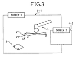
- FIG. 3 shows the screen 4 of an arrangement (initial arrangement) in accordance with a work cell determined by one of these methods.
- the display 18 is assumed to be one which can simultaneously arrange and display the "screen 1" 4-1 and the "screen 2" 4-2 on a single screen 4.
- the "screen 2" 4-2 is the special screen for "display of image captured by image capturing means 2"
- the general display including the display such as in FIG. 3 is given by the "screen 1" 4-1.
- reference numerals 1, 2, and 3 indicate, in order, the robot, image capturing means of the visual sensor (mounted on the robot), and workpiece.
- reference numeral 21 indicates the center point of the camera defined by the image capturing means 2
- reference symbol A indicates the direction of the optical axis passing through the center point of the camera (centerline of visual field) by a broken arrow.
- Step S2 the three-dimensional shape (visual volume) of the visual field of the image capturing means 2 is defined.
- the data of the height h0, depth d, and length 1 is input from for example the keyboard 16.
- h0 is made the optimal image capture distance of the image capturing means (actual) 2 considered to be actually used
- d and 1 the data of the specifications of the model in question or the data obtained by simple arithmetic from the same is employed. That is, normally, specifications describe sufficient data required for specifying the three-dimensional shape of the visual field in some form or another, so this may be used.
- the screen 1 (4-1) When inputting the data of the height h0, the depth d, and the length 1 , the screen 1 (4-1) displays a visual volume model 30 showing the visual volume such as shown in FIG. 4 .
- the camera center point 22 of the camera (image capturing means) in the visual field model is a point corresponding to the peak of the visual volume of the square pyramid (31), while the symbol B shows the direction of the visual field center line passing through the camera center point 22.
- the point on the visual field center line B down from the camera center point by exactly h0 is defined as the "view point" (23).
- the position of the view point 23 is unambiguously determined and can be simply calculated at any time if the camera center point 22 and visual field center line B are determined.
- Step S3 The three-dimensional model 30 defined at step S2 is joined with (attached to) the image capturing means in the work cell (the image capturing means 2 in the screen of FIG. 3 ). This is done to make the camera center point 22 of the visual field model match with the camera center point (camera center point of camera model) shown by reference numeral 21 in FIG. 3 and make the visual field center line B of the visual field model match with the visual field center line A shown by reference symbol A in FIG. 3 .
- the orientation of the visual volume around the visual field center line B is set so as to be aligned with the orientation of the image capturing means 2 in the visual field model shown in FIG. 4 .
- the calculations for this are performed in the simulation apparatus (10). Further, the image incorporating the joined results is displayed in the "screen 1" as shown in FIG. 5A (however, the detection reference point expressed by reference numeral 24 is displayed at the next step S4).
- the display of the visual field of the image capturing means by a three-dimensional shape in this way, the range which the visual sensor can detect can be directly grasped. Further, as illustrated in the figures, the relationship between the positions and orientations of the workpiece 3 and visual field can be easily grasped.
- Step S4 The tool coordinate system of the robot 1 is defined.
- the tool coordinate system is defined so that the origin of the tool coordinate system (tool tip point) matches with the above-mentioned view point 23.
- the directions of the X-axis (Xt1) and Y-axis (Ytl) of the tool coordinate system are set to match with the direction of the depth d and the direction of the length of the visual field for example, where the direction of the Z-axis (Zt1) of the tool coordinate system is set to match with the direction of the visual field center line A.
- the calculations for these are performed in the simulation apparatus 10.
- the thus defined tool coordinate system (coordinate system having tool tip point as origin) is actively used in the later-mentioned "graphic jog".
- Step S5 The detection reference point relating to the workpiece 3 is set.
- This detection reference point is the "point" utilized in the later-mentioned “graphic jog”. Further, in general, it designates the "point” representing the workpiece 3 as the object for capture and for example the "point” corresponding to the most important image capture location in the actual work.
- the point is designated by defining the coordinate system such as shown in FIG. 5B (hereinafter referred to as the "detection reference coordinate system"). For this, first, for example the mouse 16 is used to point to the origin 24 of the coordinate system on the image 4 shown in FIG. 5A (however, the detection reference point 24 not yet being displayed).
- the directions of the X-axis (Xdt) and the Y-axis (Ytl) of the detection reference coordinate system and the directions of the X-axis and Y-axis of the coordinate system defined in the simulation space are assumed to match.
- the origin (detection reference point) 24 is displayed in the image of FIG. 5A .
- the coordinate system such as shown in FIGS. 5B and 5C by graphics.
- step S1 to step S5 the "Preparations 1" are completed.
- similar preparations to the above are performed for each robot in accordance with need.
- data able to be used in common among the plurality of robots for example, data of the visual volume
- the applications content of work performed by robot system.
- FIG. 6 is a flow chart setting the routine relating to the graphic jog. The principal points of each step are as follows:
- Step T1 The robot 1 for performing the graphic jog is designated. As shown in FIG. 3 , when there is a single robot (mounting an image capturing means) (robot 1), this is designated. When there are a plurality of robots present in the defined work cell, one among these is designated on the display screen 4 by the mouse 16 etc.
- Step T2 The detection reference point made the target of movement of the graphic jog is designated. As shown in FIG. 5A , when there is a single detection reference point (detection reference point 24), this is designated. When there are a plurality of detection reference points present in a defined work cell, one among these is designated on the display screen 4 using the mouse 16 etc.
- Step T3 The graphic jog processing is performed. This moves the robot 1 in the simulation space on the screen 1 (4-1).
- the target point is made the detection reference point defined at step S2.
- the robot 1 is made to move so as to make the tool tip point 23 set at step S4 match with the detection reference point 24.
- the robot 1 is made to move so as to make the tool coordinate system (see FIG. 5C ) of the robot 1 match with the detection reference coordinate system (see FIG. 5B ).
- the state of this robot movement is displayed in an animation form on the screen 1 (4-1).
- the image capturing means 2 also moves together with the robot 1 and the visual volume model 30 attached to the image capturing means 2 at step S3 also similarly moves.
- the screen 1 in FIG. 7 displays the display image a little before the movement of this graphic job is ended.
- the tool tip point (that is, the view point of the image capturing means 2) 23 reaches near the detection reference point 24, but does not yet match with it. In the state where the movement of the graphic jog ends, the tool tip point 23 matches with the detection reference point 24.
- the tool tip point 23 and the detection reference point 24 are the origins of the tool coordinate system and detection reference coordinate system (see FIG. 5C and FIG. 5B ).
- the above two coordinate systems also match in orientation. That is, Xtl axis and Xdt axis, the Ytl axis and Ydt axis, and the Ztl axis and Zdt axis all face the same directions, respectively. While the illustration is omitted in FIG. 7 , the states of match of the orientations of the coordinate systems may also be displayed overlaid.
- the graphic jog explained above is useful for studying the orientation of the robot 1. For example, by checking if the orientation of the robot is unreasonable or if there is a possibility of interference with surrounding objects at the time of making the tool tip point 23 set to the view point of the image capturing means 2 match with the detection reference point 24, it is possible to evaluate the suitability of the position and orientation of arrangement of the robot which the work cell sets. If there is a problem in the position or orientation of arrangement of the robot (for example if the workpiece 3 and the robot 1 are too far apart or if the direction of the robot base is unsuitable), the position and orientation of arrangement of the robot in the work cell are corrected or the position and orientation of the workpiece or the position and orientation of mounting of the image capturing means are changed so as to correct the work cell. These corrections are performed until the orientation of detection of the robot 1 to the detection reference point 24 simulated by the graphic jog becomes suitable. Therefore, if necessary, the processings of "Preparations 1" and "graphic jog" are repeated.
- step S1 the "display of image visible from image capturing means 2" by the screen 2 (4-2) will be explained.
- the relationship between the position and orientation of the visual volume model 30 having the camera center point 21 (and 22) as the peak in the simulation space and the position and orientation of the robot 1 is set and the position and orientation of the workpiece 3 etc. are also known as data of the work cell. Therefore, if giving the data of the position and orientation of the robot 1, it is possible to find by calculation the image visible from the image capturing means 2 from the three-dimensional position data grasped in the visual field according to the visual volume model 30. This calculation can for example be image projection calculation by applying the model of a pinhole camera to the image capturing means 2. Note that the software itself for simulating this kind of image projection of an image capturing means is known. A detailed explanation will be omitted.
- the display of the screen 2 (4-2) may be performed at any time, but here if assuming display at the time of execution of the graphic jog, for example the display image such as shown in the screen 2 in FIG. 7 is obtained (in FIG. 3 and FIG. 5A , the screen 2 is not shown).
- the state where the tool tip point (that is, the view point of the image capturing means 2) 23 is near the detection reference point 24 corresponding to the screen displayed on the screen 1 (4-1) is displayed.
- the state where the movement of the graphic jog is ended naturally the state where the tool tip point 23 matches with the detection reference point 24 is displayed.
- Step U1 The arrangement of the work cell provided through the above process is displayed on the screen 1.
- the image displayed on the screen 1 is for example one as shown in FIG. 5A .
- This display includes the images of the robot 1, image capturing means 2, workpiece 3, and visual volume model 30. If using the above graphic jog to correct the work cell, the arrangement after that correction is displayed.
- Step U2 The program for the operation simulation is designated.
- the list of programs is shown divided in the screen 1 (4-1) and one among them is designated by the mouse 16.
- the one robot operation program including the robot movement commands and the commands for correcting the path of movement using the visual sensor relating to the robot movement commands (hereinafter referred to as the "correction commands using the visual sensor") is designated.
- Step U3 The correction amount for the path of movement of the robot corresponding to the correction command using the visual sensor is set (hereinafter simply referred to as the "setting of correction amount").
- the correction amount ⁇ Q2 ( ⁇ X2, ⁇ Y2, ⁇ Z2; ⁇ P2, ⁇ W2, ⁇ R2) for changing the position of the teaching point Q2 to Q2' (X2+ ⁇ X2, Y2+ ⁇ Y2, Z2+ ⁇ Z2; P2+ ⁇ P2, W2+ ⁇ W2, R2+ ⁇ R2) is set for the linear movement from the teaching point Q1 (X1, Y1, Z1; P1, W1, R1) to the teaching point Q2 (X2, Y2, Z2; P2, W2, R2).
- the movement from Q1 to Q2 (after correction Q1 to Q2') is used in the yes side output of step V6 to step 10 in the flow chart of the simulation explained next (see FIG. 10B ).
- Step V1 The screen 1 (4-1) is made to display an image with the visual volume model 30 off as illustrated in FIG. 11 .
- Step V2 The number N of lines of the operation program designated is read.
- Step V3 The operation program is started up.
- Step V4 The line number index I is initialized to "1".
- Step V5 The first line of the operation program is read.
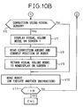
- Step V6 It is judged if the read line is a correction command using the visual sensor (further provided with an image capturing command including a detection command for the visual sensor for correcting the path of movement of the robot). If the result is yes, the routine proceeds to step V7. If no, it proceeds to step V10.
- Step V7 The display of the screen 1 is switched to the image displaying the visual volume model 30 such as shown in FIG. 12 . Due to this, an operator can obtain a visual grasp of the fact that a correction command using the visual sensor has been output.
- Step V8 The set correction amount is read and the position of movement of the robot 1 is corrected.
- the position of movement initially designated is the above-mentioned teaching point Q2 and that position is changed to Q2'. That is, the correction amount ⁇ Q2 ( ⁇ X2, ⁇ Y2, ⁇ Z2; ⁇ P2, ⁇ W2, ⁇ R2) is read out and Q2 (X2, Y2, Z2; P2, W2, R2) is changed to Q2' (X2+ ⁇ X2, Y2+ ⁇ Y2, Z2+ ⁇ Z2; P2+ ⁇ P2, W2+ ⁇ W2, R2+ ⁇ R2).
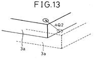
- the position and orientation of display of the workpiece 3 in the screen 1 (4-1) can be changed by exactly the corresponding correction amount ⁇ Q2 as shown in FIG. 13 . Further, if there is a workpiece jig or other separate surrounding object, the position and orientation of the display can be changed together.
- Step V9 The visual volume model 30 in the screen 1 (4-1) is returned to the nondisplayed state.
- Step V10 The robot 1 is made to move in the simulation space.
- the robot 1 is moved from Q1 (X1, Y1, Z1; P1, W1, R1) to Q2' (X2+ ⁇ X2, Y2+ ⁇ Y2, Z2+ ⁇ Z2; P2+ ⁇ P2, W2+ ⁇ W2, R2+ ⁇ R2).
- This state is displayed on the screen 1 in the form of an animation.
- step V6 directly to step V10 (when there is no correction command using the visual sensor)
- the command of that line is executed in the usual manner.
- Step V11 Whether the line is the final line is judged. If the result is yes, the processing is ended. If no, the routine proceeds to step V12.
- Step V12 The line index I is incremented by "1" and the routine returns to step V5.
Landscapes
- Engineering & Computer Science (AREA)
- Human Computer Interaction (AREA)
- Manufacturing & Machinery (AREA)
- Physics & Mathematics (AREA)
- General Physics & Mathematics (AREA)
- Automation & Control Theory (AREA)
- Robotics (AREA)
- Mechanical Engineering (AREA)
- Numerical Control (AREA)
- Manipulator (AREA)
- Management, Administration, Business Operations System, And Electronic Commerce (AREA)
Claims (7)
- Eine Simulationsvorrichtung zum Einrichten und zum gleichzeitigen Anzeigen auf einem Bildschirm (4) von dreidimensionalen Modellen zumindest eines Roboters (1), eines Werkstücks (3), und eines Bildaufnahmemittels (2) eines visuellen Sensors und zum Simulieren des Arbeitsablaufs des Roboters (1),
dadurch gekennzeichnet, dass
ein Blickfeldanzeigemittel (41) zum Anzeigen des Blickfelds des Bildaufnahmemittels (2) auf dem Bildschirm (4) mittels einer dreidimensionalen Form (30) vorgesehen ist,
ein Simulationsmittel (45) zum Ausführen einer die Roboterbewegungen umfassenden Simulation gemäß eines Roboterarbeitsablaufprogramms, das Bildaufnahmebefehle, die das Bildaufnahmemittel (2) veranlassen, ein Bild aufzunehmen, Bewegungsbefehle, die den Roboter (1) veranlassen, sich entlang eines Pfades zu bewegen, und auf die Bildaufnahmebefehle und die Bewegungsbefehle bezogene Korrekturbefehle umfasst, und
ein Anzeigeumschaltmittel (47) zum Umschalten eines Anzeigemodus der Anzeige der dreidimensionalen Form (30) des Blickfelds gemäß dem Bildaufnahmebefehl, wobei das Umschalten des Anzeigemodus ein Umschalten zwischen Anzeige/Nichtanzeige gemäß dem Bildaufnahmebefehl ist, sodass ein Anwender die dreidimensionale Form des Blickfelds und einen Zeitsteuerung der Ausgabe des Bildaufnahmebefehls visuell bestätigen kann. - Eine Simulationsvorrichtung nach Anspruch 1, dadurch gekennzeichnet, dass die dreidimensionale Form (30) des Blickfelds eine quadratische Pyramide (31) ist.
- Eine Simulationsvorrichtung nach einem der Ansprüche 1 oder 2, dadurch gekennzeichnet, dass diese ferner mit einem Bildanzeigemittel (42) zur Anzeige eines durch das Bildaufnahmemittel (2) in dem Blickfeld aufgenommenen Bildes auf einem Bildschirm (4) ausgestattet ist.
- Eine Simulationsvorrichtung nach einem der Ansprüche 1 bis 3, dadurch gekennzeichnet, dass das Bildaufnahmemittel (2) an dem Roboter (1) befestigt ist.
- Eine Simulationsvorrichtung nach Anspruch 4, dadurch gekennzeichnet, dass diese ferner ausgestattet ist mit:einem Referenzpunktkennzeichnungsmittel (43) zum Kennzeichnen eines ersten auf das Werkstück (3) bezogenen Referenzpunktes (24) auf dem Bildschirm (4) undeinem Roboterarbeitsablaufmittel (44), das den Roboter (1) auf dem Bildschirm (4) veranlasst, einen Arbeitsablauf abzuarbeiten, sodass ein auf das Blickfeld bezogener, vorherbestimmter zweiter Referenzpunkt (23) mit dem ersten Referenzpunkt (24) übereinstimmt.
- Eine Simulationsvorrichtung nach einem der Ansprüche 1 bis 5, dadurch gekennzeichnet, dass es ferner ausgestattet ist mit:Speichermitteln (12, 13, 14), zum Speichern von auf den - durch die Bewegungsbefehle gekennzeichneten - Bewegungspfad bezogener Korrekturwerte, undPfadkorrekturmittel (46), um die gespeicherten Korrekturwerte auszulesen und um den Bewegungspfad auf dem Bildschirm während der Simulation durch die Korrekturbefehle zu korrigieren.
- Simulationsvorrichtung nach Anspruch 6, zum Korrigieren der Position der Anordnung zumindest eines Werkstücks und Peripheriegerätes auf dem Bildschirm gemäß der Korrekturwerte.
Applications Claiming Priority (2)
| Application Number | Priority Date | Filing Date | Title |
|---|---|---|---|
| JP2003372518A JP3732494B2 (ja) | 2003-10-31 | 2003-10-31 | シミュレーション装置 |
| JP2003372518 | 2003-10-31 |
Publications (3)
| Publication Number | Publication Date |
|---|---|
| EP1527850A2 EP1527850A2 (de) | 2005-05-04 |
| EP1527850A3 EP1527850A3 (de) | 2009-12-30 |
| EP1527850B1 true EP1527850B1 (de) | 2012-08-15 |
Family
ID=34420237
Family Applications (1)
| Application Number | Title | Priority Date | Filing Date |
|---|---|---|---|
| EP04025427A Expired - Lifetime EP1527850B1 (de) | 2003-10-31 | 2004-10-26 | Simulationsvorrichtung |
Country Status (3)
| Country | Link |
|---|---|
| US (1) | US7447615B2 (de) |
| EP (1) | EP1527850B1 (de) |
| JP (1) | JP3732494B2 (de) |
Cited By (1)
| Publication number | Priority date | Publication date | Assignee | Title |
|---|---|---|---|---|
| CN104070524A (zh) * | 2013-03-25 | 2014-10-01 | 精工爱普生株式会社 | 机器人系统以及图像显示装置 |
Families Citing this family (51)
| Publication number | Priority date | Publication date | Assignee | Title |
|---|---|---|---|---|
| US8944070B2 (en) | 1999-04-07 | 2015-02-03 | Intuitive Surgical Operations, Inc. | Non-force reflecting method for providing tool force information to a user of a telesurgical system |
| US9789608B2 (en) | 2006-06-29 | 2017-10-17 | Intuitive Surgical Operations, Inc. | Synthetic representation of a surgical robot |
| JP3946753B2 (ja) * | 2005-07-25 | 2007-07-18 | ファナック株式会社 | ロボットプログラム評価・修正方法及びロボットプログラム評価・修正装置 |
| DE102005048136B4 (de) | 2005-10-06 | 2010-01-21 | Kuka Roboter Gmbh | Verfahren zum Bestimmen eines virtuellen Tool-Center-Points |
| JP4153528B2 (ja) * | 2006-03-10 | 2008-09-24 | ファナック株式会社 | ロボットシミュレーションのための装置、プログラム、記録媒体及び方法 |
| DE102006022483A1 (de) * | 2006-05-13 | 2007-11-29 | Kuka Roboter Gmbh | Verfahren und Vorrichtung zum Anzeigen einer Roboterbahn zur Unterstützung einer Ortsänderung eines Stützpunktes |
| JP4238256B2 (ja) | 2006-06-06 | 2009-03-18 | ファナック株式会社 | ロボットシミュレーション装置 |
| JP2007334678A (ja) * | 2006-06-15 | 2007-12-27 | Fanuc Ltd | ロボットシミュレーション装置 |
| US10258425B2 (en) | 2008-06-27 | 2019-04-16 | Intuitive Surgical Operations, Inc. | Medical robotic system providing an auxiliary view of articulatable instruments extending out of a distal end of an entry guide |
| US20090192523A1 (en) | 2006-06-29 | 2009-07-30 | Intuitive Surgical, Inc. | Synthetic representation of a surgical instrument |
| US9718190B2 (en) | 2006-06-29 | 2017-08-01 | Intuitive Surgical Operations, Inc. | Tool position and identification indicator displayed in a boundary area of a computer display screen |
| US12357400B2 (en) | 2006-06-29 | 2025-07-15 | Intuitive Surgical Operations, Inc. | Synthetic representation of a surgical robot |
| US10008017B2 (en) | 2006-06-29 | 2018-06-26 | Intuitive Surgical Operations, Inc. | Rendering tool information as graphic overlays on displayed images of tools |
| JP2008021092A (ja) | 2006-07-12 | 2008-01-31 | Fanuc Ltd | ロボットシステムのシミュレーション装置 |
| KR100738052B1 (ko) * | 2006-12-26 | 2007-07-12 | 주식회사 이디 | 지능형 로봇 제어 시뮬레이션 시스템 |
| JP4298757B2 (ja) * | 2007-02-05 | 2009-07-22 | ファナック株式会社 | ロボット機構のキャリブレーション装置及び方法 |
| JP2008296330A (ja) * | 2007-05-31 | 2008-12-11 | Fanuc Ltd | ロボットシミュレーション装置 |
| US9089256B2 (en) | 2008-06-27 | 2015-07-28 | Intuitive Surgical Operations, Inc. | Medical robotic system providing an auxiliary view including range of motion limitations for articulatable instruments extending out of a distal end of an entry guide |
| US9084623B2 (en) | 2009-08-15 | 2015-07-21 | Intuitive Surgical Operations, Inc. | Controller assisted reconfiguration of an articulated instrument during movement into and out of an entry guide |
| US9469034B2 (en) | 2007-06-13 | 2016-10-18 | Intuitive Surgical Operations, Inc. | Method and system for switching modes of a robotic system |
| US8620473B2 (en) | 2007-06-13 | 2013-12-31 | Intuitive Surgical Operations, Inc. | Medical robotic system with coupled control modes |
| JP5038795B2 (ja) * | 2007-07-02 | 2012-10-03 | 株式会社日立製作所 | 作業指示装置、作業指示方法、作業指示プログラム及び作業指示記憶媒体 |
| DE102007055205A1 (de) * | 2007-11-19 | 2009-05-20 | Kuka Roboter Gmbh | Verfahren zum Ermitteln eines Aufstellortes und zum Aufstellen einer Erfassungsvorrichtung eines Navigationssystems |
| JP4347386B2 (ja) * | 2008-01-23 | 2009-10-21 | ファナック株式会社 | 加工用ロボットプラグラムの作成装置 |
| ATE452005T1 (de) * | 2008-02-13 | 2010-01-15 | Abb As | System und verfahren zur visualisierung von verfahrensfehlern |
| US12239396B2 (en) | 2008-06-27 | 2025-03-04 | Intuitive Surgical Operations, Inc. | Medical robotic system providing an auxiliary view including range of motion limitations for articulatable instruments extending out of a distal end of an entry guide |
| JP5722527B2 (ja) * | 2009-03-19 | 2015-05-20 | 株式会社デンソーウェーブ | 視覚検査装置の評価システム |
| US12266040B2 (en) | 2009-03-31 | 2025-04-01 | Intuitive Surgical Operations, Inc. | Rendering tool information as graphic overlays on displayed images of tools |
| DE102009034244A1 (de) * | 2009-07-22 | 2011-01-27 | Kuka Roboter Gmbh | Verfahren und Vorrichtung zur Vermessung eines Bauteils |
| US9492927B2 (en) | 2009-08-15 | 2016-11-15 | Intuitive Surgical Operations, Inc. | Application of force feedback on an input device to urge its operator to command an articulated instrument to a preferred pose |
| US8918211B2 (en) | 2010-02-12 | 2014-12-23 | Intuitive Surgical Operations, Inc. | Medical robotic system providing sensory feedback indicating a difference between a commanded state and a preferred pose of an articulated instrument |
| US8321055B2 (en) * | 2009-11-03 | 2012-11-27 | Jadak, Llc | System and method for multiple view machine vision target location |
| US20120290130A1 (en) * | 2011-05-10 | 2012-11-15 | Agile Planet, Inc. | Method to Model and Program a Robotic Workcell |
| JP5838873B2 (ja) * | 2012-03-15 | 2016-01-06 | オムロン株式会社 | シミュレーション装置、シミュレーション方法、および、シミュレーションプログラム |
| US9753453B2 (en) * | 2012-07-09 | 2017-09-05 | Deep Learning Robotics Ltd. | Natural machine interface system |
| JP5670416B2 (ja) | 2012-12-28 | 2015-02-18 | ファナック株式会社 | ロボットシステム表示装置 |
| US10507066B2 (en) | 2013-02-15 | 2019-12-17 | Intuitive Surgical Operations, Inc. | Providing information of tools by filtering image areas adjacent to or on displayed images of the tools |
| JP2014186588A (ja) * | 2013-03-25 | 2014-10-02 | Seiko Epson Corp | シミュレーション装置、プログラム及び画像生成方法 |
| WO2015079740A1 (ja) * | 2013-11-28 | 2015-06-04 | 三菱電機株式会社 | ロボットシステムおよびロボットシステムの制御方法 |
| JP5850958B2 (ja) * | 2014-01-24 | 2016-02-03 | ファナック株式会社 | ワークを撮像するためのロボットプログラムを作成するロボットプログラミング装置 |
| JP5877857B2 (ja) * | 2014-03-10 | 2016-03-08 | ファナック株式会社 | ワークの取出工程をシミュレーションするロボットシミュレーション装置 |
| US9283678B2 (en) * | 2014-07-16 | 2016-03-15 | Google Inc. | Virtual safety cages for robotic devices |
| DE102014226899A1 (de) * | 2014-12-23 | 2016-06-23 | Siemens Healthcare Gmbh | Verfahren zum Betreiben eines medizinisch-robotischen Geräts und ein medizinisch-robotisches Gerät |
| WO2017198299A1 (en) * | 2016-05-19 | 2017-11-23 | Abb Schweiz Ag | Method of simulating a robotic system |
| JP6392817B2 (ja) * | 2016-08-04 | 2018-09-19 | ファナック株式会社 | シミュレーション装置 |
| DE112016007339T5 (de) * | 2016-10-14 | 2019-07-04 | Mitsubishi Electric Corporation | Simulationsvorrichtung |
| JP6450727B2 (ja) * | 2016-10-28 | 2019-01-09 | ファナック株式会社 | ロボットが行う物品整列作業のシミュレーションのための装置、方法、プログラム及び記録媒体 |
| JP2019093529A (ja) * | 2017-11-27 | 2019-06-20 | アズビル株式会社 | ポインタ装置 |
| US10676022B2 (en) | 2017-12-27 | 2020-06-09 | X Development Llc | Visually indicating vehicle caution regions |
| JP6898374B2 (ja) * | 2019-03-25 | 2021-07-07 | ファナック株式会社 | ロボット装置の動作を調整する動作調整装置およびロボット装置の動作を調整する動作調整方法 |
| WO2023007621A1 (ja) * | 2021-07-28 | 2023-02-02 | ファナック株式会社 | シミュレーション装置 |
Family Cites Families (9)
| Publication number | Priority date | Publication date | Assignee | Title |
|---|---|---|---|---|
| US4754415A (en) * | 1984-10-12 | 1988-06-28 | Diffracto Ltd. | Robotic alignment and part simulation |
| US4831549A (en) * | 1987-07-28 | 1989-05-16 | Brigham Young University | Device and method for correction of robot inaccuracy |
| US5729471A (en) * | 1995-03-31 | 1998-03-17 | The Regents Of The University Of California | Machine dynamic selection of one video camera/image of a scene from multiple video cameras/images of the scene in accordance with a particular perspective on the scene, an object in the scene, or an event in the scene |
| US5943476A (en) * | 1996-06-13 | 1999-08-24 | August Design, Inc. | Method and apparatus for remotely sensing orientation and position of objects |
| US6122003A (en) * | 1997-08-22 | 2000-09-19 | Flashpoint Technology, Inc. | Method and apparatus for changing operating modes of an image capture device |
| US6249285B1 (en) * | 1998-04-06 | 2001-06-19 | Synapix, Inc. | Computer assisted mark-up and parameterization for scene analysis |
| US6161051A (en) * | 1998-05-08 | 2000-12-12 | Rockwell Technologies, Llc | System, method and article of manufacture for utilizing external models for enterprise wide control |
| US7092860B1 (en) * | 1999-02-03 | 2006-08-15 | Mitutoyo Corporation | Hardware simulation systems and methods for vision inspection systems |
| JP2003150219A (ja) * | 2001-11-12 | 2003-05-23 | Fanuc Ltd | 作業機械のシミュレーション装置 |
-
2003
- 2003-10-31 JP JP2003372518A patent/JP3732494B2/ja not_active Expired - Fee Related
-
2004
- 2004-10-26 EP EP04025427A patent/EP1527850B1/de not_active Expired - Lifetime
- 2004-10-26 US US10/972,675 patent/US7447615B2/en not_active Expired - Lifetime
Cited By (2)
| Publication number | Priority date | Publication date | Assignee | Title |
|---|---|---|---|---|
| CN104070524A (zh) * | 2013-03-25 | 2014-10-01 | 精工爱普生株式会社 | 机器人系统以及图像显示装置 |
| CN104070524B (zh) * | 2013-03-25 | 2018-11-09 | 精工爱普生株式会社 | 机器人系统以及图像显示装置 |
Also Published As
| Publication number | Publication date |
|---|---|
| US7447615B2 (en) | 2008-11-04 |
| EP1527850A3 (de) | 2009-12-30 |
| EP1527850A2 (de) | 2005-05-04 |
| JP3732494B2 (ja) | 2006-01-05 |
| JP2005135278A (ja) | 2005-05-26 |
| US20050096892A1 (en) | 2005-05-05 |
Similar Documents
| Publication | Publication Date | Title |
|---|---|---|
| EP1527850B1 (de) | Simulationsvorrichtung | |
| JP3537362B2 (ja) | ロボットシステム用グラフィック表示装置 | |
| US7512459B2 (en) | Robot off-line simulation apparatus | |
| CN100537156C (zh) | 机器人的离线示教装置 | |
| US6587752B1 (en) | Robot operation teaching method and apparatus | |
| EP1936458B1 (de) | Vorrichtung, Verfahren, Programm und Aufzeichnungsmedium zur Offlineprogrammierung von Robotern | |
| EP1842631B1 (de) | Vorrichtung und Verfahren zur Bahnerzeugung für einen Industrieroboter | |
| JP3673749B2 (ja) | シミュレーション装置 | |
| JP5113666B2 (ja) | ロボット教示システム及びロボットの動作のシミュレーション結果の表示方法 | |
| JP4171488B2 (ja) | オフラインプログラミング装置 | |
| JP6825026B2 (ja) | 情報処理装置、情報処理方法及びロボットシステム | |
| CN102744727A (zh) | 预测机器人的着眼部位与周边物的干涉的方法及装置 | |
| US5341458A (en) | Method of and system for generating teaching data for robots | |
| CN112958974A (zh) | 一种基于三维视觉的可交互自动化焊接系统 | |
| JP2021059012A (ja) | 情報処理装置、情報処理方法及びロボットシステム | |
| CN100404211C (zh) | 用于多关节型机器人的教导数据准备方法 | |
| JP5291482B2 (ja) | ロボット教示プログラム修正装置 | |
| JPH10124130A (ja) | 組立装置 | |
| JPS6097409A (ja) | ロボツトの動作教示法 | |
| US20170269574A1 (en) | Robot control device that controls robot to perform machining operation, and robot program generator | |
| JP7701465B2 (ja) | 作業支援装置及び作業支援方法 | |
| US20220226982A1 (en) | Method Of Creating Control Program For Robot, System Executing Processing Of Creating Control Program For Robot, And Non-Transitory Computer-Readable Storage Medium | |
| JPS63273912A (ja) | 産業用ロボットのティ−チングデ−タ作成方式 | |
| JP2000207005A (ja) | 数値制御デ―タ生成装置および数値制御デ―タ生成方法 | |
| JPS63273907A (ja) | 産業用ロボットのティ−チングデ−タ作成システム |
Legal Events
| Date | Code | Title | Description |
|---|---|---|---|
| PUAI | Public reference made under article 153(3) epc to a published international application that has entered the european phase |
Free format text: ORIGINAL CODE: 0009012 |
|
| AK | Designated contracting states |
Kind code of ref document: A2 Designated state(s): AT BE BG CH CY CZ DE DK EE ES FI FR GB GR HU IE IT LI LU MC NL PL PT RO SE SI SK TR |
|
| AX | Request for extension of the european patent |
Extension state: AL HR LT LV MK |
|
| PUAL | Search report despatched |
Free format text: ORIGINAL CODE: 0009013 |
|
| AK | Designated contracting states |
Kind code of ref document: A3 Designated state(s): AT BE BG CH CY CZ DE DK EE ES FI FR GB GR HU IE IT LI LU MC NL PL PT RO SE SI SK TR |
|
| AX | Request for extension of the european patent |
Extension state: AL HR LT LV MK |
|
| RIC1 | Information provided on ipc code assigned before grant |
Ipc: G05B 19/4069 20060101ALI20091124BHEP Ipc: B25J 9/16 20060101AFI20050203BHEP |
|
| 17P | Request for examination filed |
Effective date: 20100107 |
|
| 17Q | First examination report despatched |
Effective date: 20100809 |
|
| AKX | Designation fees paid |
Designated state(s): DE |
|
| RAP1 | Party data changed (applicant data changed or rights of an application transferred) |
Owner name: FANUC CORPORATION |
|
| GRAP | Despatch of communication of intention to grant a patent |
Free format text: ORIGINAL CODE: EPIDOSNIGR1 |
|
| RIN1 | Information on inventor provided before grant (corrected) |
Inventor name: NAGATSUKA, YOSHIHARU Inventor name: WATANABE, ATSUSHI |
|
| GRAS | Grant fee paid |
Free format text: ORIGINAL CODE: EPIDOSNIGR3 |
|
| GRAA | (expected) grant |
Free format text: ORIGINAL CODE: 0009210 |
|
| AK | Designated contracting states |
Kind code of ref document: B1 Designated state(s): DE |
|
| REG | Reference to a national code |
Ref country code: DE Ref legal event code: R096 Ref document number: 602004038888 Country of ref document: DE Effective date: 20121011 |
|
| PLBE | No opposition filed within time limit |
Free format text: ORIGINAL CODE: 0009261 |
|
| STAA | Information on the status of an ep patent application or granted ep patent |
Free format text: STATUS: NO OPPOSITION FILED WITHIN TIME LIMIT |
|
| 26N | No opposition filed |
Effective date: 20130516 |
|
| REG | Reference to a national code |
Ref country code: DE Ref legal event code: R097 Ref document number: 602004038888 Country of ref document: DE Effective date: 20130516 |
|
| PGFP | Annual fee paid to national office [announced via postgrant information from national office to epo] |
Ref country code: DE Payment date: 20230830 Year of fee payment: 20 |
|
| REG | Reference to a national code |
Ref country code: DE Ref legal event code: R071 Ref document number: 602004038888 Country of ref document: DE |