EP2153102B1 - Rohrkopplung mit beweglichen greifelementen - Google Patents
Rohrkopplung mit beweglichen greifelementen Download PDFInfo
- Publication number
- EP2153102B1 EP2153102B1 EP08755442A EP08755442A EP2153102B1 EP 2153102 B1 EP2153102 B1 EP 2153102B1 EP 08755442 A EP08755442 A EP 08755442A EP 08755442 A EP08755442 A EP 08755442A EP 2153102 B1 EP2153102 B1 EP 2153102B1
- Authority
- EP
- European Patent Office
- Prior art keywords
- segments
- coupling
- gripping
- pipe elements
- pipe
- Prior art date
- Legal status (The legal status is an assumption and is not a legal conclusion. Google has not performed a legal analysis and makes no representation as to the accuracy of the status listed.)
- Active
Links
Images


Classifications
-
- F—MECHANICAL ENGINEERING; LIGHTING; HEATING; WEAPONS; BLASTING
- F16—ENGINEERING ELEMENTS AND UNITS; GENERAL MEASURES FOR PRODUCING AND MAINTAINING EFFECTIVE FUNCTIONING OF MACHINES OR INSTALLATIONS; THERMAL INSULATION IN GENERAL
- F16L—PIPES; JOINTS OR FITTINGS FOR PIPES; SUPPORTS FOR PIPES, CABLES OR PROTECTIVE TUBING; MEANS FOR THERMAL INSULATION IN GENERAL
- F16L39/00—Joints or fittings for double-walled or multi-channel pipes or pipe assemblies
-
- F—MECHANICAL ENGINEERING; LIGHTING; HEATING; WEAPONS; BLASTING
- F16—ENGINEERING ELEMENTS AND UNITS; GENERAL MEASURES FOR PRODUCING AND MAINTAINING EFFECTIVE FUNCTIONING OF MACHINES OR INSTALLATIONS; THERMAL INSULATION IN GENERAL
- F16L—PIPES; JOINTS OR FITTINGS FOR PIPES; SUPPORTS FOR PIPES, CABLES OR PROTECTIVE TUBING; MEANS FOR THERMAL INSULATION IN GENERAL
- F16L23/00—Flanged joints
- F16L23/04—Flanged joints the flanges being connected by members tensioned in the radial plane
- F16L23/08—Flanged joints the flanges being connected by members tensioned in the radial plane connection by tangentially arranged pin and nut
-
- F—MECHANICAL ENGINEERING; LIGHTING; HEATING; WEAPONS; BLASTING
- F16—ENGINEERING ELEMENTS AND UNITS; GENERAL MEASURES FOR PRODUCING AND MAINTAINING EFFECTIVE FUNCTIONING OF MACHINES OR INSTALLATIONS; THERMAL INSULATION IN GENERAL
- F16L—PIPES; JOINTS OR FITTINGS FOR PIPES; SUPPORTS FOR PIPES, CABLES OR PROTECTIVE TUBING; MEANS FOR THERMAL INSULATION IN GENERAL
- F16L17/00—Joints with packing adapted to sealing by fluid pressure
- F16L17/02—Joints with packing adapted to sealing by fluid pressure with sealing rings arranged between outer surface of pipe and inner surface of sleeve or socket
- F16L17/04—Joints with packing adapted to sealing by fluid pressure with sealing rings arranged between outer surface of pipe and inner surface of sleeve or socket with longitudinally split or divided sleeve
-
- F—MECHANICAL ENGINEERING; LIGHTING; HEATING; WEAPONS; BLASTING
- F16—ENGINEERING ELEMENTS AND UNITS; GENERAL MEASURES FOR PRODUCING AND MAINTAINING EFFECTIVE FUNCTIONING OF MACHINES OR INSTALLATIONS; THERMAL INSULATION IN GENERAL
- F16L—PIPES; JOINTS OR FITTINGS FOR PIPES; SUPPORTS FOR PIPES, CABLES OR PROTECTIVE TUBING; MEANS FOR THERMAL INSULATION IN GENERAL
- F16L21/00—Joints with sleeve or socket
- F16L21/06—Joints with sleeve or socket with a divided sleeve or ring clamping around the pipe ends
- F16L21/065—Joints with sleeve or socket with a divided sleeve or ring clamping around the pipe ends tightened by tangentially-arranged threaded pins
-
- F—MECHANICAL ENGINEERING; LIGHTING; HEATING; WEAPONS; BLASTING
- F16—ENGINEERING ELEMENTS AND UNITS; GENERAL MEASURES FOR PRODUCING AND MAINTAINING EFFECTIVE FUNCTIONING OF MACHINES OR INSTALLATIONS; THERMAL INSULATION IN GENERAL
- F16L—PIPES; JOINTS OR FITTINGS FOR PIPES; SUPPORTS FOR PIPES, CABLES OR PROTECTIVE TUBING; MEANS FOR THERMAL INSULATION IN GENERAL
- F16L21/00—Joints with sleeve or socket
- F16L21/08—Joints with sleeve or socket with additional locking means
-
- F—MECHANICAL ENGINEERING; LIGHTING; HEATING; WEAPONS; BLASTING
- F16—ENGINEERING ELEMENTS AND UNITS; GENERAL MEASURES FOR PRODUCING AND MAINTAINING EFFECTIVE FUNCTIONING OF MACHINES OR INSTALLATIONS; THERMAL INSULATION IN GENERAL
- F16L—PIPES; JOINTS OR FITTINGS FOR PIPES; SUPPORTS FOR PIPES, CABLES OR PROTECTIVE TUBING; MEANS FOR THERMAL INSULATION IN GENERAL
- F16L23/00—Flanged joints
- F16L23/16—Flanged joints characterised by the sealing means
- F16L23/18—Flanged joints characterised by the sealing means the sealing means being rings
-
- Y—GENERAL TAGGING OF NEW TECHNOLOGICAL DEVELOPMENTS; GENERAL TAGGING OF CROSS-SECTIONAL TECHNOLOGIES SPANNING OVER SEVERAL SECTIONS OF THE IPC; TECHNICAL SUBJECTS COVERED BY FORMER USPC CROSS-REFERENCE ART COLLECTIONS [XRACs] AND DIGESTS
- Y10—TECHNICAL SUBJECTS COVERED BY FORMER USPC
- Y10T—TECHNICAL SUBJECTS COVERED BY FORMER US CLASSIFICATION
- Y10T29/00—Metal working
- Y10T29/49—Method of mechanical manufacture
- Y10T29/49826—Assembling or joining
- Y10T29/49947—Assembling or joining by applying separate fastener
- Y10T29/49948—Multipart cooperating fastener [e.g., bolt and nut]
-
- Y—GENERAL TAGGING OF NEW TECHNOLOGICAL DEVELOPMENTS; GENERAL TAGGING OF CROSS-SECTIONAL TECHNOLOGIES SPANNING OVER SEVERAL SECTIONS OF THE IPC; TECHNICAL SUBJECTS COVERED BY FORMER USPC CROSS-REFERENCE ART COLLECTIONS [XRACs] AND DIGESTS
- Y10—TECHNICAL SUBJECTS COVERED BY FORMER USPC
- Y10T—TECHNICAL SUBJECTS COVERED BY FORMER US CLASSIFICATION
- Y10T29/00—Metal working
- Y10T29/49—Method of mechanical manufacture
- Y10T29/49826—Assembling or joining
- Y10T29/49947—Assembling or joining by applying separate fastener
- Y10T29/49963—Threaded fastener
-
- Y—GENERAL TAGGING OF NEW TECHNOLOGICAL DEVELOPMENTS; GENERAL TAGGING OF CROSS-SECTIONAL TECHNOLOGIES SPANNING OVER SEVERAL SECTIONS OF THE IPC; TECHNICAL SUBJECTS COVERED BY FORMER USPC CROSS-REFERENCE ART COLLECTIONS [XRACs] AND DIGESTS
- Y10—TECHNICAL SUBJECTS COVERED BY FORMER USPC
- Y10T—TECHNICAL SUBJECTS COVERED BY FORMER US CLASSIFICATION
- Y10T29/00—Metal working
- Y10T29/53—Means to assemble or disassemble
- Y10T29/53987—Tube, sleeve or ferrule
Definitions
- This invention relates to couplings for joining pipe elements in end-to-end relationship.
- U.S. Patent No. 7,086,131 discloses a coupling having a pair of coupling segments joined end-to-end by fasteners received in lugs at each end of the segments. A sealing member is positioned between the segments.
- the coupling is pre-assembled at the factory.
- the segments are designed and sized to receive pipe elements in the field which are inserted directly between the coupling segments in the pre-assembled state, without the need to disassemble and reassemble the coupling. After insertion of the pipe elements, the fasteners are tightened to effect a fluid-tight, mechanically restrained joint between the pipe elements.
- a pipe coupling of the kind defined by the preamble of claim 1 is known from the US 4 417 755 A .
- the invention concerns a pipe coupling of the kind defined by the features of claim 1.
- reaction surfaces are angularly oriented with respect to the projections. Orientation angles for the reaction surfaces from about 30° to about 60° are feasible, with 45° being preferred.
- the contact surfaces are also angularly oriented with respect to the projections. Orientation angles for the contact surfaces from about 30° to about 60° are feasible, with 45° being preferred.
- the contact surfaces project radially outwardly away from the central space.
- Each of the contact surfaces is engaged with one of the reaction surfaces of the segments.
- Each of the gripping bodies has end faces positioned opposite to one another.
- the segments have inwardly projecting shoulders positioned adjacent to the reaction surfaces.
- the shoulders are engageable with the end faces. Either the end faces or the shoulders or both are angularly oriented so as to cause rotation of the gripping bodies about an axis substantially perpendicular to the pipe elements when the coupling segments are drawn together. Adjustable tightening of the connection members draws the coupling segments together.
- the contact surfaces interact with the reaction surfaces to move the gripping bodies radially inwardly for engagement of the gripping surfaces with the pipe elements.
- the reaction surfaces extend in a tangential direction of the segments.
- the gripping bodies comprise a channel adapted to receive a sealing member. The channel is skewed relatively to the gripping surfaces so as to substantially align with the sealing member upon rotation of the gripping bodies.
- Another embodiment of the pipe coupling according to the invention comprises a plurality of segments connectable end-to- end.
- the segments surround a central space.
- Each segment has first and second arcuate grooves in spaced relation facing the central space.
- Connection members are positioned at opposite ends of each of the segments for adjustably connecting the segments to one another.
- the connection members are adjustably tightenable for drawing the segments toward one another.
- First and second reaction surfaces are positioned at opposite ends of each coupling segment in spaced relation to one another. The reaction surfaces face the central space.
- Each of the gripping bodies has first and second arcuate grooves positioned in spaced relation. The grooves face the central space.
- Each of the gripping bodies has a plurality of contact surfaces positioned in facing relation with the reaction surfaces. Each of the contact surfaces is engaged with one of the reaction surfaces on each of the segments.
- First and second retainers are received within the grooves of the couplings.
- Each of the retainers comprises an annular band having a plurality of teeth extending radially inwardly. Each annular band is split so as to permit radial motion of the teeth when the band is radially compressed. The first retainer is received within the first grooves in the coupling segments and the gripping bodies and the second retainer is received within the second grooves in the coupling segments and the gripping bodies.
- the teeth of the first retainer are angularly oriented toward the teeth of the second retainer, and the teeth of the second retainer are angularly oriented toward the teeth of the first retainer.
- Adjustable tightening of the connection members draws the coupling segments together.
- the contact surfaces interact with the reaction surfaces to move the gripping bodies radially inwardly for compressing the retainers into engagement with the pipe elements.
- the reaction surfaces extend in a tangential direction of the segments.
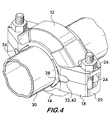
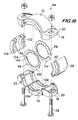
- FIG. 1 shows an exploded isometric view of a coupling embodiment 10 according to the invention.
- Coupling 10 comprises a plurality of segments 12 and 14. Segments 12 and 14 are connectable end-to-end to surround a central space 16. Connection of the segments is effected by connection members 18 positioned at opposite ends of each of the segments 12 and 14.
- the connection members comprise projections 20 which extend outwardly from the ends of the segments. Projections 20 have apertures 22 adapting them to receive fasteners, such as bolts 24 and nuts 26. The fasteners are adjustably tightenable and cooperate with the projections 20 for drawing the segments 12 and 14 toward the central space 16 upon tightening.
- Each segment has a pair of arcuate surfaces 28.
- Surfaces 28 are positioned in spaced relation to one another and face the central space 16.
- the arcuate surfaces engage and retain pipe elements 30 (see Figure 4 ) when the fasteners connecting projections 20 are tightened to draw the segments toward each other.
- the arcuate surfaces may engage circumferential grooves in the pipe elements, plain ended pipe elements, flared end pipe elements or pipe ends having a shoulder.
- Each segment also has at least one, but preferably a plurality of, reaction surfaces 32 positioned on the connection members 18.
- reaction surfaces 32 are positioned on each projection 20.
- the reaction surfaces are angularly oriented with respect to the projections, and may have an orientation angle 34 from about 30° to about 60° and are inclined so as to face the central space 16. Orientation angles of about 45° are preferred as explained below.
- Coupling 10 also comprises one or more gripping bodies.
- two gripping bodies 36 and 38 are positioned between the segments 12 and 14 opposite to one another.
- Each gripping body has a pair of gripping surfaces 40. Similar to the arcuate surfaces 28, the gripping surfaces are positioned in spaced apart relation and face the central space 16.
- Each gripping body has a pair of contact surfaces 42 positioned in facing relation with the reaction surfaces 32 on the projections 20 of the segments 12 and 14.
- the contact surfaces are also angularly oriented with respect to the projections, and may have an orientation angle 44 from about 30° to about 60°. Orientation angles of about 45° are preferred as explained below.
- the orientation angles 34 and 44 are complementary to one another, meaning that they have approximately the same angular orientation.
- a seal 46 is captured within the central space 16 by the segments 12 and 14 and the gripping bodies 36. Seal 46 ensures that the coupling 10 provides a fluid-tight joint between pipe ends.
- the seal 46 is sized so that, in an undeformed state, its outer circumference 48 supports the segments 12 and 14 and the gripping bodies 36 and 38 in spaced apart relation sufficient for pipe elements to be inserted into the central space 16 without disassembling the coupling.
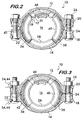
- Figure 2 shows the coupling 10 as received from the factory in the pre-assembled state, installation ready.
- the fasteners are not yet tightened, thereby allowing the segments 12 and 14 and the gripping bodies 36 and 38 to be positioned radially outwardly away from the central space 16 to allow pipe elements (not shown for clarity) to be inserted into the central space.
- the seal 46 is sized to hold the segments and gripping bodies radially outwardly to facilitate pipe insertion.
- the pipe elements engage the seal 46 which provides fluid tightness to the joint.
- the bolts 24 and nuts 26 are tightened, drawing the segments 12 and 14 toward one another and the central space 16.
- orientation angles of about 45° are preferred for both the reaction surfaces and the contact surfaces. The 45° angles ensure that, during the motion of the segments 12 and 14 and the gripping bodies 36 and 38 toward the central space 16, the arcuate surfaces 28 and the gripping surfaces 40 are at all times equidistant from the pipe elements 30 and contact the pipe elements substantially simultaneously.
- gaps 17 there are multiple gaps 17 between the end faces 19 of the gripping bodies 36, 38, and shoulders 21 on segments 12 and 14.
- the gaps 17 allow for the relative motion between the gripping bodes and the segments.
- the gaps are about one half the size of gaps between segments in prior art couplings and consequently the gripping bodies and segments have less tendency to pinch the seal 46 as the gaps 17 close to virtually line on line contact as shown in Figure 3 . This results in more uniform compression of seal 46 and the elimination of extrusion paths for the seal when under pressure.
- reaction surfaces 32 on the projections 20 It is advantageous to position the reaction surfaces 32 on the projections 20 and have the contact surfaces 42 project substantially radially outwardly away from the central space 16 so that the interface between the contact surfaces and the reaction surfaces is near the fastener (bolt 24, nut 26) which joins the connections members 18 (in this example projections 20) to one another.
- Internal pressure within the coupling 10, acting on the seal 46 will force the segments 12 and 14 and the gripping bodies 36 and 38 away from the central space. Force applied to the gripping bodies within the coupling is transmitted to the segments at the interface between the contact surfaces 42 and the reaction surfaces 32. Due to their angular orientation, the contact surfaces will tend to act like a wedge and force the projections 20 apart.
- the separation of the projections will be less than if the interface were farther from the fastener.
- the advantageous positioning of the contact surface-reaction surface interface minimizes the separation of the segments and allows the coupling to withstand higher pressures without leaking. Furthermore, by placing the reaction forces between the segments and the gripping bodies near the fasteners the distortion of the segments by the gripping bodies is lessened and the coupling better maintains its round shape.
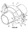
- Figure 4A illustrates another embodiment 11 of a coupling according to the invention.
- the contact surfaces 42 on the gripping bodies 36 and 38 have a convex shape. This permits them to engage the reaction surfaces 32 tangentially when the segments 12 and 14 are drawn toward one another, resulting in reaction forces which cause motion of the gripping bodies toward the central space.
- the reaction surfaces 32 are angularly oriented.
- Figure 4B shows another embodiment 13 wherein the reaction surfaces 32 have a convex shape and the contact surfaces 42 are angularly oriented. This again allows for tangential engagement between the reaction surfaces and the contact surfaces, resulting in reaction forces which cause motion of the gripping bodies toward the central space as the segments 12 and 14 are drawn toward each other.
- FIG. 5 shows an isometric exploded view of another coupling embodiment 50 according to the invention.
- Coupling 50 has gripping bodies 36 and 38 with contact surfaces 52 positioned on opposite sides of the gripping bodies. Again, the contact surfaces are angularly oriented with respect to the connection members 18 and interface with reaction surfaces 54 positioned on the connection members 18. Orientation angles 56 for the contact surfaces from about 30° to about 60° are advantageous for this coupling design. It is preferred that the orientation angle of the reaction surfaces 54 be approximately the same as the contact surfaces as shown in Figure 8 .
- coupling 50 Operation of coupling 50 is similar to that of coupling 10 described above.
- the segments 12 and 14 and the gripping bodies 36 and 38 are spaced outwardly away from the central space 16 so as to allow a pipe element to be inserted into the central space. Tightening of the fasteners as shown in Figure 7 draws the segments 12 and 14 toward one another and the central space, allowing the arcuate surfaces 28 to engage the pipe elements' outer surface. Interaction between the contact surfaces 52 on the gripping bodies 36 and 38 and the reaction surfaces 54 on the segments 12 and 14 forces the gripping bodies to move inwardly toward the central space as the fasteners 58 are tightened. The inward motion of the gripping bodies allows their gripping surfaces 40 to engage the pipe elements 30 as shown in Figure 8 .
- FIG 9 shows an exploded view of another coupling embodiment 60 according to the invention.
- Coupling 60 comprises coupling segments 12 and 14. The segments are arranged in facing relation and are joined end-to-end by connection members 18 positioned at opposite ends of each segment.
- the connection members comprise outwardly extending projections 20 which receive fasteners 58 that are adjustably tightenable. Tightening of the fasteners draws the coupling segments 12 and 14 toward one another and the central space 16.
- Each segment has inwardly facing arcuate surfaces 28 positioned in spaced relation to one another.
- the arcuate surfaces occupy positions between the ends of each segment.
- Reaction surfaces 32 are positioned in spaced relation at opposite ends of each coupling segment 12 and 14. The reaction surfaces face inwardly toward the central space 16 and extend in a tangential direction around the segments.
- the reaction surfaces are angularly oriented as described below.
- Gripping bodies 36 and 38 are positioned between the segments 12 and 14 at opposite ends of the coupling 60.
- Each gripping body has inwardly facing gripping surfaces 40 arranged in spaced relation.
- the gripping surfaces 40 align with respective arcuate surfaces 28 when the coupling is assembled as best shown in Figure 11 .
- each gripping body has contact surfaces 42 in spaced relation. Contact surfaces 42 face outwardly away from the central space 16 and engage respective reaction surfaces 32 on the segments 12 and 14.
- the contact surfaces on the gripping bodies cooperate with the reaction surfaces on the segments such that, when the segments are drawn toward one another, for example, by the tightening of fasteners 58, the gripping bodies are urged radially inwardly as explained further below.
- a seal 46 is positioned between the coupling segments 12 and 14 and the gripping bodies 36 and 38. Both the segments and gripping bodies have respective channels 62 and 64 positioned between the arcuate surfaces 28 and the gripping surfaces 40 which receive the seal.
- the inner circumference 66 of the seal 46 has inwardly facing sealing surfaces 68 and 70 which engage pipe elements joined by the coupling to form a fluid-tight seal.
- the seal 46 is sized so that, in an undeformed state, its outer circumferences 72 supports the segments 12 and 14 and the gripping bodies 36 and 38 in spaced apart relation sufficient for pipe elements to be inserted into the central space 16 without disassembling the coupling.
- the sealing member is a ring formed of an elastic, resilient maternal such as EPDM elastomer which deforms when the coupling segments are drawn toward one another by adjustably tightening the connection members 18.
- FIG 11 shows the pipe coupling 60 in its pre-assembled state ready for use.
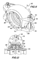
- pipe elements 30 are inserted into the sealing member 46 as shown in Figure 12 , so that the segments straddle facing end portions of the pipe elements.
- the pipe elements are inserted to an extent such that grooves 74 in the outer surfaces of the pipe elements align with the arcuate surfaces of the segments (not shown) and the gripping surfaces 40 of the gripping bodies 36 and 38. Insertion of the pipe elements to the proper depth may be facilitated by a pipe stop 76 positioned on the sealing member between the sealing surfaces 68 and 70. The pipe stop projects inwardly to engage the ends of the pipe elements and limit the insertion depth as desired.
- Figure 13 shows a cross-sectional view of the coupling 60 with pipe element 30 inserted. Attention is drawn to the reaction surfaces 32 on segments 12 and 14 engaging the contact surfaces 42 on gripping bodies 36 and 38. The reaction surfaces are angularly oriented so that when the fasteners 58 are tightened, drawing the segments 12 and 14 toward one another as shown in Figure 14 , the gripping bodies 36 and 38 are moved radially inwardly so that the gripping surfaces on the gripping bodies engage and grip the grooves 74 of the pipe elements 30 shown in Figure 12 . The motion of the segments 12 and 14 toward one another also causes the arcuate surfaces 28 (not shown) on each segment to engage and grip the grooves as well. The pipe elements are, thus, secured in end-to-end relation.
- the sealing member is deformed radially inwardly to force the sealing surfaces 68 and 70 into further engagement with the outer surfaces of the pipe elements.
- This configuration produces a relatively rigid joint.
- a more flexible joint can alternately be provided if the motion of the arcuate surfaces is limited so that they do not engage and clamp the floor of the groove.
- the travel of the gripping bodies is limited by the extent or length of the reaction surfaces and the contact surfaces. Limitation of motion of the arcuate surfaces on the segments toward the central space is preferably controlled by limiting the motion of the segments through contact of the connection members 18.
- the coupling embodiment 60 provides a substantially rigid joint for the pipe elements, i.e., the joint has significant stiffness about all three axes (bending, axial extension and torsion) to prevent significant angular deflection as well as axial movement (compression and extension) of the pipe elements relatively to one another. Torsional deflections are also inhibited.
- the rigidity of the joint is effected by the angularly oriented surfaces 78 and 80 positioned on each segment 12 and 14 adjacent to the connection members 18 as best shown in Figure 9 .
- the surfaces 78 and 80 on each segment have opposite slopes and are in facing relation with the angularly oriented surfaces on the adjoining segment.
- the gripping bodies 36 and 38 may be designed as shown in Figure 9 such that their end faces 84 and 86 are angularly oriented relative to the gripping surfaces 40.
- the angular orientation is best shown in Figure 10 for gripping body 36 which takes on a rhomboidal profile as a result.
- the end faces 84 and 86 engage inwardly projecting shoulders 88 on each segment 12 and 14 as the segments are drawn toward one another when forming a joint.
- the angular orientation of the end faces causes the gripping bodies 36 and 38 to rotate in opposite directions about an axis 90 as they are brought into contact with the shoulders 88.
- Axis 90 is substantially perpendicular to the pipe elements being joined by the coupling segments 12 and 14.
- the rotation of the gripping bodies causes the gripping surfaces 40 thereon to rotate and forcibly engage the sidewalls of the grooves in the pipe elements similar to the arcuate surfaces on the segments.
- the channels 64 in each gripping body are skewed in the opposite direction of rotation so that, when the gripping elements rotate about axis 90, the channels 64 will align with the sealing members so that essentially only radial compression results, i.e., there is no significant twisting of the sealing member about axis 90.
- Rotation of the gripping bodies 36 and 38 about axis 90 may also be achieved by angularly orienting the inwardly projecting shoulders 88 as shown in Figure 15 , the orientation angle 92 of the shoulder forcing rotation of the gripping bodies as the segments 12 and 14 are drawn together, forcing engagement between the shoulders 88 and the end faces 84 and 86 of the gripping bodies. It is also possible to combine the features of Figures 9 and 15 and have both the end faces 84 and 86 angularly oriented as well as the shoulders 88.
- FIG 16 shows an exploded view of another coupling embodiment 94 according to the invention.
- Coupling 94 is used to couple plain end pipe elements together, i.e., pipes having no grooves, beads, enlargements or other features near the ends to facilitate engagement with the coupling.
- Many of the components of this embodiment are similar to coupling 60 and will not be described in detail.
- the sealing member 46 shown in Figure 1 is not shown in Figure 6 for clarity, although the same or a similar sealing member is also used with coupling 94.
- Each retainer comprises an annular band 100 which has a plurality of flexible, resilient teeth 102.
- the teeth project radially inwardly for engagement with the pipe elements as described below.
- the teeth are also angularly oriented out of the plane of the band 100, with the teeth on retainer 96 being angled toward the teeth on retainer 98 and vice versa.
- the angular orientation of the teeth allows the pipe elements to be inserted into the coupling, but prevents the pipe elements from being withdrawn when the teeth forcibly engage the pipe elements as described below.
- Band 100 is split, as evidenced by the gap 104. This gap permits the band to be compressed radially to allow the teeth to engage the pipe elements.
- the retainers are received within grooves 106 and 108 in segments 12 and 14 and grooves 110 and 112 in the gripping bodies 36 and 38.
- the grooves in the segments align with the grooves in the gripping bodies.
- the segments 12 and 14 are drawn together and the gripping bodies 36 and 38 move inwardly in response to the interaction of the reaction surfaces 32 with the contact surfaces 42.
- the inward motion of the grooves 106, 108, 110 and 112 compresses the bands 100 of retainers 96 and 98 inwardly so that teeth 102 engage the surfaces of pipe elements 30.
- the teeth are angled they deflect inwardly and permit the pipe elements to be inserted into the coupling. But when force is applied which tends to remove the pipe elements from the coupling, the teeth prevent this motion due to the self-jamming characteristics of the angled teeth.
- Retainers 96 and 98 preferably have a plurality of tabs 114 which project outwardly from the band 100. As shown in Figure 16 , the tabs engage the grooves 106 and 108 of the segments as well as grooves 110 and 112 of the gripping bodies and provide a degree of radial flexibility to the retainer. This added flexibility permits the segments to be joined in what is known as "pad-to-pad" relation wherein the connection members 18 on the segments abut one another when the fasteners 58 are tightened in spite of dimensional variations in the segments and pipes.
- the segments join pad-to-pad as it provides a readily identifiable visual indication that the fasteners are fully tightened and thereby avoids the need for torquing the fasteners to a particular value as proof of completion of a fluid-tight joint. Avoiding the need for torque measurements simplifies installation of the coupling, as a torque wrench is not necessary.
- Couplings according to the invention realize an advantage through the use of the moving gripping bodies which allows them to be installed from the pre-assembled state easily using hand tools.
- the movable gripping bodies reduce the torque required to bring the segments together and grip the pipe elements to effect a fluid-tight joint.
Landscapes
- Engineering & Computer Science (AREA)
- General Engineering & Computer Science (AREA)
- Mechanical Engineering (AREA)
- Physics & Mathematics (AREA)
- Fluid Mechanics (AREA)
- Joints With Sleeves (AREA)
- Clamps And Clips (AREA)
- Quick-Acting Or Multi-Walled Pipe Joints (AREA)
- Joints Allowing Movement (AREA)
- Flanged Joints, Insulating Joints, And Other Joints (AREA)
- Joints With Pressure Members (AREA)
- Mutual Connection Of Rods And Tubes (AREA)
Claims (15)
- Rohrkopplung zum endseitigen Festlegen eines Endabschnitts eines Paars von Rohrelementen aneinander, wobei die Kopplung aufweist:ein Paar von endseitig verbindbaren Segmenten (12, 14), die zur Aufnahme der Rohrelemente einen zentralen Raum (16) umgeben, wobei jedes Segment (12, 14) ein Paar von zu einander beabstandete, bogenförmige Flächen (28) aufweist, wobei die bogenförmigen Flächen (28) dem zentralen Raum (16) gegenüber liegen und mit den Rohrelementen (30) in Eingriff bringbar sind;zumindest ein Verbindungselement (18), das an gegenüberliegenden Enden von jedem der Segmente zu liegen kommt, um die Segmente (12, 14) miteinander zu verbinden, wobei die Verbindungselemente (18) einstellbar verspannbar sind, um die Segmente in Eingriff mit den Rohrelementen (30) aufeinander zu zu ziehen, gekennzeichnet durch zumindest eine jeweilige Reaktionsfläche (32), die auf zumindest zwei der aufeinander zuweisenden Verbindungselemente (18) zu liegen kommt, wobei die Reaktionsflächen (32) zum zentralen Raum (16) weisen;ein Paar von Greifkörpern (36, 38);wobei das einstellbare Verspannen der Verbindungselemente (18) die Kopplungssegmente (12, 14) aufeinander zu zieht, wobei die Kontaktflächen (42) mit den Reaktionsflächen (32) interagieren, um den Greifkörper (36, 38) zum Eingriff der Greifflächen (40) mit den Rohrelementen (30) in den zentralen Raum (16) zu bewegen; undwobei:das Paar von Greifkörpern (36, 38) zwischen den Segmenten (12, 14) in Gegenüberlage zu einander zu liegen kommt, wobei die Greifkörper (36, 38) jeweils ein Paar beabstandet positionierte und zum zentralen Raum weisende Greifflächen (40) aufweisen; unddas erste Paar Kontaktflächen (42) in Gegenüberlage zu den Reaktionsflächen (32) auf jedem der Greifkörper (36, 38) zu liegen kommt.
- Rohrkopplung nach Anspruch 1, wobei die Verbindungselemente (18) ein Paar von Vorsprüngen (20) aufweisen, die sich von den Enden der Segmente (12, 14) nach außen erstrecken, wobei die Vorsprünge (20) dazu ausgelegt sind, zum einstellbaren Verbinden der Segmente (12, 14) miteinander Befestigungselemente (24, 26) aufzunehmen, wobei die Befestigungselemente (24, 26) zum Ziehen der bogenförmigen Flächen (28) der Segmente (12, 14) in Eingriff mit den Rohrelementen (30) einstellbar verspannbar sind.
- Rohrkopplung nach Anspruch 2, wobei die Reaktionsflächen (32) in Bezug auf die Vorsprünge (20) winkelmäßig ausgerichtet sind.
- Rohrkopplung nach Anspruch 3, wobei die Reaktionsflächen (32) unter einem Winkela) von etwa 30° bis etwa 60°; oderb) von etwa 45°ausgerichtet sind.
- Rohrkopplung nach Anspruch 3, wobei die Kontaktflächen (42):a) eine konvexe Form aufweisen; oderb) in Bezug auf die Vorsprünge (20) winkelmäßig ausgerichtet sind.
- Rohrkopplung nach Anspruch 3, wobei die Kontaktflächen (42):a) unter einem Winkel von etwa 30° bis etwa 60°;b) unter einem Winkel von etwa 45° in Bezug auf die Vorsprünge (20) winkelmäßig ausgerichtet sind; oderc) die Reaktionsflächen (32) eine konvexe Form aufweisen.
- Rohrkopplung nach Anspruch 1, wobei die Kontaktflächen (42) radial auswärts weg von dem zentralen Raum (16) vorstehen.
- Rohrkopplung nach Anspruch 1, außerdem aufweisend:a) ein zweites Paar Kontaktflächen (42), wobei die ersten und zweiten Paare Kontaktflächen (42) auf gegenüber liegenden Seiten des Greifkörpers (36, 38) zu liegen kommen; oderb) ein Dichtelement (46), das zwischen den Segmenten (12, 14) festgehalten ist und zwischen den bogenförmigen Flächen (28) zu liegen kommt, wobei das Dichtelement (46) einwärts weisende Dichtflächen aufweist, die zur Bildung einer fluiddichten Verbindung zwischen den Rohrelementen (30) mit den Rohrelementen (30) in Eingriff bringbar sind.
- Rohrkopplung nach Anspruch 1, wobei:die ersten und zweiten Reaktionsflächen (32) an gegenüber liegenden Enden von jedem Kopplungssegment (12, 14) beabstandet zu liegen kommen;die Greifflächen (40) mit den Rohrelementen (30) in Eingriff bringbar sind, wobei jede der Kontaktflächen (42) mit einer der Reaktionsflächen (32) der Segmente im Eingriff steht,wobei jeder der Greifkörper 36, 38) einander gegenüber liegende Stirnseiten (19) aufweist, wobei die Segmente (12, 14) einwärts vorspringende Schultern (21) aufweisen, die benachbart zu den Reaktionsflächen (32) zu liegen kommen, wobei die Schultern (21) mit den Stirnseiten (19) in Eingriff bringbar sind, wobei zumindest eine der Stirnseiten (19) oder die Schultern (21) winkelmäßig derart ausgerichtet ist, dass eine Drehung der Greifkörper (36, 38) um eine Achse im Wesentlichen senkrecht zu den Rohrelementen (30) veranlasst wird, wenn die Kopplungssegmente (12, 14) aufeinander zu gezogen werden; unddie Kontaktflächen (42) mit den Reaktionsflächen (32) interagieren, um die Greifkörper (36, 38) zum Eingriff der Greifflächen (40) mit den Rohrelementen (30) radial einwärts zu bewegen.
- Rohrkopplung nach Anspruch 9, wobei:a) die Reaktionsflächen (32) sich in tangentialer Richtung der Segmente (12, 14) erstrecken; oderb) die Kopplung zusätzlich ein Dichtelement (46) aufweist, das zwischen den Segmenten (12, 14) festgehalten ist und zwischen den bogenförmigen Flächen (28) zu liegen kommt, wobei das Dichtungselement (46) einwärts weisende Dichtflächen (68, 70) aufweist, die zur Bildung einer fluiddichten Verbindung zwischen den Rohrelementen (30) mit den Rohrelementen (30) in Eingriff bringbar sind.
- Rohrkopplung nach Anspruch 9, wobei die Verbindungselemente (18) ein Paar Vorsprünge (20) aufweisen, die sich von den Enden jedes der Segmente (12, 14) auswärts erstrecken, wobei die Vorsprünge (20) dazu ausgelegt sind, Befestigungselemente (24, 26) zum gegenseitigen, einstellbaren Verbinden der Segmente (12, 14) aufzunehmen, wobei die Befestigungselemente (24, 26) zum Ziehen der bogenförmigen Flächen (28) der Segmente (12, 14) in Eingriff mit den Rohrelementen (30) einstellbar verspannbar sind.
- Rohrkopplung nach Anspruch 9, wobei die Segmente (12, 14) außerdem ein Paar winkelmäßig ausgerichteter Flächen (32) aufweisen, die benachbart zu jedem der Verbindungselemente (18) zu liegen kommen, wobei die winkelmäßig ausgerichteten Flächen (32) auf jedem der Segmente (12, 14) entgegengesetzte Neigungen aufweisen, wobei die winkelmäßig ausgerichteten Flächen (32) auf einem der Segmente (12, 14) zu den winkelmäßig ausgerichteten Flächen (32) auf dem anderen der Segmente (12, 14) weisen, wobei die winkelmäßig ausgerichteten Segmente miteinander im Eingriff stehen, wenn die Segmente (12, 14) aufeinander zu gezogen werden und die Segmente (12, 14) veranlassen, sich um eine Achse im Wesentlichen senkrecht zu den Rohrelementen (30) relativ zueinander zu drehen.
- Rohrkopplung nach Anspruch 9, wobei:a) die Greifkörper (36, 38) einen Kanal (62, 64) aufweisen, der dazu ausgelegt ist, ein Dichtungselement (46) aufzunehmen, wobei der Kanal (62, 64) relativ zu den Greifflächen (40) schräg verläuft, um bei einer Drehung der Greifkörper (36, 38) im Wesentlichen mit dem Dichtungselement (46) zu fluchten; oderb) die Stirnseiten (19) in Bezug auf die Greiffläche (40) winkelmäßig ausgerichtet sind; oderc) die Schultern (21) in Bezug auf die bogenförmigen Flächen (28) winkelmäßig ausgerichtet sind.
- Rohrkopplung nach Anspruch 1, wobei:jedes Segment (12, 14) beabstandete und zum zentralen Raum (16) weisende erste und zweite Nuten aufweist;zueinander beabstandete erste und zweite Reaktionsflächen (32) an gegenüber liegenden Enden von jedem Kopplungssegment (12, 14) zu liegen kommen;jeder der Greifkörper (36, 38) beabstandete und zum zentralen Raum (16) weisende erste und zweite bogenförmige Nuten aufweist, wobei jeder der Greifkörper (36, 38) mehrere zu den Reaktionsflächen (32) weisende Kontaktflächen (42) aufweist, wobei jede der Kontaktflächen mit einer der Reaktionsflächen (32) auf jedem der Segmente (12, 14) im Eingriff steht; unddie Kopplung (94) außerdem erste und zweite Halter (96, 98) aufweist, wobei jeder der Halter (96, 98) ein ringförmiges Band (100) mit mehreren sich radial einwärts erstreckenden Zähnen (102) aufweist, wobei jedes ringförmige Band (100) derart unterteilt ist, dass eine radiale Bewegung der Zähne (102) möglich ist, wenn das Band (100) radial zusammengedrückt wird, wobei der erste Halter (96) in den ersten Nuten (106) in den Kopplungssegmenten (12, 14) und den Greifkörpern (36, 38) aufgenommen ist, wobei der zweite Halter (98) in den zweiten Nuten (108) in den Kopplungssegmenten (12, 14) und den Greifkörpern (36, 38) aufgenommen ist, wobei die Zähne (102) des ersten Halters (96) in Richtung auf die Zähne (102) des zweiten Halters (98) winkelmäßig ausgerichtet sind, und wobei die Zähne (102) des zweiten Halters (98) winkelmäßig in Richtung auf die Zähne (102) des ersten Halters ausgerichtet sind; undwobei das einstellbare Verspannen der Verbindungselemente (18) die Kopplungssegmente (12, 14) aufeinander zu zieht, wobei die Kontaktflächen (42) mit den Reaktionsflächen (32) interagieren, um die Greifkörper (36, 38) zum Drücken der Halter (96, 98) in Eingriff mit den Rohrelementen (30) radial einwärts zu bewegen.
- Rohrkopplung nach Anspruch 14, wobei:a) die Reaktionsflächen (32) sich in einer tangentialen Richtung der Segmente (12, 14) erstrecken; oderb) die Kopplung außerdem eine Zunge (114) aufweist, die von zumindest einem der Halter (96, 98) radial auswärts vorsteht, wobei die Zunge (114) in eine der Nuten (106, 108) eingreift, wobei die Zunge (114) das radiale Zusammendrücken von einem der Halter (96, 98) zum Eingriff der auf ihm vorgesehenen Zähne (102) mit einem der Rohrelemente (30) fördert.
Priority Applications (1)
| Application Number | Priority Date | Filing Date | Title |
|---|---|---|---|
| PL08755442T PL2153102T3 (pl) | 2007-05-15 | 2008-05-14 | Złącze rurowe posiadające ruchome korpusy zaciskowe |
Applications Claiming Priority (2)
| Application Number | Priority Date | Filing Date | Title |
|---|---|---|---|
| US93800307P | 2007-05-15 | 2007-05-15 | |
| PCT/US2008/063587 WO2008144332A1 (en) | 2007-05-15 | 2008-05-14 | Pipe coupling having movable gripping bodies |
Publications (3)
| Publication Number | Publication Date |
|---|---|
| EP2153102A1 EP2153102A1 (de) | 2010-02-17 |
| EP2153102A4 EP2153102A4 (de) | 2010-05-05 |
| EP2153102B1 true EP2153102B1 (de) | 2012-10-17 |
Family
ID=40026760
Family Applications (1)
| Application Number | Title | Priority Date | Filing Date |
|---|---|---|---|
| EP08755442A Active EP2153102B1 (de) | 2007-05-15 | 2008-05-14 | Rohrkopplung mit beweglichen greifelementen |
Country Status (13)
| Country | Link |
|---|---|
| US (6) | US7950701B2 (de) |
| EP (1) | EP2153102B1 (de) |
| JP (3) | JP5427172B2 (de) |
| KR (1) | KR101284635B1 (de) |
| CN (2) | CN102878366B (de) |
| AU (1) | AU2008255079B2 (de) |
| CA (2) | CA2775758C (de) |
| ES (1) | ES2394947T3 (de) |
| IL (2) | IL201668A (de) |
| MX (1) | MX2009012329A (de) |
| PL (1) | PL2153102T3 (de) |
| TW (3) | TWI354080B (de) |
| WO (1) | WO2008144332A1 (de) |
Families Citing this family (108)
| Publication number | Priority date | Publication date | Assignee | Title |
|---|---|---|---|---|
| US7712796B2 (en) * | 2004-05-14 | 2010-05-11 | Victaulic Company | Deformable mechanical pipe coupling |
| US7726703B2 (en) | 2006-06-07 | 2010-06-01 | Victaulic Company | Deformable pipe coupling having multiple radii of curvature |
| USD621483S1 (en) * | 2009-10-19 | 2010-08-10 | Victaulic Company | Pipe coupling segment |
| USD621916S1 (en) | 2009-10-19 | 2010-08-17 | Victaulic Company | Pipe coupling |
| USD621482S1 (en) | 2009-10-19 | 2010-08-10 | Victaulic Company | Pipe coupling segment |
| USD621917S1 (en) | 2009-10-19 | 2010-08-17 | Victaulic Company | Pipe coupling |
| US7950701B2 (en) | 2007-05-15 | 2011-05-31 | Victaulic Company | Pipe coupling having movable gripping bodies |
| US8789605B2 (en) * | 2008-04-30 | 2014-07-29 | Parker-Hannifin Corporation | Riser clamp |
| US8282136B2 (en) | 2008-06-30 | 2012-10-09 | Mueller International, Llc | Slip on groove coupling with multiple sealing gasket |
| JP5314992B2 (ja) * | 2008-10-07 | 2013-10-16 | コスモ工機株式会社 | フランジ継手漏洩防止装置 |
| US8136847B2 (en) * | 2009-05-14 | 2012-03-20 | Victaulic Company | Coupling having angularly oriented shoulder surfaces |
| MY164390A (en) * | 2009-10-27 | 2017-12-15 | Tyco Fire Products Lp | Systems and methods for pipe couplings |
| US8621741B2 (en) * | 2009-11-30 | 2014-01-07 | Howard Hagiya | 4-way compression grooved coupling |
| US9285061B2 (en) * | 2009-12-14 | 2016-03-15 | The Victaulic Company of Japan | Housing-type pipe joint |
| CL2010000283A1 (es) | 2010-03-29 | 2012-01-13 | Vimar Soc Comercial Limitada | Elemento de copla para union de canerias, que posee una camisa semi-tubular, con un primer y segundo bordes con primera y segunda pestaña respectivas, ambas con perforaciones, y la cara frontal posee un reborde superior con una pestaña semicircular con perforaciones frontales y un canal semicircular; metodo de montaje. |
| CN102102761A (zh) * | 2010-06-23 | 2011-06-22 | 谢金婵 | 带限位舌凸压力反应式密封垫圈 |
| US20120112026A1 (en) * | 2010-11-10 | 2012-05-10 | Kimball Physics, Inc. | Apparatus for supporting an assembly of conflat-connected ultra-high vacuum modules |
| BR112013011398B1 (pt) | 2010-12-02 | 2021-11-03 | Victaulic Company | Elementos de tubulação tendo um diâmetro externo e pelo menos uma extremidade e combinação de um acoplamento e pelo menos um elemento de tubulação |
| US8556302B2 (en) * | 2011-04-05 | 2013-10-15 | Victaulic Company | Pivoting pipe coupling having a movable gripping body |
| US20120274063A1 (en) * | 2011-04-29 | 2012-11-01 | Kennedy Jr Harold | Pipe connecting apparatus |
| JP5991787B2 (ja) * | 2011-08-22 | 2016-09-14 | ビクターリック カンパニー | 伸縮継手 |
| USD696751S1 (en) | 2011-10-27 | 2013-12-31 | Mueller International, Llc | Slip-on gasket |
| USD680630S1 (en) | 2011-11-21 | 2013-04-23 | Mueller International, Llc | Slip-on coupling assembly |
| USD680629S1 (en) | 2011-11-21 | 2013-04-23 | Mueller International, Llc | Slip-on coupling segment |
| US9395024B2 (en) | 2011-11-21 | 2016-07-19 | Victaulic Company | Coupling having gasket pocket of varying depth |
| US20130125373A1 (en) | 2011-11-21 | 2013-05-23 | Philip W. Bancroft | Coupling with projections having angularly oriented surface portions |
| US9500307B2 (en) | 2012-01-20 | 2016-11-22 | Mueller International, Llc | Slip-on coupling gasket |
| US9039046B2 (en) | 2012-01-20 | 2015-05-26 | Mueller International, Llc | Coupling with tongue and groove |
| US9194516B2 (en) | 2012-01-20 | 2015-11-24 | Mueller International, Llc | Slip-on coupling |
| US9534715B2 (en) | 2012-01-20 | 2017-01-03 | Mueller International, Llc | Coupling gasket with multiple sealing surfaces |
| US8820795B2 (en) * | 2012-02-02 | 2014-09-02 | Victaulic Company | Fitting for joining pipe elements |
| KR101294759B1 (ko) | 2012-05-17 | 2013-08-09 | 한미실업 주식회사 | 나선관의 연결 조립구조 |
| CA2877703A1 (en) * | 2012-06-28 | 2014-01-03 | Victaulic Company | Pipe repair clamp assembly |
| KR101300539B1 (ko) * | 2012-09-28 | 2013-09-02 | 천영민 | 양방향 확관형 배관 및 그 조인트 구조 |
| US9168585B2 (en) | 2012-11-02 | 2015-10-27 | Mueller International, Llc | Coupling with extending parting line |
| US10578234B2 (en) * | 2013-05-02 | 2020-03-03 | Victaulic Company | Coupling having arcuate stiffness ribs |
| CN103277603B (zh) * | 2013-05-06 | 2015-12-02 | 中国长江电力股份有限公司 | 一种弹簧预紧管箍 |
| MX369972B (es) * | 2013-12-23 | 2019-11-27 | Victaulic Co Of America | Acoplamiento de anillo dividido. |
| US20190331265A1 (en) | 2013-12-23 | 2019-10-31 | Victaulic Company | Split Ring Coupling and Fitting |
| JP5953586B2 (ja) * | 2014-04-11 | 2016-07-20 | 株式会社トヨックス | 管継手 |
| US9551444B2 (en) * | 2015-01-19 | 2017-01-24 | Eliezer Krausz Industrial Development Ltd. | Pipe coupling capsulation assembly |
| US9651172B2 (en) | 2015-03-16 | 2017-05-16 | Michael Neal McNamee, JR. | Rotatable adjustable segmented clamp |
| USD787305S1 (en) * | 2015-03-16 | 2017-05-23 | Michael Neal McNamee, JR. | Segmented clamp |
| CN104876174B (zh) * | 2015-06-09 | 2018-03-27 | 芜湖瑞泰精密机械有限公司 | 一种防冻液加注接头结构 |
| EP3334937B1 (de) | 2015-08-11 | 2024-06-26 | Carrier Corporation | Schraubenverdichter-economiser-plenum zur pulsationsreduktion |
| RU2723469C2 (ru) * | 2015-08-11 | 2020-06-11 | Кэрриер Корпорейшн | Компрессор, паровая компрессионная установка и способы их эксплуатации и сборки |
| JP3201323U (ja) * | 2015-09-18 | 2015-12-03 | 株式会社永島製作所 | 管継手 |
| AU2016322808B2 (en) * | 2015-09-18 | 2019-05-30 | Victaulic Company | Valve and coupling |
| CN108138775B (zh) | 2015-10-02 | 2020-11-20 | 开利公司 | 螺杆压缩机谐振器阵列 |
| JP6742709B2 (ja) * | 2015-10-05 | 2020-08-19 | 日本ヴィクトリック株式会社 | 伸縮管継手構造およびその施工方法 |
| ES2810705T3 (es) * | 2015-11-23 | 2021-03-09 | Victaulic Co Of America | Válvula y acoplamiento de válvula con ejes ahusados inversos |
| US9903515B2 (en) * | 2015-12-09 | 2018-02-27 | Victaulic Company | Seal with lip projections |
| JP6710766B2 (ja) | 2015-12-28 | 2020-06-17 | ビクターリック カンパニー | アダプタカップリング |
| US10533688B2 (en) | 2016-05-16 | 2020-01-14 | Victaulic Company | Coupling having tabbed retainer |
| US10605394B2 (en) | 2016-05-16 | 2020-03-31 | Victaulic Company | Fitting having tabbed retainer and observation apertures |
| US10859190B2 (en) | 2016-05-16 | 2020-12-08 | Victaulic Company | Sprung coupling |
| SG10202011359UA (en) * | 2016-05-19 | 2020-12-30 | Controlflow Inc | Metal-to-metal well equipment seal |
| CN107435674A (zh) * | 2016-05-25 | 2017-12-05 | 上海共联通信信息发展有限公司 | 一种用于医疗流体泵送系统中的圆形紧固件 |
| CA3225044C (en) | 2016-06-13 | 2025-10-07 | Hubbell Incorporated | Load-carrying clamp for transferring loads to a tree |
| USD803674S1 (en) * | 2016-08-04 | 2017-11-28 | National Products, Inc. | Mounting device |
| US10792873B2 (en) * | 2016-09-23 | 2020-10-06 | The Uab Research Foundation | Fastening devices for landing string buoyancy and other solutions |
| US10641419B2 (en) | 2016-12-14 | 2020-05-05 | Anvil International, Llc | Pipe coupling with closed ring |
| US11378208B2 (en) * | 2016-12-14 | 2022-07-05 | ASC Engineered Solutions, LLC | Pipe couplings |
| CA3049982C (en) * | 2017-02-02 | 2021-07-06 | Victaulic Company | Mechanical coupling for mechanical and structural tubing |
| US10962157B2 (en) | 2017-04-18 | 2021-03-30 | Cobalt Coupler Systems, LLC | Coupler |
| US11060646B2 (en) | 2017-04-18 | 2021-07-13 | Cobalt Coupler Systems, LLC | Coupler |
| US11560972B2 (en) | 2017-04-18 | 2023-01-24 | Cobalt Coupler Systems, LLC | Oil and gas pipe connector |
| US10527219B2 (en) | 2017-06-02 | 2020-01-07 | National Products, Inc. | Mounting track for retaining a mount assembly |
| US10982807B2 (en) | 2017-06-02 | 2021-04-20 | National Products, Inc. | Handle with mounting track for receiving a mount assembly |
| US10155306B1 (en) | 2017-06-02 | 2018-12-18 | National Products, Inc. | Handle with mounting track for receiving a mount assembly |
| US11085579B2 (en) | 2017-06-02 | 2021-08-10 | National Products, Inc. | Mounting track for retaining a mount assembly |
| US10429002B2 (en) | 2017-06-19 | 2019-10-01 | National Products, Inc. | Top-loading mounting track for receiving a mount assembly |
| US10448626B2 (en) | 2017-07-14 | 2019-10-22 | National Products, Inc. | Fishing rod holder with a top mount receptacle for receiving a device mount |
| US10378690B2 (en) | 2017-07-14 | 2019-08-13 | National Products, Inc. | Systems and methods for making and using mounts for receiving objects and coupling to surfaces |
| US11209107B2 (en) | 2017-07-28 | 2021-12-28 | ASC Engineered Solutions, LLC | Pre-assembled coupling assembly with cap |
| US11268638B2 (en) | 2017-07-28 | 2022-03-08 | ASC Engineered Solutions, LLC | Pre-assembled coupling assemblies with pipe fitting |
| USD861834S1 (en) * | 2017-08-24 | 2019-10-01 | Kerr Machine Co. | Valve seat |
| US10473150B2 (en) | 2018-04-17 | 2019-11-12 | National Products, Inc. | Mounting arrangement for attachment to device sockets and methods of making and using |
| KR102100634B1 (ko) | 2018-08-30 | 2020-04-14 | 주식회사 코리아조인트 | 체결 상태를 체크할 수 있는 파이프 커플링 |
| US10781944B2 (en) | 2018-09-27 | 2020-09-22 | Anvil International, Llc | Pipe clamp |
| US11448346B2 (en) | 2018-09-28 | 2022-09-20 | ASC Engineered Solutions, LLC | Pipe coupling |
| USD899222S1 (en) | 2019-01-07 | 2020-10-20 | National Products, Inc. | Mounting device with attached ball |
| USD891906S1 (en) | 2019-01-07 | 2020-08-04 | National Products, Inc. | Mounting device |
| USD891905S1 (en) | 2019-01-07 | 2020-08-04 | National Products, Inc. | Mounting device with ball |
| US11913572B2 (en) | 2019-03-13 | 2024-02-27 | Team Industrial Services, Inc. | Hot bolt clamp |
| US11371630B2 (en) * | 2019-03-29 | 2022-06-28 | ASC Engineered Solutions, LLC | Pivot clip |
| US11421804B2 (en) | 2019-04-19 | 2022-08-23 | Aalberts integrated piping systems APAC, Inc. | Quick installation coupling |
| KR102098328B1 (ko) * | 2019-05-17 | 2020-04-07 | 주식회사 뉴아세아조인트 | 파이프 연결용 커플링 어셈블리 및 이의 제조 방법 |
| KR102332394B1 (ko) * | 2019-05-23 | 2021-11-29 | (주)뉴아세아조인트 | 스프링클러 시스템 |
| CA188984S (en) * | 2019-07-30 | 2020-11-13 | Shur Fit Products Ltd | Coupling covering |
| EP3816621A1 (de) * | 2019-10-30 | 2021-05-05 | Georg Fischer Rohrleitungssysteme AG | Prüfung einer muffenschweissung |
| US11781683B2 (en) | 2019-11-15 | 2023-10-10 | Victaulic Company | Shrouded coupling |
| JP7213997B2 (ja) * | 2020-03-31 | 2023-01-27 | 株式会社三五 | ハウジング形管継手 |
| US11635155B2 (en) | 2020-05-08 | 2023-04-25 | National Products, Inc. | Adapter for attachment to a track or other surface or for receiving devices having different shaft spline arrangements |
| US12253195B2 (en) * | 2020-11-06 | 2025-03-18 | Victaulic Company | Coupling having visual installation indicators |
| EP4241007B1 (de) | 2020-11-06 | 2026-04-29 | Victaulic Company | Kupplung mit rotationsbegrenzten segmenten |
| US20220213993A1 (en) * | 2021-01-05 | 2022-07-07 | Howard Hagiya | Grooved-End Rubber Expansion Joint with 4-Way Compression Grooved Coupling |
| US20220341527A1 (en) * | 2021-04-27 | 2022-10-27 | Victaulic Company | Mechanical Outlet |
| MX2024003999A (es) * | 2021-10-01 | 2024-04-26 | Victaulic Co Of America | Junta y acoplamiento de estabilidad mejorada. |
| CR20240258A (es) | 2021-12-17 | 2024-09-04 | Lubrizol Advanced Mat Inc | Aparatos de tubería, dispositivos de acoplamiento y métodos campo |
| USD1034925S1 (en) | 2022-03-30 | 2024-07-09 | Ipex Technologies Inc. | Pipe-to-pipe connection |
| USD1034921S1 (en) | 2022-03-30 | 2024-07-09 | Ipex Technologies Inc. | Pipe-to-fitting connection |
| CN115199837B (zh) * | 2022-06-29 | 2023-11-24 | 江苏瑞阳环保有限公司 | 一种基于多重密封装置的节能型防洪用泵车结构 |
| JP7401937B1 (ja) * | 2022-07-15 | 2023-12-20 | 株式会社トヨックス | 管継手 |
| US12181083B2 (en) * | 2022-07-21 | 2024-12-31 | Applied System Technologies, Inc. | Pipe coupling |
| CN116219782A (zh) * | 2023-01-17 | 2023-06-06 | 中国十七冶集团有限公司 | 一种大直径钢拉索调整工具及其使用方法 |
| US12305799B2 (en) | 2023-04-19 | 2025-05-20 | National Products, Inc. | Vibration dampening mounts and methods of making and using |
| KR102817821B1 (ko) * | 2024-07-05 | 2025-06-09 | 주식회사 하이스텐 | 배관 커플링 |
Family Cites Families (65)
| Publication number | Priority date | Publication date | Assignee | Title |
|---|---|---|---|---|
| US591796A (en) * | 1897-10-12 | Chusetts | ||
| US711946A (en) * | 1899-12-06 | 1902-10-28 | Sanitary Coupling Company | Water-closet. |
| US649971A (en) * | 1900-01-05 | 1900-05-22 | Marcus Lafeyette Warman | Gate-operating mechanism. |
| US1004634A (en) * | 1909-10-06 | 1911-10-03 | Safety Car Heating & Lighting | Hose appliance. |
| US1662954A (en) * | 1922-07-10 | 1928-03-20 | Broido Anna G Freedman | Pipe joint |
| US1532596A (en) * | 1923-07-18 | 1925-04-07 | Peter Madsen | Hose clamp |
| US1791810A (en) * | 1927-08-11 | 1931-02-10 | Furman Eugene Clay | Fluid-tight joint |
| US1821863A (en) * | 1929-11-01 | 1931-09-01 | Wylie G Wilson | Fluid tight joint and method of making |
| US1930194A (en) | 1930-06-28 | 1933-10-10 | Stephen V Dillon | Pipe coupling |
| US2028182A (en) | 1932-04-28 | 1936-01-21 | Jr Ferd Barnickol | Coupling |
| US2005056A (en) * | 1934-05-26 | 1935-06-18 | Gustin Bacon Mfg Co | Pipe coupling |
| US2182797A (en) * | 1938-03-15 | 1939-12-12 | Stephen V Dillon | Gripping and coupling means |
| US2165920A (en) * | 1938-03-17 | 1939-07-11 | Us Stoneware Co | Pipe joint |
| US2512741A (en) * | 1945-04-17 | 1950-06-27 | Howard W Goodall | Hose coupling |
| US2473046A (en) | 1945-11-29 | 1949-06-14 | Jr Charles Adams | Pipe clamp |
| US3078108A (en) | 1959-08-05 | 1963-02-19 | Joseph B Smith | Split coupling |
| US3003793A (en) | 1960-04-14 | 1961-10-10 | Edmund W Pitt | Longitudinally divided sleeved pipe coupling |
| US3116078A (en) | 1961-07-18 | 1963-12-31 | Bernard F Scherer | Coupling having annularly arranged u-shaped gripping members retained against movement in sleeve |
| US3351352A (en) | 1962-02-27 | 1967-11-07 | Victaulic Co Of America | Gasket for pipe joint |
| US3249371A (en) * | 1963-10-14 | 1966-05-03 | Imp Eastman Corp | Full grip clamp |
| US3329446A (en) | 1966-08-18 | 1967-07-04 | Automatic Sprinkler Corp | Pipe coupling |
| US3479066A (en) * | 1967-07-03 | 1969-11-18 | Morris Gittleman | Pipe coupling |
| US4417755A (en) | 1974-10-07 | 1983-11-29 | Familian Corp. | Pipe coupling |
| ZA751105B (en) * | 1974-10-07 | 1976-01-28 | Familian Corp Mg Coupling Divi | Pipe coupling |
| JPS57161391A (en) | 1981-03-26 | 1982-10-04 | Isuzu Fishing Reel Mfg | Tube body connector |
| US4611839A (en) | 1983-07-12 | 1986-09-16 | Victaulic Company Of America | Self-adjusting pipe clamp and coupling |
| US4639020A (en) | 1983-07-12 | 1987-01-27 | Victaulic Company Of America | Self-adjusting pipe clamp and coupling |
| US4611835A (en) * | 1984-02-17 | 1986-09-16 | Familian Corp. | Pipe coupling |
| GB2171483B (en) * | 1985-02-18 | 1989-02-01 | British Gas Plc | Pipe repair clamp |
| DE3524621A1 (de) | 1985-07-10 | 1987-01-15 | Rasmussen Gmbh | Rohrkupplung |
| JPS6230084U (de) * | 1985-08-08 | 1987-02-23 | ||
| JPH041431Y2 (de) * | 1985-10-02 | 1992-01-17 | ||
| DE68905254T2 (de) | 1988-07-16 | 1993-08-12 | Peart E & Co Ltd | Eine rohrverbindung bzw. verschlusseinrichtung. |
| US5058931A (en) | 1988-11-28 | 1991-10-22 | Gustin-Bacon Division, A Division Of Tyler Pipe | Clamp with teeth for grooved pipes |
| GB8830202D0 (en) | 1988-12-23 | 1989-02-22 | Parkfield Group Plc | Pipe coupling |
| GB2240600B (en) * | 1990-02-02 | 1993-04-21 | Peart E & Co Ltd | A pipe repair or jointing collar |
| GB2253451B (en) * | 1991-02-23 | 1995-01-11 | Glynwed Consumer & Building | Pipe coupling |
| US5161836A (en) * | 1992-01-23 | 1992-11-10 | Mckinnon Robert M | Pipe connecting apparatus |
| US5286064A (en) | 1992-04-02 | 1994-02-15 | Bridges Donald Y | Sealing plate for a pipe coupling |
| JP2598620Y2 (ja) * | 1993-06-17 | 1999-08-16 | 日本鋼管継手株式会社 | ハウジング型管継手 |
| US5605357A (en) * | 1995-06-05 | 1997-02-25 | M&Fc Holding Co. | Pipe collar |
| US5769467A (en) * | 1995-10-10 | 1998-06-23 | Bridges; Donald Y. | Pipe couplings for misaligned or out-of-round pipes and expanding/contracting pipes |
| GB2310903B (en) * | 1996-03-05 | 1999-12-15 | Avk Mfg Ltd | A pipe repair or jointing collar |
| US5729582A (en) * | 1996-05-31 | 1998-03-17 | Ham; Young S. | Method and apparatus for determining both density and atomic number of a material composition using Compton scattering |
| US5758907A (en) | 1996-07-26 | 1998-06-02 | Victaulic Company Of America | Mis-adjustment limiting segmented pipe coupling |
| US5722701A (en) | 1996-12-04 | 1998-03-03 | Choi; Sang-Min | Method and assembly for joining pipes |
| DE19802676C1 (de) * | 1998-01-24 | 1999-05-06 | Rasmussen Gmbh | Spannbare Rohrkupplung |
| DE19901663C2 (de) * | 1999-01-18 | 2001-02-22 | Rasmussen Gmbh | Rohrkupplung |
| JP3546250B2 (ja) * | 1999-05-24 | 2004-07-21 | 東拓工業株式会社 | 波形管用継手 |
| US6499771B1 (en) | 2000-07-18 | 2002-12-31 | Victaulic Company Of America | Mechanical pipe coupling with toothed retainer |
| US7107662B1 (en) * | 2000-12-21 | 2006-09-19 | Gene W. Arant, as Trustee | Method and a coupler for joining two steel pipes |
| US20030062718A1 (en) * | 2001-09-28 | 2003-04-03 | Central Sprinkler Corporation | Ferrous pipe couplings and prelubricated coupling gaskets |
| FR2833065B1 (fr) * | 2001-12-05 | 2004-09-03 | Caillau Ets | Systeme de serrage pour le raccordement etanche de deux tubes ayant des surfaces d'appui |
| GB2401157B (en) | 2002-02-20 | 2005-10-26 | Taylor Kerr | Anchoring device for pipe coupling |
| GB2389395B (en) * | 2002-06-07 | 2006-02-15 | Taylor Kerr | Pipe coupling |
| JP4241827B2 (ja) * | 2003-07-28 | 2009-03-18 | ゲン キム,ス | フランジを用いた管継手装置 |
| US7712796B2 (en) | 2004-05-14 | 2010-05-11 | Victaulic Company | Deformable mechanical pipe coupling |
| US7086131B2 (en) | 2004-05-14 | 2006-08-08 | Victaulic Company | Deformable mechanical pipe coupling |
| TWI250054B (en) | 2004-06-08 | 2006-03-01 | Metal Ind Res & Dev Ct | A method for manufacturing tubular structural member |
| US20060103135A1 (en) * | 2004-11-18 | 2006-05-18 | Michael Scott | Exhaust pipe coupling |
| JP4699150B2 (ja) * | 2005-09-16 | 2011-06-08 | 日本ヴィクトリック株式会社 | ハウジング形管継手 |
| IL174110A0 (en) * | 2006-03-05 | 2006-08-01 | Krausz Metal Ind Ltd | Pipes coupling with integrated grip |
| US7950701B2 (en) | 2007-05-15 | 2011-05-31 | Victaulic Company | Pipe coupling having movable gripping bodies |
| WO2009102698A1 (en) * | 2008-02-12 | 2009-08-20 | Victaulic Company | Couplings having stiffening ribs and keys with oppositely disposed camming surfaces |
| US8556302B2 (en) * | 2011-04-05 | 2013-10-15 | Victaulic Company | Pivoting pipe coupling having a movable gripping body |
-
2008
- 2008-05-13 US US12/119,661 patent/US7950701B2/en not_active Ceased
- 2008-05-14 CA CA2775758A patent/CA2775758C/en active Active
- 2008-05-14 CN CN201210269704.XA patent/CN102878366B/zh active Active
- 2008-05-14 CA CA2686708A patent/CA2686708C/en active Active
- 2008-05-14 TW TW100104195A patent/TWI354080B/zh active
- 2008-05-14 JP JP2010508555A patent/JP5427172B2/ja not_active Expired - Fee Related
- 2008-05-14 TW TW100125348A patent/TWI453354B/zh active
- 2008-05-14 AU AU2008255079A patent/AU2008255079B2/en active Active
- 2008-05-14 MX MX2009012329A patent/MX2009012329A/es active IP Right Grant
- 2008-05-14 WO PCT/US2008/063587 patent/WO2008144332A1/en not_active Ceased
- 2008-05-14 KR KR1020097025913A patent/KR101284635B1/ko active Active
- 2008-05-14 PL PL08755442T patent/PL2153102T3/pl unknown
- 2008-05-14 CN CN2008800161824A patent/CN101715526B/zh active Active
- 2008-05-14 EP EP08755442A patent/EP2153102B1/de active Active
- 2008-05-14 TW TW097117759A patent/TWI352786B/zh active
- 2008-05-14 ES ES08755442T patent/ES2394947T3/es active Active
-
2009
- 2009-10-21 IL IL201668A patent/IL201668A/en active IP Right Grant
-
2011
- 2011-01-21 US US13/011,199 patent/US8312616B2/en active Active
- 2011-05-23 US US13/113,124 patent/US8177263B2/en active Active
- 2011-08-29 JP JP2011185812A patent/JP5385351B2/ja not_active Expired - Fee Related
-
2012
- 2012-03-08 US US13/415,086 patent/USRE45304E1/en active Active
- 2012-05-14 US US13/470,522 patent/US8517430B2/en active Active
- 2012-09-11 IL IL221884A patent/IL221884A/en active IP Right Grant
- 2012-10-11 JP JP2012225704A patent/JP5406971B2/ja active Active
-
2013
- 2013-07-24 US US13/949,626 patent/US8979138B2/en active Active
Also Published As
Similar Documents
| Publication | Publication Date | Title |
|---|---|---|
| EP2153102B1 (de) | Rohrkopplung mit beweglichen greifelementen | |
| US9388922B2 (en) | Pivoting pipe coupling having a movable gripping body | |
| AU2014202154B2 (en) | Pipe coupling having movable gripping bodies | |
| AU2012205150B2 (en) | Pipe coupling having movable gripping bodies | |
| HK1143626B (en) | A pipe coupling for securing end portions of a pair of pipe elements together end-to-end | |
| HK1181104B (en) | Pipe coupling for securing end portions of a pair of pipe elements together end-to-end |
Legal Events
| Date | Code | Title | Description |
|---|---|---|---|
| PUAI | Public reference made under article 153(3) epc to a published international application that has entered the european phase |
Free format text: ORIGINAL CODE: 0009012 |
|
| 17P | Request for examination filed |
Effective date: 20091201 |
|
| AK | Designated contracting states |
Kind code of ref document: A1 Designated state(s): AT BE BG CH CY CZ DE DK EE ES FI FR GB GR HR HU IE IS IT LI LT LU LV MC MT NL NO PL PT RO SE SI SK TR |
|
| AX | Request for extension of the european patent |
Extension state: AL BA MK RS |
|
| A4 | Supplementary search report drawn up and despatched |
Effective date: 20100406 |
|
| 17Q | First examination report despatched |
Effective date: 20100602 |
|
| DAX | Request for extension of the european patent (deleted) | ||
| REG | Reference to a national code |
Ref country code: DE Ref legal event code: R079 Ref document number: 602008019465 Country of ref document: DE Free format text: PREVIOUS MAIN CLASS: F16L0017060000 Ipc: F16L0017040000 |
|
| RIC1 | Information provided on ipc code assigned before grant |
Ipc: F16L 17/04 20060101AFI20120307BHEP Ipc: F16L 21/06 20060101ALI20120307BHEP Ipc: F16L 23/18 20060101ALI20120307BHEP Ipc: F16L 23/08 20060101ALI20120307BHEP |
|
| GRAP | Despatch of communication of intention to grant a patent |
Free format text: ORIGINAL CODE: EPIDOSNIGR1 |
|
| GRAS | Grant fee paid |
Free format text: ORIGINAL CODE: EPIDOSNIGR3 |
|
| GRAA | (expected) grant |
Free format text: ORIGINAL CODE: 0009210 |
|
| AK | Designated contracting states |
Kind code of ref document: B1 Designated state(s): AT BE BG CH CY CZ DE DK EE ES FI FR GB GR HR HU IE IS IT LI LT LU LV MC MT NL NO PL PT RO SE SI SK TR |
|
| REG | Reference to a national code |
Ref country code: GB Ref legal event code: FG4D |
|
| REG | Reference to a national code |
Ref country code: CH Ref legal event code: EP |
|
| REG | Reference to a national code |
Ref country code: IE Ref legal event code: FG4D |
|
| REG | Reference to a national code |
Ref country code: AT Ref legal event code: REF Ref document number: 580077 Country of ref document: AT Kind code of ref document: T Effective date: 20121115 |
|
| REG | Reference to a national code |
Ref country code: DE Ref legal event code: R096 Ref document number: 602008019465 Country of ref document: DE Effective date: 20121213 |
|
| REG | Reference to a national code |
Ref country code: ES Ref legal event code: FG2A Ref document number: 2394947 Country of ref document: ES Kind code of ref document: T3 Effective date: 20130206 |
|
| REG | Reference to a national code |
Ref country code: AT Ref legal event code: MK05 Ref document number: 580077 Country of ref document: AT Kind code of ref document: T Effective date: 20121017 |
|
| REG | Reference to a national code |
Ref country code: NL Ref legal event code: VDEP Effective date: 20121017 |
|
| REG | Reference to a national code |
Ref country code: LT Ref legal event code: MG4D |
|
| REG | Reference to a national code |
Ref country code: PL Ref legal event code: T3 |
|
| PG25 | Lapsed in a contracting state [announced via postgrant information from national office to epo] |
Ref country code: NO Free format text: LAPSE BECAUSE OF FAILURE TO SUBMIT A TRANSLATION OF THE DESCRIPTION OR TO PAY THE FEE WITHIN THE PRESCRIBED TIME-LIMIT Effective date: 20130117 Ref country code: NL Free format text: LAPSE BECAUSE OF FAILURE TO SUBMIT A TRANSLATION OF THE DESCRIPTION OR TO PAY THE FEE WITHIN THE PRESCRIBED TIME-LIMIT Effective date: 20121017 Ref country code: FI Free format text: LAPSE BECAUSE OF FAILURE TO SUBMIT A TRANSLATION OF THE DESCRIPTION OR TO PAY THE FEE WITHIN THE PRESCRIBED TIME-LIMIT Effective date: 20121017 Ref country code: LT Free format text: LAPSE BECAUSE OF FAILURE TO SUBMIT A TRANSLATION OF THE DESCRIPTION OR TO PAY THE FEE WITHIN THE PRESCRIBED TIME-LIMIT Effective date: 20121017 Ref country code: SE Free format text: LAPSE BECAUSE OF FAILURE TO SUBMIT A TRANSLATION OF THE DESCRIPTION OR TO PAY THE FEE WITHIN THE PRESCRIBED TIME-LIMIT Effective date: 20121017 Ref country code: IS Free format text: LAPSE BECAUSE OF FAILURE TO SUBMIT A TRANSLATION OF THE DESCRIPTION OR TO PAY THE FEE WITHIN THE PRESCRIBED TIME-LIMIT Effective date: 20130217 Ref country code: HR Free format text: LAPSE BECAUSE OF FAILURE TO SUBMIT A TRANSLATION OF THE DESCRIPTION OR TO PAY THE FEE WITHIN THE PRESCRIBED TIME-LIMIT Effective date: 20121017 |
|
| PG25 | Lapsed in a contracting state [announced via postgrant information from national office to epo] |
Ref country code: GR Free format text: LAPSE BECAUSE OF FAILURE TO SUBMIT A TRANSLATION OF THE DESCRIPTION OR TO PAY THE FEE WITHIN THE PRESCRIBED TIME-LIMIT Effective date: 20130118 Ref country code: LV Free format text: LAPSE BECAUSE OF FAILURE TO SUBMIT A TRANSLATION OF THE DESCRIPTION OR TO PAY THE FEE WITHIN THE PRESCRIBED TIME-LIMIT Effective date: 20121017 Ref country code: SI Free format text: LAPSE BECAUSE OF FAILURE TO SUBMIT A TRANSLATION OF THE DESCRIPTION OR TO PAY THE FEE WITHIN THE PRESCRIBED TIME-LIMIT Effective date: 20121017 Ref country code: PT Free format text: LAPSE BECAUSE OF FAILURE TO SUBMIT A TRANSLATION OF THE DESCRIPTION OR TO PAY THE FEE WITHIN THE PRESCRIBED TIME-LIMIT Effective date: 20130218 |
|
| PG25 | Lapsed in a contracting state [announced via postgrant information from national office to epo] |
Ref country code: AT Free format text: LAPSE BECAUSE OF FAILURE TO SUBMIT A TRANSLATION OF THE DESCRIPTION OR TO PAY THE FEE WITHIN THE PRESCRIBED TIME-LIMIT Effective date: 20121017 |
|
| PG25 | Lapsed in a contracting state [announced via postgrant information from national office to epo] |
Ref country code: BG Free format text: LAPSE BECAUSE OF FAILURE TO SUBMIT A TRANSLATION OF THE DESCRIPTION OR TO PAY THE FEE WITHIN THE PRESCRIBED TIME-LIMIT Effective date: 20130117 Ref country code: CZ Free format text: LAPSE BECAUSE OF FAILURE TO SUBMIT A TRANSLATION OF THE DESCRIPTION OR TO PAY THE FEE WITHIN THE PRESCRIBED TIME-LIMIT Effective date: 20121017 Ref country code: SK Free format text: LAPSE BECAUSE OF FAILURE TO SUBMIT A TRANSLATION OF THE DESCRIPTION OR TO PAY THE FEE WITHIN THE PRESCRIBED TIME-LIMIT Effective date: 20121017 Ref country code: EE Free format text: LAPSE BECAUSE OF FAILURE TO SUBMIT A TRANSLATION OF THE DESCRIPTION OR TO PAY THE FEE WITHIN THE PRESCRIBED TIME-LIMIT Effective date: 20121017 Ref country code: DK Free format text: LAPSE BECAUSE OF FAILURE TO SUBMIT A TRANSLATION OF THE DESCRIPTION OR TO PAY THE FEE WITHIN THE PRESCRIBED TIME-LIMIT Effective date: 20121017 |
|
| PLBE | No opposition filed within time limit |
Free format text: ORIGINAL CODE: 0009261 |
|
| STAA | Information on the status of an ep patent application or granted ep patent |
Free format text: STATUS: NO OPPOSITION FILED WITHIN TIME LIMIT |
|
| PG25 | Lapsed in a contracting state [announced via postgrant information from national office to epo] |
Ref country code: RO Free format text: LAPSE BECAUSE OF FAILURE TO SUBMIT A TRANSLATION OF THE DESCRIPTION OR TO PAY THE FEE WITHIN THE PRESCRIBED TIME-LIMIT Effective date: 20121017 |
|
| 26N | No opposition filed |
Effective date: 20130718 |
|
| REG | Reference to a national code |
Ref country code: DE Ref legal event code: R097 Ref document number: 602008019465 Country of ref document: DE Effective date: 20130718 |
|
| PG25 | Lapsed in a contracting state [announced via postgrant information from national office to epo] |
Ref country code: CY Free format text: LAPSE BECAUSE OF FAILURE TO SUBMIT A TRANSLATION OF THE DESCRIPTION OR TO PAY THE FEE WITHIN THE PRESCRIBED TIME-LIMIT Effective date: 20121017 |
|
| PG25 | Lapsed in a contracting state [announced via postgrant information from national office to epo] |
Ref country code: MC Free format text: LAPSE BECAUSE OF FAILURE TO SUBMIT A TRANSLATION OF THE DESCRIPTION OR TO PAY THE FEE WITHIN THE PRESCRIBED TIME-LIMIT Effective date: 20121017 |
|
| REG | Reference to a national code |
Ref country code: CH Ref legal event code: PL |
|
| PG25 | Lapsed in a contracting state [announced via postgrant information from national office to epo] |
Ref country code: CH Free format text: LAPSE BECAUSE OF NON-PAYMENT OF DUE FEES Effective date: 20130531 Ref country code: LI Free format text: LAPSE BECAUSE OF NON-PAYMENT OF DUE FEES Effective date: 20130531 |
|
| REG | Reference to a national code |
Ref country code: IE Ref legal event code: MM4A |
|
| PG25 | Lapsed in a contracting state [announced via postgrant information from national office to epo] |
Ref country code: IE Free format text: LAPSE BECAUSE OF NON-PAYMENT OF DUE FEES Effective date: 20130514 |
|
| PG25 | Lapsed in a contracting state [announced via postgrant information from national office to epo] |
Ref country code: MT Free format text: LAPSE BECAUSE OF FAILURE TO SUBMIT A TRANSLATION OF THE DESCRIPTION OR TO PAY THE FEE WITHIN THE PRESCRIBED TIME-LIMIT Effective date: 20121017 |
|
| PG25 | Lapsed in a contracting state [announced via postgrant information from national office to epo] |
Ref country code: TR Free format text: LAPSE BECAUSE OF FAILURE TO SUBMIT A TRANSLATION OF THE DESCRIPTION OR TO PAY THE FEE WITHIN THE PRESCRIBED TIME-LIMIT Effective date: 20121017 |
|
| PG25 | Lapsed in a contracting state [announced via postgrant information from national office to epo] |
Ref country code: LU Free format text: LAPSE BECAUSE OF NON-PAYMENT OF DUE FEES Effective date: 20130514 Ref country code: HU Free format text: LAPSE BECAUSE OF FAILURE TO SUBMIT A TRANSLATION OF THE DESCRIPTION OR TO PAY THE FEE WITHIN THE PRESCRIBED TIME-LIMIT; INVALID AB INITIO Effective date: 20080514 |
|
| REG | Reference to a national code |
Ref country code: FR Ref legal event code: PLFP Year of fee payment: 9 |
|
| PG25 | Lapsed in a contracting state [announced via postgrant information from national office to epo] |
Ref country code: PL Free format text: LAPSE BECAUSE OF NON-PAYMENT OF DUE FEES Effective date: 20130514 |
|
| REG | Reference to a national code |
Ref country code: FR Ref legal event code: PLFP Year of fee payment: 10 |
|
| REG | Reference to a national code |
Ref country code: FR Ref legal event code: PLFP Year of fee payment: 11 |
|
| REG | Reference to a national code |
Ref country code: DE Ref legal event code: R082 Ref document number: 602008019465 Country of ref document: DE Representative=s name: MEISSNER BOLTE PATENTANWAELTE RECHTSANWAELTE P, DE |
|
| REG | Reference to a national code |
Ref country code: FR Ref legal event code: PLFP Year of fee payment: 16 |
|
| PGFP | Annual fee paid to national office [announced via postgrant information from national office to epo] |
Ref country code: DE Payment date: 20250409 Year of fee payment: 18 |
|
| PGFP | Annual fee paid to national office [announced via postgrant information from national office to epo] |
Ref country code: ES Payment date: 20250609 Year of fee payment: 18 Ref country code: GB Payment date: 20250410 Year of fee payment: 18 |
|
| PGFP | Annual fee paid to national office [announced via postgrant information from national office to epo] |
Ref country code: BE Payment date: 20250411 Year of fee payment: 18 Ref country code: IT Payment date: 20250509 Year of fee payment: 18 |
|
| PGFP | Annual fee paid to national office [announced via postgrant information from national office to epo] |
Ref country code: FR Payment date: 20250409 Year of fee payment: 18 |