EP2151403B1 - Logistics system - Google Patents
Logistics system Download PDFInfo
- Publication number
- EP2151403B1 EP2151403B1 EP20090010032 EP09010032A EP2151403B1 EP 2151403 B1 EP2151403 B1 EP 2151403B1 EP 20090010032 EP20090010032 EP 20090010032 EP 09010032 A EP09010032 A EP 09010032A EP 2151403 B1 EP2151403 B1 EP 2151403B1
- Authority
- EP
- European Patent Office
- Prior art keywords
- platform
- transfer station
- vehicle
- truck
- loaded
- Prior art date
- Legal status (The legal status is an assumption and is not a legal conclusion. Google has not performed a legal analysis and makes no representation as to the accuracy of the status listed.)
- Active
Links
Images


Classifications
-
- B—PERFORMING OPERATIONS; TRANSPORTING
- B65—CONVEYING; PACKING; STORING; HANDLING THIN OR FILAMENTARY MATERIAL
- B65G—TRANSPORT OR STORAGE DEVICES, e.g. CONVEYORS FOR LOADING OR TIPPING, SHOP CONVEYOR SYSTEMS OR PNEUMATIC TUBE CONVEYORS
- B65G69/00—Auxiliary measures taken, or devices used, in connection with loading or unloading
- B65G69/22—Horizontal loading or unloading platforms
-
- B—PERFORMING OPERATIONS; TRANSPORTING
- B65—CONVEYING; PACKING; STORING; HANDLING THIN OR FILAMENTARY MATERIAL
- B65G—TRANSPORT OR STORAGE DEVICES, e.g. CONVEYORS FOR LOADING OR TIPPING, SHOP CONVEYOR SYSTEMS OR PNEUMATIC TUBE CONVEYORS
- B65G67/00—Loading or unloading vehicles
- B65G67/02—Loading or unloading land vehicles
- B65G67/04—Loading land vehicles
- B65G67/20—Loading covered vehicles
Definitions
- the invention relates to a method for loading vehicles and a method for unloading vehicles and a logistics system and their individual parts thereof, which together can form the entire system, for loading vehicles and for unloading vehicles.
- docking stations also referred to as hall gates
- Such goods storage or picking units exist in a wide variety and often there is the possibility that a plurality of vehicles at the same time to the docking stations, which are juxtaposed in each case in a building wall next to each other, approaching.
- These docking stations are usually arranged at the height of the loading areas of the trucks, so that the storage floor and the loading area of the truck form a level and the truck can be unloaded and loaded eg by driving through forklifts.
- each forklift or other transport device can transport only one or a few product pallets, the type of loading and unloading is very time consuming. Also, the loading and unloading truck can not be moved away from the docking station during the entire time of loading and unloading.
- FIG. 2 of the EP 1 808 387 A2 shows that an independent building is needed there to transfer the platforms to the vehicles or to take them over from there.
- the FIGS. 4 and 6 already show essential components of a transfer station, which is pivotable so that it can align itself to the back of a vehicle and also the other FIGS. 7 to 15 show important components of a transfer station for the platform. Further details of the transfer station are also in the Figures 17 . 25 . 26 and 29 shown.
- DE 196 35 858 A1 discloses a device for laterally loading and unloading palletized loading units from laterally accessible loading and unloading vehicles such as trucks, trailers, railway wagons, etc. within an automated cargo handling system.
- a device for laterally loading and unloading palletized loading units from laterally accessible loading and unloading vehicles such as trucks, trailers, railway wagons, etc. within an automated cargo handling system.
- a transfer carriage which is equipped with raisable and lowerable forks.
- the forks are used to unload and load several pallets laterally to the vehicle.
- the transfer carriage moves parallel to the longitudinal direction of the vehicle and the unloading and loading process is repeated at a further position of the loading area of the vehicle.
- a recognition and measuring system can be aligned to the commercial vehicle and its load.
- the railway trans-shipment station comprises a track section on which the railway wagons to be loaded and unloaded are moved to the railway trans-shipment station, and at least one loading and / or unloading platform which is arranged along and adjacent to the track section and which is at a higher level than the railway track Track section lies.
- the cargo containers can be loaded and unloaded laterally on both sides of the railway wagons.
- the loading and unloading railway wagons are supported during loading and unloading by carriers from below to keep the railway wagon at a fixed, predetermined level during the entire loading and unloading.
- the object of the present invention is the logistic system of the document EP 1 808 387 A2 to develop in a simple and cost-effective manner so that it can be combined with existing freight warehouses or Heilrkommission ists wornen to save space, without making a particularly large construction effort on the previous facilities.
- a single transfer station can store an unloaded and a loaded platform, without the need for much more space than for a platform.
- the logistics system according to the invention comes with simple and few mechanical guide elements, drives, sensors and control elements, whereby the cost of the system are kept low.
- the transfer station can be made very compact, since only one base area is required for the transfer station, which corresponds essentially to the base of a platform.
- the logistics system according to the invention can be implemented easily, inexpensively and compactly.
- the logistics system according to the invention offers the advantages of the logistic system of the document EP 1 808 387 A2 since it is also no longer necessary when loading and unloading trucks by means of the logistics system according to the invention that a truck is loaded and / or unloaded by means of, for example, one or more forklifts, but the loading and / or unloading of the trucks by means of platforms can be made in each case in a single step, whereby the loading and unloading significantly reduced and thereby time and cost can be saved.
- a loading platform in the storage building is loaded independently of the presence of the corresponding truck, so that a loaded platform can be provided at the transfer station when the truck to be loaded reaches the warehouse and stops in front of the corresponding docking station.
- the already loaded platform can be delivered to the truck in just one step by moving the loaded platform onto the loading area of the unloaded truck.
- the truck already has an unloaded platform it can be picked up from the same transfer station by moving the loaded platform from the transfer station over the unloaded platform on the truck bed, then stacking both platforms back from the truck bed onto the transfer station Finally, only the upper, loaded platform is delivered to the unloaded truck.
- a loaded platform can be picked up from a delivering truck by the transfer station in a single operation if there is no loaded platform in the transfer station so that the platform can be unloaded at the transfer station after the truck has already left the docking station ,
- an unloaded platform can be delivered to the delivering truck by likewise moving the loaded and the unloaded platforms one above the other.
- the method according to the invention for loading vehicles is characterized in that first a vehicle with an unloaded platform is positioned in front of a transfer station in such a way that platforms can be conveyed in the transport direction from the transfer station to the vehicle and / or from the vehicle to the transfer station , Then a loaded platform is carried from the transfer station over the unloaded platform of the vehicle. Next, the unloaded platform, along with the loaded platform, is conveyed from the vehicle to the transfer station. Finally, the loaded platform is conveyed to the vehicle and the unloaded platform remains in the transfer station.
- a loaded platform can be unloaded from a truck to a transfer station and at the same time an unloaded platform can be delivered to the truck without having to enter the loading area of the truck or drive on it with a forklift truck.
- the use of a platform makes it possible to pick goods on the platform without requiring the presence of a truck.
- the service life of the truck can be significantly reduced in front of the warehouse and thus costs are saved, since the truck only needs to be positioned to accommodate the fully picked platform in front of the warehouse.
- the flexibility of the entire logistics chain through the use of the logistics system according to the invention increases significantly, since not individual goods are loaded onto the trucks, but only a platform is moved to the empty loading area of a truck.
- the loading method according to the invention also makes it possible to exchange a loaded platform with an unloaded platform, without the need for complicated maneuvering operations or storage areas for storing a platform. Rather, the method according to the invention essentially takes place with the space on the floor of the storage building, which is required for a platform. Thus, the inventive method can be implemented to save space.
- the loading area of a truck can only be loaded from the rear, from the top or from the side.
- the logistics system according to the invention offers the possibility of loading the platform in the receptacle of the transfer station simultaneously from both sides, from the top and from the rear.
- the picking of the platform is considerably accelerated, since at the same time several access to the platform are available and so can load several people, forklifts or cranes and other transport devices platform.
- the order of picking of the individual goods is not dictated by access to the bed of the truck, e.g.
- the order of goods on the platform can be checked and secured before the platform is loaded onto the truck. This is directly on the back of a truck not or only limited and expensive, since not all goods are freely visible and accessible, if they are covered or blocked by other goods. Since the picked platform in the transfer station is freely accessible and visible from all sides, this can be checked at any time during commissioning and the fully picked platform and secured if necessary, so that the logistics system according to the invention a higher security of goods picked than conventional logistics systems is guaranteed.
- the method according to the invention for unloading vehicles is characterized in that a vehicle with an unloaded platform is positioned in front of a transfer station so that platforms can be conveyed in the direction of transport from the transfer station to the vehicle and / or from the vehicle to the transfer station. Then a loaded platform is carried by the vehicle via the unloaded platform of the transfer station. Next, the unloaded platform is carried along with the loaded platform from the transfer station to the vehicle. Finally, the loaded platform is conveyed to the transfer station and the unloaded platform remains in the vehicle.
- a loaded platform can be unloaded from a transfer station to a truck and at the same time an unloaded platform can be delivered to the transfer station.
- the same advantages of the above method of loading a vehicle apply to the method of unloading a vehicle.
- the method for loading vehicles and the method for unloading vehicles are characterized in that the dimensions of the platform are adapted to those of the loading area of the vehicle.
- the logistics system relates to the transfer of a platform in its direction of transport to a vehicle and / or to take over a platform from a vehicle.
- the dimensions of the platform are adapted to those of the loading area of the vehicle.
- the logistics system has a transfer station for the platform to take over or transfer the platform in the direction of transport from the vehicle.
- the transfer station has a receptacle on which the platform comes to rest and from which the platform can be conveyed in the direction of transport to the vehicle and / or from the vehicle.
- the transfer station has a longitudinal feed unit to move a platform in the conveying direction.
- the logistics system according to the invention is characterized in that the longitudinal feed unit is designed to vertically stack two platforms take. Further, the longitudinal feed unit is configured to selectively move the two platforms in the conveying direction to the vehicle and / or from the vehicle, or to move the upper platform via the lower platform in the conveying direction to the vehicle and / or from the vehicle.
- the transfer station of the logistics system according to the invention can be used to implement the method according to the invention for loading a vehicle and the method according to the invention for unloading a vehicle in order to provide the above-mentioned advantages of these two methods.
- the longitudinal feed unit serves to carry out the movement movements in the conveying direction of the individual steps of the respective method.
- the longitudinal feed unit is capable of both a loaded platform, an unloaded platform as well as both platforms on top of each other both fully push into the truck as well as completely pull out of the truck.
- the longitudinal feed unit can be moved so that either the lower platform, alone or with the upper platform thereon, or only the upper platform can be pushed into the truck or pulled out of the truck.
- the lower platform can be held in the receptacle or on the bed of the truck in order to prevent that when pulling or pushing in of the upper platform, the lower platform is moved with.
- the transfer station is characterized in that the longitudinal feed unit can be moved vertically in height to the platforms so that the longitudinal feed unit can be moved either to the height of the upper platform or to the height of the lower platform.
- the height at which the longitudinal feed unit moves adjusted accordingly so that the longitudinal feed unit pushes or pulls the lower platform in a lower level or pushes or pulls only the upper platform in an upper level or moves across the lower platform, without pushing or pulling the lower platform. If the two platforms stacked on top of each other, pushes or pulls the longitudinal feed unit in the lower level both platforms.
- the transfer station is characterized in that the transfer station has a lifting unit, to lift a platform or two stacked platforms in the stroke direction.
- the lift unit may be used to place the upper platform on the bed of the vehicle or on the seat after the upper deck has been fully extended beyond the dimensions of the lower deck.
- the transfer station is characterized in that the transfer station is displaceable in the direction transverse to the transport direction.
- the transfer station can be aligned with respect to a truck positioned in front of the warehouse and moved so that the platform, which is adapted to the dimensions of the bed of the truck, can be taken from the truck or handed over to the truck.
- the positioning and alignment of transfer station and loading area of the truck are matched as exactly as possible to avoid jamming of the platform during unloading and loading. If the positioning and alignment with one another are taken over by the transfer station instead of the truck, time-consuming maneuvering of the truck can be avoided and time can be saved since the positioning and alignment can be carried out more simply and more quickly by the transfer station than by a renewed movement and positioning of the truck.
- the present invention further relates to a logistics system for transferring a platform in its direction of transport to a vehicle and / or for taking over a platform from a vehicle, which is characterized in that the transfer station can be picked up by a forklift.
- the logistics system according to the invention can also be applied to trucks that are not positioned in front of a warehouse because either all docking stations are occupied by other trucks or because the logistics system according to the invention is used only in this mobile variant.
- the can above-mentioned advantages of the logistics system according to the invention are also used in this variant, as well as a picking of the platform without the presence of a truck in the warehouse is possible. From there, an picked platform is taken up by the transfer station of the forklift as well, as in the variant described above in the transfer to the truck is directly the case, ie the forklift positioned by him transfer station so to the male platform, that of can be taken over the picking of the warehouse in the recording of the transfer station of the forklift.
- the forklift truck drives to the truck to take over the loaded platform. It is necessary that the bed of the truck has no platform, ie a loaded or unloaded platform can be seen from the truck, for example by a second forklift with transfer station before, or it can also by the forklift another platform on an already on the loading area of the truck existing unloaded platform are pushed.
- the loaded platform is delivered from the transfer station of the forklift to the back of the truck after the forklift has positioned and aligned with the truck.
- picking and transferring the platform to and from the transfer station of the forklift will be in the direction of the longitudinal side of the platform and thus to the side of the truck transversely to the direction of travel so that the weight of the transfer station with the unloaded or loaded platform is picked up by the forklift can be.
- the transfer station is characterized in that the transfer station has fork openings, in which the forks of a forklift can intervene so as to receive the transfer station.
- the transfer station is characterized in that the transfer station on the two sides of the receptacle in the conveying direction each having a feed unit to move the platform in the direction of transport to the vehicle and / or from the vehicle.
- the present invention further relates to a logistics system for transferring a platform in its direction of transport to a vehicle and / or for taking over a platform from a vehicle, wherein the logistics system has a transfer station with a receptacle for at least one platform to a platform in the transport direction of the Vehicle to take over or transfer there.
- the vehicle has a laser beam source.
- the transfer station has a first marker receptacle and a second marker receptacle, wherein the first marker receptacle is configured such that the laser beam of the laser beam source passes through the first marker receptacle and impinges on the second marker receptacle.
- the laser beam source is provided on the rear side or side surface of the loading area of the vehicle such that the laser beam of the laser beam source is emitted at right angles to the rear side of the loading area of the vehicle.
- This ensures that the laser beam is suitable for aligning the vehicle loading surface and the transfer station in height, laterally and angular position with respect to one another, in order to enable the transfer of platforms between the vehicle and the transfer station. Since the dimensions of the platform correspond to the dimensions of the loading area of the vehicle, it is precisely an alignment that is as exact as possible about the vertical axis of the transfer station that is of great importance since otherwise the platform could become jammed during the transfer process.
- the first marking receptacle has several height markings in the horizontal direction and at least one side mark permeable to the laser beam of the laser beam source in the vertical direction, and the second mark receptacle is impermeable to the laser beam of the laser beam source.
- the laser source is to be provided at a defined position with respect to its height relative to the loading area of the vehicle and its lateral positioning. If now a vehicle provided with such a laser source is moved backwards to a transfer station and roughly positioned and parked in front of the transfer station, the fine positioning and alignment of the transfer station with respect to the vehicle can now take place by means of the two marking receptacles of the transfer station.
- the transfer station which allow at least a lateral displacement of the transfer station relative to the vehicle, a change in the height of the receiving station and a pivoting of the transfer station about its vertical axis.
- the laser beam will strike the first marking receptacle.
- the first marker receptacle is opaque except for a few markings, so that the laser beam is absorbed by the first marker receptacle and forms a laser spot there - on the second marker shot no laser spot can be seen.
- the transfer station can be moved in height and to the side so that the laser beam passes through one of the height marking and the side marker of the first marker recording and forms a laser spot on the second marker recording. In this way, the transfer station can be aligned in a simple manner in height, since the different height marks of the first marker recording mark different heights of the transfer station relative to the vehicle.
- the laser beam of the laser beam source when it passes through one of the height markings and / or a side marker of the first marker shot, occurs on the second marker shot and forms a laser spot there.
- the laser beam of the laser beam source when it occurs on the first marker recording without pass through one of the elevation marks and / or a side mark of the first mark receiver, completely absorbed by the first marker shot. This ensures that it can be clearly and clearly distinguished on the second marker recording, whether the laser beam passes through one of the elevation and or or side markings of the first marker recording or not. Since the alignment of the transfer station with respect to the vehicle is due to this laser beam, it is important that this laser beam or the laser spot formed on the second marker mount of the laser beam can be clearly and clearly perceived by the operator performing the alignment operation ,
- the first marking receptacle has three height markings in the horizontal direction, and the distance between the lower and the middle height marking and the distance between the middle and the upper height marking corresponds to the height of a platform.
- This distance between the height markings of the first marker recording takes into account the fact that one or more platforms can be stacked on the loading area of the vehicle and in the receptacle of the transfer station, which are transferred individually or more one above the other between the vehicle and transfer station. Since the distance of the height marks corresponds to the height of these platforms, the distance between the loading area of the vehicle and the reception of the transfer station can also be set to an integer multiple of the platform height.
- the laser beam source then impinges on the second marker receptacle through the middle elevation marking of the first marker receptacle and forms a laser spot there when the loading area of the vehicle and the receptacle of the transfer station are at the same height.
- the first marking receptacle has a side marking and the second marking receptacle Side marker on.
- the laser beam of the laser beam source then impinges on the side marker of the second marker receptacle through the side marker of the first marker receptacle and forms a laser spot there when the vehicle is aligned in alignment with the transfer station.
- a side marker of the first marker receptacle is designed to change the color of the laser beam of the laser beam source so that the laser spot formed by the laser beam of the laser beam source on the second marker receptacle indicates by its color whether it is has passed through a side marker of the first marker receptacle or not.
- This colored marking of the laser beam makes it easy to detect on the second marking receptacle whether the laser beam passes through one of the permeable height markings of the first marking receptacle or whether the laser beam passes through a side marking of the first marking receptacle. This makes it possible to distinguish these markings by the color of the laser spot on the second marker recording in a simple and secure manner.
- the present invention further relates to a logistics system for transferring a platform in its direction of transport to a vehicle and / or for taking over a platform from a vehicle, wherein the logistics system has a transfer station with a receptacle for at least one platform to a platform in the transport direction of the Vehicle to take over or transfer there.
- the platform has a plurality of treads on the upper side thereof and a plurality of wheels on the lower side thereof, the treads and the wheels being stacked so that the wheels of one platform run on the treads of another platform as the one platform is conveyed over the other platform ,
- the platform is like this designed such that damage and wear of the surface of the platform on which the cargo to be transported is picked, is avoided or at least reduced so that the surface of the platform is not damaged or worn by the rollers of another platform, if two Platforms are transported one above the other.
- the surface of a platform is generally made entirely of a material such as wood.
- both the wooden surface and the rollers which are generally made of a material such as plastic or plastic Rubber are made. This causes wear on the surface and on the rollers, which must be renewed accordingly. Also, due to wear, the force required to move the platforms may increase. Furthermore, the wooden surface of the platform can be damaged or worn by picking by eg a forklift or similar devices, so that in the area over which run the rollers of another platform, wood parts can break out and form depressions or wood parts projecting upwards and thus obstacles. In both cases, the unevenness of the wooden surface makes the movement of one platform over another more difficult.
- lashing points for securing the cargo are provided on the lateral outer edges of the platform. Furthermore, lashing points for securing the freight are additionally or alternatively provided in the running surfaces. Also, in addition or alternatively, recesses for receiving a platform securing are provided on the front edges of the platform. By means of these lashing points, fastening means can be attached to the platform in a space-saving manner, in order to secure the freight in the conveying direction and in the transverse direction, for example by means of straps. Furthermore, the recesses serve to secure the platform on the loading area of the vehicle.
- the wheels are provided in corresponding wheel arches on the underside of the platform embedded in the platform, and per wheel well two wheels are provided, which are arranged side by side in the conveying direction.
- the diameter of each wheel or roller can be further reduced, so that the height of the platform, which is essentially determined by the diameter of the wheels or rollers, also correspondingly can be reduced and yet the same load can be absorbed by the totality of the wheels.
- more wheels or rollers can be provided on the underside of the platform, which accordingly have a smaller distance from each other.
- the present invention further relates to a logistics system for transferring a platform in its direction of transport to a vehicle and / or for taking over a platform from a vehicle, wherein the logistics system has a transfer station with a receptacle for at least one platform to a platform in the transport direction of the Vehicle to take over or transfer there.
- the transfer station has guides on both sides of the receptacle, and / or the transfer station has a lock for locking a platform located in the receptacle.
- the one or more platforms transferred from the vehicle to the transfer station can be guided laterally to ensure that the one or more platforms are accurately positioned and aligned in the receptacle be taken to the platform or the platforms again from the receptacle to the vehicle to be able to pass, without tilting the platforms in the receptacle or the loading area of the vehicle, jam or abut the sides of the bed of the vehicle.
- an error-free and thus rapid reloading of one or more platforms can be ensured.
- the guides of the recording on guide rails, and the guide rails are made of plastic or hard plastic.
- the locking of the receptacle is designed to lock the lower platform in the receptacle, if several platforms are transported one above the other by means of the transfer station.
- the locking of the transfer station thereby ensures that the lower platform remains in the receptacle and does not move out of the receptacle to the vehicle with, if several platforms are present one above the other in the receptacle and only the upper platform, i. all platforms except the lower, to be transported from the receptacle to the vehicle.
- a reliable exchange of multiple platforms can be ensured by means of only one recording of the transfer station.
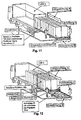
- FIG. 1 shows a schematic schematic diagram of a logistics system with a transfer station 20 according to a first embodiment of the present invention.
- the schematic outline of the FIG. 1 a view obliquely from above of a warehouse building in front of a truck 3 (see, eg FIG. 7 ) is to be positioned.
- the transfer station 20 of the first embodiment has a receptacle 21 which can accommodate two platforms 10a and 10b in the lifting direction C one above the other.
- a longitudinal feed unit 31 can be moved over the receptacle 21 in the longitudinal direction A in order to move one of the two platforms 10a and 10b or both stacked platforms 10a and 10b towards a truck 3 or away from a truck 3.
- the receptacle 21 itself can move in the direction B transversely to the longitudinal direction A, so as to be positioned and aligned with respect to the truck 3.
- the transfer station 20 also has a lifting unit 32, which can move in the lifting direction C vertically to the transfer station 20 level.
- a lifting unit 32 By means of this lifting unit 32, a platform 10 b can be raised so that it can be moved over the other platform 10 a over. This is necessary in order to be able to stack two platforms 10a and 10b, which are located at the same height in the receptacle 21 and on the loading area of the truck 3, one above the other.
- FIG. 2 shows a schematic schematic diagram of a logistics system with a transfer station 20 according to the first embodiment of the present invention in a view obliquely from above of a storage building.
- FIG. 3 shows a schematic schematic diagram of a logistics system with a transfer station 20 according to the first embodiment of the present invention in a plan view within a warehouse.
- the FIG. 3 shows a receptacle 21, in which no platforms 10a and 10b is present.
- FIG. 4 shows a schematic schematic diagram of a detailed view of the longitudinal feed unit 31 of the transfer station 20 according to the first embodiment of the present invention.
- FIG. 5 shows a schematic schematic diagram of a detailed view of the lifting unit 32 of the transfer station 20 according to the first embodiment of the present invention.
- the transfer station 20 is shown from outside a storage building.
- FIG. 6 shows a schematic schematic diagram of a detailed view of the transfer station 20 according to the first embodiment of the present invention.
- the transfer station 20 is shown from within a storage building.
- FIG. 7 shows a schematic schematic diagram of a first step of loading a truck 3 by means of a logistics system with a transfer station 20 according to the first embodiment of the present invention.
- a truck 3 is positioned and aligned in front of a docking station of a storage building opposite the transfer station 20 so that platforms 10a and 10b can be exchanged between the loading area of the truck 3 and the receptacle 21 of the transfer station.
- This is an unloaded platform 10a on the back of the truck 3 and a loaded platform 10b in the receptacle 21 of the transfer station 20.
- the longitudinal feed unit 31 is positioned at the height C of the loaded platform 10b on the inside of the warehouse building facing side of the loaded platform 10b, so that the longitudinal feed unit 31, the loaded Platform 10b can move from the receptacle 21 in the longitudinal direction A to the truck 3.
- the loading area of the truck 3 and the level of the transfer station 20 are at a height C, so that the two platforms 10a and 10b are on the truck 3 and in the receptacle 21 at the same height C.
- the first platform 10b has to be raised relative to the other platform 10a. This is done by the lifting unit 32 by the loading platform 10b is first pushed out of the receptacle 21 so far until the loaded platform 10b is above the lifting unit 32 during loading. Then, the lifting unit 32 lifts the loaded platform 10b so far that the loaded platform 10b can be pushed over the unloaded platform 10a in the truck 3, see FIG.
- the height C of the longitudinal feed unit 31 corresponds to the height C of the upper platform 10b.
- the loaded platform 10b is now pushed completely over the unloaded platform 10a on the back of the truck 3, see FIG. 9 , If both platforms 10a and 10b are completely stacked on top of each other, the longitudinal feed unit 31 is released from the upper, loaded platform 10b and the lifting unit 32 is lowered downwards. Now, the longitudinal feed unit 31 is lowered from the height C of the upper loaded platform 10b to the height C of the lower unloaded platform 10a and connected to the lower, unloaded platform 10a. Since the lower, unloaded platform 10a with the now empty receptacle 21 is at a height C, the two stacked platforms 10a and 10b can be pulled by the longitudinal feed unit 31 in the longitudinal direction A from the back of the truck 3 into the receptacle 21, see FIG. 3 , At the end of this pull-out movement are the two platforms 10a and 10b stacked one above the other completely in the receptacle 21 of the transfer station 20, see FIG. 11 ,
- the longitudinal feed unit 31 is released from the lower, unloaded platform 10a and raised to the height C of the upper, loaded platform 10b.
- the longitudinal feed unit 31 moves now the upper, loaded platform 10b in the longitudinal direction A on the back of the truck 3, see FIG. 12 .
- the lower, unloaded platform 10a is held in the receptacle 21 so as not to be moved from the upper, loaded platform 10b due to the feed movement with in the longitudinal direction A.
- the upper, loaded platform 10b is completely moved by the longitudinal feed unit 31 on the back of the truck 3, see FIG. 13 ,
- the height C of the longitudinal feed unit 31 is adapted to the height C of the upper, loaded platform 10b accordingly. This can prevent damage to the two platforms 10a and 10b, the truck 3 and its bed, as well as damage and slippage of the load on the upper loaded platform 10b.
- the longitudinal feed unit 31 is moved away from the loaded platform 10b to release the truck 3. *** " The loading process is completed and the loaded platform 10b may optionally be secured to the bed of the truck 3 before the truck 3 leaves its position in front of the docking station. Optionally, the height C of the longitudinal feed unit 31 is raised so that the longitudinal feed unit 31 can be moved over the unloaded platform 10 a. If required, the longitudinal feed unit 31 can then be moved again to the side of the transfer station 20 facing the bearing interior, see Figures 14 and 15 ,
- FIGS. 16 to 19 show a schematic schematic diagram of a transfer station 20 according to a second embodiment of the present invention.
- the transfer station 20 is designed to be mobile, ie the transfer station 20 can be taken as a whole by a forklift and moved.
- the transfer station 20 can receive an unloaded platform 10a or a loaded platform 10b in a receptacle 21 and move it in the transport direction B by means of two laterally provided transverse advance units 33.
- the transfer station 20 also has two fork openings 34, in which the forks of a forklift truck can intervene in order to grip, lift and move the transfer station 20.
- FIG. 16 a schematic schematic diagram of the transfer station 20 with a recorded in the receptacle 21 unloaded platform 10 a
- FIG. 17 a schematic diagram of the transfer station 20 with a receptacle 21 without platform 10a and 10b
- the FIG. 18 a schematic schematic diagram of the transfer station 20 with an approximately half of the receiving 21 moved unloaded platform 10a.
- the FIG. 19 shows a schematic schematic diagram of the transfer station 20 in a side view.
- an empty transfer station 20 picked up by a forklift truck is transported to an eg loaded platform 10b where it is raised or lowered to the height of the loaded platform 10b.
- the loaded platform 10b may be present on the floor of a storage building or in the receptacle 21 of a transfer station 20.
- the loaded platform 10b is moved by the transfer station 20 of the forklift on the receptacle 21.
- the forklift can drive to a truck 3, which has an empty loading area.
- the forklift is positioned and aligned adjacent to the bed of the truck 3 so that the loaded platform 10b can be slid vertically over the empty bed and the lateral dimensions of the loaded platform 10b to the dimensions of the empty bed of the truck 3 Cover can be brought.
- the loaded platform 10b is pushed by means of the transverse feed units 33 in the direction of transport B onto the empty loading area of the truck 3.
- the loading process is completed and the forklift can move away from the truck 3.
- the loaded platform 10b is to be secured.
- an unloaded platform 10a can be loaded on a truck 3 in the same way.
- An unloading operation in which an unloaded platform 10a or a loaded platform 10b is carried down from a truck 3 and transported away from the truck 3 by means of the forklift truck is carried out in the opposite order of the steps explained above.
- FIG. 20 shows a schematic view of a positioning system with a laser beam source 90, a first marker receptacle 91 and a second marker receptacle 92.
- This positioning system is suitable for easy and inexpensive alignment of the bed of the truck 3 and the receptacle 21 of the transfer station 20 to be used.
- the laser beam source 90 is mounted laterally on the back of the truck 3 to a corresponding receptacle that can be easily and inexpensively retrofitted on any truck 3, see FIG. 21 .
- it is crucial that the laser beam is emitted exactly in the direction of the longitudinal axis of the truck 3 away from it, that is exactly right angles to the back of the truck 3. Only with an exact alignment of the laser beam source Also an exact alignment between truck 3 and transfer station 20 by means of the laser beam of the laser beam source 90 possible.
- FIG. 22 1 shows a schematic representation of the first marking receptacle 91 of the positioning system, which is provided at the front area of the transfer station 20, ie at the area of the transfer station 20 facing the truck 3.
- the first marker receptacle 91 is formed as a Plexiglas plate
- the markings of the first marking receptacle 91 are horizontally and vertically extending lines, which are formed, for example, that only the areas of these line-shaped height and side markers are made transparent during the remaining Plexiglas plate is formed absorbent.
- the first marking receptacle 91 in the illustrated embodiment shows three horizontal height markers and a vertical side marker.
- the lower, middle and upper height markings of the first marker receptacle 91 are in the FIGS. 22 to 24 explicitly shown schematically.
- the Figures 25 and 26 show a schematic representation of the second marker receptacle 92, which is provided at the rear region of the transfer station 20, that is, on the truck 3 remote from the area of the transfer station 20.
- the second marker receptacle 92 is designed as an absorbing surface, so that the laser beam of the laser beam source 90 on the second marker receptacle 92 forms a laser spot, if the laser beam passes through one of the elevation markings and / or side marker of the first marker receptacle 91.
- the side mark of the first mark receiver 91 is designed to change the color of the laser beam.
- the laser spot on the second marker receptacle 92 it can be discriminated whether the laser beam passed through only one of the height marks - then the laser spot has the color of the laser beam in which the laser beam left the laser beam source 90 - or Whether the laser beam has passed through the side marker of the first marker retainer 91 at the same time or merely by the side marker - then the laser spot, when it encounters the second marker retainer 92, has a different color corresponding to the design of the side marker that it has passed through.
- the desired height may be the same height of the loading area of the truck 3 and the receptacle 21 of the transfer station 20.
- the desired height may also be the same height of the upper edge of a platform 10 and the loading area of the truck 3 or the receptacle 21 of the transfer station 20, if a platform 10 is to be transported via another platform 10. Therefore, the first marker receptacle 91 has a plurality of height markers, which are arranged one above the other by a multiple of the height of a platform 10.
- the transfer station 20 If the transfer station 20 is positioned by the operator at such a height that the laser beam passes through one of the height markings of the first marker receptacle 91, a laser spot is imaged on the second marker receptacle 92 as long as this height is maintained during the further process of the transfer station 20. At this height, the transfer station 20 can now be moved laterally until the color of the laser point changes. This indicates that the laser beam of the laser source 90 passes through the side mark of the first marker receptacle 91. Now, the transfer station 20 can be pivoted about its own vertical axis until the colored laser dot is imaged on the side marker of the second marker receptacle 92.
- the height of the transfer station 20 and the truck 3 are tuned to each other as desired to a multiple of the height of a platform 10, the transfer station 20 laterally aligned with the dimensions of the bed of the truck 3 and the longitudinal axes of the transfer station 20 and the truck 3 are in flight. Platforms 10 between the transfer station 20 and the truck 3 can now be exchanged without these platforms 10 jamming or jamming or abutting with the truck 3 or the transfer station 10.
- FIG. 27 shows a schematic representation of a preferred embodiment of a platform 10 of the logistics system according to the invention.
- the platform 10 recesses 84 for receiving a platform fuse 80 as already described above, see also FIG. 28
- lashing points 101a are provided on the lateral outer edges of the platform 10 in order to secure the cargo 11, for example by means of tension straps on the platform 10, see also FIG. 29
- the platform 10 of this embodiment also has two treads 100 on its upper side, which are made of metal, for example. In these treads 100 lashing points 101 a are also admitted to also to be able to secure cargo 11 at these points 101, see also FIG.
- treads 100 serve to allow the rollers 75 of another platform 10 to run on these surfaces 100 when a platform 10 is being conveyed over another platform 10.
- a defined, level and protected against damage and wear surface is provided for the rollers 75 of the upper platform 10 to avoid damage to and wear of the rollers of the upper platform or reduce and a smooth and energy-saving transport of the two To ensure platforms one above the other.
- FIG. 31 shows a schematic representation of the underside of a platform 10.
- this bottom wheel wells 70 are recessed, in which in turn wheels 75 and rollers 75 are provided.
- the platform 10 per wheel well 70 two wheels 75 are provided, which can be correspondingly smaller with a smaller diameter than when using only one wheel 75 per wheel arch 70.
- the weight of the platform 10 and thus the cargo 11th is significantly lower, so that when passing the Platform 10 between truck 3 and transfer station 20, the weight can be given even more uniform and there is no significant reduction in the truck 3 as in the use of fewer wheels 75th
- FIG. 32 shows a schematic representation of a transfer station 20 with lateral guides 110 on both sides of the receptacle 21.
- a detailed representation of one of the two lateral guides 110 is in FIG. 34 shown.
- the guides 110 on two superimposed guide rails 111.
- the lower guide rail 111 is provided at the level of the lower male platform 10 and the upper guide rail 111 is provided at the level of the upper male platform 10.
- both platforms to be recorded 10 can be guided laterally to be positioned exactly aligned and aligned in the receptacle 21 to be excluded.
- each platform 10 and especially the two superposed platforms 10 to be conveyed together are always aligned with the loading area of the truck 3. Since the dimensions of the platforms 10 are adapted to the dimensions of the loading surface of the truck 3, a very exact alignment of the platforms 10 crucial to properly perform the unloading and loading process with a platform 10 and especially with two superimposed platforms 10.
- FIG. 33 shows a schematic representation of a transfer station 20 with a lock 120.
- This lock 120 is provided to hold the lower platform 10 in the receptacle 21, ie to fix, if only the upper platform 10 moves from the receptacle 21 to the truck 3 out shall be.
- the lock 120 can press laterally against the sides of the platform 10 to clamp the platform 10 so.
- an engagement in the underside of the platform 10 can take place.
Description
Die Erfindung betrifft ein Verfahren zum Beladen von Fahrzeugen und ein Verfahren zum Entladen von Fahrzeugen und ein Logistiksystem sowie deren einzelne Teile hiervon, die zusammen das gesamte System bilden können, zum Beladen von Fahrzeugen und zum Entladen von Fahrzeugen.The invention relates to a method for loading vehicles and a method for unloading vehicles and a logistics system and their individual parts thereof, which together can form the entire system, for loading vehicles and for unloading vehicles.
Bei bereits vorhandenen Lagern oder Kommissionierungseinheiten gibt es eine Vielzahl von Andockstationen (auch als Hallentore bezeichnet), an die die LKWs jeweils mit ihrer Rückseite heranfahren können, um die Güter zu übernehmen. Solche Güterlager oder Kommissionierungseinheiten bestehen in einer großen Vielzahl und häufig gibt es die Möglichkeit, dass eine Vielzahl von Fahrzeugen gleichzeitig an die Andockstationen, die jeweils in einer Gebäudewand miteinander fluchtend nebeneinanderliegen, heranfährt. So können ebenso viele LKWs andocken, wie entsprechende Andockstationen, also Gebäudewandöffnungen/Hallentore, vorhanden sind. Dabei sind diese Andockstationen meist auf der Höhe der Ladeflächen der LKWs angeordnet, damit der Lagerboden und die Ladefläche des LKWs eine Ebene bilden und der LKW z.B. durch das Befahren durch Gabelstapler ent- und beladen werden kann. Da bei dieser Art des Ent- und Beladens jeder Gabelstapler oder sonstige Transporteinrichtung lediglich eine oder einige wenige Warenpalletten transportieren kann, ist die Art des Be- und Entladens sehr zeitintensiv. Auch kann der zu be- und entladende LKW während der gesamten Zeit des Be- und Entladens nicht von der Andockstation wegbewegt werden.In existing warehouses or picking units, there are a variety of docking stations (also referred to as hall gates), to which the trucks can approach each with their back to take over the goods. Such goods storage or picking units exist in a wide variety and often there is the possibility that a plurality of vehicles at the same time to the docking stations, which are juxtaposed in each case in a building wall next to each other, approaching. This means that as many trucks can dock as the corresponding docking stations, ie building wall openings / hall gates, are available. These docking stations are usually arranged at the height of the loading areas of the trucks, so that the storage floor and the loading area of the truck form a level and the truck can be unloaded and loaded eg by driving through forklifts. Since in this type of unloading and loading each forklift or other transport device can transport only one or a few product pallets, the type of loading and unloading is very time consuming. Also, the loading and unloading truck can not be moved away from the docking station during the entire time of loading and unloading.
Mit dem Logistiksystem des Dokuments
In den entsprechenden Lager- und Kommissionierungsbereichen des Logistiksystems des Dokuments
In der
In der
Das Logistiksystem des Dokuments
Die Aufgabe der vorliegenden Erfindung besteht darin, das Logistiksystem des Dokuments
Die Erfindung wird gelöst durch ein Verfahren zum Beladen von Fahrzeugen nach Anspruch 1, ein Verfahren zum Entladen von Fahrzeugen nach Anspruch 2 sowie einem Logistiksystem mit den Merkmalen nach Anspruch 3. Vorteilhafte Weiterbildungen sind in den Unteransprüchen, besonders aber auch in den Zeichnungen und in der nachfolgenden Beschreibung dargestellt.The invention is achieved by a method for loading vehicles according to claim 1, a method for unloading vehicles according to claim 2 and a logistics system having the features of
Es ist vorgesehen, das Logistiksystem des Dokuments
Auf diese Weise kann eine einzige Übergabestation eine unbeladene und eine beladene Plattform speichern, ohne dass hierfür wesentlich mehr Platz benötigt wird als für eine Plattform. Somit ist es gegenüber dem Logistiksystem des Dokuments
Dennoch bietet das erfindungsgemäße Logistiksystem die Vorteile des Logistiksystem des Dokuments
Erfindungsgemäß wird eine beladende Plattform im Lagergebäude unabhängig von der Präsenz des entsprechenden LKWs beladen, so dass eine beladene Plattform an der Übergabestation bereitstehen kann, wenn der zu beladende LKW das Lager erreicht und vor der entsprechenden Andockstation anhält. Die bereits beladene Plattform kann in nur einem Arbeitsschritt an den LKW abgegeben werden, indem die beladene Plattform auf die Ladefläche des unbeladenen LKWs verfahren wird. Befindet sich auf der Ladefläche des LKWs bereits eine unbeladene Plattform, so kann diese von derselben Übergabestation dadurch aufgenommen werden, dass die beladene Plattform von der Übergabestation über die unbeladene Plattform auf der Ladefläche des LKWs hinüber gefahren wird, dann beide Plattformen übereinandergestapelt wieder von der Ladefläche des LKWs auf die Übergabestation verfahren werden und schließlich lediglich die obere, beladene Plattform an den unbeladenen LKW abgegeben wird. Auch kann eine beladene Plattform aus einem anliefernden LKW durch die Übergabestation in einem einzigen Arbeitsschritt aufgenommen werden, wenn in der Übergabestation keine beladenen Plattform vorhanden ist, so dass die Plattform an der Übergabestation entladen werden kann, nachdem der LKW die entsprechende Andockstation bereits wieder verlassen hat. Dabei kann entsprechend den obigen Erläuterungen auch eine unbeladene Plattform an den anliefernden LKW abgegeben werden, indem ebenfalls die beladenen und die unbeladene Plattform übereinandergestapelt verfahren werden.According to the invention, a loading platform in the storage building is loaded independently of the presence of the corresponding truck, so that a loaded platform can be provided at the transfer station when the truck to be loaded reaches the warehouse and stops in front of the corresponding docking station. The already loaded platform can be delivered to the truck in just one step by moving the loaded platform onto the loading area of the unloaded truck. Located on the loading area the truck already has an unloaded platform, it can be picked up from the same transfer station by moving the loaded platform from the transfer station over the unloaded platform on the truck bed, then stacking both platforms back from the truck bed onto the transfer station Finally, only the upper, loaded platform is delivered to the unloaded truck. Also, a loaded platform can be picked up from a delivering truck by the transfer station in a single operation if there is no loaded platform in the transfer station so that the platform can be unloaded at the transfer station after the truck has already left the docking station , In this case, according to the above explanations, an unloaded platform can be delivered to the delivering truck by likewise moving the loaded and the unloaded platforms one above the other.
Das erfindungsgemäße Verfahren zum Beladen von Fahrzeugen zeichnet sich dabei dadurch aus, dass zunächst ein Fahrzeug mit einer unbeladenen Plattform vor einer Übergabestation so positioniert wird, dass Plattformen in Beförderungsrichtung von der Übergabestation zu dem Fahrzeug und bzw. oder von dem Fahrzeug zu der Übergabestation beförderbar sind. Dann wird eine beladene Plattform von der Übergabestation über die unbeladene Plattform des Fahrzeugs befördert. Als nächstes wird die unbeladene Plattform zusammen mit der beladenen Plattform von dem Fahrzeug zu der Übergabestation befördert. Schließlich wird die beladene Plattform zu dem Fahrzeug befördert und die unbeladene Plattform verbleibt in der Übergabestation.The method according to the invention for loading vehicles is characterized in that first a vehicle with an unloaded platform is positioned in front of a transfer station in such a way that platforms can be conveyed in the transport direction from the transfer station to the vehicle and / or from the vehicle to the transfer station , Then a loaded platform is carried from the transfer station over the unloaded platform of the vehicle. Next, the unloaded platform, along with the loaded platform, is conveyed from the vehicle to the transfer station. Finally, the loaded platform is conveyed to the vehicle and the unloaded platform remains in the transfer station.
Hierdurch kann in einem Vorgang eine beladene Plattform von einem LKW zu einer Übergabestation entladen und gleichzeitig eine unbeladene Plattform an den LKW abgegeben werden, ohne dass hierfür die Ladefläche des LKW betreten oder mit einem Gabelstapler befahren werden muss. Die Verwendung einer Plattform ermöglicht dabei, Waren auf der Plattform zu kommissionieren, ohne dass hierfür die Präsenz eines LKWs erforderlich ist. Hierdurch kann die Standzeit des LKW vor dem Lagergebäude deutlich reduziert und hierdurch Kosten gespart werden, da der LKW lediglich zur Aufnahme der vollständig kommissionierten Plattform vor dem Lagergebäude positioniert werden muss. Auch steigt die Flexibilität der gesamten Logistikkette durch die Verwendung des erfindungsgemäßen Logistiksystems erheblich, da nicht einzelne Waren auf die LKWs verladen werden, sondern lediglich eine Plattform auf die leere Ladefläche eines LKWs verschoben wird.As a result, in one process, a loaded platform can be unloaded from a truck to a transfer station and at the same time an unloaded platform can be delivered to the truck without having to enter the loading area of the truck or drive on it with a forklift truck. The use of a platform makes it possible to pick goods on the platform without requiring the presence of a truck. As a result, the service life of the truck can be significantly reduced in front of the warehouse and thus costs are saved, since the truck only needs to be positioned to accommodate the fully picked platform in front of the warehouse. Also, the flexibility of the entire logistics chain through the use of the logistics system according to the invention increases significantly, since not individual goods are loaded onto the trucks, but only a platform is moved to the empty loading area of a truck.
Das erfindungsgemäße Verfahren zum Beladen ermöglicht es ferner, eine beladene Plattform mit einer unbeladenen Plattform auszutauschen, ohne dass hierfür aufwendige Rangiervorgänge oder Abstellflächen zum Lagern einer Plattform erforderlich sind. Vielmehr kommt das erfindungsgemäße Verfahren im Wesentlichen mit dem Platz auf dem Boden des Lagergebäudes aus, der für eine Plattform erforderlich ist. So kann das erfindungsgemäße Verfahren platzsparend umgesetzt werden.The loading method according to the invention also makes it possible to exchange a loaded platform with an unloaded platform, without the need for complicated maneuvering operations or storage areas for storing a platform. Rather, the method according to the invention essentially takes place with the space on the floor of the storage building, which is required for a platform. Thus, the inventive method can be implemented to save space.
Ferner ist zu beachten, dass die Ladefläche eines LKWs lediglich von Hinten, von Oben oder von der Seite beladen werden kann. Dahingegen bietet das erfindungsgemäße Logistiksystem die Möglichkeit, die Plattform in der Aufnahme der Übergabestation gleichzeitig von beiden Seiten, von Oben und von Hinten zu beladen. Hierdurch wird das Kommissionieren der Plattform erheblich beschleunigt, da gleichzeitig mehrere Zugangsmöglichkeiten zu der Plattform vorhanden sind und so mehrere Personen, Gabelstapler oder auch Kräne und andere Transportvorrichtungen die Plattform beladen können. Ferner wird die Reihenfolge der Kommissionierung der einzelnen Waren nicht durch den Zugang zu der Ladefläche des LKWs vorgegeben, der z.B. lediglich von Hinten möglich ist, wodurch der Zugang zu im Inneren der Ladefläche des LKWs kommissionierten Waren durch die davorstehenden Waren versperrt wird, sondern es ist jederzeit ein Zugriff auf alle Waren möglich, um z.B. die Kommissionierung einer Plattform flexibel ändern zu können. Hierdurch ist es auch denkbar, dass eine Plattform in ein Lagergebäude angeliefert wird, lediglich ein Teil der Waren an einer beliebigen zugänglichen Position der Plattform entnommen, ausgetauscht oder ergänzt wird, und dann die Plattform wieder an den LKW oder einen anderen LKW übergeben wird. Hierdurch ermöglicht das erfindungsgemäße Logistiksystem eine weitaus größere Flexibilität als herkömmliche Logistiksysteme.It should also be noted that the loading area of a truck can only be loaded from the rear, from the top or from the side. On the other hand, the logistics system according to the invention offers the possibility of loading the platform in the receptacle of the transfer station simultaneously from both sides, from the top and from the rear. As a result, the picking of the platform is considerably accelerated, since at the same time several access to the platform are available and so can load several people, forklifts or cranes and other transport devices platform. Furthermore, the order of picking of the individual goods is not dictated by access to the bed of the truck, e.g. is only possible from the rear, whereby the access to goods picked in the interior of the truck bed of the truck is blocked by the goods in front, but it is at any time access to all goods possible, for. to flexibly change the picking of a platform. As a result, it is also conceivable that a platform is delivered to a warehouse, only a part of the goods is removed at any accessible position of the platform, replaced or supplemented, and then the platform is handed back to the truck or another truck. As a result, the logistics system according to the invention allows a much greater flexibility than conventional logistics systems.
Auch kann die Anordnung der Waren auf der Plattform überprüft und gesichert werden, bevor die Plattform auf den LKW verladen wird. Dies ist direkt auf der Ladefläche eines LKWs nicht bzw. nur eingeschränkt und aufwendig möglich, da nicht alle Waren frei einsehbar und zugänglich sind, wenn sie durch andere Waren verdeckt oder versperrt sind. Da die kommissionierte Plattform in der Übergabestation von allen Seiten frei zugänglich und einsehbar ist, kann hierdurch während des Kommissionierens sowie die vollständig kommissionierte Plattform jederzeit geprüft und gegebenenfalls gesichert werden, sodass durch das erfindungsgemäße Logistiksystem eine höhere Sicherheit der kommissionierten Waren als herkömmliche Logistiksysteme gewährleistet wird.Also, the order of goods on the platform can be checked and secured before the platform is loaded onto the truck. This is directly on the back of a truck not or only limited and expensive, since not all goods are freely visible and accessible, if they are covered or blocked by other goods. Since the picked platform in the transfer station is freely accessible and visible from all sides, this can be checked at any time during commissioning and the fully picked platform and secured if necessary, so that the logistics system according to the invention a higher security of goods picked than conventional logistics systems is guaranteed.
Das erfindungsgemäße Verfahren zum Entladen von Fahrzeugen zeichnet sich dabei dadurch aus, dass ein Fahrzeug mit einer unbeladenen Plattform vor einer Übergabestation so positioniert wird, dass Plattformen in Beförderungsrichtung von der Übergabestation zu dem Fahrzeug und bzw. oder von dem Fahrzeug zu der Übergabestation beförderbar sind. Dann wird eine beladene Plattform von dem Fahrzeug über die unbeladene Plattform der Übergabestation befördert. Als nächstes wird die unbeladene Plattform zusammen mit der beladenen Plattform von der Übergabestation zu dem Fahrzeug befördert. Schließlich wird die beladene Plattform zu der Übergabestation befördert und die unbeladene Plattform verbleibt in dem Fahrzeug.The method according to the invention for unloading vehicles is characterized in that a vehicle with an unloaded platform is positioned in front of a transfer station so that platforms can be conveyed in the direction of transport from the transfer station to the vehicle and / or from the vehicle to the transfer station. Then a loaded platform is carried by the vehicle via the unloaded platform of the transfer station. Next, the unloaded platform is carried along with the loaded platform from the transfer station to the vehicle. Finally, the loaded platform is conveyed to the transfer station and the unloaded platform remains in the vehicle.
Hierdurch kann in einem Vorgang eine beladene Plattform von einer Übergabestation zu einem LKW entladen und gleichzeitig eine unbeladene Plattform an die Übergabestation abgegeben werden. Für das Verfahren des Entladens eines Fahrzeugs gelten dabei die gleichen Vorteile des obigen Verfahrens des Beladens eines Fahrzeugs.As a result, in one process a loaded platform can be unloaded from a transfer station to a truck and at the same time an unloaded platform can be delivered to the transfer station. The same advantages of the above method of loading a vehicle apply to the method of unloading a vehicle.
Dabei zeichnen sich das Verfahren zum Beladen von Fahrzeugen und das Verfahren zum Entladen von Fahrzeugen dadurch aus, dass die Ausmaße der Plattform an denen der Ladefläche des Fahrzeugs angepasst sind.In this case, the method for loading vehicles and the method for unloading vehicles are characterized in that the dimensions of the platform are adapted to those of the loading area of the vehicle.
Hierdurch es möglich, den Raum der Ladefläche eines LKWs möglichst vollständig auszunutzen, da auf eine Plattform ebenso viele Waren kommissioniert werden können wie in dem Laderaum eines LKWs. Auf diese Weise können die oben genannten Vorteile des erfindungsgemäßen Logistiksystems erreicht werden, ohne hierdurch die Menge der zu transportierenden Waren einzuschränken.This makes it possible to use the space of the truck bed as completely as possible, because as many goods can be picked on a platform as in the hold of a truck. In this way, the above-mentioned advantages of the logistics system according to the invention can be achieved without thereby limiting the amount of goods to be transported.
Das erfindungsgemäße Logistiksystem betrifft die Übergabe einer Plattform in deren Beförderungsrichtung zu einem Fahrzeug und bzw. oder zur Übernahme einer Plattform von einem Fahrzeug. Dabei sind die Ausmaße der Plattform an denen der Ladefläche des Fahrzeugs angepasst. Das Logistiksystem weist eine Übergabestation für die Plattform auf, um die Plattform in Beförderungsrichtung von dem Fahrzeug zu übernehmen oder dorthin zu übergeben. Hierbei weist die Übergabestation eine Aufnahme auf, auf der die Plattform zur Anlage kommt und von der die Plattform in Beförderungsrichtung zu dem Fahrzeug und bzw. oder von dem Fahrzeug beförderbar ist. Ferner weist die Übergabestation eine Längsvorschubeinheit auf, um eine Plattform in Beförderungsrichtung zu bewegen. Das erfindungsgemäße Logistiksystem zeichnet sich dabei dadurch aus, dass die Längsvorschubeinheit dazu ausgebildet ist, zwei Plattformen vertikal übereinander aufzunehmen. Ferner ist die Längsvorschubeinheit dazu ausgebildet, wahlweise die zwei Plattformen in Beförderungsrichtung zu dem Fahrzeug und bzw. oder von dem Fahrzeug zu bewegen oder die obere Plattform über die untere Plattform in Beförderungsrichtung zu dem Fahrzeug und bzw. oder von dem Fahrzeug zu bewegen.The logistics system according to the invention relates to the transfer of a platform in its direction of transport to a vehicle and / or to take over a platform from a vehicle. The dimensions of the platform are adapted to those of the loading area of the vehicle. The logistics system has a transfer station for the platform to take over or transfer the platform in the direction of transport from the vehicle. In this case, the transfer station has a receptacle on which the platform comes to rest and from which the platform can be conveyed in the direction of transport to the vehicle and / or from the vehicle. Further, the transfer station has a longitudinal feed unit to move a platform in the conveying direction. The logistics system according to the invention is characterized in that the longitudinal feed unit is designed to vertically stack two platforms take. Further, the longitudinal feed unit is configured to selectively move the two platforms in the conveying direction to the vehicle and / or from the vehicle, or to move the upper platform via the lower platform in the conveying direction to the vehicle and / or from the vehicle.
Die Übergabestation des erfindungsgemäßen Logistiksystem kann zur Umsetzung des erfindungsgemäßen Verfahrens zum Beladen eines Fahrzeugs sowie des erfindungsgemäßen Verfahrens zum Entladen eines Fahrzeugs verwendet werden, um die oben genannten Vorteile dieser beiden Verfahren bereitzustellen. Dabei dient die Längsvorschubeinheit dazu, die Verfahrbewegungen in der Beförderungsrichtung der einzelnen Schritte des jeweiligen Verfahrens durchzuführen. Dies bedeutet, dass die Längsvorschubeinheit in der Lage ist, sowohl eine beladene Plattform, eine unbeladene Plattform als auch beide Plattformen übereinander gemeinsam sowohl vollständig in den LKW hineinzuschieben als auch vollständig aus dem LKW herauszuziehen. Hierzu ist es erforderlich, dass die Längsvorschubeinheit so verfahren werden kann, dass entweder die untere Plattform, alleine oder mit der darauf befindlichen oberen Plattform, oder lediglich die obere Plattform in den LKW geschoben oder aus dem LKW herausgezogen werden kann. Dabei kann die untere Plattform in der Aufnahme oder auf der Ladefläche des LKWs gehalten werden, um zu verhindert, dass bei einem Herausziehen oder Hineinschieben der oberen Plattform die untere Plattform mit bewegt wird.The transfer station of the logistics system according to the invention can be used to implement the method according to the invention for loading a vehicle and the method according to the invention for unloading a vehicle in order to provide the above-mentioned advantages of these two methods. In this case, the longitudinal feed unit serves to carry out the movement movements in the conveying direction of the individual steps of the respective method. This means that the longitudinal feed unit is capable of both a loaded platform, an unloaded platform as well as both platforms on top of each other both fully push into the truck as well as completely pull out of the truck. For this purpose, it is necessary that the longitudinal feed unit can be moved so that either the lower platform, alone or with the upper platform thereon, or only the upper platform can be pushed into the truck or pulled out of the truck. In this case, the lower platform can be held in the receptacle or on the bed of the truck in order to prevent that when pulling or pushing in of the upper platform, the lower platform is moved with.
Gemäß einem weiteren Aspekt des erfindungsgemäßen Logistiksystems zeichnet sich die Übergabestation dadurch aus, dass die Längsvorschubeinheit in der Höhe vertikal zu den Plattformen so verfahren werden kann, dass die Längsvorschubeinheit entweder auf die Höhe der oberen Plattform oder auf die Höhe der unteren Plattform verfahren werden kann.According to a further aspect of the logistics system according to the invention, the transfer station is characterized in that the longitudinal feed unit can be moved vertically in height to the platforms so that the longitudinal feed unit can be moved either to the height of the upper platform or to the height of the lower platform.
Hierzu wird die Höhe, in der die Längsvorschubeinheit sich bewegt, entsprechend dahingehend verstellt, sodass die Längsvorschubeinheit in einer unteren Höhe die untere Plattform schiebt oder zieht oder in einer oberen Höhe lediglich die obere Plattform schiebt oder zieht bzw. über die untere Plattform hinweg verfährt, ohne die untere Plattform zu schieben oder zu ziehen. Sind die beiden Plattformen übereinander gestapelt, so schiebt oder zieht die Längsvorschubeinheit in der unteren Höhe beide Plattformen.For this purpose, the height at which the longitudinal feed unit moves, adjusted accordingly so that the longitudinal feed unit pushes or pulls the lower platform in a lower level or pushes or pulls only the upper platform in an upper level or moves across the lower platform, without pushing or pulling the lower platform. If the two platforms stacked on top of each other, pushes or pulls the longitudinal feed unit in the lower level both platforms.
Gemäß einem weiteren Aspekt des erfindungsgemäßen Logistiksystems zeichnet sich die Übergabestation dadurch aus, dass die Übergabestation eine Hubeinheit aufweist, um eine Plattform oder zwei übereinandergestapelte Plattformen in Hubrichtung anzuheben.According to a further aspect of the logistics system according to the invention, the transfer station is characterized in that the transfer station has a lifting unit, to lift a platform or two stacked platforms in the stroke direction.
Hierdurch wird die Höhe, auf der die beladene oder unbeladene Plattform von der Aufnahme der Übergabestation über die unbeladene Plattform auf der Ladefläche des LKWs verfahren wird, eingestellt, da zwei Plattformen, die sich auf gleicher Höhe befinden, nicht übereinander gestapelt werden können, ohne eine der beiden Plattformen gegenüber der anderen anzuheben. Ferner kann die Hubeinheit dazu genutzt werden, die obere Plattform auf der Ladefläche des Fahrzeugs oder auf der Aufnahme anzulegen, nachdem die obere Plattform vollständig über die Maße der unteren Plattform hinweg befördert wurde.As a result, the height at which the loaded or unloaded platform is moved from receiving the transfer station via the unloaded platform on the bed of the truck, since two platforms, which are located at the same height, can not be stacked without one of the two platforms relative to the other. Further, the lift unit may be used to place the upper platform on the bed of the vehicle or on the seat after the upper deck has been fully extended beyond the dimensions of the lower deck.
Gemäß einem weiteren Aspekt des erfindungsgemäßen Logistiksystems zeichnet sich die Übergabestation dadurch aus, dass die Übergabestation in der Richtung quer zur Beförderungsrichtung verschiebbar ist.According to a further aspect of the logistics system according to the invention, the transfer station is characterized in that the transfer station is displaceable in the direction transverse to the transport direction.
Hierdurch kann die Übergabestation gegenüber einem vor dem Lagergebäude positionierten LKW ausgerichtet und verschoben werden, damit die Plattform, die an die Maße der Ladefläche des LKWs angepasst ist, von dem LKW übernommen oder an den LKW übergeben werden kann. Hierzu ist es erforderlich, dass die Positionierung und Ausrichtung von Übergabestation und Ladefläche des LKWs möglichst exakt aufeinander abgestimmt sind, um eine Verkanten der Plattform während des Ent- und Beladens zu vermeiden. Wird die Positionierung und Ausrichtung zueinander von der Übergabestation anstelle des LKWs übernommen, können aufwendige Rangiermanöver des LKWs vermieden und hierdurch Zeit gespart werden, da die Positionierung und Ausrichtung einfacher und schneller durch die Übergabestation durchgeführt werden kann als durch ein erneutes Verfahren und Positionieren des LKWs.In this way, the transfer station can be aligned with respect to a truck positioned in front of the warehouse and moved so that the platform, which is adapted to the dimensions of the bed of the truck, can be taken from the truck or handed over to the truck. For this purpose, it is necessary that the positioning and alignment of transfer station and loading area of the truck are matched as exactly as possible to avoid jamming of the platform during unloading and loading. If the positioning and alignment with one another are taken over by the transfer station instead of the truck, time-consuming maneuvering of the truck can be avoided and time can be saved since the positioning and alignment can be carried out more simply and more quickly by the transfer station than by a renewed movement and positioning of the truck.
Die vorliegende Erfindung betrifft ferner ein Logistiksystem zur Übergabe einer Plattform in deren Beförderungsrichtung zu einem Fahrzeug und bzw. oder zur Übernahme einer Plattform von einem Fahrzeug, dass sich dadurch auszeichnet, dass die Übergabestation von einem Gabelstapler aufgenommen werden kann.The present invention further relates to a logistics system for transferring a platform in its direction of transport to a vehicle and / or for taking over a platform from a vehicle, which is characterized in that the transfer station can be picked up by a forklift.
Hierdurch kann das erfindungsgemäße Logistiksystem auch angewendet werden auf LKW, die nicht vor einem Lagergebäude positioniert werden, weil entweder alle Andockstationen durch andere LKW belegt sind oder auch weil das erfindungsgemäße Logistiksystem lediglich in dieser mobilen Variante ausgeführt verwendet wird. Dabei können die oben genannten Vorteile des erfindungsgemäßen Logistiksystems auch in dieser Variante genutzt werden, da ebenfalls eine Kommissionierung der Plattform ohne die Präsenz eines LKWs im Lagergebäude möglich ist. Von dort wird eine kommissionierte Plattform von der Übergabestation des Gabelstaplers ebenso aufgenommen, wie diese in der oben beschriebenen Variante bei der Übergabe an den LKW direkt der Fall ist, d.h. der Gabelstapler positioniert die von ihm aufgenommene Übergabestation so zu der aufzunehmenden Plattform, dass diese von dem Kommissionierplatz des Lagergebäudes in die Aufnahme der Übergabestation des Gabelstaplers übernommen werden kann. Dann fährt der Gabelstapler zu dem LKW, der die beladene Plattform übernehmen soll. Dabei ist es erforderlich, dass die Ladefläche des LKWs keine Plattform aufweist, d. h. eine beladene oder unbeladene Plattform ist von dem LKW z.B. durch einen zweiten Gabelstapler mit Übergabestation bereits vorher zu entnehmen, oder es kann auch durch den Gabelstapler eine weitere Plattform auf eine bereits auf der Ladefläche des LKWs vorhandene unbeladene Plattform geschoben werden. Die beladene Plattform wird von der Übergabestation des Gabelstaplers auf die Ladefläche des LKWs abgegeben nachdem sich der Gabelstapler entsprechend zu dem LKW positioniert und ausgerichtet hat. Dabei wird im Allgemeinen das Aufnehmen und Übergeben der Plattform auf bzw. von der Übergabestation des Gabelstaplers in Richtung der Längsseite der Plattform und damit zur Seite des LKW quer zur Fahrtrichtung erfolgen, damit das Gewicht der Übergabestation mit der unbeladenen oder beladenen Plattform von dem Gabelstapler aufgenommen werden kann. Nichtsdestotrotz ist es auch möglich, die Übergabe und Übernahme der Plattformen in Längsrichtung des LKWs, d.h. in dessen Fahrtrichtung, durchzuführen, wenn die sich hierdurch ergebende Belastung von dem Gabelstapler aufgenommen werden kann.As a result, the logistics system according to the invention can also be applied to trucks that are not positioned in front of a warehouse because either all docking stations are occupied by other trucks or because the logistics system according to the invention is used only in this mobile variant. The can above-mentioned advantages of the logistics system according to the invention are also used in this variant, as well as a picking of the platform without the presence of a truck in the warehouse is possible. From there, an picked platform is taken up by the transfer station of the forklift as well, as in the variant described above in the transfer to the truck is directly the case, ie the forklift positioned by him transfer station so to the male platform, that of can be taken over the picking of the warehouse in the recording of the transfer station of the forklift. Then the forklift truck drives to the truck to take over the loaded platform. It is necessary that the bed of the truck has no platform, ie a loaded or unloaded platform can be seen from the truck, for example by a second forklift with transfer station before, or it can also by the forklift another platform on an already on the loading area of the truck existing unloaded platform are pushed. The loaded platform is delivered from the transfer station of the forklift to the back of the truck after the forklift has positioned and aligned with the truck. In general, picking and transferring the platform to and from the transfer station of the forklift will be in the direction of the longitudinal side of the platform and thus to the side of the truck transversely to the direction of travel so that the weight of the transfer station with the unloaded or loaded platform is picked up by the forklift can be. Nevertheless, it is also possible to carry out the transfer and takeover of the platforms in the longitudinal direction of the truck, ie in its direction of travel, if the resulting load can be absorbed by the forklift truck.
Gemäß einem weiteren Aspekt des erfindungsgemäßen Logistiksystems zeichnet sich die Übergabestation dadurch aus, dass die Übergabestation Gabelöffnungen aufweist, in die die Gabeln eines Gabelstaplers eingreifen können, um so die Übergabestation aufzunehmen.According to another aspect of the logistics system according to the invention, the transfer station is characterized in that the transfer station has fork openings, in which the forks of a forklift can intervene so as to receive the transfer station.
Durch diese Gabelöffnungen ist es möglich, eine einfache und kostengünstige Halterung an der Übergabestation vorzusehen, so dass diese von jedem beliebigen Gabelstapler aufgenommen werden kann, ohne konstruktive Veränderungen an dem Gabelstapler, insbesondere an den Gabeln des Gabelstaplers, vornehmen zu müssen. Hierdurch ist die Anwendbarkeit dieser Übergabestation durch übliche Gabelstapler gewährleitet.Through these fork openings, it is possible to provide a simple and inexpensive support to the transfer station, so that it can be picked up by any forklift, without having to make structural changes to the forklift, especially on the forks of the forklift. As a result, the applicability of this transfer station is ensured by conventional forklift.
Gemäß einem weiteren Aspekt des erfindungsgemäßen Logistiksystems zeichnet sich die Übergabestation dadurch aus, dass die Übergabestation an den beiden Seiten der Aufnahme in Beförderungsrichtung jeweils eine Vorschubeinheit aufweist, um die Plattform in Beförderungsrichtung zu dem Fahrzeug und bzw. oder von dem Fahrzeug zu bewegen.According to a further aspect of the logistics system according to the invention, the transfer station is characterized in that the transfer station on the two sides of the receptacle in the conveying direction each having a feed unit to move the platform in the direction of transport to the vehicle and / or from the vehicle.
Auf diese Weise ist es möglich, die Plattform von der Übergabestation abzugeben oder durch die Übergabestation aufzunehmen und dabei eine gleichförmige Vorschubkraft auf die Plattform auszuüben. Hierdurch kann ein Verkanten der Plattform in der Bewegung vermieden werden, da an beiden Seiten der Plattform gleichzeitig die gleichen Vorschubkräfte aufgebracht werden können. Ferner wird hierdurch mit einfachen Antriebsmitteln die Bewegung der Plattform ermöglicht werden, da jeweils bekannte und weit verbreitete Antriebe in üblicher Weise verwendet werden.In this way it is possible to deliver the platform from the transfer station or to receive it through the transfer station and thereby exert a uniform feed force on the platform. As a result, tilting of the platform in the movement can be avoided since the same feed forces can be applied to both sides of the platform at the same time. Furthermore, the movement of the platform is thereby made possible with simple drive means, since in each case known and widely used drives are used in the usual way.
Die vorliegende Erfindung betrifft ferner ein Logistiksystem zur Übergabe einer Plattform in deren Beförderungsrichtung zu einem Fahrzeug und bzw. oder zur Übernahme einer Plattform von einem Fahrzeug, wobei das Logistiksystem eine Übergabestation mit einer Aufnahme für mindestens eine Plattform aufweist, um eine Plattform in Beförderungsrichtung von dem Fahrzeug zu übernehmen oder dorthin zu übergeben. Dabei weist das Fahrzeug eine Laserstrahlquelle auf. Ferner weist die Übergabestation eine erste Markierungsaufnahme und eine zweite Markierungsaufnahme auf, wobei die erste Markierungsaufnahme derart ausgestaltet ist, dass der Laserstrahl der Laserstrahlquelle durch die erste Markierungsaufnahme hindurchtritt und auf die zweite Markierungsaufnahme auftrifft.The present invention further relates to a logistics system for transferring a platform in its direction of transport to a vehicle and / or for taking over a platform from a vehicle, wherein the logistics system has a transfer station with a receptacle for at least one platform to a platform in the transport direction of the Vehicle to take over or transfer there. In this case, the vehicle has a laser beam source. Furthermore, the transfer station has a first marker receptacle and a second marker receptacle, wherein the first marker receptacle is configured such that the laser beam of the laser beam source passes through the first marker receptacle and impinges on the second marker receptacle.
Gemäß einem weiteren Aspekt des erfindungsgemäßen Logistiksystems ist die Laserstrahlquelle an Rückseite oder Seitenfläche der Ladefläche des Fahrzeugs derart vorgesehen ist, dass der Laserstrahl der Laserstrahlquelle rechtwinklig zur Rückseite der Ladefläche des Fahrzeugs abgegeben wird. Hierdurch wird sichergestellt, dass der Laserstrahl zur Ausrichtung von Fahrzeugladefläche und Übergabestation in der Höhe, seitlich und Winkellage zueinander geeignet ist, um eine Übergabe von Plattformen zwischen Fahrzeug und Übergabestation zu ermöglichen. Da die Maße der Plattform den Maßen der Ladefläche des Fahrzeugs entsprechen, ist gerade eine möglichst exakte Ausrichtung um die Hochachse der Übergabestation von großer Bedeutung, da es sonst zu einem Verklemmen der Plattform während des Übergabevorgangs kommen kann.According to a further aspect of the logistics system according to the invention, the laser beam source is provided on the rear side or side surface of the loading area of the vehicle such that the laser beam of the laser beam source is emitted at right angles to the rear side of the loading area of the vehicle. This ensures that the laser beam is suitable for aligning the vehicle loading surface and the transfer station in height, laterally and angular position with respect to one another, in order to enable the transfer of platforms between the vehicle and the transfer station. Since the dimensions of the platform correspond to the dimensions of the loading area of the vehicle, it is precisely an alignment that is as exact as possible about the vertical axis of the transfer station that is of great importance since otherwise the platform could become jammed during the transfer process.
Gemäß einem weiteren Aspekt des erfindungsgemäßen Logistiksystems weist die erste Markierungsaufnahme in horizontaler Richtung mehrere Höhenmarkierungen und in vertikaler Richtung mindestens eine Seitenmarkierung auf, die für den Laserstrahl der Laserstrahlquelle durchlässig sind, und die zweite Markierungsaufnahme ist für den Laserstrahl der Laserstrahlquelle undurchlässig.According to a further aspect of the logistics system according to the invention, the first marking receptacle has several height markings in the horizontal direction and at least one side mark permeable to the laser beam of the laser beam source in the vertical direction, and the second mark receptacle is impermeable to the laser beam of the laser beam source.
Durch diese Anordnung von Laserstrahlquelle, erster und zweiter Markierungsaufnahme wird eine genaue Ausrichtung zwischen der Ladefläche des Fahrzeugs und der Aufnahme der Übergabestation auf einfache und kostengünstige Art und Weise ermöglicht. Dabei ist die Laserquelle an einer definierten Position hinsichtlich ihrer Höhe gegenüber der Ladefläche des Fahrzeugs sowie ihrer seitlichen Positionierung vorzusehen. Wird nun ein mit einer derartigen Laserquelle versehenes Fahrzeug rückwärts an eine Übergabestation herangefahren und grob positioniert und ausgerichtet vor der Übergabestation abgestellt, so kann nun die Feinpositionierung und -ausrichtung der Übergabestation gegenüber dem Fahrzeug mittels der beiden Markierungsaufnahmen der Übergabestation erfolgen. Um diese Positionierung und Ausrichtung vorzunehmen, sind entsprechende Antriebe und Führungen an der Übergabestation vorzusehen, die zumindest ein seitliches Verschieben der Übergabestation gegenüber dem Fahrzeug, eine Veränderung der Höhe der Aufnahme der Übergabestation sowie ein Schwenken der Übergabestation um ihre Hochachse ermöglichen. Dabei wird nun erfindungsgemäß der Laserstrahl auf die erste Markierungsaufnahme treffen. Die erste Markierungsaufnahme ist bis auf einige Markierungen undurchsichtig ausgebildet, sodass der Laserstrahl von der ersten Markierungsaufnahme absorbiert wird und dort einen Laserpunkt ausbildet - auf der zweiten Markierungsaufnahme ist kein Laserpunkt zu sehen. Nun kann die Übergabestation in der Höhe und zur Seite so verfahren werden, dass der Laserstrahl durch eine der Höhenmarkierung und die Seitenmarkierung der ersten Markierungsaufnahme hindurchtritt und auf der zweiten Markierungsaufnahme einen Laserpunkt ausbildet. Hierdurch kann die Übergabestation auf einfache Art und Weise in der Höhe ausgerichtet werden, da die verschiedenen Höhenmarkierungen der ersten Markierungsaufnahme verschiedene Höhen der Übergabestation gegenüber dem Fahrzeug markieren.This arrangement of the laser beam source, first and second marker recording a precise alignment between the loading area of the vehicle and the recording of the transfer station in a simple and inexpensive way possible. In this case, the laser source is to be provided at a defined position with respect to its height relative to the loading area of the vehicle and its lateral positioning. If now a vehicle provided with such a laser source is moved backwards to a transfer station and roughly positioned and parked in front of the transfer station, the fine positioning and alignment of the transfer station with respect to the vehicle can now take place by means of the two marking receptacles of the transfer station. To make this positioning and alignment, appropriate drives and guides are provided at the transfer station, which allow at least a lateral displacement of the transfer station relative to the vehicle, a change in the height of the receiving station and a pivoting of the transfer station about its vertical axis. In this case, according to the invention, the laser beam will strike the first marking receptacle. The first marker receptacle is opaque except for a few markings, so that the laser beam is absorbed by the first marker receptacle and forms a laser spot there - on the second marker shot no laser spot can be seen. Now, the transfer station can be moved in height and to the side so that the laser beam passes through one of the height marking and the side marker of the first marker recording and forms a laser spot on the second marker recording. In this way, the transfer station can be aligned in a simple manner in height, since the different height marks of the first marker recording mark different heights of the transfer station relative to the vehicle.
Gemäß einem weiteren Aspekt des erfindungsgemäßen Logistiksystems tritt der Laserstrahl der Laserstrahlquelle, wenn er durch eine der Höhenmarkierungen und bzw. oder eine Seitenmarkierung der ersten Markierungsaufnahme hindurchtritt, auf die zweite Markierungsaufnahme auf und bildet dort einen Laserpunkt ab. Ferner wird der Laserstrahl der Laserstrahlquelle, wenn er auf die erste Markierungsaufnahme auftritt ohne durch eine der Höhenmarkierungen und bzw. oder eine Seitenmarkierung der ersten Markierungsaufnahme hindurchzutreten, von der erste Markierungsaufnahme vollständig absorbiert. Hierdurch wird erreicht, daß auf der zweiten Markierungsaufnahme klar und deutlich unterschieden werden kann, ob der Laserstrahl durch eine der Höhen- und bzw. oder Seitenmarkierungen der ersten Markierungsaufnahme hindurchtritt oder nicht. Da die Ausrichtung der Übergabestation gegenüber dem Fahrzeug aufgrund dieses Laserstrahls erfolgt, ist es wichtig, dass dieser Laserstrahl bzw. der Laserpunkt, der auf der zweiten Markierungsaufnahme von dem Laserstrahl ausgebildet wird, klar und eindeutig vom Bediener, der den Ausrichtevorgang durchführt, wahrgenommen werden kann.According to a further aspect of the logistics system according to the invention, the laser beam of the laser beam source, when it passes through one of the height markings and / or a side marker of the first marker shot, occurs on the second marker shot and forms a laser spot there. Further, the laser beam of the laser beam source when it occurs on the first marker recording without pass through one of the elevation marks and / or a side mark of the first mark receiver, completely absorbed by the first marker shot. This ensures that it can be clearly and clearly distinguished on the second marker recording, whether the laser beam passes through one of the elevation and or or side markings of the first marker recording or not. Since the alignment of the transfer station with respect to the vehicle is due to this laser beam, it is important that this laser beam or the laser spot formed on the second marker mount of the laser beam can be clearly and clearly perceived by the operator performing the alignment operation ,
Gemäß einem weiteren Aspekt des erfindungsgemäßen Logistiksystems weist die erste Markierungsaufnahme in horizontaler Richtung drei Höhenmarkierungen auf, und der Abstand zwischen der unteren und der mittleren Höhenmarkierung sowie der Abstand zwischen der mittleren und der oberen Höhenmarkierung entspricht der Höhe einer Plattform. Dieser Abstand zwischen den Höhenmarkierungen der ersten Markierungsaufnahme trägt dem Umstand Rechnung, dass auf der Ladefläche des Fahrzeugs und in der Aufnahme der Übergabestation eine oder mehrere Plattformen übereinander angeordnet werden können, die einzeln oder mehrere übereinander zwischen Fahrzeug und Übergabestation übergeben werden. Da der Abstand der Höhenmarkierungen der Höhe dieser Plattformen entspricht, kann auch der Abstand zwischen Ladefläche des Fahrzeugs und Aufnahme der Übergabestation auf ein ganzzahliges vielfaches der Plattformhöhe eingestellt werden.According to a further aspect of the logistics system according to the invention, the first marking receptacle has three height markings in the horizontal direction, and the distance between the lower and the middle height marking and the distance between the middle and the upper height marking corresponds to the height of a platform. This distance between the height markings of the first marker recording takes into account the fact that one or more platforms can be stacked on the loading area of the vehicle and in the receptacle of the transfer station, which are transferred individually or more one above the other between the vehicle and transfer station. Since the distance of the height marks corresponds to the height of these platforms, the distance between the loading area of the vehicle and the reception of the transfer station can also be set to an integer multiple of the platform height.
Gemäß einem weiteren Aspekt des erfindungsgemäßen Logistiksystems trifft der Laserstrahl der Laserstrahlquelle dann durch die mittlere Höhenmarkierung der ersten Markierungsaufnahme auf die zweite Markierungsaufnahme auf und bildet dort einen Laserpunkt ab, wenn sich die Ladefläche des Fahrzeugs und die Aufnahme der Übergabestation auf der gleichen Höhe befinden. Hierdurch wird eine Ausrichtung in der Höhe von Ladefläche des Fahrzeugs und Aufnahme der Übergabestation zueinander für den Fall auf einfache Art und Weise ermöglicht, dass eine Plattform zwischen Fahrzeug und Übergabestation übergeben werden soll, da jeweils eine weitere Markierung oberhalb und unterhalb der mittleren Markierung vorhanden ist, die um die Höhe einer Plattform von der mittleren Markierung verschoben ist.According to a further aspect of the logistics system according to the invention, the laser beam source then impinges on the second marker receptacle through the middle elevation marking of the first marker receptacle and forms a laser spot there when the loading area of the vehicle and the receptacle of the transfer station are at the same height. As a result, an alignment in the height of the loading area of the vehicle and reception of the transfer station to each other in a simple manner allows the case to be transferred between the vehicle and transfer station, since in each case a further mark above and below the middle mark is present , which is offset by the height of a platform from the middle mark.
Gemäß einem weiteren Aspekt des erfindungsgemäßen Logistiksystems weist die erste Markierungsaufnahme eine Seitenmarkierung und die zweite Markierungsaufnahme eine Seitenmarkierung auf. Dabei trifft der Laserstrahl der Laserstrahlquelle dann durch die Seitenmarkierung der ersten Markierungsaufnahme auf die Seitenmarkierung der zweiten Markierungsaufnahme auf und bildet dort einen Laserpunkt ab, wenn das Fahrzeug in der Flucht mit der Übergabestation ausgerichtet ist. Durch diese beiden Seitenmarkierungen, die mittels des Laserstrahls in Deckung zueinander zu bringen sind, um die Ladefläche des Fahrzeugs und die Aufnahme der Übergabestation in Verlängerung zueinander auszurichten, wird auf einfache Art und Weise die Ausrichtung mittels "Kimme und Korn" umgesetzt. So liegen nur dann Laserstrahlquelle an der Rückseite des Fahrzeugs, erste Seitenmarkierung der ersten Markierungsaufnahme und zweite Seitenmarkierung der zweiten Markierungsaufnahme in einer Linie zueinander, was an der Abbildung des Laserpunktes auf der Seitenmarkierung der zweiten Markierungsaufnahme leicht nachzuvollziehen ist, wenn die Ladefläche des Fahrzeugs und die Aufnahme der Übergabestation zueinander in Flucht ausgerichtet sind.According to a further aspect of the logistics system according to the invention, the first marking receptacle has a side marking and the second marking receptacle Side marker on. In this case, the laser beam of the laser beam source then impinges on the side marker of the second marker receptacle through the side marker of the first marker receptacle and forms a laser spot there when the vehicle is aligned in alignment with the transfer station. By these two side markings, which are to bring by means of the laser beam to each other to align the loading area of the vehicle and the recording of the transfer station in extension to each other, the alignment by means of "sight and grain" is implemented in a simple manner. Thus, only laser beam source at the rear of the vehicle, first side marker of the first marker recording and second side marker of the second marker recording in a line to each other, which is easy to understand the image of the laser spot on the side marker of the second marker recording when the back of the vehicle and the Recording the transfer station aligned with each other in flight.
Gemäß einem weiteren Aspekt des erfindungsgemäßen Logistiksystems ist eine Seitenmarkierung der ersten Markierungsaufnahme derart ausgebildet, die Farbe des Laserstrahl der Laserstrahlquelle so zu verändern, dass der Laserpunkt, der von dem Laserstrahl der Laserstrahlquelle auf der zweiten Markierungsaufnahme ausgebildet wird, durch seine Farbe anzeigt, ob er durch eine Seitenmarkierung der ersten Markierungsaufnahme hindurchgetreten ist oder nicht. Durch diese farbige Kennzeichnung der Laserstrahl kann auf der zweiten Markierungsaufnahme einfach erkannt werden, ob der Laserstrahl durch eine der durchlässigen Höhenmarkierungen der ersten Markierungsaufnahme hindurchtritt oder ob der Laserstrahl durch eine Seitenmarkierung der ersten Markierungsaufnahme hindurchtritt. Hierdurch ist eine Unterscheidung dieser Markierungen durch die Farbe des Laserpunktes auf der zweiten Markierungsaufnahme auf einfache und sichere Art und Weise möglich.According to a further aspect of the logistics system according to the invention, a side marker of the first marker receptacle is designed to change the color of the laser beam of the laser beam source so that the laser spot formed by the laser beam of the laser beam source on the second marker receptacle indicates by its color whether it is has passed through a side marker of the first marker receptacle or not. This colored marking of the laser beam makes it easy to detect on the second marking receptacle whether the laser beam passes through one of the permeable height markings of the first marking receptacle or whether the laser beam passes through a side marking of the first marking receptacle. This makes it possible to distinguish these markings by the color of the laser spot on the second marker recording in a simple and secure manner.
Die vorliegende Erfindung betrifft ferner ein Logistiksystem zur Übergabe einer Plattform in deren Beförderungsrichtung zu einem Fahrzeug und bzw. oder zur Übernahme einer Plattform von einem Fahrzeug, wobei das Logistiksystem eine Übergabestation mit einer Aufnahme für mindestens eine Plattform aufweist, um eine Plattform in Beförderungsrichtung von dem Fahrzeug zu übernehmen oder dorthin zu übergeben. Die Plattform weist auf ihrer Oberseite mehrere Laufflächen und an ihrer Unterseite mehrere Räder auf, wobei die Laufflächen und die Räder derart übereinander angeordnet sind, dass die Räder einer Plattform auf den Laufflächen einer anderen Plattform laufen, wenn die eine Plattform über die andere Plattform befördert wird. Hierdurch ist die Plattform derart ausgebildet, dass Beschädigungen und Abnutzungen der Oberfläche der Plattform, auf der die zu befördernde Fracht kommissioniert wird, dahingehend vermieden bzw. zumindest reduziert wird, dass die Oberfläche der Plattform nicht durch die Laufrollen bzw. Räder einer weiteren Plattform beschädigt oder abgenutzt wird, wenn zwei Plattformen übereinander befördert werden. Die Oberfläche einer Plattform wird im Allgemeinen vollständig aus einem Material wie z.B. Holz gefertigt. Wird nun eine Plattform über eine weitere Plattform befördert, kann es auf der hölzernen Oberfläche der unteren Plattform durch die Räder bzw. Laufrollen der oberen Plattform zu Abrieb kommen, sowohl der hölzernen Oberfläche als auch der Laufrollen, welche im Allgemeinen aus einem Material wie Kunststoff oder Gummi gefertigt werden. Hierdurch kommt es zu Verschleiß an der Oberfläche sowie an den Laufrollen, welche entsprechend erneuert werden müssen. Auch kann sich aufgrund des Verschleißes der Kraftaufwand für die Bewegung der Plattformen erhöhen. Ferner kann auch die hölzerne Oberfläche der Plattform durch das Kommissionieren durch z.B. einen Gabelstapler oder ähnliche Geräte beschädigt oder abgenutzt werden, so dass in dem Bereich, über den die Laufrollen einer anderen Plattform laufen, Holzteile ausbrechen können und Vertiefungen bilden oder auch Holzteile nach Oben hervorstehen und hierdurch Hindernisse darstellen. In beiden Fällen wird durch die Unebenheit der hölzernen Oberfläche die Bewegung einer Plattform über eine andere erschwert. Daher ist es vorteilhaft, diesen Bereich der Plattformen, über den die Laufrollen einer anderen Plattformen laufen, aus einem Material vorzusehen, dass weniger beschädigt werden kann und sich weniger abnutzt, um den Verschleiß der Laufflächen und Laufrollen zu verringern und sicherzustellen, dass durch die Abnutzung oder Beschädigung der Oberfläche der Plattform keine Behinderungen der Beförderungsbewegung entsteht.The present invention further relates to a logistics system for transferring a platform in its direction of transport to a vehicle and / or for taking over a platform from a vehicle, wherein the logistics system has a transfer station with a receptacle for at least one platform to a platform in the transport direction of the Vehicle to take over or transfer there. The platform has a plurality of treads on the upper side thereof and a plurality of wheels on the lower side thereof, the treads and the wheels being stacked so that the wheels of one platform run on the treads of another platform as the one platform is conveyed over the other platform , As a result, the platform is like this designed such that damage and wear of the surface of the platform on which the cargo to be transported is picked, is avoided or at least reduced so that the surface of the platform is not damaged or worn by the rollers of another platform, if two Platforms are transported one above the other. The surface of a platform is generally made entirely of a material such as wood. Now, when a platform is conveyed over another platform, it may be abraded on the wooden surface of the lower platform by the wheels or rollers of the upper platform, both the wooden surface and the rollers, which are generally made of a material such as plastic or plastic Rubber are made. This causes wear on the surface and on the rollers, which must be renewed accordingly. Also, due to wear, the force required to move the platforms may increase. Furthermore, the wooden surface of the platform can be damaged or worn by picking by eg a forklift or similar devices, so that in the area over which run the rollers of another platform, wood parts can break out and form depressions or wood parts projecting upwards and thus obstacles. In both cases, the unevenness of the wooden surface makes the movement of one platform over another more difficult. Therefore, it is advantageous to provide that portion of the platforms over which the rollers of other platforms pass, of a material that can be less damaged and less worn to reduce wear of the treads and rollers and to ensure wear or damage to the surface of the platform does not interfere with the carriage movement.
Gemäß einem weiteren Aspekt des erfindungsgemäßen Logistiksystems sind an den seitlichen Außenkanten der Plattform Zurrpunkte zum Sichern der Fracht vorgesehen. Ferner sind zusätzlich oder alternativ in den Laufflächen Zurrpunkte zum Sichern der Fracht vorgesehen. Auch sind zusätzlich oder alternativ an den Stirnkanten der Plattform Aussparungen zur Aufnahme einer Plattformsicherung vorgesehen. Durch diese Zurrpunkte können an der Plattform Befestigungsmittel auf platzsparende Art und Weise angebracht werden, um die Fracht in Beförderungsrichtung und in Querrichtung durch z.B. Spanngurte zu sichern. Ferner dienen die Aussparungen der Sicherung der Plattform auf der Ladefläche des Fahrzeugs.According to another aspect of the logistics system according to the invention lashing points for securing the cargo are provided on the lateral outer edges of the platform. Furthermore, lashing points for securing the freight are additionally or alternatively provided in the running surfaces. Also, in addition or alternatively, recesses for receiving a platform securing are provided on the front edges of the platform. By means of these lashing points, fastening means can be attached to the platform in a space-saving manner, in order to secure the freight in the conveying direction and in the transverse direction, for example by means of straps. Furthermore, the recesses serve to secure the platform on the loading area of the vehicle.
Gemäß einem weiteren Aspekt des erfindungsgemäßen Logistiksystems sind die Räder in entsprechenden Radkästen auf der Unterseite der Plattform in die Plattform eingelassen vorgesehen, und pro Radkasten sind zwei Räder vorgesehen, die in Beförderungsrichtung nebeneinander angeordnet sind. Dadurch, dass zwei Räder statt lediglich einem Rad pro Radkasten vorgesehen sind, kann der Durchmesser jedes Rades bzw. jeder Laufrolle weiter verringert werden, so dass die Höhe der Plattform, die im Wesentlichen durch den Durchmesser der Räder bzw. Laufrollen bestimmt wird, ebenfalls entsprechend verringert werden kann und dennoch die gleiche Last von der Gesamtheit der Räder aufgenommen werden kann. Ferner können hierdurch mehr Räder bzw. Laufrollen an der Unterseite der Plattform vorgesehen werden, die entsprechend einen geringeren Abstand zueinander aufweisen. Hierdurch liegen auch die Kontaktpunkte der Plattform mit dem Untergrund, also die Kontaktpunkte der Räder bzw. Laufrollen, dichter bei einander, so dass bei der Übergabe von der Aufnahme der Übergabestation zur Ladefläche des Fahrzeugs schneller die Gewichtskraft der Plattform und Fracht durch mehrere Räder übergeben wird. Hierdurch wird die Belastung für die einzelnen Räder bzw. Laufrollen reduziert.According to a further aspect of the logistics system according to the invention, the wheels are provided in corresponding wheel arches on the underside of the platform embedded in the platform, and per wheel well two wheels are provided, which are arranged side by side in the conveying direction. By providing two wheels instead of just one wheel per wheel well, the diameter of each wheel or roller can be further reduced, so that the height of the platform, which is essentially determined by the diameter of the wheels or rollers, also correspondingly can be reduced and yet the same load can be absorbed by the totality of the wheels. Furthermore, more wheels or rollers can be provided on the underside of the platform, which accordingly have a smaller distance from each other. As a result, the contact points of the platform with the ground, so the contact points of the wheels or rollers, closer to each other, so that when transferring the recording of the transfer station to the loading area of the vehicle faster the weight of the platform and cargo is passed through several wheels , As a result, the burden on the individual wheels or rollers is reduced.
Die vorliegende Erfindung betrifft ferner ein Logistiksystem zur Übergabe einer Plattform in deren Beförderungsrichtung zu einem Fahrzeug und bzw. oder zur Übernahme einer Plattform von einem Fahrzeug, wobei das Logistiksystem eine Übergabestation mit einer Aufnahme für mindestens eine Plattform aufweist, um eine Plattform in Beförderungsrichtung von dem Fahrzeug zu übernehmen oder dorthin zu übergeben. Dabei weist die Übergabestation an beiden Seiten der Aufnahme Führungen auf, und bzw. oder die Übergabestation weist eine Arretierung zum Arretieren einer in der Aufnahme befindlichen Plattform auf.The present invention further relates to a logistics system for transferring a platform in its direction of transport to a vehicle and / or for taking over a platform from a vehicle, wherein the logistics system has a transfer station with a receptacle for at least one platform to a platform in the transport direction of the Vehicle to take over or transfer there. In this case, the transfer station has guides on both sides of the receptacle, and / or the transfer station has a lock for locking a platform located in the receptacle.
Mittels einer derart ausgestalteten Übergabestation kann die eine Plattform oder auch die mehreren Plattformen, die von dem Fahrzeug an die Übergabestation übergeben werden, seitlich geführt werden, um sicher zu stellen, dass die eine Plattform oder auch die mehreren Plattformen genau positioniert und ausgerichtet in der Aufnahme aufgenommen werden, um die Plattform oder die Plattformen auch wieder von der Aufnahme zu dem Fahrzeug übergeben zu können, ohne dass sich die Plattformen in der Aufnahme oder der Ladefläche des Fahrzeugs verkanten, verklemmen oder an die Seiten der Ladefläche des Fahrzeugs anstoßen. Hierdurch kann ein fehlerfreier und damit zügiger Umladevorgang einer oder mehrere Plattformen gewährleistet werden.By means of a transfer station configured in this way, the one or more platforms transferred from the vehicle to the transfer station can be guided laterally to ensure that the one or more platforms are accurately positioned and aligned in the receptacle be taken to the platform or the platforms again from the receptacle to the vehicle to be able to pass, without tilting the platforms in the receptacle or the loading area of the vehicle, jam or abut the sides of the bed of the vehicle. As a result, an error-free and thus rapid reloading of one or more platforms can be ensured.
Gemäß einem weiteren Aspekt des erfindungsgemäßen Logistiksystems weisen die Führungen der Aufnahme Führungsleisten auf, und die Führungsleisten sind aus Kunststoff oder Hartplastik ausgebildet. Hierdurch wird vermieden, dass Metall, z.B. der Rahmen der Plattform, auf Metall, z.B. die Führungen, auftrifft, sondern der Rahmen der Plattform wird gegen ein weiches Material geführt, sodass kein metallischer Abrieb oder Beschädigungen des Rahmens der Plattform entstehen. Durch den Kunststoff oder das Hartplastik, welches beides weit verbreitete Materialien zur reibungsarmen Führung von beweglichen Bauteilen gegeneinander sind, wird eine sichere und reibungsarme Führung der Plattform in der Aufnahme sichergestellt.According to another aspect of the logistics system according to the invention, the guides of the recording on guide rails, and the guide rails are made of plastic or hard plastic. This avoids that metal, e.g. the frame of the platform, on metal, e.g. the guides, but the frame of the platform is guided against a soft material, so that no metallic abrasion or damage to the frame of the platform arise. Due to the plastic or hard plastic, which are both widely used materials for low-friction guidance of moving components against each other, a secure and low-friction guidance of the platform is ensured in the recording.
Gemäß einem weiteren Aspekt des erfindungsgemäßen Logistiksystems ist die Arretierung der Aufnahme derart ausgebildet, die untere Plattform in der Aufnahme zu arretieren, falls mehrere Plattformen übereinander mittels der Übergabestation befördert werden. Die Arretierung der Übergabestation sorgt hierdurch dafür, dass die untere Plattform in der Aufnahme verbleibt und sich nicht aus der Aufnahme zu dem Fahrzeug hin mit bewegt, falls mehrere Plattformen übereinander in der Aufnahme vorhanden sind und lediglich die obere Plattform, d.h. alle Plattformen außer der unteren, aus der Aufnahme zu dem Fahrzeug hin befördert werden soll. Hierdurch kann ein zuverlässiger Austausch von mehrere Plattformen mittels lediglich einer Aufnahme der Übergabestation sichergestellt werden.According to another aspect of the logistics system according to the invention, the locking of the receptacle is designed to lock the lower platform in the receptacle, if several platforms are transported one above the other by means of the transfer station. The locking of the transfer station thereby ensures that the lower platform remains in the receptacle and does not move out of the receptacle to the vehicle with, if several platforms are present one above the other in the receptacle and only the upper platform, i. all platforms except the lower, to be transported from the receptacle to the vehicle. As a result, a reliable exchange of multiple platforms can be ensured by means of only one recording of the transfer station.
Die Erfindung ist nachfolgend anhand von Ausführungsbeispielen näher erläutert.The invention is explained in more detail below with reference to embodiments.
Die Übergabestation 20 weist ferner eine Hubeinheit 32 auf, die in Hubrichtung C vertikal zur Ebene der Übergabestation 20 verfahren kann. Mittels dieser Hubeinheit 32 kann eine Plattform 10b derart angehoben werden, dass sie über die andere Plattform 10a hinüber verfahren werden kann. Dies ist erforderlich, um zwei Plattform 10a und 10b, die sich auf gleicher Höbe jeweils in der Aufnahme 21 und auf der Ladefläche des LKW 3 befinden, übereinander stapeln zu können.The
Die Ladefläche des LKW 3 und die Ebene der Übergabestation 20 befinden sich auf einer Höhe C, so dass sich auch die beiden Plattformen 10a und 10b auf dem LKW 3 und in der Aufnahme 21 auf gleicher Höhe C befinden. Um nun die eine Plattform 10b über die andere Plattform 10a verschieben zu können, muss die erste Plattform 10b gegenüber der anderen Plattform 10a angehoben werden. Dies geschieht durch die Hubeinheit 32, indem bei dem Beladen die beladene Plattform 10b von der Längsvorschubeinheit 31 aus der Aufnahme 21 zunächst soweit herausgeschoben wird, bis sich die beladenen Plattform 10b über der Hubeinheit 32 befindet. Dann hebt die Hubeinheit 32 die beladene Plattform 10b soweit an, dass die beladene Plattform 10b über die unbeladene Plattform 10a im LKW 3 geschoben werden kann, siehe
Die beladenen Plattform 10b wird nun vollständig über die unbeladene Plattform 10a auf die Ladefläche des LKWs 3 geschoben, siehe
Nun wird die Längsvorschubeinheit 31 von der unteren, unbeladenen Plattform 10a gelöst und auf die Höhe C der oberen, beladenen Plattform 10b angehoben. Die Längsvorschubeinheit 31 verfährt nun die obere, beladene Plattform 10b in Längsrichtung A auf die Ladefläche des LKWs 3, siehe
Die obere, beladene Plattform 10b wird vollständig von der Längsvorschubeinheit 31 auf die Ladefläche des LKWs 3 verfahren, siehe
Ist die obere, beladene Plattform 10b vollständig auf die Ladefläche des LKWs 3 geschoben und dort abgesetzt worden, wird die Längsvorschubeinheit 31 von der beladenen Plattform 10b wegverfahren, um den LKW 3 freizugeben. Der Beladevorgang ist damit abgeschlossen und die beladene Plattform 10b kann gegebenenfalls auf der Ladefläche des LKWs 3 gesichert werden, bevor der LKW 3 seine Position vor der Andockstation verlässt. Gegebenenfalls ist die Höhe C der Längsvorschubeinheit 31 anzuheben, damit die Längsvorschubeinheit 31 über die unbeladene Plattform 10a verfahren werden kann. Bei Bedarf kann die Längsvorschubeinheit 31 dann wieder auf die dem Lagerinneren zugewandte Seite der Übergabestation 20 verfahren werden, siehe
Auf diese Weise wurde eine beladene Plattform 10b mit einer unbeladenen Plattform 10a von einer Übergabestation 20 eines ersten Ausführungsbeispiels des erfindungsgemäßen Logistiksystems zu einem LKW 3 ausgetauscht, d.h. es wurde ein Beladevorgang durchgeführt. Um umgekehrt eine beladene Plattform 10b mit einer unbeladenen Plattform 10a von einem LKW 3 zu einer Übergabestation 20 einer Ausführungsform des erfindungsgemäßen Logistiksystems auszutauschen, d.h. um einen Entladevorgang durchzuführen, sind die oben erläuterten Schritte der
Die
Dabei zeigt die
Bei einem Beladevorgang wird eine von einem Gabelstapler aufgenommene, leere Übergabestation 20 zu einer z.B. beladenen Plattform 10b transportiert und dort auf die Höhe der beladenen Plattform 10b angehoben oder abgesenkt. Dabei kann die beladene Plattform 10b auf dem Boden eines Lagergebäudes oder auch in der Aufnahme 21 einer Übergabestation 20 vorhanden sein. Die beladenen Plattform 10b wird von der Übergabestation 20 des Gabelstaplers auf dessen Aufnahme 21 verfahren. Dann kann der Gabelstapler zu einem LKW 3 fahren, der eine leere Ladefläche aufweist. Es ist allerdings auch denkbar, eine beladene Plattform 10b über eine unbeladene Plattform 10a auf der Ladefläche eines LKW 3 zu stapeln.During a loading process, an
In beiden Fällen wird der Gabelstapler derart neben der Ladefläche des LKWs 3 positioniert und ausgerichtet, dass die beladene Plattform 10b in der Höhe über die leere Ladefläche geschoben werden kann und die seitlichen Maße der beladenen Plattform 10b mit den Maßen der leeren Ladefläche des LKWs 3 in Deckung gebracht werden können. Nun wird die beladene Plattform 10b mittels der Quervorschubeinheiten 33 in Beförderungsrichtung B auf die leere Ladefläche des LKWs 3 geschoben. Damit ist der Beladevorgang abgeschlossen und der Gabelstapler kann sich von dem LKW 3 entfernen. Vor der Abfahrt des LKWs 3 ist gegebenenfalls die beladene Plattform 10b zu sichern. Anstatt einer beladenen Plattform 10b kann auf gleiche Art und Weise auch eine unbeladene Plattform 10a auf einen LKW 3 geladen werden. Ein Entladevorgang, bei dem eine unbeladene Plattform 10a oder eine beladene Plattform 10b von einem LKW 3 herunter befördert und mittels des Gabelstapler von dem LKW 3 weg transportiert wird, wird in entgegengesetzter Reihenfolge der oben erläuterten Schritte durchgeführt.In both cases, the forklift is positioned and aligned adjacent to the bed of the
Die
Hierdurch kann aufgrund der Farbe des Laserpunktes auf der zweiten Markierungsaufnahme 92 unterschieden werden, ob durch den Laserpunkt lediglich die Ausrichtung der Übergabestation 20 auf einer bestimmten Höhe gegenüber der Ladefläche des LKWs 3 angezeigt wird oder ob - gleichzeitig oder alternativ - die richtige seitliche Ausrichtung oder richtige Winkelstellung um die Hochachse eingenommen ist, um die Übergabe von Plattformen 10 zwischen LKW 3 und Übergabestation 20 durchführen zu können.This makes it possible to distinguish on the basis of the color of the laser spot on the
Mittels dieses Positioniersystems kann ein Bediener beim Verfahren der Übergabestation 20 gegenüber dem LKW 3 zwecks Feinpositionierung und -ausrichtung schnell, einfach und zuverlässig erkennen, in welcher Richtung (seitlich und bzw. oder in der Höhe und bzw. oder schwenken um die Hochachse) er die Übergabestation 20 weiter verfahren bzw. schwenken muß, um die Aufnahme 21 der Übergabestation 20 gegenüber der Ladefläche des LKWs 3 exakt für die Übergabe von Plattformen 10 zu positionieren und auszurichten. Wird gar kein Laserpunkt auf der zweiten Markierungsaufnahme 92 abgebildet, so kann er durch die Abbildung eines Laserpunktes auf den absorbierenden Bereichen der ersten Markierungsaufnahme 91 erkennen, in welche Richtung in der Höhe er die Übergabestation 20 zu verfahren hat, um die gewünschte Höhe zu erreichen. Die gewünschte Höhe kann dabei die gleiche Höhe von Ladefläche des LKWs 3 und der Aufnahme 21 der Übergabestation 20 sein. Die gewünschte Höhe kann auch die gleiche Höhe der Oberkante einer Plattform 10 und der Ladefläche des LKWs 3 oder der Aufnahme 21 der Übergabestation 20 sein, falls eine Plattform 10 über eine andere Plattform 10 befördert werden soll. Daher weist die erste Markierungsaufnahme 91 mehrere Höhenmarkierungen auf, die um ein vielfaches der Höhe einer Plattform 10 übereinander angeordnet sind.By means of this positioning system, an operator can quickly, easily and reliably recognize when moving the
Wird die Übergabestation 20 von dem Bediener derart in der Höhe positioniert, dass der Laserstrahl durch eine der Höhenmarkierungen der ersten Markierungsaufnahme 91 hindurchtritt, so wird ein Laserpunkt solange auf der zweiten Markierungsaufnahme 92 abgebildet, solange beim weiteren Verfahren der Übergabestation 20 diese Höhe beibehalten wird. Auf dieser Höhe kann die Übergabestation 20 nun seitlich so weit verfahren werden, bis sich die Farbe der Laserpunktes verändert. Hierdurch wird angezeigt, dass der Laserstrahl der Laserquelle 90 durch die Seitenmarkierung der ersten Markierungsaufnahme 91 hindurchtritt. Nun kann die Übergabestation 20 so um die eigene Hochachse geschwenkt werden, bis der farbige Laserpunkt auf der Seitenmarkierung der zweiten Markierungsaufnahme 92 abgebildet wird. In dieser Konfiguration sind die Höhe der Übergabestation 20 und des LKWs 3 aufeinander wie gewünscht auf ein vielfaches der Höhe einer Plattform 10 abgestimmt, die Übergabestation 20 seitlich mit den Maßen der Ladefläche des LKWs 3 in Übereinstimmung gebracht und die Längsachsen der Übergabestation 20 und des LKWs 3 sind in Flucht zueinander. Nun können Plattformen 10 zwischen der Übergabestation 20 und dem LKW 3 ausgetauscht werden, ohne dass diese Plattformen 10 sich verklemmen oder verkanten oder mit dem LKW 3 oder der Übergabestation 10 aneinander stoßen.If the
Die oben erläuterten erfindungsgemäßen Verfahren und Ausführungsformen des entsprechenden erfindungsgemäßen Logistiksystem bieten eine einfache, kostengünstige und platzsparende Möglichkeit, das Logistiksystem des Dokuments
Claims (7)
- Method for loading vehicles, characterised in that a vehicle (3) with an unloaded platform (10a) is positioned in front of a transfer station (20) in such a way that platforms (10a, 10b) can be conveyed in the conveying direction (A) from the transfer station (20) to the vehicle (3) and/or from the vehicle (3) to the transfer station (20), in that a loaded platform (10b) is conveyed from the transfer station (20) over the unloaded platform (1a) of the vehicle (3), in that the unloaded platform (10a) together with the loaded platform (10b) are conveyed from the vehicle (3) to the transfer station (20); and in that the loaded platform (10b) is conveyed to the vehicle (3) and the unloaded platform (10a) remains in the transfer station (20).
- Method for unloading vehicles, characterised in that a vehicle (3) with a loaded platform (10b) is positioned in front of the transfer station (20) in such a way that platforms (10a, 10b) can be conveyed in the conveying direction (A) from the transfer station (20) to the vehicle (3) and/or from the vehicle (3) to the transfer station (20), in that the loaded platform (10b) is conveyed from the vehicle (3) over an unloaded platform (10a) of the transfer station (20), in that the unloaded platform (10a) together with the loaded platform (10b) are conveyed from the transfer station (20) to the vehicle (3); and in that the loaded platform (10b) is conveyed to the transfer station (20) and the unloaded platform (10a) remains in the vehicle (3).
- Logistics system for transferring a platform (10a, 10b) in the conveying direction (A) thereof to a vehicle (3) and/or to accept a platform (10a, 10b) from a vehicle (3), wherein the dimensions of the platform (10a, 10b) are adapted to those of the loading surface of the vehicle (3), wherein the logistics system has a transfer station (20) for the platform (10a, 10b), in order to accept the platform (10a, 10b) in the conveying direction (A) from the vehicle (3) or to transfer it thereto, and wherein the transfer station (20) has a receiver (21), on which the platform (10a, 10b) comes to rest and from which the platform (10a, 10b) can be conveyed in the conveying direction (A) to the vehicle (3) and/or from the vehicle (3), wherein the transfer station (20) has a longitudinal feed unit (31), in order to move a platform (10a, 10b) in the conveying direction (A), characterised in that the longitudinal feed unit (31) is configured to receive two platforms (10a, 10b) vertically one above the other, and in that the longitudinal feed unit (31) is configured to selectively move the two platforms (10a, 10b) in the conveying direction (A) to the vehicle (3) and/or from the vehicle (3) or to move the upper platform (10b) over the lower platform (10a) in the conveying direction (A) to the vehicle (3) and/or from the vehicle (3).
- Logistics system according to claim 3, wherein the transfer station (20) for the platform (10a, 10b) is set up to accept the platform (10a, 10b) in the conveying direction (B) from the vehicle (3) or to transfer it thereto, wherein the platform (10a, 10b) can be conveyed in the conveying direction (B) from the receiver (21), on which the platform (10a, 10b) comes to rest, to the vehicle (3) and/or from the vehicle (3), and the transfer station (20) can be received by a forklift truck.
- Logistics system according to claim 3 or 4, wherein the vehicle (3) has a laser beam source (90), and the transfer station (20) has a first marking receiver (91) and a second marking receiver (92), wherein the first marking receiver (91) is configured in such a way that the laser beam or the laser beam source (90) passes through the first marking receiver (91) and impinges on the second marking receiver (92).
- Logistics system according to any one of claims 3 to 5, wherein the platform (10) has a plurality of running surfaces (100) on its upper side and a plurality of wheels (75) on its lower side, wherein the running surfaces (100) and the wheels (75) are arranged one above the other in such a way that the wheels (75) of a platform (10) run on the running surfaces (100) of another platform (100) when one platform is conveyed over the other platform (10).
- Logistics system according to any one of claims 3 to 6, wherein the transfer station (20) has guides (110) on both sides of the receiver (21), and/or the transfer station (20) has a lock (120) to lock a platform (10) located in the receiver (21).
Priority Applications (1)
| Application Number | Priority Date | Filing Date | Title |
|---|---|---|---|
| DE102010028821.7A DE102010028821B4 (en) | 2009-05-28 | 2010-05-10 | Method for loading and unloading vehicles as well as logistics systems with transfer station |
Applications Claiming Priority (3)
| Application Number | Priority Date | Filing Date | Title |
|---|---|---|---|
| DE102008036067A DE102008036067A1 (en) | 2008-08-04 | 2008-08-04 | Logistics system for operation of platform for vehicle or acquisition of platform from vehicle, is provided with transfer station for platform to pass platform from storage area |
| DE102009018237 | 2009-04-21 | ||
| DE102009022990 | 2009-05-28 |
Publications (3)
| Publication Number | Publication Date |
|---|---|
| EP2151403A2 EP2151403A2 (en) | 2010-02-10 |
| EP2151403A3 EP2151403A3 (en) | 2012-01-04 |
| EP2151403B1 true EP2151403B1 (en) | 2012-12-19 |
Family
ID=41264295
Family Applications (2)
| Application Number | Title | Priority Date | Filing Date |
|---|---|---|---|
| EP20090010032 Active EP2151403B1 (en) | 2008-08-04 | 2009-08-04 | Logistics system |
| EP20090010031 Active EP2151402B8 (en) | 2008-08-04 | 2009-08-04 | Logistics system |
Family Applications After (1)
| Application Number | Title | Priority Date | Filing Date |
|---|---|---|---|
| EP20090010031 Active EP2151402B8 (en) | 2008-08-04 | 2009-08-04 | Logistics system |
Country Status (4)
| Country | Link |
|---|---|
| EP (2) | EP2151403B1 (en) |
| DE (1) | DE202009016799U1 (en) |
| DK (2) | DK2151402T3 (en) |
| ES (2) | ES2459295T3 (en) |
Cited By (1)
| Publication number | Priority date | Publication date | Assignee | Title |
|---|---|---|---|---|
| CN104555490A (en) * | 2014-12-02 | 2015-04-29 | 天津港国际物流发展有限公司 | Method for loading and unloading container shipped logs |
Families Citing this family (17)
| Publication number | Priority date | Publication date | Assignee | Title |
|---|---|---|---|---|
| DE102010028820A1 (en) * | 2010-05-10 | 2011-11-10 | Heinz Buse | Logistics system with sliding plate transverse drive |
| DE102010063310A1 (en) | 2010-12-16 | 2012-06-21 | Heinz Buse | Platform for use in a logistics system |
| DE102010063461A1 (en) * | 2010-12-17 | 2012-06-21 | Heinz Buse | Logistics system and platform |
| ES2539695T3 (en) | 2011-12-08 | 2015-07-03 | Heinz Buse | Logistics system, transfer station for it, as well as logistics procedure |
| WO2014068150A1 (en) * | 2012-10-31 | 2014-05-08 | Vila Torra, Cecilia | Device for loading objects |
| ES2663380T3 (en) * | 2012-10-31 | 2018-04-12 | Vanderlande Industries B.V. | Device and procedure to automatically load objects |
| DE102013204165B4 (en) * | 2013-03-11 | 2020-06-18 | Heinz Buse | Vehicle for transporting a load carrier, load carriers, as well as systems with the same |
| DE102014206590A1 (en) | 2014-04-04 | 2015-10-08 | Heinz Buse | Logistics system and method for transferring and / or taking over goods between a vehicle and a warehouse |
| DE102014208521A1 (en) | 2014-05-07 | 2015-11-12 | Heinz Buse | Logistics system, transfer station and method for transferring a platform between a vehicle and a warehouse |
| DE102014208969A1 (en) * | 2014-05-13 | 2015-11-19 | Heinz Buse | Transfer station for the transfer of piece goods between a vehicle and a warehouse |
| CN104828582A (en) * | 2015-05-12 | 2015-08-12 | 无锡松邦科技有限公司 | Unloading bin for stocker |
| DE102016000419B4 (en) * | 2016-01-19 | 2020-10-22 | Simply. Logistic Systems GmbH | Loading wagons |
| CH714324A2 (en) * | 2017-11-13 | 2019-05-15 | Gianfranco Ramoser | Loading platform transfer station and related logistic system. |
| CN109319524A (en) * | 2018-07-10 | 2019-02-12 | 崔凤忠 | A kind of positioning automatic deviation correction carloader and its loading method |
| CN110482275A (en) * | 2018-12-12 | 2019-11-22 | 广东天酿智能装备有限公司 | Handling support platform apparatus and its working method |
| CN110589524A (en) * | 2019-10-21 | 2019-12-20 | 中国国家铁路集团有限公司 | Platform loading, unloading and carrying system and method for high-speed rail express train unit |
| CN114537987A (en) * | 2022-03-15 | 2022-05-27 | 河南中烟工业有限责任公司 | Cut tobacco box transferring and connecting device for supplying cut tobacco in different places |
Family Cites Families (10)
| Publication number | Priority date | Publication date | Assignee | Title |
|---|---|---|---|---|
| GB381464A (en) * | 1932-03-09 | 1932-10-06 | Geoffrey Jeffery | Improvements in or relating to the loading of goods onto wagons |
| IT1033589B (en) * | 1974-01-15 | 1979-08-10 | Ditta H | SYSTEM OF EQUIPMENT FOR THE PREPARATION, LOADING AND UNLOADING OF GOODS FROM MEANS OF TRANSPORT |
| US3938678A (en) | 1974-09-18 | 1976-02-17 | Kern Ruy E | Cargo transport system |
| GB9015557D0 (en) * | 1990-07-14 | 1990-08-29 | Matthews Robin | Palletised loading |
| DE19635858A1 (en) | 1996-09-04 | 1998-03-05 | Nhf Gmbh | Lateral loading and unloading device for commercial motor vehicles |
| NL1005456C2 (en) | 1997-03-06 | 1998-09-08 | Harry Nijenhuis Management B V | Rail terminal for containers and rail car. |
| FR2768709A1 (en) * | 1997-09-22 | 1999-03-26 | Legras Ind | Method of automatic loading into transport container of compressed balls of material |
| ES2222752T3 (en) * | 1999-12-02 | 2005-02-01 | Sociedad Anonima Damm | LOAD SPRING / DISCHARGE OF GOODS IN / OF VEHICLES. |
| DE10000131A1 (en) * | 2000-01-04 | 2001-07-12 | Schuett Oliver C | Safety system for loading ramps has switching and control unit with control buttons, light indicator system, warning unit, protection device and optoelectronic loading bay with light barriers |
| EP2450299B1 (en) | 2006-01-12 | 2014-06-18 | Heinz Buse | Logistics system |
-
2009
- 2009-08-04 EP EP20090010032 patent/EP2151403B1/en active Active
- 2009-08-04 DK DK09010031T patent/DK2151402T3/en active
- 2009-08-04 DK DK09010032.2T patent/DK2151403T3/en active
- 2009-08-04 EP EP20090010031 patent/EP2151402B8/en active Active
- 2009-08-04 ES ES09010031T patent/ES2459295T3/en active Active
- 2009-08-04 ES ES09010032T patent/ES2401311T3/en active Active
- 2009-12-11 DE DE202009016799U patent/DE202009016799U1/en not_active Expired - Lifetime
Cited By (2)
| Publication number | Priority date | Publication date | Assignee | Title |
|---|---|---|---|---|
| CN104555490A (en) * | 2014-12-02 | 2015-04-29 | 天津港国际物流发展有限公司 | Method for loading and unloading container shipped logs |
| CN104555490B (en) * | 2014-12-02 | 2016-05-18 | 天津港国际物流发展有限公司 | The handling method of pallet loading log |
Also Published As
| Publication number | Publication date |
|---|---|
| EP2151403A2 (en) | 2010-02-10 |
| EP2151402A3 (en) | 2011-12-14 |
| DE202009016799U1 (en) | 2010-06-24 |
| DK2151403T3 (en) | 2013-03-25 |
| EP2151402B1 (en) | 2014-03-12 |
| ES2459295T3 (en) | 2014-05-08 |
| EP2151402A2 (en) | 2010-02-10 |
| ES2401311T3 (en) | 2013-04-18 |
| EP2151403A3 (en) | 2012-01-04 |
| EP2151402B8 (en) | 2014-06-25 |
| DK2151402T3 (en) | 2014-05-05 |
Similar Documents
| Publication | Publication Date | Title |
|---|---|---|
| EP2151403B1 (en) | Logistics system | |
| DE102010028821B4 (en) | Method for loading and unloading vehicles as well as logistics systems with transfer station | |
| EP1808387B1 (en) | Logistics system | |
| DE102009049563B4 (en) | Shuttle channel warehouse, shuttle station, shuttle and procedures for operating the shuttle channel warehouse | |
| DE4227609A1 (en) | Device for space-saving parking of motor vehicles | |
| EP1539619B1 (en) | Method for loading and unloading | |
| WO2020182699A1 (en) | Storage and retrieval unit for loading stackable goods, and logistics system having such a storage and retrieval unit | |
| EP1040027B1 (en) | Loading and unloading system for cargo trucks, their trailers, transport containers and the like | |
| DE102011002710A1 (en) | Cargo unloading device of truck, has base on which cargos are stacked during transportation of cargos, and drive unit to drive base relative to movement of conveying unit, so as to automatically transfer cargos on conveying unit | |
| DE102010028820A1 (en) | Logistics system with sliding plate transverse drive | |
| DE102009026701A1 (en) | Method for concurrent loading of loading area of loading vehicle with goods palettes, involves feeding goods palettes at conveying unit, and unlocking individual goods palette on guiding unit to break-free palette array | |
| DE4224597C1 (en) | Driverless floor vehicle for transporting pallets - has mast carrying lift fork for pallets for which intermediate location for loading and unloading is provided | |
| WO2017102865A1 (en) | Transport vehicle for containers | |
| CH624361A5 (en) | Device for loading and unloading a road-bound or rail-bound vehicle | |
| DE19640977C2 (en) | Vehicle for the transport of goods in containers | |
| DE102008031981A1 (en) | Transport vehicle for lifting and transporting ULDs and cargo pallets | |
| EP3623218B1 (en) | Carriage for a transport vehicle for transporting rolling containers | |
| DE102008036067A1 (en) | Logistics system for operation of platform for vehicle or acquisition of platform from vehicle, is provided with transfer station for platform to pass platform from storage area | |
| DE2159488A1 (en) | TRANSPORT OF SHIPPING GOODS | |
| EP2778010A2 (en) | Load carrier for combined transport of goods | |
| EP3909808B1 (en) | Vehicle loading system for a vehicle cabin | |
| DE2618306A1 (en) | Device for setting down and picking up containers - has trolley placing wheeled container on to ficed support rails with inclined start | |
| DE102015121804B4 (en) | Transport vehicle for containers | |
| WO2024083681A1 (en) | Methods and system for loading and transferring goods containers | |
| DE102020115894A1 (en) | DEVICE AND PROCEDURE FOR LOADING A LOADING AREA WITH A MULTIPLE NUMBER OF SIMILAR GOODS AND A LOADING SYSTEM |
Legal Events
| Date | Code | Title | Description |
|---|---|---|---|
| PUAI | Public reference made under article 153(3) epc to a published international application that has entered the european phase |
Free format text: ORIGINAL CODE: 0009012 |
|
| AK | Designated contracting states |
Kind code of ref document: A2 Designated state(s): AT BE BG CH CY CZ DE DK EE ES FI FR GB GR HR HU IE IS IT LI LT LU LV MC MK MT NL NO PL PT RO SE SI SK SM TR |
|
| AX | Request for extension of the european patent |
Extension state: AL BA RS |
|
| PUAL | Search report despatched |
Free format text: ORIGINAL CODE: 0009013 |
|
| RIC1 | Information provided on ipc code assigned before grant |
Ipc: B65G 67/20 20060101AFI20111028BHEP Ipc: B65G 69/24 20060101ALI20111028BHEP |
|
| AK | Designated contracting states |
Kind code of ref document: A3 Designated state(s): AT BE BG CH CY CZ DE DK EE ES FI FR GB GR HR HU IE IS IT LI LT LU LV MC MK MT NL NO PL PT RO SE SI SK SM TR |
|
| AX | Request for extension of the european patent |
Extension state: AL BA RS |
|
| GRAP | Despatch of communication of intention to grant a patent |
Free format text: ORIGINAL CODE: EPIDOSNIGR1 |
|
| 17P | Request for examination filed |
Effective date: 20120704 |
|
| GRAS | Grant fee paid |
Free format text: ORIGINAL CODE: EPIDOSNIGR3 |
|
| GRAA | (expected) grant |
Free format text: ORIGINAL CODE: 0009210 |
|
| AK | Designated contracting states |
Kind code of ref document: B1 Designated state(s): AT BE BG CH CY CZ DE DK EE ES FI FR GB GR HR HU IE IS IT LI LT LU LV MC MK MT NL NO PL PT RO SE SI SK SM TR |
|
| AX | Request for extension of the european patent |
Extension state: AL BA RS |
|
| REG | Reference to a national code |
Ref country code: GB Ref legal event code: FG4D Free format text: NOT ENGLISH |
|
| REG | Reference to a national code |
Ref country code: CH Ref legal event code: EP Ref country code: CH Ref legal event code: NV Representative=s name: E. BLUM AND CO. AG PATENT- UND MARKENANWAELTE , CH |
|
| REG | Reference to a national code |
Ref country code: AT Ref legal event code: REF Ref document number: 589291 Country of ref document: AT Kind code of ref document: T Effective date: 20130115 |
|
| REG | Reference to a national code |
Ref country code: DE Ref legal event code: R096 Ref document number: 502009005711 Country of ref document: DE Effective date: 20130228 |
|
| REG | Reference to a national code |
Ref country code: DK Ref legal event code: T3 |
|
| REG | Reference to a national code |
Ref country code: ES Ref legal event code: FG2A Ref document number: 2401311 Country of ref document: ES Kind code of ref document: T3 Effective date: 20130418 |
|
| PG25 | Lapsed in a contracting state [announced via postgrant information from national office to epo] |
Ref country code: HR Free format text: LAPSE BECAUSE OF FAILURE TO SUBMIT A TRANSLATION OF THE DESCRIPTION OR TO PAY THE FEE WITHIN THE PRESCRIBED TIME-LIMIT Effective date: 20121219 Ref country code: NO Free format text: LAPSE BECAUSE OF FAILURE TO SUBMIT A TRANSLATION OF THE DESCRIPTION OR TO PAY THE FEE WITHIN THE PRESCRIBED TIME-LIMIT Effective date: 20130319 Ref country code: SE Free format text: LAPSE BECAUSE OF FAILURE TO SUBMIT A TRANSLATION OF THE DESCRIPTION OR TO PAY THE FEE WITHIN THE PRESCRIBED TIME-LIMIT Effective date: 20121219 Ref country code: FI Free format text: LAPSE BECAUSE OF FAILURE TO SUBMIT A TRANSLATION OF THE DESCRIPTION OR TO PAY THE FEE WITHIN THE PRESCRIBED TIME-LIMIT Effective date: 20121219 Ref country code: LT Free format text: LAPSE BECAUSE OF FAILURE TO SUBMIT A TRANSLATION OF THE DESCRIPTION OR TO PAY THE FEE WITHIN THE PRESCRIBED TIME-LIMIT Effective date: 20121219 |
|
| REG | Reference to a national code |
Ref country code: NL Ref legal event code: T3 |
|
| REG | Reference to a national code |
Ref country code: LT Ref legal event code: MG4D |
|
| PG25 | Lapsed in a contracting state [announced via postgrant information from national office to epo] |
Ref country code: LV Free format text: LAPSE BECAUSE OF FAILURE TO SUBMIT A TRANSLATION OF THE DESCRIPTION OR TO PAY THE FEE WITHIN THE PRESCRIBED TIME-LIMIT Effective date: 20121219 Ref country code: GR Free format text: LAPSE BECAUSE OF FAILURE TO SUBMIT A TRANSLATION OF THE DESCRIPTION OR TO PAY THE FEE WITHIN THE PRESCRIBED TIME-LIMIT Effective date: 20130320 Ref country code: SI Free format text: LAPSE BECAUSE OF FAILURE TO SUBMIT A TRANSLATION OF THE DESCRIPTION OR TO PAY THE FEE WITHIN THE PRESCRIBED TIME-LIMIT Effective date: 20121219 |
|
| PG25 | Lapsed in a contracting state [announced via postgrant information from national office to epo] |
Ref country code: CZ Free format text: LAPSE BECAUSE OF FAILURE TO SUBMIT A TRANSLATION OF THE DESCRIPTION OR TO PAY THE FEE WITHIN THE PRESCRIBED TIME-LIMIT Effective date: 20121219 Ref country code: IS Free format text: LAPSE BECAUSE OF FAILURE TO SUBMIT A TRANSLATION OF THE DESCRIPTION OR TO PAY THE FEE WITHIN THE PRESCRIBED TIME-LIMIT Effective date: 20130419 Ref country code: SK Free format text: LAPSE BECAUSE OF FAILURE TO SUBMIT A TRANSLATION OF THE DESCRIPTION OR TO PAY THE FEE WITHIN THE PRESCRIBED TIME-LIMIT Effective date: 20121219 Ref country code: EE Free format text: LAPSE BECAUSE OF FAILURE TO SUBMIT A TRANSLATION OF THE DESCRIPTION OR TO PAY THE FEE WITHIN THE PRESCRIBED TIME-LIMIT Effective date: 20121219 Ref country code: BG Free format text: LAPSE BECAUSE OF FAILURE TO SUBMIT A TRANSLATION OF THE DESCRIPTION OR TO PAY THE FEE WITHIN THE PRESCRIBED TIME-LIMIT Effective date: 20130319 |
|
| PG25 | Lapsed in a contracting state [announced via postgrant information from national office to epo] |
Ref country code: RO Free format text: LAPSE BECAUSE OF FAILURE TO SUBMIT A TRANSLATION OF THE DESCRIPTION OR TO PAY THE FEE WITHIN THE PRESCRIBED TIME-LIMIT Effective date: 20121219 Ref country code: PT Free format text: LAPSE BECAUSE OF FAILURE TO SUBMIT A TRANSLATION OF THE DESCRIPTION OR TO PAY THE FEE WITHIN THE PRESCRIBED TIME-LIMIT Effective date: 20130419 Ref country code: PL Free format text: LAPSE BECAUSE OF FAILURE TO SUBMIT A TRANSLATION OF THE DESCRIPTION OR TO PAY THE FEE WITHIN THE PRESCRIBED TIME-LIMIT Effective date: 20121219 |
|
| PLBE | No opposition filed within time limit |
Free format text: ORIGINAL CODE: 0009261 |
|
| STAA | Information on the status of an ep patent application or granted ep patent |
Free format text: STATUS: NO OPPOSITION FILED WITHIN TIME LIMIT |
|
| 26N | No opposition filed |
Effective date: 20130920 |
|
| PG25 | Lapsed in a contracting state [announced via postgrant information from national office to epo] |
Ref country code: CY Free format text: LAPSE BECAUSE OF FAILURE TO SUBMIT A TRANSLATION OF THE DESCRIPTION OR TO PAY THE FEE WITHIN THE PRESCRIBED TIME-LIMIT Effective date: 20121219 |
|
| REG | Reference to a national code |
Ref country code: DE Ref legal event code: R097 Ref document number: 502009005711 Country of ref document: DE Effective date: 20130920 |
|
| PG25 | Lapsed in a contracting state [announced via postgrant information from national office to epo] |
Ref country code: MC Free format text: LAPSE BECAUSE OF FAILURE TO SUBMIT A TRANSLATION OF THE DESCRIPTION OR TO PAY THE FEE WITHIN THE PRESCRIBED TIME-LIMIT Effective date: 20121219 |
|
| PG25 | Lapsed in a contracting state [announced via postgrant information from national office to epo] |
Ref country code: SM Free format text: LAPSE BECAUSE OF FAILURE TO SUBMIT A TRANSLATION OF THE DESCRIPTION OR TO PAY THE FEE WITHIN THE PRESCRIBED TIME-LIMIT Effective date: 20121219 |
|
| PG25 | Lapsed in a contracting state [announced via postgrant information from national office to epo] |
Ref country code: MT Free format text: LAPSE BECAUSE OF FAILURE TO SUBMIT A TRANSLATION OF THE DESCRIPTION OR TO PAY THE FEE WITHIN THE PRESCRIBED TIME-LIMIT Effective date: 20121219 Ref country code: TR Free format text: LAPSE BECAUSE OF FAILURE TO SUBMIT A TRANSLATION OF THE DESCRIPTION OR TO PAY THE FEE WITHIN THE PRESCRIBED TIME-LIMIT Effective date: 20121219 |
|
| PG25 | Lapsed in a contracting state [announced via postgrant information from national office to epo] |
Ref country code: LU Free format text: LAPSE BECAUSE OF NON-PAYMENT OF DUE FEES Effective date: 20130804 Ref country code: MK Free format text: LAPSE BECAUSE OF FAILURE TO SUBMIT A TRANSLATION OF THE DESCRIPTION OR TO PAY THE FEE WITHIN THE PRESCRIBED TIME-LIMIT Effective date: 20121219 Ref country code: HU Free format text: LAPSE BECAUSE OF FAILURE TO SUBMIT A TRANSLATION OF THE DESCRIPTION OR TO PAY THE FEE WITHIN THE PRESCRIBED TIME-LIMIT; INVALID AB INITIO Effective date: 20090804 |
|
| REG | Reference to a national code |
Ref country code: FR Ref legal event code: PLFP Year of fee payment: 8 |
|
| PGFP | Annual fee paid to national office [announced via postgrant information from national office to epo] |
Ref country code: NL Payment date: 20160824 Year of fee payment: 8 |
|
| PGFP | Annual fee paid to national office [announced via postgrant information from national office to epo] |
Ref country code: IE Payment date: 20160822 Year of fee payment: 8 Ref country code: IT Payment date: 20160823 Year of fee payment: 8 Ref country code: GB Payment date: 20160824 Year of fee payment: 8 Ref country code: CH Payment date: 20160824 Year of fee payment: 8 Ref country code: DK Payment date: 20160824 Year of fee payment: 8 |
|
| PGFP | Annual fee paid to national office [announced via postgrant information from national office to epo] |
Ref country code: AT Payment date: 20160822 Year of fee payment: 8 Ref country code: FR Payment date: 20160825 Year of fee payment: 8 |
|
| PGFP | Annual fee paid to national office [announced via postgrant information from national office to epo] |
Ref country code: ES Payment date: 20160829 Year of fee payment: 8 Ref country code: BE Payment date: 20160824 Year of fee payment: 8 |
|
| REG | Reference to a national code |
Ref country code: DK Ref legal event code: EBP Effective date: 20170831 |
|
| REG | Reference to a national code |
Ref country code: CH Ref legal event code: PL |
|
| REG | Reference to a national code |
Ref country code: NL Ref legal event code: MM Effective date: 20170901 |
|
| REG | Reference to a national code |
Ref country code: AT Ref legal event code: MM01 Ref document number: 589291 Country of ref document: AT Kind code of ref document: T Effective date: 20170804 |
|
| GBPC | Gb: european patent ceased through non-payment of renewal fee |
Effective date: 20170804 |
|
| PG25 | Lapsed in a contracting state [announced via postgrant information from national office to epo] |
Ref country code: CH Free format text: LAPSE BECAUSE OF NON-PAYMENT OF DUE FEES Effective date: 20170831 Ref country code: LI Free format text: LAPSE BECAUSE OF NON-PAYMENT OF DUE FEES Effective date: 20170831 |
|
| REG | Reference to a national code |
Ref country code: BE Ref legal event code: MM Effective date: 20170831 |
|
| REG | Reference to a national code |
Ref country code: FR Ref legal event code: ST Effective date: 20180430 |
|
| REG | Reference to a national code |
Ref country code: IE Ref legal event code: MM4A |
|
| PG25 | Lapsed in a contracting state [announced via postgrant information from national office to epo] |
Ref country code: AT Free format text: LAPSE BECAUSE OF NON-PAYMENT OF DUE FEES Effective date: 20170804 |
|
| PG25 | Lapsed in a contracting state [announced via postgrant information from national office to epo] |
Ref country code: NL Free format text: LAPSE BECAUSE OF NON-PAYMENT OF DUE FEES Effective date: 20170901 |
|
| PG25 | Lapsed in a contracting state [announced via postgrant information from national office to epo] |
Ref country code: GB Free format text: LAPSE BECAUSE OF NON-PAYMENT OF DUE FEES Effective date: 20170804 Ref country code: IE Free format text: LAPSE BECAUSE OF NON-PAYMENT OF DUE FEES Effective date: 20170804 Ref country code: DK Free format text: LAPSE BECAUSE OF NON-PAYMENT OF DUE FEES Effective date: 20170831 |
|
| PG25 | Lapsed in a contracting state [announced via postgrant information from national office to epo] |
Ref country code: FR Free format text: LAPSE BECAUSE OF NON-PAYMENT OF DUE FEES Effective date: 20170831 Ref country code: BE Free format text: LAPSE BECAUSE OF NON-PAYMENT OF DUE FEES Effective date: 20170831 Ref country code: IT Free format text: LAPSE BECAUSE OF NON-PAYMENT OF DUE FEES Effective date: 20170804 |
|
| REG | Reference to a national code |
Ref country code: ES Ref legal event code: FD2A Effective date: 20181029 |
|
| PG25 | Lapsed in a contracting state [announced via postgrant information from national office to epo] |
Ref country code: ES Free format text: LAPSE BECAUSE OF NON-PAYMENT OF DUE FEES Effective date: 20170805 |
|
| PGFP | Annual fee paid to national office [announced via postgrant information from national office to epo] |
Ref country code: DE Payment date: 20220617 Year of fee payment: 14 |