EP2148394A2 - Steckerstruktur, Stecker, Steckdose und elektronisches Gerät - Google Patents
Steckerstruktur, Stecker, Steckdose und elektronisches Gerät Download PDFInfo
- Publication number
- EP2148394A2 EP2148394A2 EP09165923A EP09165923A EP2148394A2 EP 2148394 A2 EP2148394 A2 EP 2148394A2 EP 09165923 A EP09165923 A EP 09165923A EP 09165923 A EP09165923 A EP 09165923A EP 2148394 A2 EP2148394 A2 EP 2148394A2
- Authority
- EP
- European Patent Office
- Prior art keywords
- contact portion
- plug
- receptacle
- connector
- partition wall
- Prior art date
- Legal status (The legal status is an assumption and is not a legal conclusion. Google has not performed a legal analysis and makes no representation as to the accuracy of the status listed.)
- Withdrawn
Links
Images







Classifications
-
- H—ELECTRICITY
- H01—ELECTRIC ELEMENTS
- H01R—ELECTRICALLY-CONDUCTIVE CONNECTIONS; STRUCTURAL ASSOCIATIONS OF A PLURALITY OF MUTUALLY-INSULATED ELECTRICAL CONNECTING ELEMENTS; COUPLING DEVICES; CURRENT COLLECTORS
- H01R13/00—Details of coupling devices of the kinds covered by groups H01R12/70 or H01R24/00 - H01R33/00
- H01R13/02—Contact members
- H01R13/26—Pin or blade contacts for sliding co-operation on one side only
-
- H—ELECTRICITY
- H01—ELECTRIC ELEMENTS
- H01R—ELECTRICALLY-CONDUCTIVE CONNECTIONS; STRUCTURAL ASSOCIATIONS OF A PLURALITY OF MUTUALLY-INSULATED ELECTRICAL CONNECTING ELEMENTS; COUPLING DEVICES; CURRENT COLLECTORS
- H01R12/00—Structural associations of a plurality of mutually-insulated electrical connecting elements, specially adapted for printed circuits, e.g. printed circuit boards [PCB], flat or ribbon cables, or like generally planar structures, e.g. terminal strips, terminal blocks; Coupling devices specially adapted for printed circuits, flat or ribbon cables, or like generally planar structures; Terminals specially adapted for contact with, or insertion into, printed circuits, flat or ribbon cables, or like generally planar structures
- H01R12/70—Coupling devices
- H01R12/71—Coupling devices for rigid printing circuits or like structures
- H01R12/72—Coupling devices for rigid printing circuits or like structures coupling with the edge of the rigid printed circuits or like structures
- H01R12/73—Coupling devices for rigid printing circuits or like structures coupling with the edge of the rigid printed circuits or like structures connecting to other rigid printed circuits or like structures
- H01R12/735—Printed circuits including an angle between each other
- H01R12/737—Printed circuits being substantially perpendicular to each other
-
- H—ELECTRICITY
- H01—ELECTRIC ELEMENTS
- H01R—ELECTRICALLY-CONDUCTIVE CONNECTIONS; STRUCTURAL ASSOCIATIONS OF A PLURALITY OF MUTUALLY-INSULATED ELECTRICAL CONNECTING ELEMENTS; COUPLING DEVICES; CURRENT COLLECTORS
- H01R13/00—Details of coupling devices of the kinds covered by groups H01R12/70 or H01R24/00 - H01R33/00
- H01R13/46—Bases; Cases
Definitions
- Embodiments of the present invention relates to a connector structure, a plug connector, a receptacle connector, and an electronic device.
- the receptacle connector includes a receptacle contact portion which comes in contact with a plug contact portion for electrical connection.
- the receptacle contact portion is disposed in a housing.
- the receptacle contact portion has a convex portion formed by bending, and the convex portion is pressed against the plug contact portion.
- the plug connector includes a plug contact portion which is inserted between the receptacle contact portion and a partition wall in the housing at the time of engaging.
- the plug contact portion may be forced to be in contact with the partition wall in the housing.
- the plug contact portion may be designed to be in contact with the partition wall from the beginning for the compactness and denseness of the connector structure.
- Japanese Laid-Open Patent Publication No. 2004-288848 discloses that a fiber material such as glass fiber is impregnated into a resin.
- Japanese Laid-Open Patent Publication No. 9-283234 discloses that a housing of a connector is formed by impregnating a fiber material such as glass fibers and carbon fibers into a resin.
- the housing of the connector is expected to have has a greater strength and better formability as compared to a housing of resin into which a fiber material is not impregnated.
- glass fibers may be exposed out of a surface of the housing or the partition wall in the housing.
- the plug contact portion may be cut off by the glass fibers exposed out of the partition wall when the plug contact portion is inserted between the receptacle contact portion and the partition wall. Due to the exposed glass fibers, cutting debris may be formed along the longitudinal direction of the plug contact portion to have a string shape.
- the cutting debris of the string shape may contact another plug contact portion and another receptacle contact portion to cause a short circuit.
- At least one embodiment of the present invention provides a connector structure that includes: a receptacle connector including a receptacle terminal in which a receptacle contact portion is provided, and a housing into which a fiber material is impregnated, and in which a storage space is provided to store the receptacle contact portion; a plug connector engaged into the receptacle connector, the plug connector having a plug terminal in which a plug contact portion is provided, the plug contact portion being inserted between the receptacle contact portion and a partition wall in the storage space; and a contact inhibition member which is provided between the partition wall of the storage space and the receptacle terminal to suppress the plug contact portion from contacting the partition wall of the storage space.
- FIG. 1 is a perspective view illustrating a receptacle connector in a connector structure according to an example of an embodiment of the present invention
- FIG. 2 is a perspective view illustrating a plug connector in the connector structure in accordance with the first example
- FIG. 3 is a side view illustrating the connector structure of the first example before engaging
- FIG. 4 schematically illustrates an inside of a server using the connector structure in accordance with the first example
- FIG. 5 schematically illustrates the receptacle connector and the plug connector in the connector structure before engaging
- FIG. 6 schematically illustrates the receptacle connector and the plug connector in the connector structure after engaging
- FIG. 7 is an enlarged view illustrating the plug contact portion in accordance with the first example
- FIG. 8 illustrates a state in which the plug contact portion is engaged to the receptacle contact portion in the connector structure in accordance with the first example
- FIG. 9 illustrates a state in which the plug contact portion is engaged to the receptacle contact portion in the connector structure according to a comparative example
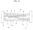
- FIG. 10 illustrates a state in which the plug contact portion is engaged to the receptacle contact portion in accordance with a modified example of the first example
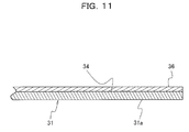
- FIG. 11 is an enlarged view illustrating the plug contact portion in accordance with a second example of an embodiment of the present invention.
- FIG. 12 illustrates a state in which the plug contact portion is engaged to the receptacle contact portion in the connector structure in accordance with the second example
- FIG. 13 is an enlarged view illustrating the receptacle contacting portion and a partition wall in the housing in accordance with a third example of an embodiment of the present invention.
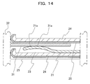
- FIG. 14 illustrates a state in which the plug contact portion is engaged to the receptacle contact portion in the connector structure in accordance with the third example.
- FIG. 1 is a perspective view illustrating a receptacle connector 20 in a connector structure 1.
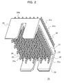
- FIG. 2 is a perspective view illustrating a plug connector 30 in the connector structure 1.
- FIG. 3 is a side view illustrating the connector structure 1 before engaging.
- FIG. 4 schematically illustrates an inside of a server 60, which is an example of an electronic device using the connector structure.
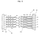
- FIG. 5 schematically illustrates the receptacle connector 20 and the plug connector 30 in the connector structure 1 before engaging.
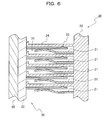
- FIG. 6 schematically illustrates the receptacle connector 20 and the plug connector 30 in the connector structure 1 after engaging.
- the connector structure 1 has the receptacle connector 20 and the plug connector 30 which is engaged into the receptacle connector 20.
- the receptacle connector 20 has a terminal 21 on which a receptacle contact portion 21a is provided.
- the receptacle connector 20 has a housing 22 into which glass fibers, as an example of a fiber material, is impregnated.
- the housing 22 has a plurality of storage spaces 23 in which each of the receptacle contact portion 21a is stored.
- the terminal 21 is bent at 90 degrees in the vicinity of the middle, at one end of which there is formed the receptacle contact portion 21a and at the other end of which there is provided an insertion end portion 21b which is inserted into a pinhole (not shown) which is provided on a board 40.
- the receptacle contact portion 21a is formed into a convex shape. As depicted in FIG. 3 , the receptacle connector 20 is mounted on the board 40.
- the housing 22 has an engaging portion 22a at the upper edge and an engaging portion 22b at the lower edge.
- each of frame plates 33 in the plug connector 30 is engaged to the engaging portions 22a and 22b of the housing.
- the plug connector 30 has terminals 31 which are fixed to a base plate 32.
- a plug contact portion 31a is provided at one end side of the terminal 31, and an insertion end portion 31b is provided at the other end side, which is inserted into a pinhole (not shown) provided on a board 50.
- the base plate 32 has a pair of frame plates 33 which is connected to the upper end and the lower end of the base plate 32.
- the frame plates 33 extend in a direction perpendicular to the base plate 32.
- the connector structure 1 is used in the server 60, which is an example of an electronic device.
- the server 60 has a motherboard 50 provided in the enclosure 61.
- the motherboard 50 is connected to a board 40 such as a daughterboard.
- the connector structure 1 is used to connect between the motherboard 50 and the board 40.
- FIG. 7 is an enlarged view illustrating the plug contact portion 31a of the terminal 31.
- a projection 35 is provided on an upper surface 34 of the plug contact portion 31a facing the partition wall 24 in the storage space 23.
- the projection 35 may be regarded as "contact inhibition member" of the present invention.
- FIG. 8 illustrates a state in which the plug contact portion 31a is engaged to the receptacle contact portion 21a in the connector structure 1.
- the projection 35 is placed in a position closer to the distal side of the terminal 31 away from the contact point P1 with the receptacle contact portion 21a.
- the projection 35 contacts the partition wall 24 to support the terminal 31 against the partition wall 24. Due to the projection 35, the plug contact portion 31a may be suppressed from contacting the partition wall 24.
- FIG. 9 illustrates a state in which the plug contact portion 131a of a comparative example inserted into the storage space 23.
- the plug contact portion 131a of the comparative example does not have a contact inhibition member such as the projection.
- the connector structure according to the comparative example is similar to that of the first example illustrated in FIG. 1 except for the plug contact portion 131a.
- the plug contact portion 31a in the connector structure 1 has a projection 35. Therefore, when the plug contact portion 31a is inserted into the storage space 23, the projection 35 instead of the plug contact portion 31a contacts the partition wall 24 of the storage space 23. Because the projection 35 is small, with just the top of the small projection 35 contacting the partition wall 24, cutting debris of a string shape is difficult to be formed. Even if some cutting debris is formed, the shape may be powder. The powder shaped cutting debris of a powder shape reduces the possibility of short circuit as compared to the string shaped cutting debris 131a1.
- the projection 35 which is provided in the connector structure 1 may suppress the occurrence of string shaped cutting debris. This may narrow the pitch between the terminals 21 of the receptacle connector 20. This may also narrow the pitch between the terminals 31 of the plug connector 30. Accordingly, this may allow the connector structure 1 to be more compact and dense.
- a single projection 35 is provided on the plug contact portion 31a.
- a plurality of projections 35 may be provided to the plug contact portion 31a as depicted in FIG. 10 .
- one of the two projections 35 may be provided closer to a distal side of the terminal 31 away from the contact point P1 between the plug contact portion 31a and the receptacle contact portion 21a while the other may be provided closer to a proximal side of the terminal 31.
- the plug contact portion 31a may be stably supported.
- the plug contact portion 31a may be suppressed from contacting the partition wall 24. Therefore, this may suppress the occurrence of string shaped cutting debris and short circuit.
- FIG. 11 is an enlarged view illustrating the plug contact portion 31a of the terminal 31 in accordance with a second example of an embodiment.
- FIG. 12 illustrates a state in which the plug contact portion 31a is engaged to the receptacle contact portion 21a.
- the same reference numerals in the drawings are assigned to the same components as in the first example, and some details of substantially the same descriptions may not be repeated below.
- a cover layer 36 is provided as an example of the contact inhibition member instead of the projection 35 of the first example.
- the cover layer 36 is provided on the upper surface 34 of the plug contact portion 31a facing the partition wall 24 in the storage space 23.
- the cover layer 36 may suppress contact between the plug contact portion 31a and the partition wall 24, and to suppress the plug contact portion 31a from being cut off by glass fibers impregnated in the partition wall 24.
- the cover layer 36 may be formed by metal coating, resin coating, plating, or the like.
- the cover layer 36 is provided by integrating the terminal 31 of metal with resin through insert molding method.
- the cover layer 36 may suppress the plug contact portion 31a from directly contacting the partition wall 24. As a result, the plug contact portion 31a may be suppressed from being cut off by glass fibers impregnated in the partition wall 24. Therefore, this may suppress the occurrence of string shaped cutting debris and short circuit.
- the cover layer 36 may be provided not to disturb an electrical connection between the plug contact portion 31a and the receptacle contact portion 21a.
- the cover layer 36 may suppress the occurrence of string shaped cutting debris. This may narrow the pitch between the terminals 21 of the receptacle connector 20. This may also narrow the pitch between the terminals 31 of the plug connector 30. Accordingly, this may allow the connector structure 1 to be more compact and dense.
- FIG. 13 is an enlarged view illustrating the receptacle contacting portion 21a and a partition wall 24 in the storage space 23.
- FIG. 14 illustrates a state in which the plug contact portion 31a is engaged to the receptacle contact portion 21a.
- the same reference numerals in the drawings are assigned to the same components as in the first example, and some details of substantially the same descriptions may not be repeated below.
- a cover layer 25 is provided as the contact inhibition member instead of the projection 35 of the first example. Furthermore, the cover layer 25 is provided on the partition wall 24 in the storage space 23 facing the plug contact portion 31a unlike the cover layer 36 ( FIGS. 11 and 12 ).
- the cover layer 25 may suppress contact between the plug contact portion 31a and the partition wall 24, and to suppress the plug contact portion 31a from being cut off by glass fibers impregnated in the partition wall 24.
- the cover layer 25 may be formed by metal coating, resin coating, plating, or the like.
- the cover layer 25 is provided by integrating the housing 22 of resin with metal through insert molding.
- the cover layer 25 may suppress the plug contact portion 31a from directly contacting the partition wall 24. As a result, the plug contact portion 31a may be suppressed from being cut off by glass fibers impregnated in the partition wall 24. Therefore, this may suppress the occurrence of string shaped cutting debris and short circuit.
- the cover layer 25 may be provided not to disturb an electrical connection between the plug contact portion 31a and the receptacle contact portion 21a.
- the cover layer 36 may suppress the occurrence of string shaped cutting debris. This may narrow the pitch between the terminals 21 of the receptacle connector 20. This may also narrow the pitch between the terminals 31 of the plug connector 30. Accordingly, this may allow the connector structure 1 to be more compact and dense.
- the terminal 21 of the receptacle connector 20 is formed bent at 90 degrees, the direction of extending the terminal 21 is not limited. Also, the direction of extending the terminal 31 of the plug connector 30 is not limited. Also, the server 60 has been presented as an example of the electronic device using the connector structure 1, but the connector structure 1 may be adopted for other devices such as a storage device and a communication device.
Landscapes
- Connector Housings Or Holding Contact Members (AREA)
- Coupling Device And Connection With Printed Circuit (AREA)
Applications Claiming Priority (1)
| Application Number | Priority Date | Filing Date | Title |
|---|---|---|---|
| JP2008192874A JP5163340B2 (ja) | 2008-07-25 | 2008-07-25 | コネクタ構造、プラグコネクタ及び電子機器 |
Publications (2)
| Publication Number | Publication Date |
|---|---|
| EP2148394A2 true EP2148394A2 (de) | 2010-01-27 |
| EP2148394A3 EP2148394A3 (de) | 2011-07-20 |
Family
ID=41170904
Family Applications (1)
| Application Number | Title | Priority Date | Filing Date |
|---|---|---|---|
| EP09165923A Withdrawn EP2148394A3 (de) | 2008-07-25 | 2009-07-20 | Steckerstruktur, Stecker, Steckdose und elektronisches Gerät |
Country Status (3)
| Country | Link |
|---|---|
| US (1) | US8092259B2 (de) |
| EP (1) | EP2148394A3 (de) |
| JP (1) | JP5163340B2 (de) |
Cited By (1)
| Publication number | Priority date | Publication date | Assignee | Title |
|---|---|---|---|---|
| WO2013087487A3 (en) * | 2011-12-16 | 2014-07-17 | Tyco Electronics Amp Gmbh | Electrical plug type connector having a microstructured contact element |
Citations (4)
| Publication number | Priority date | Publication date | Assignee | Title |
|---|---|---|---|---|
| US4068103A (en) * | 1975-06-05 | 1978-01-10 | Essex Group, Inc. | Loudspeaker solderless connector system and method of setting correct pigtail length |
| JPH09283234A (ja) | 1995-12-28 | 1997-10-31 | Berg Technol Inc | 保持特性を改善した電気コネクタおよびこれに使用するレセプタクル |
| JP2004288848A (ja) | 2003-03-20 | 2004-10-14 | Nippon Valqua Ind Ltd | 高周波用積層基板およびその製造方法 |
| JP2008192874A (ja) | 2007-02-06 | 2008-08-21 | Omron Corp | 光センサ用受光パッケージおよび光センサ |
Family Cites Families (14)
| Publication number | Priority date | Publication date | Assignee | Title |
|---|---|---|---|---|
| US2248082A (en) * | 1938-02-02 | 1941-07-08 | William P Herman | Contact plug assembly |
| US4929193A (en) * | 1988-11-22 | 1990-05-29 | North American Specialities Corporation | Connector |
| US5028492A (en) * | 1990-03-13 | 1991-07-02 | Olin Corporation | Composite coating for electrical connectors |
| US5235743A (en) * | 1990-07-11 | 1993-08-17 | Yazaki Corporation | Method of manufacturing a pair of terminals having a low friction material on a mating surface to facilitate connection of the terminals |
| JPH074782Y2 (ja) * | 1990-09-17 | 1995-02-01 | ヒロセ電機株式会社 | 電気コネクタ構造 |
| US5232743A (en) * | 1991-02-01 | 1993-08-03 | Allied-Signal Inc. | Method and composition to enhance acid dye stain resistance of polyamides by improving resistance to detergent washings and products thereof |
| US5230632A (en) * | 1991-12-19 | 1993-07-27 | International Business Machines Corporation | Dual element electrical contact and connector assembly utilizing same |
| US6537091B2 (en) * | 2000-11-28 | 2003-03-25 | Autonetworks Technologies, Ltd. | Arc discharge suppressive terminal, method for producing such terminal, and arc discharge suppressive connector |
| JP3894774B2 (ja) * | 2001-10-31 | 2007-03-22 | 富士通株式会社 | カードエッジコネクタ及びその製造方法、電子カードならびに電子機器 |
| JP2005051129A (ja) | 2003-07-30 | 2005-02-24 | Sony Corp | 電子機器 |
| JP2005347094A (ja) * | 2004-06-03 | 2005-12-15 | Auto Network Gijutsu Kenkyusho:Kk | コネクタ |
| DE102005005127A1 (de) | 2005-02-04 | 2006-08-10 | Robert Bosch Gmbh | Elektrischer Kontakt und Verfahren zu dessen Herstellung |
| US20090253284A1 (en) * | 2006-07-27 | 2009-10-08 | Jean-Francois Michel | Electrical connector and method of manufacturing |
| JP2008108675A (ja) * | 2006-10-27 | 2008-05-08 | Toshiba Corp | プラグ |
-
2008
- 2008-07-25 JP JP2008192874A patent/JP5163340B2/ja not_active Expired - Fee Related
-
2009
- 2009-07-15 US US12/503,601 patent/US8092259B2/en not_active Expired - Fee Related
- 2009-07-20 EP EP09165923A patent/EP2148394A3/de not_active Withdrawn
Patent Citations (4)
| Publication number | Priority date | Publication date | Assignee | Title |
|---|---|---|---|---|
| US4068103A (en) * | 1975-06-05 | 1978-01-10 | Essex Group, Inc. | Loudspeaker solderless connector system and method of setting correct pigtail length |
| JPH09283234A (ja) | 1995-12-28 | 1997-10-31 | Berg Technol Inc | 保持特性を改善した電気コネクタおよびこれに使用するレセプタクル |
| JP2004288848A (ja) | 2003-03-20 | 2004-10-14 | Nippon Valqua Ind Ltd | 高周波用積層基板およびその製造方法 |
| JP2008192874A (ja) | 2007-02-06 | 2008-08-21 | Omron Corp | 光センサ用受光パッケージおよび光センサ |
Cited By (2)
| Publication number | Priority date | Publication date | Assignee | Title |
|---|---|---|---|---|
| WO2013087487A3 (en) * | 2011-12-16 | 2014-07-17 | Tyco Electronics Amp Gmbh | Electrical plug type connector having a microstructured contact element |
| US9590340B2 (en) | 2011-12-16 | 2017-03-07 | Te Connectivity Germany Gmbh | Electrical plug type connector having a microstructured contact element |
Also Published As
| Publication number | Publication date |
|---|---|
| JP2010033787A (ja) | 2010-02-12 |
| JP5163340B2 (ja) | 2013-03-13 |
| US20100022139A1 (en) | 2010-01-28 |
| US8092259B2 (en) | 2012-01-10 |
| EP2148394A3 (de) | 2011-07-20 |
Similar Documents
| Publication | Publication Date | Title |
|---|---|---|
| JP5602617B2 (ja) | コネクタ部材 | |
| EP2922151A1 (de) | Steckverbinder | |
| JP4722707B2 (ja) | 垂直嵌合雌端子及びこれが装着されるハウジング | |
| CN101228674B (zh) | 连接器 | |
| KR102076174B1 (ko) | 커넥터 | |
| CN1988271A (zh) | 电连接器 | |
| JP2000223215A (ja) | 小型コネクタ | |
| KR20080008250A (ko) | 평형 도체용 전기 커넥터 | |
| JP7086620B2 (ja) | コネクタおよびコネクタシステム | |
| CN103403973A (zh) | 连接器端子及包含该连接器端子的卡缘型连接器 | |
| JP3122673U (ja) | カード用コネクタ装置 | |
| JP2009104851A (ja) | コネクタ | |
| JP4290184B2 (ja) | 低背コネクタ | |
| JP4789576B2 (ja) | 電気コネクタ | |
| CN103078209A (zh) | 连接器 | |
| JP5083690B2 (ja) | メモリーカード用コネクタ | |
| US8092259B2 (en) | Connector structure, plug connector, receptacle connector and electronic device | |
| TWM320206U (en) | Electrical card connector | |
| JP6467224B2 (ja) | 電気コネクタ | |
| JP4558562B2 (ja) | コネクタ | |
| JP2007287420A (ja) | ケーブル接続用コネクタ | |
| JP5431038B2 (ja) | 端子及びそれを有するコネクタ | |
| JP2008130263A (ja) | フラットケーブル用電気コネクタ | |
| JP2014035946A (ja) | 基板搭載型シールドコネクタ | |
| CN102544854A (zh) | 具有至少2个以上配合口的壳体的连结结构及由该连结结构形成的壳体、具有该壳体的连接器 |
Legal Events
| Date | Code | Title | Description |
|---|---|---|---|
| PUAI | Public reference made under article 153(3) epc to a published international application that has entered the european phase |
Free format text: ORIGINAL CODE: 0009012 |
|
| AK | Designated contracting states |
Kind code of ref document: A2 Designated state(s): AT BE BG CH CY CZ DE DK EE ES FI FR GB GR HR HU IE IS IT LI LT LU LV MC MK MT NL NO PL PT RO SE SI SK SM TR |
|
| AX | Request for extension of the european patent |
Extension state: AL BA RS |
|
| REG | Reference to a national code |
Ref country code: DE Ref legal event code: R079 Free format text: PREVIOUS MAIN CLASS: H01R0012160000 Ipc: H01R0013030000 |
|
| PUAL | Search report despatched |
Free format text: ORIGINAL CODE: 0009013 |
|
| AK | Designated contracting states |
Kind code of ref document: A3 Designated state(s): AT BE BG CH CY CZ DE DK EE ES FI FR GB GR HR HU IE IS IT LI LT LU LV MC MK MT NL NO PL PT RO SE SI SK SM TR |
|
| AX | Request for extension of the european patent |
Extension state: AL BA RS |
|
| RIC1 | Information provided on ipc code assigned before grant |
Ipc: H01B 3/47 20060101ALI20110616BHEP Ipc: H01R 13/03 20060101AFI20110616BHEP |
|
| 17P | Request for examination filed |
Effective date: 20120120 |
|
| 17Q | First examination report despatched |
Effective date: 20140603 |
|
| STAA | Information on the status of an ep patent application or granted ep patent |
Free format text: STATUS: THE APPLICATION IS DEEMED TO BE WITHDRAWN |
|
| 18D | Application deemed to be withdrawn |
Effective date: 20161220 |