EP2145864B1 - Verfahren und Vorrichtung zur Herstellung von Quarzglas - Google Patents
Verfahren und Vorrichtung zur Herstellung von Quarzglas Download PDFInfo
- Publication number
- EP2145864B1 EP2145864B1 EP09165709.8A EP09165709A EP2145864B1 EP 2145864 B1 EP2145864 B1 EP 2145864B1 EP 09165709 A EP09165709 A EP 09165709A EP 2145864 B1 EP2145864 B1 EP 2145864B1
- Authority
- EP
- European Patent Office
- Prior art keywords
- hydrogen
- quartz glass
- glass manufacturing
- flow rate
- burners
- Prior art date
- Legal status (The legal status is an assumption and is not a legal conclusion. Google has not performed a legal analysis and makes no representation as to the accuracy of the status listed.)
- Active
Links
Images




Classifications
-
- C—CHEMISTRY; METALLURGY
- C03—GLASS; MINERAL OR SLAG WOOL
- C03B—MANUFACTURE, SHAPING, OR SUPPLEMENTARY PROCESSES
- C03B37/00—Manufacture or treatment of flakes, fibres, or filaments from softened glass, minerals, or slags
- C03B37/01—Manufacture of glass fibres or filaments
- C03B37/012—Manufacture of preforms for drawing fibres or filaments
- C03B37/014—Manufacture of preforms for drawing fibres or filaments made entirely or partially by chemical means, e.g. vapour phase deposition of bulk porous glass either by outside vapour deposition [OVD], or by outside vapour phase oxidation [OVPO] or by vapour axial deposition [VAD]
- C03B37/01413—Reactant delivery systems
-
- C—CHEMISTRY; METALLURGY
- C03—GLASS; MINERAL OR SLAG WOOL
- C03B—MANUFACTURE, SHAPING, OR SUPPLEMENTARY PROCESSES
- C03B37/00—Manufacture or treatment of flakes, fibres, or filaments from softened glass, minerals, or slags
- C03B37/01—Manufacture of glass fibres or filaments
- C03B37/012—Manufacture of preforms for drawing fibres or filaments
- C03B37/014—Manufacture of preforms for drawing fibres or filaments made entirely or partially by chemical means, e.g. vapour phase deposition of bulk porous glass either by outside vapour deposition [OVD], or by outside vapour phase oxidation [OVPO] or by vapour axial deposition [VAD]
- C03B37/01413—Reactant delivery systems
- C03B37/0142—Reactant deposition burners
-
- C—CHEMISTRY; METALLURGY
- C03—GLASS; MINERAL OR SLAG WOOL
- C03B—MANUFACTURE, SHAPING, OR SUPPLEMENTARY PROCESSES
- C03B2201/00—Type of glass produced
- C03B2201/02—Pure silica glass, e.g. pure fused quartz
-
- C—CHEMISTRY; METALLURGY
- C03—GLASS; MINERAL OR SLAG WOOL
- C03B—MANUFACTURE, SHAPING, OR SUPPLEMENTARY PROCESSES
- C03B2201/00—Type of glass produced
- C03B2201/06—Doped silica-based glasses
- C03B2201/30—Doped silica-based glasses doped with metals, e.g. Ga, Sn, Sb, Pb or Bi
- C03B2201/31—Doped silica-based glasses doped with metals, e.g. Ga, Sn, Sb, Pb or Bi doped with germanium
-
- C—CHEMISTRY; METALLURGY
- C03—GLASS; MINERAL OR SLAG WOOL
- C03B—MANUFACTURE, SHAPING, OR SUPPLEMENTARY PROCESSES
- C03B2207/00—Glass deposition burners
- C03B2207/36—Fuel or oxidant details, e.g. flow rate, flow rate ratio, fuel additives
-
- C—CHEMISTRY; METALLURGY
- C03—GLASS; MINERAL OR SLAG WOOL
- C03B—MANUFACTURE, SHAPING, OR SUPPLEMENTARY PROCESSES
- C03B2207/00—Glass deposition burners
- C03B2207/70—Control measures
-
- C—CHEMISTRY; METALLURGY
- C03—GLASS; MINERAL OR SLAG WOOL
- C03B—MANUFACTURE, SHAPING, OR SUPPLEMENTARY PROCESSES
- C03B2207/00—Glass deposition burners
- C03B2207/80—Feeding the burner or the burner-heated deposition site
- C03B2207/85—Feeding the burner or the burner-heated deposition site with vapour generated from liquid glass precursors, e.g. directly by heating the liquid
-
- C—CHEMISTRY; METALLURGY
- C03—GLASS; MINERAL OR SLAG WOOL
- C03B—MANUFACTURE, SHAPING, OR SUPPLEMENTARY PROCESSES
- C03B2207/00—Glass deposition burners
- C03B2207/80—Feeding the burner or the burner-heated deposition site
- C03B2207/85—Feeding the burner or the burner-heated deposition site with vapour generated from liquid glass precursors, e.g. directly by heating the liquid
- C03B2207/87—Controlling the temperature
-
- Y—GENERAL TAGGING OF NEW TECHNOLOGICAL DEVELOPMENTS; GENERAL TAGGING OF CROSS-SECTIONAL TECHNOLOGIES SPANNING OVER SEVERAL SECTIONS OF THE IPC; TECHNICAL SUBJECTS COVERED BY FORMER USPC CROSS-REFERENCE ART COLLECTIONS [XRACs] AND DIGESTS
- Y02—TECHNOLOGIES OR APPLICATIONS FOR MITIGATION OR ADAPTATION AGAINST CLIMATE CHANGE
- Y02P—CLIMATE CHANGE MITIGATION TECHNOLOGIES IN THE PRODUCTION OR PROCESSING OF GOODS
- Y02P40/00—Technologies relating to the processing of minerals
- Y02P40/50—Glass production, e.g. reusing waste heat during processing or shaping
- Y02P40/57—Improving the yield, e-g- reduction of reject rates
Definitions
- the present invention relates to manufacturing of quartz glass, such as that used as an optical fiber base material, obtained by depositing silicon dioxide (SiO 2 ) generated by a flame hydrolysis reaction.
- the present invention relates to a quartz glass manufacturing method and a quartz glass manufacturing apparatus using, as backup, hydrogen obtained by vaporizing liquid hydrogen.
- Currently used hydrogen supply equipment stores liquid hydrogen in a low-temperature storage chamber, heats and vaporizes the liquid hydrogen, and supplies the resulting gas to a device connected at a later stage.
- a device connected at a later stage For example, when manufacturing quartz glass with a high degree of purity, techniques such as VAD or OVD may be used.
- Both of these techniques involve (i) generating silicon dioxide (Si0 2 ) through a hydrolysis reaction achieved by supplying a silicide such as silicon tetrachloride (SiCl 4 ) to an oxyhydrogen flame fueled by supplying hydrogen and oxygen to a burner, (ii) depositing the silicon dioxide to form a porous base material, and (iii) heating the porous base material in an electric furnace to form transparent quartz glass with a high degree of purity.
- a silicide such as silicon tetrachloride (SiCl 4 )
- Manufacturing quartz glass using the VAD technique involves forming the porous base material by simultaneously rotating SiO 2 , generated by a flame hydrolysis reaction, and depositing the Si0 2 on a starting material that can be lifted. During deposition, the position of the deposition tip of the porous base material is detected and the lifting speed is adjusted as the base material grows. As shown in Japanese Patent Application Publication No. 1-239033 , however, when the lifting speed is held constant during deposition, it is necessary to detect the a deviation from the set value of the lifting speed at predetermined times and to correct the flow rate of the raw material gas such as SiCl 4 according to the detected deviation, in order to obtain stable optical fiber base material with the desired refractive index distribution. In Japanese Patent Application Publication No. 3-242341 , in order to maintain a constant lifting speed, the flow rate of the hydrogen supplied to clad burners adjacent to a core burner, from among a plurality of clad burners, is controlled.
- Manufacturing quartz glass using the OVD technique involves forming the porous base material by rotating the starting material and moving the deposition burner back and forth along the starting material to deposit silicon dioxide around the starting material.
- the porous base material formed in this way is then heated to about 1500 degrees Celsius in a heating furnace, resulting in transparent quartz glass.
- the inside of the furnace is often a helium atmosphere in order to decrease residual air bubbles in the glass.
- a dehydration process is performed by heating the porous base material in an atmosphere containing chlorine at a temperature between 1000 and 1200 degrees Celsius, before being changed into the transparent glass.
- the core deposition burner is often supplied with germanium as the additive for increasing the refractive index of the quartz glass.
- the germanium is supplied as a compound, such as germanium tetrachloride (GeCl 4 ). Germanium tetrachloride undergoes hydrolysis in the oxyhydrogen flame to create GeO 2 .
- SiCl 4 and GeCl 4 are liquid at a normal temperature, and are vaporized before being supplied using techniques such as bubbling with a carrier gas or heating to a temperature above the respective boiling points.
- the flow rate of gas supplied to the burners is controlled by a thermal mass flow controller (MFC).
- MFC thermal mass flow controller
- the hydrogen used here is made at a normal temperature or stored at a normal temperature.
- One idea involves heating and vaporizing liquid hydrogen stored in a low-temperature storage chamber to supply backup hydrogen when the supply of the above hydrogen is stopped.
- one exemplary quartz glass manufacturing method may include a quartz glass manufacturing method that involves using one or more burners, supplying hydrogen and oxygen to the one or more burners to generate an oxyhydrogen flame, introducing a silicide into the oxyhydrogen flame, forming a porous base material by depositing silicon dioxide generated from a flame hydrolysis reaction with the silicide, and heating and sintering the porous base material to form transparent glass, the quartz glass manufacturing method comprising supplying hydrogen that is stored or made at a normal temperature to the one or more burners; controlling a hydrogen flow rate using a measurement apparatus or control apparatus that performs measurement based on heat capacity of a gas; vaporizing liquid hydrogen stored in a low-temperature storage chamber, and supplying the vaporized liquid hydrogen to the one or more burners as backup hydrogen; switching from the hydrogen to the backup hydrogen; and when switching, adjusting the hydrogen flow rate to a value obtained by multiplying the hydrogen flow rate immediately after switching by a predetermined correction coefficient.
- one exemplary quartz glass manufacturing apparatus may include a quartz glass manufacturing apparatus that uses one or more burners, supplies hydrogen and oxygen to the one or more burners to generate a oxyhydrogen flame, introduces a silicide into the oxyhydrogen flame, forms a porous base material by depositing silicon dioxide generated from a flame hydrolysis reaction with the silicide, and heats and sintering the porous base material to form transparent glass, the quartz glass manufacturing apparatus comprising first hydrogen supply equipment that supplies hydrogen that is stored or made at a normal temperature to the one or more burners; second hydrogen supply equipment that includes at least a low-temperature storage chamber and a vaporizer, and that uses the vaporizer to vaporize liquid hydrogen stored in the low-temperature storage chamber to generate and supply backup hydrogen as a backup for the hydrogen that is stored or made at the normal temperature; a measurement apparatus or control apparatus that performs measurement based on heat capacity of a gas to control a hydrogen flow rate; and a correction apparatus that, when the switching to
- Fig. 1 is a schematic view showing the spin states of orthohydrogen and parahydrogen.
- Fig. 2 shows the parahydrogen concentration in equilibrium at each temperature.
- the vertical axis is the parahydrogen concentration (%) and the horizontal axis is the temperature (K).
- Fig. 3 shows an exemplary configuration of a quartz glass manufacturing apparatus 10 according to an embodiment of the present invention.
- Fig. 4 is a schematic view showing the supply of hydrogen.
- Fig. 5 is a schematic view showing the method for manufacturing an optical fiber base material using the VAD technique.
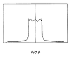
- Fig. 6 is a schematic view showing the refractive index distribution of an optical base material manufactured using the VAD technique.
- the vertical axis represents the relative refractive index difference, and the horizontal axis represents a radial position on the preform.
- Fig. 7A shows a change in the lifting speed when the hydrogen supplied to the optical fiber base material manufacturing apparatus using the VAD technique, according to an embodiment of the present invention, is switched from normal hydrogen to hydrogen obtained by vaporizing liquid hydrogen.
- the vertical axis represents the lifting speed (mm/min) of the soot deposit body, and the horizontal axis represents time from left to right, where each partition is approximately 2.4 seconds.
- Fig. 7B shows a change in the lifting speed of a comparative example.
- Fig. 8 is a schematic view showing a method for manufacturing an optical fiber base material using the OVD technique.
- the pressure and temperature of the hydrogen is held to be about the same before and after the switching of the hydrogen, and no difference is seen connecting a change in the flow rate of the hydrogen to the purity or impurity concentration of the liquid hydrogen and the hydrogen made at a normal temperature.
- Fig. 1 there are two types of hydrogen molecule isomers having different nuclear spin. Diatomic molecules such as hydrogen molecules have two protons. Hydrogen molecules in which these two protons have the same spin orientation are known as orthohydrogen, and hydrogen molecules in which these two protons have different spin orientation are known as parahydrogen.
- Fig. 2 shows parahydrogen concentration in equilibrium at each temperature.
- the hydrogen includes orthohydrogen and parahydrogen at a ratio of 3 to 1, but in equilibrium near the boiling point of liquid hydrogen, which is 20 K, almost all of the hydrogen is parahydrogen.
- Hydrogen in which orthohydrogen and parahydrogen are in equilibrium at a normal temperature is referred to as normal hydrogen.
- the change from orthohydrogen to parahydrogen occurs gradually, and since this change is a thermal reaction, when the hydrogen at a normal temperature is used as the liquid hydrogen without changing the ratio between the orthohydrogen and the parahydrogen, the conversion from orthohydrogen to parahydrogen occurs in the low-temperature storage chamber and generates heat, so that a large amount of liquid hydrogen evaporates.
- a thermal MFC used to control the flow rate of the hydrogen performs this control by measuring the heat capacity of the liquid passing therethrough, and therefore can accurately control the flow rate by using a different conversion factor for liquids having different specific heat.
- an MFC using a thermal coefficient suitable for normal hydrogen controls the flow rate of hydrogen in which the concentration of parahydrogen is higher than that of normal hydrogen, it was found that the actual flow rate is between 0% and 6% less than normal hydrogen, according to the concentration of parahydrogen. For example, when the parahydrogen concentration was about 37%, the actual hydrogen flow rate was seen to be about 1% less than the flow rate of normal hydrogen. This change of up to 6% in the actual flow rate of the hydrogen has an effect on the optical characteristics of the resulting manufactured article that increases the rate of defective articles.
- a correction coefficient is set in advance for each flow rate so that, when switching from normal hydrogen to hydrogen obtained by vaporizing backup liquid hydrogen, the control value of the MFC increases the hydrogen flow rate by 1 ⁇ .02% for each apparatus.
- the actual flow rate of the hydrogen supplied to the core deposition burner and a clad deposition burner can be held constant.
- the resulting optical fiber base material has stable optical characteristics in a longitudinal direction. This adjustment that accompanies the switching may be performed for each apparatus, or may be adapted to allow centralized control. Centralized control allows for simpler operation.
- the SiCl 4 and GeCl 4 are desirably supplied after being heated to a temperature above their respective boiling points and directly vaporized. With this method, any raw material gas concentration can be accurately achieved. Another gas such as helium may be added to the supply such that the vaporized gas does not contract and re-liquefy while traveling to the burner.
- Another method for supplying the SiCl 4 and GeCl 4 involves bubbling with a carrier gas and vaporizing the SiCl 4 and GeCl 4 . However, this is not a desirable method because the mixture of the carrier gas and raw material gas has a raw material gas concentration that varies at high pressure.
- Fig. 3 shows an exemplary configuration of a quartz glass manufacturing apparatus 10 according to an embodiment of the present invention.
- the quartz glass manufacturing apparatus 10 is provided with silicon tetrachloride supply equipment 100, first hydrogen supply equipment 120, second hydrogen supply equipment 140, a hydrogen supply source switcher 150, a mass flow controller 160, a correction apparatus 180, and a VAD apparatus 200.
- An optical fiber base material manufacturing apparatus forms optical fiber base material through VAD by sequentially depositing fine glass particles on a tip of a starting material that is being lifted and rotated.
- the silicon tetrachloride supply equipment 100 supplies the VAD apparatus 200 with silicon tetrachloride (SiCl 4 ).
- the first hydrogen supply equipment 120 supplies hydrogen made at a normal temperature or hydrogen stored at a normal temperature to a burner provided to the VAD apparatus 200.
- the second hydrogen supply equipment 140 is provided with the low-temperature storage chamber 142 and the vaporizer 144, uses the vaporizer 144 to vaporize the liquid hydrogen stored in the low-temperature storage chamber 142, and supplies the vaporized hydrogen to the burner provided to the VAD apparatus 200.
- the hydrogen supplied from the second hydrogen supply equipment 140 may be used as backup for the hydrogen supplied from the first hydrogen supply equipment 120.
- the hydrogen supply source switcher 150 switches between the first hydrogen supply equipment 120 and the second hydrogen supply equipment 140 as the source supplying the hydrogen to the VAD apparatus 200.
- the hydrogen supply source switcher 150 may be provided with a first valve 152 disposed in the hydrogen supply line from the first hydrogen supply equipment 120 and a second valve 154 disposed in the hydrogen supply line from the second hydrogen supply equipment 140.
- the mass flow controller 160 measures the flow rate of the hydrogen and controls the flow rate to be a set value.
- the mass flow controller 160 desirably performs this measurement based on the heat capacity of the gas.
- the correction apparatus 180 includes a detecting section 182, a set value storage section 184, a correction coefficient storage section 186, and a correction calculating section 188.
- the correction apparatus 180 performs suitable corrections on the set value for the amount of hydrogen supplied to the VAD apparatus 200, and sets the corrected value in the mass flow controller 160.
- the correction apparatus 180 corrects the set value of the hydrogen flow rate to be equal to the product of the flow rate immediately after the switch and a predetermined correction coefficient.
- the detecting section 182 detects the switch of the hydrogen supply source from the first hydrogen supply equipment 120 to the second hydrogen supply equipment 140.
- the detecting section 182 may detect the switching of the hydrogen source by observing which of the first valve 152 and the second valve 154 is open. Instead, the detecting section 182 may detect the switching of the hydrogen source by observing the ratio of orthohydrogen to parahydrogen in the hydrogen supplied to the mass flow controller 160.
- the set value storage section 184 stores the set value of the hydrogen flow rate.
- the correction coefficient storage section 186 stores the correction coefficient used when correcting the flow rate of the hydrogen supplied to the VAD apparatus 200.
- the correction calculating section 188 multiplies the coefficient stored in the correction coefficient storage section 186 by the set value of the hydrogen flow rate stored in the set value storage section 184, and sets the result in the mass flow controller 160 as the corrected set value.
- the correction calculating section 188 may set the mass flow controller 160 to have the set value of the hydrogen flow rate stored in the set value storage section 184.
- the VAD apparatus 200 is provided with the core deposition burner and the clad deposition burner, and deposits fine glass particles by causing a reaction between silicon tetrachloride and hydrogen supplied thereto.
- the liquid hydrogen that was developed and provided for commercial use was stored in a liquid hydrogen container.
- the liquid hydrogen was vaporized by a vaporizer and emitted as hydrogen gas at a stage beyond the hydrogen supply equipment to be mixed in a pipe with hydrogen made at a normal temperature (referred to hereinafter as "normal hydrogen") and supplied to equipment that uses hydrogen.
- normal hydrogen a normal temperature
- the pipe of the liquid hydrogen supply line and the pipe of the normal hydrogen supply line are each provided with a valve immediately before the point where the pipes join, so that each line can be used independently.
- Fig. 5 is a schematic view of the VAD apparatus as an embodiment of the present invention.
- the VAD apparatus includes a core deposition burner, and a clad deposition burner positioned thereabove. These burners were each supplied with hydrogen, oxygen, non-volatile gas, and vaporized SiCl 4 as the raw material, all of which have a flow rate controlled by an MFC.
- the supply of hydrogen to the VAD apparatus was set to normal hydrogen by closing the valve in the liquid hydrogen supply line.
- the SiCl 4 supplied to the oxyhydrogen flame changed to Si0 2 due to the hydrolysis reaction, and the Si02 was sequentially deposited on the tip of a target being lifted and rotated to form a soot deposition body.
- the tip of the soot deposition body was observed by a camera (CCD), and a PID controller adjusted the lifting speed according to the length of the soot deposit body to prevent the tip position from rising or falling.
- the bottom core deposition burner was supplied with GeCl 4 .
- the GeCl 4 changed to Ge0 2 due to the flame hydrolysis, and this GeO 2 was added to the resulting manufactured quartz glass to increase the refractive index.
- the GeCl 4 only to the core deposition burner, only the refractive index of the core portion increases.
- the vertical axis represents the relative refractive index difference
- the horizontal axis represents a radial position on the preform.
- the supply of hydrogen to the core deposition burner and the clad deposition burner was switched from the normal hydrogen to the hydrogen obtained by vaporizing liquid hydrogen and, at the same time, the control value of the MFC of each piece of manufacturing equipment was increased by 1% from the value obtained as a product of the hydrogen flow rate immediately after switching and the correction coefficient.
- the actual flow rate of hydrogen is the same before and after the switching and, as shown in Fig. 7A , no abnormalities are seen in the lifting speed before and after the switching. Therefore, the optical fiber preform formed by changing the resulting soot deposit body into transparent glass has stable optical characteristics in a longitudinal direction.
- the vertical axes represent the lifting speed (mm/min) of the soot deposit body, and the horizontal axes represent time from left to right, where each partition is approximately 2.4 seconds.
- the control value of the MFC provided to each piece of manufacturing equipment is increased by 1%, in the same manner. As a result, no difference was seen in the density of the resulting porous base material when the normal hydrogen was used and when the hydrogen obtained from vaporizing liquid hydrogen was used.
- An optical fiber preform was manufactured in the same way as in the First Embodiment, except that, when switching from the normal hydrogen to the hydrogen obtained by vaporizing liquid hydrogen, the hydrogen flow rate was not corrected. As a result, the actual flow rate of the hydrogen differed before and after the switching and the lifting speed increased by 2%, as shown in Fig. 7B .
- the optical fiber preform formed by changing the resulting soot deposit body into transparent glass was unusable because, due to the above difference, there was a change in the refractive index distribution, core diameter, and clad diameter. Furthermore, in a portion of the apparatus, the soot deposition body cracked.
- This cracking is believed to have occurred due to the actual flow rate of the hydrogen changing rapidly at the time of the switching, which caused the density to change quickly.
- the switching was also performed for each OVD apparatus without adjusting the control value of the MFCs.
- the density of the manufactured porous base material decreased by about 1.5%. Therefore, the outer diameter increased to a point where the base material was too large to be inserted into a heating furnace for further processing, and so could not be turned into transparent glass.
- an actual flow rate of hydrogen can be held constant, even when a supply of hydrogen is switched to backup hydrogen obtained by vaporizing liquid hydrogen, by multiplying the hydrogen flow rate immediately after the switching by a predetermined correction coefficient.
- the optical characteristics of a quartz glass optical fiber preform made using VAD can be stabilized.
- defects caused by a change in density during manufacturing of quartz glass using OVD can be prevented. Therefore, the embodiments of the present invention can be used to achieve optical fiber base material with stable optical characteristics and high yield, thereby enabling higher productivity.
Landscapes
- Chemical & Material Sciences (AREA)
- Engineering & Computer Science (AREA)
- Chemical Kinetics & Catalysis (AREA)
- General Chemical & Material Sciences (AREA)
- Life Sciences & Earth Sciences (AREA)
- General Life Sciences & Earth Sciences (AREA)
- Geochemistry & Mineralogy (AREA)
- Manufacturing & Machinery (AREA)
- Materials Engineering (AREA)
- Organic Chemistry (AREA)
- Manufacture, Treatment Of Glass Fibers (AREA)
- Glass Melting And Manufacturing (AREA)
Claims (12)
- Quarzglasherstellungoverfahren, das das Verwenden eines oder mehrerer Brenner, das Zuführen von Wasserstoff und Sauerstoff zu dem einen oder den mehreren Brennern, um eine Wasserstoff-Sauerstoff-Flamme zu erzeugen, das Einbringen eines silicids in die wasserstoff-Sauerstoff-Flamme, das Bilden eines porösen Grundmaterials durch Ablagern von Siliziumdioxid, das aus einer Flammenhydrolysereaktion mit dem Silicid gebildet ist, und das Erhitzen und Sintern des porösen Grundmaterials, um durchsichtiges Glas zu bilden, beinhaltet, wobei das Quarzglasherstellungsverfahren Folgendes umfasst:Zuführen von Wasserstoff, der bei normaler Temperatur gespeichert oder hergestellt wird, zu dem einen oder den mehreren Brennern;Steuern einer Wasserstoffdurchflussmenge unter Verwendung- einer Messvorrichtung oder Steuervorrichtung, die Messungen basierend auf der Wärmekapazität eines Gases durchführt;verdampfen von flüssigem Wasserstoff, der in einer Tieftemperaturspeicherkammer gespeichert ist, und Zuführen des verdampften flüssigen Wasserstoffs als Reservewasserstoff zu dem einen oder den mehreren Brennern;Schalten von dem Wasserstoff zu dem Reservewasserstoff; undbeim Schalten Einstellen der Wasserstoffdurchflussmenge auf einen Wert, der durch Multiplizieren der wasserstoffdurchflussmenge ummittelbar nach dem Schalten mit einem vorgegebenen Korrekturkoeffizienten erhalten wird.
- Quarzglasherstellungsverfahren nach Anspruch 1, wobei
die Messvorrichtung oder Steuervorrichtung, die Messungen basierend auf der Wärmekapazität eines Gases durchführt, eine Massendurchflusssteuereinheit ist. - Quarzglasherstellungsverfahren nach Anspruch 1, wobei
das Silicid Siliziumtetrachlorid ist. - Quarzglasherstellungsverfahren nach Anspruch 1, wobei
eine Germaniumverbindung zu dem Silicid hinzugefügt wird, das der Flamme wenigstens einen Brenners aus dem einen oder den mehreren Brennern zugeführt wird. - Quarzglasherstellungsverfahren nach Anspruch 4, wobei
die Germaniumverbindung Germaniumtetrachlorid ist. - Quarzglasherstellungsverfahren nach Anspruch 1, wobei
das poröse Grundmaterial durch sequenzielles Ablagern auf einer Spitze eines Anfangsmaterials, das gemäß einer VAD-Technik angehoben und gedreht wird, gebildet wird. - Quarzglasherstellungsverfahren nach Anspruch 1, wobei
das poröse Grundmaterial durch Ablagern um ein Anfangsmaterial, das gemäß einer OVD-Technik gedreht wird, gebildet wird. - Quarzglasherstellungsvorrichtung, die einen oder mehrere Brenner verwendet, Wasserstoff und Sauerstoff zu dem einen oder den mehreren Brennern zuführt, um eine Wasserstoff-Sauerstoff-Flamme zu erzeugen, ein Silicid in die Wasserstoff-Sauerstoff-Flamme einbringt, ein poröses Grundmaterial durch Ablagern von Siliziumdioxid bildet, das aus einer Flammenhydrolysereaktion mit dem Silicid gebildet ist, und das poröse Grundmaterial erhitzt und sintert, um durchsichtiges Glas zu bilden, wobei die Quarzglasherstellungsvorrichtung Folgendes umfasst:eine erste Wasserstoffzufuhreinrichtung, die Wasserstoff, der bei normaler Temperatur gespeichert oder hergestellt wird, dem einen oder den mehreren Brennern zuführt;eine zweite Wasserstoffzufuhreinrichtung, die wenigstens eine Tieftemperaturspeicherkammer und einen verdampfer enthält und die den Verdampfer verwendet, um flüssigen Wasserstoff, der in der Tieftemperaturspeicherkammer gespeichert ist, zu verdampfen, um Reservewasserstoff als eine Reserve für den Wasserstoff, der bei der normalen Temperatur gespeichert oder hergestellt wird, zu erzeugen und zuzuführen;eine Messvorrichtung oder Steuervorrichtung, die Messungen basierend auf der Wärmekapazität eines Gases durchführt, um eine Wasserstoffdurchflussmenge zu steuern; undeine Korrekturvorrichtung, die dann, wenn das Schalten zu dem Reservewasserstoff erfolgt, einen festgesetzten Wert der Wasserstoffdurchflussmenge auf einen Wert einstellt, der durch Multiplizieren der Wasserstoffdurchflussmenge unmittelbar nach dem Schalten mit einem vorgegebenen Korrekturkoeffizienten erhalten wird.
- Quarzglasherstellungevorrichtung nach Anspruch 8, wobei
die Messvorrichtung oder Steuervorrichtung, die die Messungen basierend auf der Wärmekapazität eines Gases durchführt, eine Massendurchflusssteuereinheit ist. - Quarzglasherstellungsvorrichtung nach Anspruch 8, die ferner einen Detektierabschnitt umfasst, der das Schalten einer wasserstoffzufuhrquelle von einer ersten Wasserstoffzufuhrvorrichtung zu einer zweiten Wasserstoffzufuhrvorrichtung detektiert, wobei
die Korrekturvorrichtung Folgendes enthält:einen Korrekturkoeffizientenspeicherabschnitt, der den Korrekturkoeffizienten speichert; undeinen Berechnungsabschnitt, der den Korrekturkoeffizienten mit einem eingestellten Wert der Wasserstoffdurchflussmenge multipliziert, wenn der Detektierabschnitt detektiert hat, dass die Wasserstoffzufuhrquelle von der ersten Wasserstoffzufuhrvorrichtung zu der zweiten Wasserstoffzufuhrvorrichtung geschaltet hat. - Quarzglasherstellungsvorrichtung nach Anspruch 8, wobei
der Korrekturkoeffizient ein Wert ist, der die Wasserstoffdurchflussmenge um etwa 1 % erhöht. - Quarzglashersteollungsvorrichtung nach Anspruch 1, wobei
der Korrekturkoeffizient ein Wert ist, der die Wasserstoffdurchflussmenge um etwa 1 % erhöht.
Applications Claiming Priority (1)
| Application Number | Priority Date | Filing Date | Title |
|---|---|---|---|
| JP2008187924A JP4809401B2 (ja) | 2008-07-18 | 2008-07-18 | 石英ガラスの製造方法及び装置 |
Publications (3)
| Publication Number | Publication Date |
|---|---|
| EP2145864A2 EP2145864A2 (de) | 2010-01-20 |
| EP2145864A3 EP2145864A3 (de) | 2012-03-14 |
| EP2145864B1 true EP2145864B1 (de) | 2013-04-24 |
Family
ID=41201385
Family Applications (1)
| Application Number | Title | Priority Date | Filing Date |
|---|---|---|---|
| EP09165709.8A Active EP2145864B1 (de) | 2008-07-18 | 2009-07-16 | Verfahren und Vorrichtung zur Herstellung von Quarzglas |
Country Status (4)
| Country | Link |
|---|---|
| US (2) | US20100011813A1 (de) |
| EP (1) | EP2145864B1 (de) |
| JP (1) | JP4809401B2 (de) |
| CN (1) | CN101633552B (de) |
Families Citing this family (10)
| Publication number | Priority date | Publication date | Assignee | Title |
|---|---|---|---|---|
| JP5187893B2 (ja) * | 2008-07-18 | 2013-04-24 | 信越化学工業株式会社 | 水素供給設備 |
| JP4750866B2 (ja) * | 2009-02-18 | 2011-08-17 | 信越化学工業株式会社 | 石英ガラスの製造方法及び装置 |
| US9452409B2 (en) | 2011-04-22 | 2016-09-27 | Vanderbilt University | Para-hydrogen polarizer |
| CN103058512B (zh) * | 2012-12-19 | 2015-04-08 | 江苏亨通光电股份有限公司 | 一种光纤预制棒制造时控制气态原料流量的装置和方法 |
| JP6441152B2 (ja) * | 2015-04-06 | 2018-12-19 | 信越化学工業株式会社 | 多孔質ガラス母材の製造方法 |
| CN105948468B (zh) * | 2016-06-07 | 2021-01-08 | 长飞光纤光缆股份有限公司 | 一种石英玻璃的制备装置 |
| CN109912190B (zh) * | 2017-02-28 | 2021-08-06 | 天津富通集团有限公司 | 用于光纤预制棒生产的烧结炉 |
| JP7310373B2 (ja) * | 2019-07-03 | 2023-07-19 | 住友電気工業株式会社 | ガラス原料供給装置およびガラス原料供給装置のフィルタ交換方法 |
| CN112408776B (zh) * | 2020-11-24 | 2022-04-12 | 江苏亨通光导新材料有限公司 | 一种提高光纤预制棒参数均匀性的控制方法 |
| CN117488532B (zh) * | 2023-10-07 | 2025-12-16 | 南京玻璃纤维研究设计院有限公司 | 一种预制体裁切方法及装置 |
Family Cites Families (18)
| Publication number | Priority date | Publication date | Assignee | Title |
|---|---|---|---|---|
| CN86202877U (zh) * | 1986-05-13 | 1987-04-08 | 国家建筑材料工业局建筑材料科学研究院 | 石英玻璃制坨用氢氧燃烧器 |
| US4729779A (en) * | 1987-04-20 | 1988-03-08 | Liquid Air Corporation | Method and apparatus for manufacturing glass articles |
| JP2517052B2 (ja) * | 1988-03-18 | 1996-07-24 | 信越化学工業株式会社 | グレ―デットインデックス型光ファイバ―母材の製造方法 |
| JPH03242341A (ja) * | 1990-02-19 | 1991-10-29 | Shin Etsu Chem Co Ltd | シングルモード光ファイバ用多孔質ガラス母材の製造方法 |
| DE19501733C1 (de) * | 1995-01-20 | 1996-05-15 | Heraeus Quarzglas | Vorrichtung zur Aufteilung eines Gasstromes in mehrere Teilgasströme |
| JP2000034131A (ja) * | 1998-07-16 | 2000-02-02 | Fujikura Ltd | 多孔質ガラス体の製造装置および製造方法 |
| JP2000256034A (ja) * | 1999-03-10 | 2000-09-19 | Fujikura Ltd | 光ファイバ用母材の製造方法 |
| JP2000272929A (ja) * | 1999-03-26 | 2000-10-03 | Mitsubishi Cable Ind Ltd | 光ファイバ母材の製造方法 |
| JP3705169B2 (ja) * | 2000-09-14 | 2005-10-12 | 住友電気工業株式会社 | 多孔質ガラス体の製造方法 |
| US6789401B1 (en) * | 2001-06-28 | 2004-09-14 | Asi/Silica Machinery, Llc | Particle deposition system and method |
| CN100425955C (zh) * | 2002-05-24 | 2008-10-15 | 迅捷公司 | 用于物质流检测设备校准的系统和方法 |
| CN1261353C (zh) * | 2002-12-25 | 2006-06-28 | 刘寄声 | 一种多晶硅和石英玻璃的联合制备法 |
| JP2005343714A (ja) * | 2004-06-01 | 2005-12-15 | Sumitomo Electric Ind Ltd | 混合ガスの製造方法および製造装置ならびにガラスの製造方法および製造装置 |
| JP2006009917A (ja) * | 2004-06-25 | 2006-01-12 | Railway Technical Res Inst | 液体水素貯蔵装置 |
| JP4017081B1 (ja) | 2007-02-01 | 2007-12-05 | 久俊 浅岡 | 排気ガスを用いる土壌消毒装置及び方法 |
| US7805981B2 (en) * | 2007-02-13 | 2010-10-05 | The Trustees Of The University Of Pennsylvania | Gaseous nuclear symmetric state and quantification thereof |
| JP5399798B2 (ja) * | 2008-07-18 | 2014-01-29 | 信越化学工業株式会社 | 光ファイバ用母材の製造方法および光ファイバ用母材の製造装置 |
| JP4750866B2 (ja) * | 2009-02-18 | 2011-08-17 | 信越化学工業株式会社 | 石英ガラスの製造方法及び装置 |
-
2008
- 2008-07-18 JP JP2008187924A patent/JP4809401B2/ja active Active
-
2009
- 2009-07-16 EP EP09165709.8A patent/EP2145864B1/de active Active
- 2009-07-16 US US12/504,414 patent/US20100011813A1/en not_active Abandoned
- 2009-07-20 CN CN2009101650311A patent/CN101633552B/zh active Active
-
2014
- 2014-05-19 US US14/280,691 patent/US9527764B2/en active Active
Also Published As
| Publication number | Publication date |
|---|---|
| US9527764B2 (en) | 2016-12-27 |
| JP4809401B2 (ja) | 2011-11-09 |
| EP2145864A3 (de) | 2012-03-14 |
| US20140283557A1 (en) | 2014-09-25 |
| CN101633552B (zh) | 2013-10-02 |
| JP2010024102A (ja) | 2010-02-04 |
| EP2145864A2 (de) | 2010-01-20 |
| CN101633552A (zh) | 2010-01-27 |
| US20100011813A1 (en) | 2010-01-21 |
Similar Documents
| Publication | Publication Date | Title |
|---|---|---|
| US9527764B2 (en) | Quartz glass manufacturing method using hydrogen obtained by vaporizing liquid hydrogen | |
| US8460408B2 (en) | Hydrogen supply equipment | |
| JP4750866B2 (ja) | 石英ガラスの製造方法及び装置 | |
| US10501361B2 (en) | Optical fiber preform manufacturing method and optical fiber preform manufacturing device | |
| CN104355532A (zh) | 光纤预制棒的制造方法 | |
| US20200262737A1 (en) | Enhanced Particle Deposition System and Method | |
| JP2003335541A (ja) | 多孔質母材の製造方法 | |
| JP2012197208A (ja) | 光ファイバ用ガラス微粒子堆積体の製造方法 | |
| RU2243943C2 (ru) | Оптическое волокно, заготовка оптического волокна и способ их изготовления | |
| JP2005060118A (ja) | ガラス微粒子堆積体の製造方法及びガラスの製造方法 | |
| US20070157674A1 (en) | Apparatus for fabricating optical fiber preform and method for fabricating low water peak fiber using the same | |
| JP2005200265A (ja) | ガラス母材の製造方法および製造装置 | |
| JP2021160997A (ja) | 光ファイバ母材の製造装置、光ファイバ母材の製造方法、および光ファイバの製造方法 | |
| JPH08259239A (ja) | シリカガラス系堆積体の製造方法 | |
| KR20060130845A (ko) | 수정화학기상 증착을 이용한 광섬유 모재의 제조 방법 및이를 위한 장치 | |
| HK1245187B (en) | System and method for depositing silica particles | |
| JP2003277070A (ja) | 多孔質母材の製造方法 | |
| JPH04295026A (ja) | シングルモ−ド光ファイバ用母材の製造方法 |
Legal Events
| Date | Code | Title | Description |
|---|---|---|---|
| PUAI | Public reference made under article 153(3) epc to a published international application that has entered the european phase |
Free format text: ORIGINAL CODE: 0009012 |
|
| AK | Designated contracting states |
Kind code of ref document: A2 Designated state(s): AT BE BG CH CY CZ DE DK EE ES FI FR GB GR HR HU IE IS IT LI LT LU LV MC MK MT NL NO PL PT RO SE SI SK SM TR |
|
| AX | Request for extension of the european patent |
Extension state: AL BA RS |
|
| PUAL | Search report despatched |
Free format text: ORIGINAL CODE: 0009013 |
|
| AK | Designated contracting states |
Kind code of ref document: A3 Designated state(s): AT BE BG CH CY CZ DE DK EE ES FI FR GB GR HR HU IE IS IT LI LT LU LV MC MK MT NL NO PL PT RO SE SI SK SM TR |
|
| AX | Request for extension of the european patent |
Extension state: AL BA RS |
|
| RIC1 | Information provided on ipc code assigned before grant |
Ipc: C03B 37/014 20060101AFI20120208BHEP |
|
| 17P | Request for examination filed |
Effective date: 20120831 |
|
| GRAP | Despatch of communication of intention to grant a patent |
Free format text: ORIGINAL CODE: EPIDOSNIGR1 |
|
| RIN1 | Information on inventor provided before grant (corrected) |
Inventor name: INOUE, DAI Inventor name: KOIDE, HIROYUKI Inventor name: NAGAO, TAKAAKI |
|
| GRAS | Grant fee paid |
Free format text: ORIGINAL CODE: EPIDOSNIGR3 |
|
| GRAA | (expected) grant |
Free format text: ORIGINAL CODE: 0009210 |
|
| AK | Designated contracting states |
Kind code of ref document: B1 Designated state(s): AT BE BG CH CY CZ DE DK EE ES FI FR GB GR HR HU IE IS IT LI LT LU LV MC MK MT NL NO PL PT RO SE SI SK SM TR |
|
| REG | Reference to a national code |
Ref country code: GB Ref legal event code: FG4D |
|
| REG | Reference to a national code |
Ref country code: CH Ref legal event code: EP |
|
| REG | Reference to a national code |
Ref country code: AT Ref legal event code: REF Ref document number: 608525 Country of ref document: AT Kind code of ref document: T Effective date: 20130515 |
|
| REG | Reference to a national code |
Ref country code: IE Ref legal event code: FG4D |
|
| REG | Reference to a national code |
Ref country code: DE Ref legal event code: R096 Ref document number: 602009015148 Country of ref document: DE Effective date: 20130620 |
|
| REG | Reference to a national code |
Ref country code: AT Ref legal event code: MK05 Ref document number: 608525 Country of ref document: AT Kind code of ref document: T Effective date: 20130424 |
|
| REG | Reference to a national code |
Ref country code: LT Ref legal event code: MG4D |
|
| REG | Reference to a national code |
Ref country code: NL Ref legal event code: VDEP Effective date: 20130424 |
|
| PG25 | Lapsed in a contracting state [announced via postgrant information from national office to epo] |
Ref country code: ES Free format text: LAPSE BECAUSE OF FAILURE TO SUBMIT A TRANSLATION OF THE DESCRIPTION OR TO PAY THE FEE WITHIN THE PRESCRIBED TIME-LIMIT Effective date: 20130804 Ref country code: IS Free format text: LAPSE BECAUSE OF FAILURE TO SUBMIT A TRANSLATION OF THE DESCRIPTION OR TO PAY THE FEE WITHIN THE PRESCRIBED TIME-LIMIT Effective date: 20130824 Ref country code: SI Free format text: LAPSE BECAUSE OF FAILURE TO SUBMIT A TRANSLATION OF THE DESCRIPTION OR TO PAY THE FEE WITHIN THE PRESCRIBED TIME-LIMIT Effective date: 20130424 Ref country code: SE Free format text: LAPSE BECAUSE OF FAILURE TO SUBMIT A TRANSLATION OF THE DESCRIPTION OR TO PAY THE FEE WITHIN THE PRESCRIBED TIME-LIMIT Effective date: 20130424 Ref country code: BE Free format text: LAPSE BECAUSE OF FAILURE TO SUBMIT A TRANSLATION OF THE DESCRIPTION OR TO PAY THE FEE WITHIN THE PRESCRIBED TIME-LIMIT Effective date: 20130424 Ref country code: LT Free format text: LAPSE BECAUSE OF FAILURE TO SUBMIT A TRANSLATION OF THE DESCRIPTION OR TO PAY THE FEE WITHIN THE PRESCRIBED TIME-LIMIT Effective date: 20130424 Ref country code: GR Free format text: LAPSE BECAUSE OF FAILURE TO SUBMIT A TRANSLATION OF THE DESCRIPTION OR TO PAY THE FEE WITHIN THE PRESCRIBED TIME-LIMIT Effective date: 20130725 Ref country code: FI Free format text: LAPSE BECAUSE OF FAILURE TO SUBMIT A TRANSLATION OF THE DESCRIPTION OR TO PAY THE FEE WITHIN THE PRESCRIBED TIME-LIMIT Effective date: 20130424 Ref country code: AT Free format text: LAPSE BECAUSE OF FAILURE TO SUBMIT A TRANSLATION OF THE DESCRIPTION OR TO PAY THE FEE WITHIN THE PRESCRIBED TIME-LIMIT Effective date: 20130424 Ref country code: PT Free format text: LAPSE BECAUSE OF FAILURE TO SUBMIT A TRANSLATION OF THE DESCRIPTION OR TO PAY THE FEE WITHIN THE PRESCRIBED TIME-LIMIT Effective date: 20130826 Ref country code: NO Free format text: LAPSE BECAUSE OF FAILURE TO SUBMIT A TRANSLATION OF THE DESCRIPTION OR TO PAY THE FEE WITHIN THE PRESCRIBED TIME-LIMIT Effective date: 20130724 |
|
| PG25 | Lapsed in a contracting state [announced via postgrant information from national office to epo] |
Ref country code: BG Free format text: LAPSE BECAUSE OF FAILURE TO SUBMIT A TRANSLATION OF THE DESCRIPTION OR TO PAY THE FEE WITHIN THE PRESCRIBED TIME-LIMIT Effective date: 20130724 Ref country code: PL Free format text: LAPSE BECAUSE OF FAILURE TO SUBMIT A TRANSLATION OF THE DESCRIPTION OR TO PAY THE FEE WITHIN THE PRESCRIBED TIME-LIMIT Effective date: 20130424 Ref country code: LV Free format text: LAPSE BECAUSE OF FAILURE TO SUBMIT A TRANSLATION OF THE DESCRIPTION OR TO PAY THE FEE WITHIN THE PRESCRIBED TIME-LIMIT Effective date: 20130424 Ref country code: CY Free format text: LAPSE BECAUSE OF FAILURE TO SUBMIT A TRANSLATION OF THE DESCRIPTION OR TO PAY THE FEE WITHIN THE PRESCRIBED TIME-LIMIT Effective date: 20130424 Ref country code: HR Free format text: LAPSE BECAUSE OF FAILURE TO SUBMIT A TRANSLATION OF THE DESCRIPTION OR TO PAY THE FEE WITHIN THE PRESCRIBED TIME-LIMIT Effective date: 20130424 |
|
| PG25 | Lapsed in a contracting state [announced via postgrant information from national office to epo] |
Ref country code: EE Free format text: LAPSE BECAUSE OF FAILURE TO SUBMIT A TRANSLATION OF THE DESCRIPTION OR TO PAY THE FEE WITHIN THE PRESCRIBED TIME-LIMIT Effective date: 20130424 Ref country code: DK Free format text: LAPSE BECAUSE OF FAILURE TO SUBMIT A TRANSLATION OF THE DESCRIPTION OR TO PAY THE FEE WITHIN THE PRESCRIBED TIME-LIMIT Effective date: 20130424 Ref country code: CZ Free format text: LAPSE BECAUSE OF FAILURE TO SUBMIT A TRANSLATION OF THE DESCRIPTION OR TO PAY THE FEE WITHIN THE PRESCRIBED TIME-LIMIT Effective date: 20130424 Ref country code: SK Free format text: LAPSE BECAUSE OF FAILURE TO SUBMIT A TRANSLATION OF THE DESCRIPTION OR TO PAY THE FEE WITHIN THE PRESCRIBED TIME-LIMIT Effective date: 20130424 |
|
| PG25 | Lapsed in a contracting state [announced via postgrant information from national office to epo] |
Ref country code: MC Free format text: LAPSE BECAUSE OF FAILURE TO SUBMIT A TRANSLATION OF THE DESCRIPTION OR TO PAY THE FEE WITHIN THE PRESCRIBED TIME-LIMIT Effective date: 20130424 Ref country code: NL Free format text: LAPSE BECAUSE OF FAILURE TO SUBMIT A TRANSLATION OF THE DESCRIPTION OR TO PAY THE FEE WITHIN THE PRESCRIBED TIME-LIMIT Effective date: 20130424 Ref country code: RO Free format text: LAPSE BECAUSE OF FAILURE TO SUBMIT A TRANSLATION OF THE DESCRIPTION OR TO PAY THE FEE WITHIN THE PRESCRIBED TIME-LIMIT Effective date: 20130424 |
|
| PLBE | No opposition filed within time limit |
Free format text: ORIGINAL CODE: 0009261 |
|
| REG | Reference to a national code |
Ref country code: CH Ref legal event code: PL |
|
| STAA | Information on the status of an ep patent application or granted ep patent |
Free format text: STATUS: NO OPPOSITION FILED WITHIN TIME LIMIT |
|
| GBPC | Gb: european patent ceased through non-payment of renewal fee |
Effective date: 20130724 |
|
| 26N | No opposition filed |
Effective date: 20140127 |
|
| REG | Reference to a national code |
Ref country code: IE Ref legal event code: MM4A |
|
| PG25 | Lapsed in a contracting state [announced via postgrant information from national office to epo] |
Ref country code: CH Free format text: LAPSE BECAUSE OF NON-PAYMENT OF DUE FEES Effective date: 20130731 Ref country code: LI Free format text: LAPSE BECAUSE OF NON-PAYMENT OF DUE FEES Effective date: 20130731 Ref country code: GB Free format text: LAPSE BECAUSE OF NON-PAYMENT OF DUE FEES Effective date: 20130724 |
|
| REG | Reference to a national code |
Ref country code: DE Ref legal event code: R097 Ref document number: 602009015148 Country of ref document: DE Effective date: 20140127 |
|
| PG25 | Lapsed in a contracting state [announced via postgrant information from national office to epo] |
Ref country code: IE Free format text: LAPSE BECAUSE OF NON-PAYMENT OF DUE FEES Effective date: 20130716 |
|
| PG25 | Lapsed in a contracting state [announced via postgrant information from national office to epo] |
Ref country code: SM Free format text: LAPSE BECAUSE OF FAILURE TO SUBMIT A TRANSLATION OF THE DESCRIPTION OR TO PAY THE FEE WITHIN THE PRESCRIBED TIME-LIMIT Effective date: 20130424 |
|
| PG25 | Lapsed in a contracting state [announced via postgrant information from national office to epo] |
Ref country code: MT Free format text: LAPSE BECAUSE OF FAILURE TO SUBMIT A TRANSLATION OF THE DESCRIPTION OR TO PAY THE FEE WITHIN THE PRESCRIBED TIME-LIMIT Effective date: 20130424 Ref country code: TR Free format text: LAPSE BECAUSE OF FAILURE TO SUBMIT A TRANSLATION OF THE DESCRIPTION OR TO PAY THE FEE WITHIN THE PRESCRIBED TIME-LIMIT Effective date: 20130424 |
|
| PG25 | Lapsed in a contracting state [announced via postgrant information from national office to epo] |
Ref country code: HU Free format text: LAPSE BECAUSE OF FAILURE TO SUBMIT A TRANSLATION OF THE DESCRIPTION OR TO PAY THE FEE WITHIN THE PRESCRIBED TIME-LIMIT; INVALID AB INITIO Effective date: 20090716 Ref country code: LU Free format text: LAPSE BECAUSE OF NON-PAYMENT OF DUE FEES Effective date: 20130716 Ref country code: MK Free format text: LAPSE BECAUSE OF FAILURE TO SUBMIT A TRANSLATION OF THE DESCRIPTION OR TO PAY THE FEE WITHIN THE PRESCRIBED TIME-LIMIT Effective date: 20130424 |
|
| REG | Reference to a national code |
Ref country code: FR Ref legal event code: PLFP Year of fee payment: 8 |
|
| REG | Reference to a national code |
Ref country code: FR Ref legal event code: PLFP Year of fee payment: 9 |
|
| REG | Reference to a national code |
Ref country code: FR Ref legal event code: PLFP Year of fee payment: 10 |
|
| PGFP | Annual fee paid to national office [announced via postgrant information from national office to epo] |
Ref country code: FR Payment date: 20240611 Year of fee payment: 16 |
|
| PGFP | Annual fee paid to national office [announced via postgrant information from national office to epo] |
Ref country code: IT Payment date: 20240612 Year of fee payment: 16 |
|
| PGFP | Annual fee paid to national office [announced via postgrant information from national office to epo] |
Ref country code: DE Payment date: 20250528 Year of fee payment: 17 |
|
| PG25 | Lapsed in a contracting state [announced via postgrant information from national office to epo] |
Ref country code: FR Free format text: LAPSE BECAUSE OF NON-PAYMENT OF DUE FEES Effective date: 20250731 |