EP2143654B1 - Verpackungsbeutel - Google Patents
Verpackungsbeutel Download PDFInfo
- Publication number
- EP2143654B1 EP2143654B1 EP20090009068 EP09009068A EP2143654B1 EP 2143654 B1 EP2143654 B1 EP 2143654B1 EP 20090009068 EP20090009068 EP 20090009068 EP 09009068 A EP09009068 A EP 09009068A EP 2143654 B1 EP2143654 B1 EP 2143654B1
- Authority
- EP
- European Patent Office
- Prior art keywords
- bag
- strip
- adhesive strip
- front wall
- rear wall
- Prior art date
- Legal status (The legal status is an assumption and is not a legal conclusion. Google has not performed a legal analysis and makes no representation as to the accuracy of the status listed.)
- Not-in-force
Links
Images

Classifications
-
- B—PERFORMING OPERATIONS; TRANSPORTING
- B65—CONVEYING; PACKING; STORING; HANDLING THIN OR FILAMENTARY MATERIAL
- B65D—CONTAINERS FOR STORAGE OR TRANSPORT OF ARTICLES OR MATERIALS, e.g. BAGS, BARRELS, BOTTLES, BOXES, CANS, CARTONS, CRATES, DRUMS, JARS, TANKS, HOPPERS, FORWARDING CONTAINERS; ACCESSORIES, CLOSURES, OR FITTINGS THEREFOR; PACKAGING ELEMENTS; PACKAGES
- B65D75/00—Packages comprising articles or materials partially or wholly enclosed in strips, sheets, blanks, tubes or webs of flexible sheet material, e.g. in folded wrappers
- B65D75/04—Articles or materials wholly enclosed in single sheets or wrapper blanks
- B65D75/20—Articles or materials wholly enclosed in single sheets or wrapper blanks in sheets or blanks doubled around contents and having their opposed free margins united, e.g. by pressure-sensitive adhesive, crimping, heat-sealing, or welding
Definitions
- the invention relates to a bag, in particular a food packaging bag, having a front wall and a rear wall and an adhesive strip applied to at least one inside of the front wall or rear wall, wherein the adhesive strip is covered with a protective strip in the unclosed state of the bag and side welds extending from a lower end of the bag extend up to the protective strip, and with the further features of the preamble of claim 1.
- bags are used to package goods. Depending on the packaged goods, different requirements are placed on the bags. Essential for the transport here is the closure of the bag.
- the invention relates to bags which are provided with an adhesive strip, so that the bag walls for closing a filling opening of the bag are glued together.
- the adhesive strips are usually provided with a protective strip, which is removed before bonding the walls or tape together.
- the bags are made of plastic, paper or plastic-coated paper.
- a sealable by means of an adhesive tape bag is in the DE 29 37 240 A1 described.
- the bag is made of plastic and is formed from a front wall and a rear wall, wherein the fold line is off-center, so that the rear wall is formed longer than the front wall.
- the projecting rear wall forms the closure cap of the bag, wherein on the inside of the rear wall and on the front side of the front wall, an adhesive strip is applied, both are provided with a protective film. After removal of the protective film, the flap formed from the rear wall is hinged against the front of the front wall for closing the bag.
- the bag has a front wall and a rear wall formed from a folded web and having side welds and wherein the front wall and rear wall may have a substantially equal length.
- an adhesive strip is applied to the inside of the rear wall of the bag at the opposite side of the folding edge of the bag.
- the adhesive strip is covered with a protective film, wherein the protective strip must be removed before sealing the bag, so that the front wall and the rear wall can be glued to seal the bag.
- a problem that arises with such bags is that while the bags allow safe packaging and transporting of the introduced goods, but the bags can not transport the packaged goods liquid-tight.
- the bags allow safe packaging and transporting of the introduced goods, but the bags can not transport the packaged goods liquid-tight.
- the bags can not transport the packaged goods liquid-tight.
- the bag is sealable liquid-tightly.
- the welds extend from the fold edge to the adhesive strip.
- the adhesive strip is covered with a film strip prior to welding the sides of the bag so that the bag walls can be laid over one another and welded.
- the protective strip not only covers the adhesive strip, but also areas of the side walls to be welded, so that the side walls in a region immediately adjacent to the adhesive strip are not weldable.
- a bag according to the preamble of claim 1 and a method for the production of envelopes of thermoplastic material which have a protection strip protected by adhesive strips and in which the bag sides by means of a weld are welded, wherein the protective strip has a recess in the region of the welds. By means of the recess, the welds are completely welded through the adhesive strip.
- the object of the invention is to develop a bag which encloses the packaged liquid-tight and which is also inexpensive to produce with low design means and.
- a bag according to claim 1 By erfindungsgemä ⁇ e training of the protective strip, the possibility is now created to include a packaged with a liquid provided with an adhesive packaging bag.
- the disadvantage known from the prior art that the protective strip protrudes beyond the adhesive strip and thus prevents a complete closing of a packaging bag is thus overcome.
- the protective strip which is for example a strip of paper, has a recess which extends approximately from a central region of the weld in the direction of the adhesive strip and in the direction of the lateral edge of the bag.
- the side welds thus reach at least as far as the adhesive strip, so that after peeling off the protective strip, the bag can be closed in a liquid-tight manner by means of an assembly of the front side and the back side of the bag.
- the recess in the protective strip begins in a central area the welds and extends linearly and / or with arcuate and / or circular portions in the direction of the lateral end of the bag.
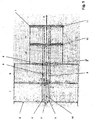
- FIG. 1 schematically the individual process steps for the production of a bag 1 according to the invention are shown.
- the numbers I, II, III and IV show different production states.
- a hole 3 is punched into the middle of the film.
- the flat web 2 is a plastic film or a paper web or a single-sided or double-sided coated paper web.
- a cutout in the form of a punched-in piece 6, 7 is introduced into the protective strip with the exact rapport.
- Rapport exact here means that the punches 6, 7 are introduced exactly matching the width of the finished bag in the protective strip.
- the glue trace is 4, 5 applied to the web 2 and the hole 3 punched.
- the protective strip 8, 9 provided with the recess 6, 7 is applied to the adhesive strip.
- the recess 6, 7 is in the rough schematic representation of the process steps a Tell the glue track 4, 5 free.
- Process step III shows the flat web 2 folded on both sides, so that a front wall and a rear wall are formed.
- the front wall here is the side folded onto the flat web. It can be clearly seen that a portion of the adhesive strip 4, 5 is exposed through the recess 6, 7, so that a introduced in step IV weld to form the rare welds 10, 11 extends into the region of the adhesive strip 4, 5.
- the flat web 2 is formed from a paper web, then at least the opposite sides of the front wall and rear wall are coated with a thermoplastic material, so that a welding of the side walls 6, 7 is made possible.
- the arrow P indicates the production direction. Finally, there is a longitudinal and transverse cutting of the welded Follenbahn 2 to form the bag according to the invention.
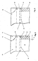
- FIG. 2 shows a plan view of a front side of a packaging bag 1 with an arcuate recess 12 in the protective strip 13.
- a hole 16 is punched, which makes it possible to easily grab the protective strip 13 and to release from the located on the rear wall 14 Glue trace 16 ,
- the front wall 17 covers the rear wall 14 completely in this embodiment. That is, the flat sheet 2 has been folded up to its center line 18.
- FIG. 5 is shown in principle.
- FIG. 3 is a linear formation of the recess 22 in the protective strip 23 is introduced. It should be noted here that any geometric shape is conceivable, which provides the protective strip with a recess, wherein it is essential that the protective strip 8, 9, 13, 23 is recessed such that the weld 10, 11, 19, 24 to reaches the adhesive strip 4, 5, 16, 25, so that the overlap region 11 is welded.
- FIG. 4 An advantageous embodiment of a bag 40 according to the invention is in the FIG. 4 played.
- the recess 26 which, as already described, have any shapes or even can approach their entire width B to the adhesive strip 27, it is inventively possible to form the recess 26 so that the charring 28 into the area of the adhesive strip 27 extends.
- the recess 26 in this case has a circular segment-like shape.
- the circular segment-like shape 26 is achieved by a circular section-shaped stamping in the protective strip 29 before the feeding and sticking to the adhesive strip 27.
- FIG. 5 is a combination of linear sections 31, 32 introduced as a recess in the protective strip 33.
- the dashed line 34 indicates in principle that such a cut can also extend into the region of the adhesive strip 35.
- the adhesive strip 35 has a width of 6 to 8 mm and extends over the entire bag width. According to the invention, it is conceivable to extend the adhesive strip 4, 5, 16, 25, 27, 35 into a region of approximately 2 mm from the weld seam 10, 11, 28, 36 into a region of approximately 2 mm in the adhesive strip.
- the bag 50 according to the invention according to the FIG. 5 has a front wall 37 and a rear wall 38.
- the front wall 37 does not completely cover the rear wall 38.
- a protective strip 33 a paper strip 33 is used as a protective strip 33.
- the protective strip 33 isolates the opposing inner sides of the front wall 37 and rear wall 38 against each other, so that a welding of the front wall 37 and rear wall 38 is prevented.
- the packaging bag 1, 40, 50 is used for the packaging of food and here of fish.
- the disadvantage of ice-cooled fish is that the ice adhering to the fish in the package 1, 40, 50 melts and the molten ice may emerge as water from the packaging means 1, 40, 50.
- the packaging bag 1, 40, 50 according to the invention closes the food liquid-tight so that no liquid can escape.
Landscapes
- Engineering & Computer Science (AREA)
- Mechanical Engineering (AREA)
- Bag Frames (AREA)
Description
- Die Erfindung betrifft einen Beutel, insbesondere einen Verpackungsbeutel für Lebensmittel, mit einer Vorderwand und einer Rückwand und einem auf mindestens einer Innenseite der Vorderwand oder Rückwand aufgebrachten Klebestreifen, wobei der Klebestreifen im unverechlossenen Zustand des Beutels mit einem Schutzstreifen abgedeckt ist und Seitenschweißnähten, die sich von einem unteren Ende des Beutels bis an den Schutzstreifen heran erstrecken, und mit den weiteren Merkmalen des Oberbegriffs des Anspruchs 1.
- In vielen Bereichen des täglichen Lebens werden Beutel zum Verpacken von Gütern eingesetzt. Je nach verpacktem Gut werden hierbei unterschiedliche Anforderungen an die Beutel gestellt. Wesentlich für den Transport ist hierbei der Verschluss des Beutels. Die Erfindung bezieht sich auf Beutel, die mit einem Klebestreifen versehen sind, so dass die Beutelwände zum Verschließen einer Einfüllöffnung des Beutels mit einander verklebbar sind. Zur Lagerung und zur leichteren Handhabung der Beutel sind die Klebestreifen zumeist mit einem Schutzstreifen versehen, der vor dem Verkleben der Wände oder Klebestreifen miteinander entfernt wird. Je nach Einsatzzweck und Verwendung der Verpackungsbeutel bestehen die Beutel aus Kunststoff, Papier oder aus mit Kunststoff beschichtetem Papier.
- Ein mittels eines Klebestreifens verschließbarer Beutel ist in der
DE 29 37 240 A1 beschrieben. Der Beutel besteht aus Kunststoff und wird aus einer Vorderwand und einer Rückwand gebildet, wobei die Faltlinie außermittig liegt, so dass die Rückwand länger ausgebildet ist als die Vorderwand. Die überstehende Rückwand bildet hierbei die Verschlusskappe des Beutels, wobei auf die Innenseite der Rückwand und auf der Vorderseite der Vorderwand ein Klebestreifen aufgebracht ist, die beide mit einer Schutzfolie versehen sind. Nach dem Entfernen der Schutzfolie ist die aus der Rückwand gebildete Klappe gegen die Vorderseite der Vorderwand zum Verschließen des Beutels klappbar. - Ein weiterer Beutel ist In der
GB 2 146 997 A - Ein Problem, das sich bei derartigen Beuteln ergibt, ist das, dass die Beutel zwar ein sicheres Verpacken und Transportieren des eingebrachten Gutes ermöglichen, die Beutel das verpackte Gut aber nicht flüssigkeitsdicht transportieren können. Insbesondere in den Fällen, In denen in den Beuteln zum Beispiel Lebensmittel transportiert oder verpackt werden ist es möglich, dass, zum Beispiel bei Gefrierprodukten Wasser im Beutel vorhanden ist. In diesem Fall ist es notwendig, dass der Beutel flüsslgkeltadicht verschließbar ist. Gemäß der
GB 2 146 997 A - Aus der
US 5,045,040 A ist ein Beutel gemäß dem Oberbegriff des Anspruchs 1 sowie eine Methode zur Herstellung von Umschlägen aus thermoplastischem Material bekannt, die einen mittels Schutzstreifen geschützten Klebestreifen aufweisen und bei denen die Beutelseiten mittels einer Schweißnaht verschweißt sind, wobei der Schutzstreifen im Bereich der Schweißnähte eine Aussparung aufweist. Mittels der Aussparung werden die Schweißnähte vollständig durch den Klebestreifen hindurchgeschweißt. - Aufgabe der Erfindung ist es, einen Beutel zu entwickeln, der das Verpackungsgut flüssigkeitsdicht einschließt und der darüber hinaus mit geringen konstruktiven Mitteln und kostengünstig herstellbar ist.
- Diese Aufgabe wird durch einen Beutel gemäß Anspruch 1 gelöst. Durch die erfindungsgemäβe Ausbildung des Schutzstreifens ist nun die Möglichkeit geschaffen, ein Verpackungsgut mit einem mit einem Klebestreifen versehenen Verpackungsbeutel flüssigkeitsdicht einzuschließen. Der aus dem Stand der Technik bekannte Nachteil, dass der Schutzstreifen über den Klebestreifen hinausragt und somit ein vollständiges Verschließen eines Verpackungsbeutels verhindert, ist somit überwunden. Der Schutzstreifen, der zum Beispiel ein Papierstreifen ist, besitzt eine Aussparung, die sich etwa aus einem mittleren Bereich der Schweißnaht heraus In Richtung des Klebestreifens und In Richtung des seitlichen Rands des Beutels erstreckt. Die Seitenschweißnähte reichen somit zumindest bis an den Klebestreifen heran, so dass nach einem Abziehen des Schutzstreifens der Beutel lückenlos mittels eines Zusammenfügens der Vorderseite und der Rückseite des Beutels flüssigkeitsdicht verschließbar ist. Die Aussparung im Schutzstreifen beginnt in einem mittleren Bereich der Schweißnähte und erstreckt sich linear und/oder mit bogenförmigen und/oder kreisförmigen Abschnitten in Richtung des seitlichen Endes des Beutels. Dies bietet einerseits den Vorteil, dass der Schutzstreifen leichter zwischen der Vorderwand und Rückwand des Beutels herausziehbar ist und andererseits den Vorteil, dass ein Öffnen des Beutels leichter möglich ist.
- Ein weiterer Vorteil ergibt sich erfindungsgemäß dadurch, dass sich die Schweißnähte bis in einen Bereich des Klebestreifens hineinerstrecken, das heißt, die Aussparung im Schutzβtrei fen legt einen Teil des Klebestreifens zum Verschweißen der Vorderwand und Rückwand frei. Hierdurch wird eine noch größere Sicherheit In Bezug auf das flüssigkeitsdichte Verschließen des Beutels erreicht.
- Nachfolgend wird die Erfindung anhand von Prinzipskizzen an Ausführungsbelspielen näher erläutert. Es zeigt:
- Figur 1
- Eine schematisch aneinander gereihte Abfolge des Ablaufs der ein- zelnen Fertigungsstufen zur Herstellung eines erfindungsgemäßen Beutels,
- Figur 2
- einen Eckbereich eines Beutels mit einer bogenförmigen Aussparung im Schutzstreifen,
- Figur 3
- einen Eckbereich eines Beutels mit einer linearen Aussparung im Schutzstreifen,
- Figur 4
- einen erfindungsgemäßen Beutel mit einer kreisabschnittsförmigen Aussparung im Schutzstreifen, die bis in den Bereich des Klebestrei- fens reicht und
- Figur 5
- einen erfindungsgemäßen Beutel mit einer weiteren geometrischen Form als Aussparung im Schutzstreifen, die bis an den Klebestreifen heranreicht und sich entlang des Klebestreifens erstreckt.
- In der
Figur 1 sind schematisch die einzelnen Verfahrensschritte zur Herstellung eines erfindungsgemäßen Beutels 1 wiedergegeben. Die Ziffern I, II, III und IV zeigen dabei unterschiedliche Fertigungszustände. Ausgehend von einer flachllegenden Folie 2 wird In die Mitte der Folie ein Loch 3 eingestanzt. Auf die mit dem Loch versehene Flachbahn 2 wird ein Klebestreifen 4, 5, die beispielsweise eine Leimspur ist, in einem separaten Verfahrensschritt aufgebracht. Die Flachbahn 2 ist eine Kunststofffolie oder eine Papierbahn oder eine einseitig oder beidseitig beschichtete Papierbahn. - Bevor in einem nächsten Verfehtensachritt der Schutzstreifen auf die Bahn 2 aufgebracht wird, wird rapportgenau eine Aussparung in Form einer Einstanzung 6, 7 in den Schutzstreifen eingebracht. Rapportgenau bedeutet hierbei, dass die Einstanzungen 6, 7 exakt passend zur Breite der fertigen Beutel in den Schutzstreifen eingebracht werden. In dem mit I bezeichneten Verfahrensschritt ist lediglich die Leimspur 4, 5 auf die Bahn 2 aufgetragen und das Loch 3 eingestanzt. In dem mit II bezifferten Verfahrensschritt ist der mit der Aussparung 6, 7 versehene Schutzstreifen 8, 9 auf den Klebestreifen aufgebracht. Die Aussparung 6, 7 liegt in der grobschematischen Darstellung der Verfahrensschritte einen Tell der Leimspur 4, 5 frei.
- Der Verfahrensschritt III zeigt die beidseitig zusammengefaltete Flachbahn 2, so dass eine Vorderwand und eine Rückwand gebildet ist. Als Vorderwand wird hierbei die auf die Flachbahn gefaltete Seite bezeichnet. Deutlich zu erkennen ist, dass durch die Aussparung 6, 7 ein Teil des Klebestreifens 4, 5 freigelegt wird, so dass eine im Verfahrensschritt IV eingebrachte Schweißnaht, zur Bildung der Seltenschweißnähte 10, 11 bis in den Bereich des Klebestreifens 4, 5 reicht. Wird die Flachbahn 2 aus einer Papierbahn gebildet, so sind zumindest die sich gegenüberliegenden Seiten der Vorderwand und Rückwand mit einem thermoplastischen Kunststoff beschichtet, so dass ein Verschweißen der Seitenwände 6, 7 ermöglicht wird.
- Der Pfeil P zeigt die Produktionsrichtung an. Abschließend erfolgt ein Längs- und Querschneiden der verschweißten Follenbahn 2 zur Bildung der erfindungsgemäßen Beutel.
- Die
Figur 2 zeigt eine Draufsicht auf eine Vorderseite eines Verpackungsbeutels 1 mit einer bogenförmigen Aussparung 12 im Schutzstreifen 13. In die Rückwand 14 ist ein Loch 16 eingestanzt, welches es ermöglicht, den Schutzstreifen 13 leicht zu ergreifen und von der auf der Rückwand 14 befindlichen Leimspur 16 zu lösen. Die Vorderwand 17 deckt in diesem Ausführungsbeispiel die Rückwand 14 vollständig ab. Das heißt, die Flachbahn 2 wurde bis zu ihrer Mittellinie 18 hin gefaltet. Es ist aber ebenfalls vorstellbar, die Faltung vor der Mittellinie 18 enden zu lassen, um ebenfalls die Vorderwand 17 leichter ergreifen und somit den Beutel leichter öffnen zu können, wie dies beispielhaft in einem weiteren Ausführungsbeispiel der Erfindung inFigur 5 prinzipiell dargestellt ist. - Die Verschweißung der Vorderwand und Rückwand reicht von einem Rand 21 des Beutels 20 bis in einen Bereich des Beutels 20 hinein. Eine übliche Breite B der Schweißnaht liegt bei circa 10 mm. Wie deutlich zu erkennen ist, überragt der Schutzstreifen 13 die Leimspur 16 in Richtung der Schweißnaht 19. Diese Überlappung 11 führt bei Beuteln gemäß dem Stand der Technik dazu, dass eine Lücke zwischen der Schweißnaht und dem Klebestreifen entsteht, so dass die herkömmlichen Beutel nicht flüssigkeitsdicht sind. Durch die in der
Figur 2 dargestellte bogenförmige Aussparung 12 im Schutzstreifen 13 reicht die Schweißnaht 19 bis an den Klebestreifen 16 heran und verschließt den Überlappungsbereich L zur Bildung eines flüssigkeltsdichten Beutels 20. - In der
Figur 3 ist eine lineare Ausbildung der Aussparung 22 im Schutzstreifen 23 eingebracht. Es sei hierbei darauf hingewiesen, dass jegliche geometrische Form denkbar ist, die den Schutzstreifen mit einer Aussparung versieht, wobei wesentlich ist, dass der Schutzstreifen 8, 9, 13, 23 derart ausgespart ist, dass die Schweißnaht 10, 11, 19, 24 bis an den Klebestreifen 4, 5, 16, 25 heranreicht, so dass der Überlappungsbereich 11 verschweißt ist. - Eine vorteilhafte Ausführungsform eines erfindungsgemäßen Beutels 40 ist in der
Figur 4 wiedergegeben. Unabhängig von der geometrischen Form der Aussparung 26, die wie bereits beschrieben beliebige Formen aufweisen oder auch Ober Ihre gesamte Breite B bis an den Klebestreifen 27 heranreichen kann, ist es erfindungsgemäß möglich, die Aussparung 26 so auszubilden, dass die Verschwelung 28 bis in den Bereich des Klebestreifens 27 hineinreicht. Die Aussparung 26 besitzt hierbei eine kreissegmentartige Form. Die kreissegmentartige Form 26 wird durch eine kreisabschnittsförmige Einstanzung in den Schutzstreifen 29 vor dem Zuführen und Aufkleben auf den Klebestreifen 27 erzielt. - In der
Figur 5 ist eine Kombination aus linearen Abschnitten 31, 32 als Aussparung in den Schutzstreifen 33 eingebracht. Die gestrichelte Linie 34 gibt prinzipiell an, dass eine derartige Ausstanzung auch bis in den Bereich des Klebestreifens 35 reichen kann. Der Klebestreifen 35 besitzt eine Breite von 6 bis 8 mm und erstreckt sich über die gesamte Beutelbreite. Erfindungsgemäß ist es vorstellbar, den Klebestreifen 4, 5, 16, 25, 27, 35 in einen Bereich von etwa 2 mm von der Schweißnaht 10, 11, 28, 36 in einen Bereich von circa 2 mm in den Klebestreifen hineinreichen zu lassen. - Der erfindungsgemäße Beutel 50 gemäß der
Figur 5 besitzt eine Vorderwand 37 und eine Rückwand 38. Die Vorderwand 37 überdeckt die Rückwand 38 nicht vollständig. Dies bietet den Vorteil, dass der Verpackungsbeutel 50 leichter zu öffnen ist. Es ist erfingdungsgemäß vorstellbar, den Bereich der Vorderwand 37 der über die Schweißnaht 36 sich hinaus erstreckt, gegen die Vorderwand umzuklappen, um somit ein noch leichteres Öffnen des Verpackungsbeutels zu erreichen und um gleichzeitig den Schutzstreifen 33 leichter vom Klebestreifen 35 lösen zu können. Als Schutzstreifen 33 wird ein Papierstreifen 33 verwendet. Der Schutzstreifen 33 isoliert die gegeneinanderliegenden Innenseiten der Vorderwand 37 und Rückwand 38 gegeneinander, so dass ein Verschweißen der Vorderwand 37 und Rückwand 38 verhindert wird. - In einer vorteilhaften Verwendung des erfindungsgemäßen Verpackungabeutels 1, 40, 50 wird der Verpackungsbeutel 1, 40, 50 für die Verpackung von Lebensmitteln und hier von Fisch verwendet. Zumeist in Eis gekühlter Fisch hat den Nachteil, dass das am Fisch haftende Eis in der Verpackung 1, 40, 50 schmilzt und das geschmolzene Eis als Wasser aus dem Verpackungsmittel 1, 40, 50 austreten könnte. Der erfindungsgemäße Verpackungsbeutel 1, 40, 50 verschließt das Lebensmittel flüssigkeltsdicht so dass keine Flüssigkeit austreten kann.
Claims (12)
- Beutel, insbesondere Verpackungsbeutel, mit einer Vorderwand (37) und einer Rückwand (38) und einem auf mindestens einer Innenseite der Vorderwand (37) oder Rückwand (38) aufgebrachten Klebestreifen (4, 5, 27, 35), wobei der Klebestreifen (4, 5, 27, 35) im unverschlossenen Zustand des Beutels (1, 40, 50) mit einem Schutzstreifen (8, 9, 29, 33) abgedeckt ist und Seitenschweißnähten (10, 11, 28, 36), die sich von einem unteren Ende des Beutels (1, 40, 50) zumindest bis an den Schutzstreifen (8, 9, 29, 33) heran erstrecken, wobei der Schutzstreifen (8, , 9 29, 33) den Klebestreifen (4, 5, 27, 35) in Richtung der Seitenschweißnähte (10, 11, 28, 36) überragt und eine sich bis in den Bereich des Klebestreifens (4, 5, 27, 35) hinein erstreckende Aussparung (8, 7, 26, 31, 32, 34) aufweist, wobei die Aussparung (6, 7, 26, 31, 32, 34) im Schutzstreifen (8, 9, 29, 33) einen Teil des Klebestreifens (4, 5, 27, 35) zum Verschweißen der Vorderwand (37) und Rückwand (38) freilegt, so dass die nach Aufbringen des Klebestreifens (4, 5, 27, 35) und des Schutzstreifens (8, 9, 29, 33) eingebrachten Seitenschweißnähte (10, 11, 28, 36) bis in den Bereich des Klebestreifens (4, 5, 27, 35) hinein reichen, dadurch gekennzeichnet, dass sich die Aussparung (6, 7, 26, 31, 32, 34) ausgehend von einem mittleren Bereich der Breite (B) einer Seitenschweißnaht (10, 11, 28, 36) zu einer Beutelseite (21) hin erstreckt, so dass eine Seitenschweißnahtverlängerung gebildet ist.
- Beutel nach Anspruch 1, dadurch gekennzeichnet, dass die Aussparung (6, 7, 26, 31, 32, 34) aus linearen und/oder bogenförmigen Abschnitten (6, 7, 26, 31, 32, 34) gebildet ist.
- Beutel nach Anspruch 1 oder Anspruch 2, dadurch gekennzeichnet dass die Seitenschweißnähte (10, 11, 26, 36) eine Breite B von etwa 10 mm aufweisen und sich bis an den Rand des Beutels (1, 40, 50) erstrecken.
- Beutel nach einem der Ansprüche 1 bis 3, dadurch gekennzeichnet, dass er Klebestreifen (4, 5, 27, 35) eine Leimspur ist und eine Breite von 6 mm bis 8 mm aufweist und sich über die gesamte Breite des Beutels (1, 40, 50) erstreckt.
- Beutel nach einem der Ansprüche 1 bis 4, dadurch gekennzeichnet, dass sich eine Seitenachweißnaht (10, 11, 28, 36) 2 mm weit in den Klebestreifen (4, 5, 27, 35) hinein erstreckt.
- Beutel nach einem der Ansprüche 1 bis 5, dadurch gekennzeichnet, dass der Schutzstreifen (8, 9, 29, 33) ein Papierstreifen ist.
- Beutel nach einem der Ansprüche 1 bis 6, dadurch gekennzeichnet, dass der Beutel (1, 40, 50) ein Papierbeutel ist, der zumindest auf der innenseite der Vorderwand (37) und der Rückwand (38) mit einem thermoplastischen Kunststoff beschichtet ist.
- Beutel nach Anspruch 7, dadurch gekennzeichnet, dass die Vorderwand (37) und die Rückwand (38) beidseitig mit einem thermoplastischen Kunststoff beschichtet sind.
- Beutel nach einem der Ansprüche 1 bis 8, dadurch gekennzeichnet, dass die Vorderwand (37) eine geringere Länge aufweist, ein die Rückwand (38), dass der Klebestreifen (4, 5, 27, 35) auf die innenseite der Rückwand (38) aufgebracht ist, und dass der sich über die Schweißnaht (36) hinaus erstreckende Bereich der Vorderrand (37) gegen die Außenseite der Vorderwand (37) gefaltet ist, so dass der Schutzstreifen (8, 9, 29, 33) greifbar ist.
- Beutel nach einem der Ansprüche 1 bis 9, dadurch gekennzeichnet, dass der Beutel (1, 40, 50) einteilig und aus einer gefalteten Papierbahn (2) gebildet ist.
- Beutel nach einem der Ansprüche 1 bis 10, dadurch gekennzeichnet, dass der Beutel (1, 40, 50) eine Verpackung für Lebensmittel, insbesondere für Fisch, ist.
- Verwendung eines Beutels (1, 40, 50) gemäß einem der Ansprüche 1 bis 11 als flüssigkeitsdichte Lebenemittelverpackung.
Applications Claiming Priority (1)
| Application Number | Priority Date | Filing Date | Title |
|---|---|---|---|
| DE102008032582 | 2008-07-11 |
Publications (2)
| Publication Number | Publication Date |
|---|---|
| EP2143654A1 EP2143654A1 (de) | 2010-01-13 |
| EP2143654B1 true EP2143654B1 (de) | 2012-06-27 |
Family
ID=41027504
Family Applications (1)
| Application Number | Title | Priority Date | Filing Date |
|---|---|---|---|
| EP20090009068 Not-in-force EP2143654B1 (de) | 2008-07-11 | 2009-07-10 | Verpackungsbeutel |
Country Status (2)
| Country | Link |
|---|---|
| EP (1) | EP2143654B1 (de) |
| DE (1) | DE102009032807A1 (de) |
Family Cites Families (8)
| Publication number | Priority date | Publication date | Assignee | Title |
|---|---|---|---|---|
| GB245997A (en) | 1925-05-11 | 1926-01-21 | Yoshitoshi Noishiki | An electrical instrument for medical treatment |
| NL7906788A (nl) | 1978-09-29 | 1980-04-01 | Franko Plastics Ltd | Zak. |
| GB2145997B (en) | 1983-09-02 | 1986-12-31 | Interpoly Ltd | Tamperproof bag |
| US5045040A (en) * | 1988-04-28 | 1991-09-03 | Uniflex, Inc. | Envelope closure seal and method |
| US6012844A (en) * | 1999-02-16 | 2000-01-11 | Huseman; David C. | Selectively closeable plastic film bag |
| US20040105600A1 (en) * | 2002-11-25 | 2004-06-03 | Floyd Thomas M | Multi-wall bag |
| FR2885353B1 (fr) * | 2005-05-04 | 2010-03-05 | Decomatic Sa | Enveloppe etanche en matiere plastique |
| FR2908745B1 (fr) * | 2006-11-16 | 2009-02-06 | Alpem Soc Par Actions Simplifi | Sachet d'emballage preforme, notamment pour des produits alimentaires. |
-
2009
- 2009-07-10 DE DE102009032807A patent/DE102009032807A1/de not_active Withdrawn
- 2009-07-10 EP EP20090009068 patent/EP2143654B1/de not_active Not-in-force
Also Published As
| Publication number | Publication date |
|---|---|
| DE102009032807A1 (de) | 2010-03-11 |
| EP2143654A1 (de) | 2010-01-13 |
Similar Documents
| Publication | Publication Date | Title |
|---|---|---|
| EP0577615B1 (de) | Schlauchbeutelverpackung | |
| EP2039620B1 (de) | Seitenfaltenbeutel | |
| DE2758092A1 (de) | Oeffnungsvorrichtung fuer eine verpackung aus flexiblem material | |
| EP0363693A1 (de) | Verpackung aus Verbundfolie sowie Verfahren zum Herstellen derselben | |
| DE1908851A1 (de) | Verpackung mit leicht zu oeffnendem Verschluss | |
| EP2347972B1 (de) | Wiederverschliessbare Verpackung | |
| EP2508445A1 (de) | Verpackungsbeutel mit Aufreissverschluss | |
| CH620651A5 (de) | ||
| DE102016102691A1 (de) | Folienverpackung sowie Verfahren zum Verpacken eines Produktes in einer Folienverpackung | |
| EP0244674A2 (de) | Flüssigkeitspackung, Herstellung derselben und Kunststoffbahn zur Herstellung der Flüssigkeitspackung | |
| WO2010121731A1 (de) | Schlauchbeutelverpackung sowie verfahren zu ihrem öffnen und zu ihrer herstellung | |
| DE202004012301U1 (de) | Wiederverschließbarer Schlauchbeutel | |
| DE60000086T2 (de) | Verpackung für Lebensmittel, Zuschnitt und Verfahren zu seiner Herstellung | |
| DE102013110994A1 (de) | Folienverpackungsbeutel sowie Verfahren zur Herstellung des Folienverpackungsbeutels | |
| DE3115144A1 (de) | Verpackungsfolie, insbesondere fuer nahrungsmittel | |
| EP2567907A1 (de) | Tabakbeutel | |
| DE102009046507A1 (de) | Wiederverschließbare Verpackung mit Doppelklebstelle | |
| EP2361842B1 (de) | Beutel aus Kunststofffolie | |
| DE102011075481A1 (de) | Verbundfolie für Verpackungsbehälter, Verfahren zum Herstellen einer Verbundfolie sowie Verpackungsbehälter | |
| EP2284091B1 (de) | Seitenfaltenbeutel aus einer Kunststofffolie | |
| DE2734250C2 (de) | Flüssigkeitsverpackung mit Aufreißöffnung | |
| EP2143654A1 (de) | Verpackungsbeutel | |
| AT508995B1 (de) | Wiederverschliessbare verpackung | |
| DE3644618A1 (de) | Tragbarer verpackungsbeutel aus kunststoffolie mit einstueckig angeformtem griffteil | |
| DE102009014245A1 (de) | Schlauchbeutelverpackung, Lebensmittelprodukt und Verfahren zur Herstellung davon |
Legal Events
| Date | Code | Title | Description |
|---|---|---|---|
| PUAI | Public reference made under article 153(3) epc to a published international application that has entered the european phase |
Free format text: ORIGINAL CODE: 0009012 |
|
| AK | Designated contracting states |
Kind code of ref document: A1 Designated state(s): AT BE BG CH CY CZ DE DK EE ES FI FR GB GR HR HU IE IS IT LI LT LU LV MC MK MT NL NO PL PT RO SE SI SK SM TR |
|
| 17P | Request for examination filed |
Effective date: 20100226 |
|
| 17Q | First examination report despatched |
Effective date: 20100512 |
|
| GRAP | Despatch of communication of intention to grant a patent |
Free format text: ORIGINAL CODE: EPIDOSNIGR1 |
|
| GRAS | Grant fee paid |
Free format text: ORIGINAL CODE: EPIDOSNIGR3 |
|
| GRAA | (expected) grant |
Free format text: ORIGINAL CODE: 0009210 |
|
| AK | Designated contracting states |
Kind code of ref document: B1 Designated state(s): AT BE BG CH CY CZ DE DK EE ES FI FR GB GR HR HU IE IS IT LI LT LU LV MC MK MT NL NO PL PT RO SE SI SK SM TR |
|
| REG | Reference to a national code |
Ref country code: GB Ref legal event code: FG4D Free format text: NOT ENGLISH |
|
| REG | Reference to a national code |
Ref country code: CH Ref legal event code: EP |
|
| REG | Reference to a national code |
Ref country code: AT Ref legal event code: REF Ref document number: 564059 Country of ref document: AT Kind code of ref document: T Effective date: 20120715 |
|
| REG | Reference to a national code |
Ref country code: IE Ref legal event code: FG4D Free format text: LANGUAGE OF EP DOCUMENT: GERMAN |
|
| REG | Reference to a national code |
Ref country code: DE Ref legal event code: R096 Ref document number: 502009003905 Country of ref document: DE Effective date: 20120823 |
|
| PG25 | Lapsed in a contracting state [announced via postgrant information from national office to epo] |
Ref country code: NO Free format text: LAPSE BECAUSE OF FAILURE TO SUBMIT A TRANSLATION OF THE DESCRIPTION OR TO PAY THE FEE WITHIN THE PRESCRIBED TIME-LIMIT Effective date: 20120927 Ref country code: LT Free format text: LAPSE BECAUSE OF FAILURE TO SUBMIT A TRANSLATION OF THE DESCRIPTION OR TO PAY THE FEE WITHIN THE PRESCRIBED TIME-LIMIT Effective date: 20120627 Ref country code: SE Free format text: LAPSE BECAUSE OF FAILURE TO SUBMIT A TRANSLATION OF THE DESCRIPTION OR TO PAY THE FEE WITHIN THE PRESCRIBED TIME-LIMIT Effective date: 20120627 Ref country code: FI Free format text: LAPSE BECAUSE OF FAILURE TO SUBMIT A TRANSLATION OF THE DESCRIPTION OR TO PAY THE FEE WITHIN THE PRESCRIBED TIME-LIMIT Effective date: 20120627 |
|
| REG | Reference to a national code |
Ref country code: NL Ref legal event code: VDEP Effective date: 20120627 |
|
| REG | Reference to a national code |
Ref country code: LT Ref legal event code: MG4D Effective date: 20120627 |
|
| PG25 | Lapsed in a contracting state [announced via postgrant information from national office to epo] |
Ref country code: HR Free format text: LAPSE BECAUSE OF FAILURE TO SUBMIT A TRANSLATION OF THE DESCRIPTION OR TO PAY THE FEE WITHIN THE PRESCRIBED TIME-LIMIT Effective date: 20120627 Ref country code: GR Free format text: LAPSE BECAUSE OF FAILURE TO SUBMIT A TRANSLATION OF THE DESCRIPTION OR TO PAY THE FEE WITHIN THE PRESCRIBED TIME-LIMIT Effective date: 20120928 Ref country code: SI Free format text: LAPSE BECAUSE OF FAILURE TO SUBMIT A TRANSLATION OF THE DESCRIPTION OR TO PAY THE FEE WITHIN THE PRESCRIBED TIME-LIMIT Effective date: 20120627 Ref country code: LV Free format text: LAPSE BECAUSE OF FAILURE TO SUBMIT A TRANSLATION OF THE DESCRIPTION OR TO PAY THE FEE WITHIN THE PRESCRIBED TIME-LIMIT Effective date: 20120627 |
|
| PG25 | Lapsed in a contracting state [announced via postgrant information from national office to epo] |
Ref country code: CZ Free format text: LAPSE BECAUSE OF FAILURE TO SUBMIT A TRANSLATION OF THE DESCRIPTION OR TO PAY THE FEE WITHIN THE PRESCRIBED TIME-LIMIT Effective date: 20120627 Ref country code: SK Free format text: LAPSE BECAUSE OF FAILURE TO SUBMIT A TRANSLATION OF THE DESCRIPTION OR TO PAY THE FEE WITHIN THE PRESCRIBED TIME-LIMIT Effective date: 20120627 Ref country code: IS Free format text: LAPSE BECAUSE OF FAILURE TO SUBMIT A TRANSLATION OF THE DESCRIPTION OR TO PAY THE FEE WITHIN THE PRESCRIBED TIME-LIMIT Effective date: 20121027 Ref country code: EE Free format text: LAPSE BECAUSE OF FAILURE TO SUBMIT A TRANSLATION OF THE DESCRIPTION OR TO PAY THE FEE WITHIN THE PRESCRIBED TIME-LIMIT Effective date: 20120627 Ref country code: RO Free format text: LAPSE BECAUSE OF FAILURE TO SUBMIT A TRANSLATION OF THE DESCRIPTION OR TO PAY THE FEE WITHIN THE PRESCRIBED TIME-LIMIT Effective date: 20120627 Ref country code: CY Free format text: LAPSE BECAUSE OF FAILURE TO SUBMIT A TRANSLATION OF THE DESCRIPTION OR TO PAY THE FEE WITHIN THE PRESCRIBED TIME-LIMIT Effective date: 20120627 |
|
| PG25 | Lapsed in a contracting state [announced via postgrant information from national office to epo] |
Ref country code: PT Free format text: LAPSE BECAUSE OF FAILURE TO SUBMIT A TRANSLATION OF THE DESCRIPTION OR TO PAY THE FEE WITHIN THE PRESCRIBED TIME-LIMIT Effective date: 20121029 Ref country code: PL Free format text: LAPSE BECAUSE OF FAILURE TO SUBMIT A TRANSLATION OF THE DESCRIPTION OR TO PAY THE FEE WITHIN THE PRESCRIBED TIME-LIMIT Effective date: 20120627 Ref country code: MC Free format text: LAPSE BECAUSE OF NON-PAYMENT OF DUE FEES Effective date: 20120731 Ref country code: MK Free format text: LAPSE BECAUSE OF FAILURE TO SUBMIT A TRANSLATION OF THE DESCRIPTION OR TO PAY THE FEE WITHIN THE PRESCRIBED TIME-LIMIT Effective date: 20120627 Ref country code: IT Free format text: LAPSE BECAUSE OF FAILURE TO SUBMIT A TRANSLATION OF THE DESCRIPTION OR TO PAY THE FEE WITHIN THE PRESCRIBED TIME-LIMIT Effective date: 20120627 |
|
| PG25 | Lapsed in a contracting state [announced via postgrant information from national office to epo] |
Ref country code: NL Free format text: LAPSE BECAUSE OF FAILURE TO SUBMIT A TRANSLATION OF THE DESCRIPTION OR TO PAY THE FEE WITHIN THE PRESCRIBED TIME-LIMIT Effective date: 20120627 |
|
| PG25 | Lapsed in a contracting state [announced via postgrant information from national office to epo] |
Ref country code: ES Free format text: LAPSE BECAUSE OF FAILURE TO SUBMIT A TRANSLATION OF THE DESCRIPTION OR TO PAY THE FEE WITHIN THE PRESCRIBED TIME-LIMIT Effective date: 20121008 Ref country code: DK Free format text: LAPSE BECAUSE OF FAILURE TO SUBMIT A TRANSLATION OF THE DESCRIPTION OR TO PAY THE FEE WITHIN THE PRESCRIBED TIME-LIMIT Effective date: 20120627 |
|
| PLBE | No opposition filed within time limit |
Free format text: ORIGINAL CODE: 0009261 |
|
| STAA | Information on the status of an ep patent application or granted ep patent |
Free format text: STATUS: NO OPPOSITION FILED WITHIN TIME LIMIT |
|
| REG | Reference to a national code |
Ref country code: IE Ref legal event code: MM4A |
|
| 26N | No opposition filed |
Effective date: 20130328 |
|
| REG | Reference to a national code |
Ref country code: DE Ref legal event code: R097 Ref document number: 502009003905 Country of ref document: DE Effective date: 20130328 |
|
| PG25 | Lapsed in a contracting state [announced via postgrant information from national office to epo] |
Ref country code: MT Free format text: LAPSE BECAUSE OF FAILURE TO SUBMIT A TRANSLATION OF THE DESCRIPTION OR TO PAY THE FEE WITHIN THE PRESCRIBED TIME-LIMIT Effective date: 20120627 Ref country code: IE Free format text: LAPSE BECAUSE OF NON-PAYMENT OF DUE FEES Effective date: 20120710 Ref country code: BG Free format text: LAPSE BECAUSE OF FAILURE TO SUBMIT A TRANSLATION OF THE DESCRIPTION OR TO PAY THE FEE WITHIN THE PRESCRIBED TIME-LIMIT Effective date: 20120927 |
|
| PGFP | Annual fee paid to national office [announced via postgrant information from national office to epo] |
Ref country code: BE Payment date: 20130719 Year of fee payment: 5 Ref country code: DE Payment date: 20130722 Year of fee payment: 5 |
|
| PGFP | Annual fee paid to national office [announced via postgrant information from national office to epo] |
Ref country code: GB Payment date: 20130719 Year of fee payment: 5 Ref country code: FR Payment date: 20130722 Year of fee payment: 5 |
|
| REG | Reference to a national code |
Ref country code: CH Ref legal event code: PL |
|
| PG25 | Lapsed in a contracting state [announced via postgrant information from national office to epo] |
Ref country code: CH Free format text: LAPSE BECAUSE OF NON-PAYMENT OF DUE FEES Effective date: 20130731 Ref country code: LI Free format text: LAPSE BECAUSE OF NON-PAYMENT OF DUE FEES Effective date: 20130731 Ref country code: TR Free format text: LAPSE BECAUSE OF FAILURE TO SUBMIT A TRANSLATION OF THE DESCRIPTION OR TO PAY THE FEE WITHIN THE PRESCRIBED TIME-LIMIT Effective date: 20120627 |
|
| PG25 | Lapsed in a contracting state [announced via postgrant information from national office to epo] |
Ref country code: SM Free format text: LAPSE BECAUSE OF FAILURE TO SUBMIT A TRANSLATION OF THE DESCRIPTION OR TO PAY THE FEE WITHIN THE PRESCRIBED TIME-LIMIT Effective date: 20120627 Ref country code: LU Free format text: LAPSE BECAUSE OF NON-PAYMENT OF DUE FEES Effective date: 20120710 |
|
| PG25 | Lapsed in a contracting state [announced via postgrant information from national office to epo] |
Ref country code: HU Free format text: LAPSE BECAUSE OF FAILURE TO SUBMIT A TRANSLATION OF THE DESCRIPTION OR TO PAY THE FEE WITHIN THE PRESCRIBED TIME-LIMIT Effective date: 20090710 |
|
| REG | Reference to a national code |
Ref country code: DE Ref legal event code: R119 Ref document number: 502009003905 Country of ref document: DE |
|
| GBPC | Gb: european patent ceased through non-payment of renewal fee |
Effective date: 20140710 |
|
| REG | Reference to a national code |
Ref country code: FR Ref legal event code: ST Effective date: 20150331 |
|
| PG25 | Lapsed in a contracting state [announced via postgrant information from national office to epo] |
Ref country code: DE Free format text: LAPSE BECAUSE OF NON-PAYMENT OF DUE FEES Effective date: 20150203 |
|
| REG | Reference to a national code |
Ref country code: DE Ref legal event code: R119 Ref document number: 502009003905 Country of ref document: DE Effective date: 20150203 |
|
| PG25 | Lapsed in a contracting state [announced via postgrant information from national office to epo] |
Ref country code: GB Free format text: LAPSE BECAUSE OF NON-PAYMENT OF DUE FEES Effective date: 20140710 Ref country code: FR Free format text: LAPSE BECAUSE OF NON-PAYMENT OF DUE FEES Effective date: 20140731 |
|
| REG | Reference to a national code |
Ref country code: AT Ref legal event code: MM01 Ref document number: 564059 Country of ref document: AT Kind code of ref document: T Effective date: 20140710 |
|
| PG25 | Lapsed in a contracting state [announced via postgrant information from national office to epo] |
Ref country code: AT Free format text: LAPSE BECAUSE OF NON-PAYMENT OF DUE FEES Effective date: 20140710 |
|
| PG25 | Lapsed in a contracting state [announced via postgrant information from national office to epo] |
Ref country code: BE Free format text: LAPSE BECAUSE OF NON-PAYMENT OF DUE FEES Effective date: 20140731 |