EP0244674A2 - Flüssigkeitspackung, Herstellung derselben und Kunststoffbahn zur Herstellung der Flüssigkeitspackung - Google Patents
Flüssigkeitspackung, Herstellung derselben und Kunststoffbahn zur Herstellung der Flüssigkeitspackung Download PDFInfo
- Publication number
- EP0244674A2 EP0244674A2 EP87105546A EP87105546A EP0244674A2 EP 0244674 A2 EP0244674 A2 EP 0244674A2 EP 87105546 A EP87105546 A EP 87105546A EP 87105546 A EP87105546 A EP 87105546A EP 0244674 A2 EP0244674 A2 EP 0244674A2
- Authority
- EP
- European Patent Office
- Prior art keywords
- layer
- strip
- opening
- opening strip
- double
- Prior art date
- Legal status (The legal status is an assumption and is not a legal conclusion. Google has not performed a legal analysis and makes no representation as to the accuracy of the status listed.)
- Granted
Links
Images


Classifications
-
- B—PERFORMING OPERATIONS; TRANSPORTING
- B65—CONVEYING; PACKING; STORING; HANDLING THIN OR FILAMENTARY MATERIAL
- B65D—CONTAINERS FOR STORAGE OR TRANSPORT OF ARTICLES OR MATERIALS, e.g. BAGS, BARRELS, BOTTLES, BOXES, CANS, CARTONS, CRATES, DRUMS, JARS, TANKS, HOPPERS, FORWARDING CONTAINERS; ACCESSORIES, CLOSURES, OR FITTINGS THEREFOR; PACKAGING ELEMENTS; PACKAGES
- B65D77/00—Packages formed by enclosing articles or materials in preformed containers, e.g. boxes, cartons, sacks or bags
- B65D77/22—Details
- B65D77/30—Opening or contents-removing devices added or incorporated during filling or closing of containers
- B65D77/32—Tearing-strings or like flexible elements
- B65D77/34—Tearing-strings or like flexible elements enclosed in a mouth seal
-
- B—PERFORMING OPERATIONS; TRANSPORTING
- B65—CONVEYING; PACKING; STORING; HANDLING THIN OR FILAMENTARY MATERIAL
- B65D—CONTAINERS FOR STORAGE OR TRANSPORT OF ARTICLES OR MATERIALS, e.g. BAGS, BARRELS, BOTTLES, BOXES, CANS, CARTONS, CRATES, DRUMS, JARS, TANKS, HOPPERS, FORWARDING CONTAINERS; ACCESSORIES, CLOSURES, OR FITTINGS THEREFOR; PACKAGING ELEMENTS; PACKAGES
- B65D5/00—Rigid or semi-rigid containers of polygonal cross-section, e.g. boxes, cartons or trays, formed by folding or erecting one or more blanks made of paper
- B65D5/42—Details of containers or of foldable or erectable container blanks
- B65D5/72—Contents-dispensing means
- B65D5/74—Spouts
- B65D5/741—Spouts for containers having a tubular body
- B65D5/742—Spouts formed by deforming or tearing the closure flaps or severed or incised parts of the closure flaps
-
- Y—GENERAL TAGGING OF NEW TECHNOLOGICAL DEVELOPMENTS; GENERAL TAGGING OF CROSS-SECTIONAL TECHNOLOGIES SPANNING OVER SEVERAL SECTIONS OF THE IPC; TECHNICAL SUBJECTS COVERED BY FORMER USPC CROSS-REFERENCE ART COLLECTIONS [XRACs] AND DIGESTS
- Y10—TECHNICAL SUBJECTS COVERED BY FORMER USPC
- Y10S—TECHNICAL SUBJECTS COVERED BY FORMER USPC CROSS-REFERENCE ART COLLECTIONS [XRACs] AND DIGESTS
- Y10S428/00—Stock material or miscellaneous articles
- Y10S428/91—Product with molecular orientation
-
- Y—GENERAL TAGGING OF NEW TECHNOLOGICAL DEVELOPMENTS; GENERAL TAGGING OF CROSS-SECTIONAL TECHNOLOGIES SPANNING OVER SEVERAL SECTIONS OF THE IPC; TECHNICAL SUBJECTS COVERED BY FORMER USPC CROSS-REFERENCE ART COLLECTIONS [XRACs] AND DIGESTS
- Y10—TECHNICAL SUBJECTS COVERED BY FORMER USPC
- Y10T—TECHNICAL SUBJECTS COVERED BY FORMER US CLASSIFICATION
- Y10T428/00—Stock material or miscellaneous articles
- Y10T428/31504—Composite [nonstructural laminate]
- Y10T428/31786—Of polyester [e.g., alkyd, etc.]
- Y10T428/31797—Next to addition polymer from unsaturated monomers
Definitions
- the invention relates to a pack for liquids made of plastic-coated cardboard carrier material, with a longitudinal weld seam and at least one transverse weld seam lying in a double cardboard strip on the top of the pack, in which an opening device is arranged in the form of a double-layered, one-sided sealed opening strip, the outer sides of which are arranged with the inside of the double cardboard strip and which is made of a laminated plastic, one layer of which is aligned in one direction.
- Liquid packs made of plastic, paper, cardboard or the like are known, for example in parallelepiped form. With such Liquid packs have longitudinal weld seams that extend over the height of the standing parallelepiped pack, and transverse weld seams in the bottom and / or top wall area of the pack.
- the usual parallelepipedic liquid pack has at least in the upper area on opposite sides two triangular lobes, and the double cardboard strip mentioned at the beginning extends in this known pack from the tip of one triangular tab to the tip of the opposite other triangular tab.
- a known opening device consists of a piece of hose made of laminated plastic, the hose axis running parallel to the longitudinal weld seam and consequently transverse to the transverse weld seam.
- one layer is oriented or oriented in the tear direction, and on this layer, where the connection with the double cardboard strip has to be created, a better sealable plastic layer is laminated on. So that the plastic tube part serving as the opening device can be closed, either the tube must protrude upwards out of the double cardboard strip of the liquid pack, resulting in the disadvantage that such a liquid pack cannot be produced by the hose.
- the hose must be weldable on its side facing the inside of the pack, which is why the areas with lower sealability must be arranged in a special way, preferably protruding downwards towards the inside of the pack.
- This has the disadvantage that, on the one hand, externally accessible pockets are formed within the hose section with the associated hygiene problems and, on the other hand, a complicated manufacture of the hose section renders the installation of such an opening device uneconomical.
- the invention is therefore based on the object of creating a pack for liquids of the type specified at the outset, the production of which from a hose enables the end user to understand the tearing action with a simple and inexpensive to produce opening device with good hygiene properties.
- the opening strip is U-shaped in cross section and is arranged such that the free ends of the legs of the U are directed towards the inside of the package, the legs of the U only at the beginning and end of the opening strip an initial and an end sealing area are welded together, the initial sealing area provides for a first part a gripping flap protruding from the double cardboard strip and the other second part is sealed in the double cardboard strip in the area of the intersecting longitudinal and transverse weld seam and that the end sealing area in the pouring area of the Opening device is sealed in the double cardboard strip.
- the novel design and arrangement of the opening strip according to the invention advantageously eliminates the formation of pockets which are accessible from the outside and in which contaminants can collect.
- the initial seal area gets its name because the end user starts the tearing process here. Only part of this area forms the gripping tab, the other second part forms the front closure, while the end sealing area forms the rear closure of the opening strip with the double cardboard strip. Above, i.e. to the outside, the opening strip - via its connecting web - is closed.
- the end seal area does not have to be arranged exactly at the tip of the pouring end, i.e. in the tip of the doubled triangular flap, of a parallelepipedic packing; if desired, the opening strip with the end seal area can be folded over beyond the point of the pouring tip so that it is still in the Pouring area remains.
- the opening strip can thereby be made shorter or longer, and the attachment and fixing of the opening strip to the material web can be influenced, for example reinforced by larger areas.
- the invention is expediently further developed in that, from the lower free leg ends on the outside at the front of the gripping flap, extending upwards at the rear, a tear-open slot is inserted completely through the opening strip, within the initial sealing area.
- This tear-open slot facilitates the opening process because the starting tear point is controlled by this slot to be placed in the correct position in the opening strip or the tear-open begins at the correct point near the upper connecting web.
- the end of the tear-open slot is provided near the upper connecting web of the two legs of the opening strip.
- the tearing begins in the upper area of the opening strip and thus also the double cardboard strip fens, and a lateral start of tearing and possibly destroying the double cardboard strip is thereby avoided particularly well.
- the opening strip is practically only opened along its own upper connecting web.
- the connecting web of the opening strip is arranged within the outer contour of the double cardboard strip, the liquid pack can be produced particularly well from a hose, because the filled web in the filling machine is then always cut outside the opening strip, directly outside of it.
- the dividing line between two packs in succession within the tube is thus directly outside the opening strip, so that it remains closed and the pack can nevertheless be separated.
- the opening strip is provided so as to protrude out of the double cardboard strip into the interior of the package.
- the respective end of the two packs to be separated from one another is sealed on both sides in addition to the cutting line, and the arrangement of the opening strip and its sealing on the material web must be based on the position of the respective transverse sealing seam that there are no leaks to be feared.
- the initial sealing region extends over the entire width of the opening strip. The welding area of the opening strip thus extends beyond the longitudinal sealing seam — into the interior of the package, which provides the certainty that no liquid can escape from the inside of the package, either not if the tear slit is provided.
- two weakening lines spaced apart from one another by a tear strip, are provided in the region of the connecting web of the opening strip and extend along the same.
- This measure specifies a preferred direction of tearing, by means of which the tearing is steered in the correct paths without the end user's intervention.
- These lines of weakness can be thinned areas or the like, of course real perforation is not possible because the lines of weakness must remain liquid-tight.
- the end seal area can also be welded in close proximity to the pouring tip of the opening device, and the opening strip can extend from the gripping flap next to the longitudinal sealing seam to the pouring tip. It has been shown that it is generally sufficient to save material if the opening strip is made just as long as the opening for the pouring. Alternative options for placing the opening strip around the pouring tip have been explained above.
- a second, better heat-sealable plastic layer than the first layer is applied to the surface of the first plastic layer aligned in the longitudinal direction of the opening strip and a third, also better heat-sealable plastic layer than the first layer on the other, opposite surface of the first layer and when the sealability temperature of the second layer is lower than that of the third layer.
- a plastic structure favors the sealing of the opening strip to the respective inner surface of the double cardboard strip, without thereby sealing the legs of the opening strip on the inside or on one another would. In other words, the package would not be able to be opened by tearing up the upper connecting web, as intended, if the opening strip was completely closed further down.
- the material combination of the individual plastic layers completely eliminates such problems.
- the package with the above-mentioned features is also to be characterized according to the invention in that the first layer consists of polyester stretched in the longitudinal direction of the opening strip, the second layer consists of a thermoplastic ionomer resin based on crosslinked ethylene copolymers and the third layer consists of PETG .
- the first layer consists of polyester stretched in the longitudinal direction of the opening strip
- the second layer consists of a thermoplastic ionomer resin based on crosslinked ethylene copolymers
- the third layer consists of PETG .
- cyclohexane-modified polyester can be used. It has been shown that even when such a material is stretched, it does not become crystalline and thus retains its heat sealability.
- the opening strip according to the invention can be produced particularly well and easily and can be connected to the packaging in an expedient manner.
- the plastic sheet of the opening strip is pulled off a supply roll, if necessary folded twice, the U-shaped opening strip at the beginning and end to form the beginning and final sealing areas are welded to themselves on their inner sides, sealed on their one outer side in register with the side of the flat-lying material web forming the inside of the pack such that the second part of the initial sealing area forming the gripping tab protrudes beyond the cutting edge of the longitudinal sealing seam and perpendicular to it that, furthermore, the material web is shaped into a tube, provided with the longitudinal weld seam, filled and closed by cross welding along the opening strip, isolated and molded into the final shape of a package.
- the register-correct attachment of the opening strip thus prepared to the inside of the packaging web is not technically difficult, not even with the condition that the gripping tab projects beyond the cutting edge of the web transversely to the latter.
- the longitudinal direction of the opening strip is therefore transverse to the cutting edge or to the later longitudinal sealing seam. If the material web thus provided with the opening strip is then formed into a tube and closed via the longitudinal weld seam, the gripping tab protrudes from this longitudinal weld seam.
- the usual steps for creating the pack are known per se.
- a tear-open slot is also introduced into the initial sealing area before or after the opening strip is double-folded and partially welded to itself.
- the location and arrangement of this tear slit has already been written above. Therefore, it is special according to the invention it is expedient if the tear-open slot, which extends completely through the opening strip, is attached within the initial sealing area from the lower free leg ends on the outside at the front of the gripping tab. It should be repeated here that the tear-open slot can be introduced both before the opening strip has been folded twice and after it has been folded, but before it is welded onto itself or afterwards.
- the plastic sheet for the opening strip is particularly characterized according to the invention in that on the other, opposite surface of the first layer is a third , also heat-sealable plastic layer is applied than the first layer and that the sealability temperature of the second layer is lower than that of the third layer.
- “Sealability temperature” is understood here to mean the temperature at which the material is or becomes sealable. This can be, for example, the melting temperature or the softening temperature. It is important in the sense of the invention that the material can be sealed at this temperature.
- the so-called second layer with the lower sealability temperature than the third layer must come to lie on the outside of the double-folded, finished opening strip.
- the purpose of the arrangement of the second layer on the outside of the opening strip is that when the individual packs and individual pieces are welded together, care is taken that the opening strip made of plastic adheres to the double cardboard strip in a liquid-tight manner, but that the opening strip itself extends over the largest area of its area below is open to the inside of the pack and only through its upper connecting bridge remains closed.
- the purpose of this measure is that the package can only be opened because the opening takes place only by tearing off the upper connecting web.
- the first layer consists of polyester stretched in the longitudinal direction of the opening strip
- the second layer of the plastic web consists of a thermoplastic ionomer resin based on crosslinked ethylene copolymers
- the third layer consists of PETG.
- PETG has already been mentioned.
- the aforementioned thermoplastic ionomer resin is sold under the trademark "SURLYN" by Du Pont.
- SURLYN is a transparent plastic that is resistant to oils and fats for the packaging industry and is easy to weld.
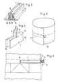
- FIG. 7 shows that broken-off part of the material web 4 (the material is the cardboard coated on both sides with plastic), in which the dividing cut line 5 is shown within the tube between two successive packs. Therefore, you can also see another cross weld 3 consent, which belongs to the bottom side of the next pack, at about the same distance from the dividing line 5.
- the opening device is generally designated 6, which only after the opening process according to Figure 2 is still partially present and consists of a double-sided, one-sided sealing opening strip 7, which is shown in broken lines in FIGS. 1 and 5, but is also at least partially shown in FIGS. 3, 4 and 6 to 8. This opening strip 7 is therefore explained in detail.
- the opening strip 7 is connected on its outer sides along the sealing seams 3a and 3b to the inner sides of the double cardboard strip 2.
- the opening strip 7 (seen in the direction of tearing) is welded to itself at the beginning and end, i.e. flat on its inner sides, whereby an initial sealing region l2 and an end sealing region l3 are formed.
- the opening strip 7 is at the same time fastened in the longitudinal weld seam l, in particular at the point l6 (FIG. 7) where the longitudinal weld seam l and the transverse weld seam 3 intersect.
- the tear-open slot l7 which extends from the front outside from the point l8 (FIG. 8) upwards to the end l9 in the vicinity of the upper connecting web 9. It completely penetrates the opening strip 7, as can best be seen in FIG.
- FIG. 7 A first embodiment can be seen in FIG. 7, in which the width of the double cardboard strip 2 is designated by "a", the upper edge of which is defined by the dash-dotted cut line 5. Less than this width "a” is the width or height "b" of the opening strip 7, which is shown in FIG. 7 with simple dashed lines in the first embodiment.
- a second embodiment is shown with double dashed lines, in which this opening strip 7 has the width "c", which can be twice the width "b”. In this case it is the opening strip 7, which is provided protruding from the double cardboard strip 2 into the interior of the package.
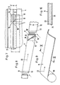
- the plastic web 8 of the opening strip 7 is pulled off a supply roll 20 shown in FIG. 9 and folded in a U-shape, as indicated at the right end of FIG. 9 in the initial state.
- FIG. 1 a first layer 2l made of polyester stretched in the longitudinal direction 22, on the surface of which a second plastic layer 23 made of a thermoplastic ionomer resin based on crosslinked ethylene copolymers and on the side opposite (namely the lower) side of this in FIG a third layer 24 of PETG is laminated on.
- the first layer 2l loses its sievability by stretching. This is not the case with the second and third plastic layers 23, 24, which is why the second 23 and third plastic layers 24 are more sealable than the first plastic layer.
- the two outer layers 23 and 24 also differ from one another in that the second plastic layer 23 coming on the outside of the opening strip 7 according to FIG. 8 has a lower sealability temperature than the third plastic layer 24 has.
- the pouring tip 25 can be seen in FIGS. 2 and 11, with FIG. 11 being highly schematic in order to clarify the individual layers and, for example, no sealing seams or parts pressed onto one another can be seen.
- This makes it possible to display the opening strip 7 with the gripping tab l4 and the end sealing area l3, which would otherwise become invisible if the lines were narrow.
- the peculiarity of FIG. 11 is that the end sealing area l3 does not lie at the front of the pouring tip 25 but only in the vicinity thereof, i.e. is arranged in the pouring area generally designated A.
- the opening strip 7 is longer than, for example, in the embodiment in FIG. According to FIG. 11, the strip 7 with the end sealing region l3 is pulled out over the pouring tip 25 to the top right and is only attached there.
- a paper 4 prepared with an opening strip 7 cannot be wound onto a supply roll because it would become too thick on one side. It is therefore preferred if the method described above begins in the area of a packaging machine or filling machine.
- an aluminum foil can be welded onto one side of the paper web between the paper and the plastic coating, ie the polyethylene.
- the sealing can take place according to the invention, preferably here by means of high frequency. The heat then arises in the aluminum foil and only softens the plastic in the vicinity of the irradiated area. Even in such a case, it is avoided that the opening strip 7 is sealed, for example, on its inner sides, as was deliberately carried out beforehand in the initial sealing region l2 and in the final sealing region l3 at a higher sealing temperature.
- the opening strip is produced in such a way that the three plastic layers are first laminated onto one another, and this layer structure is stretched as a whole, etc.
Landscapes
- Engineering & Computer Science (AREA)
- Mechanical Engineering (AREA)
- Cartons (AREA)
- Physical Or Chemical Processes And Apparatus (AREA)
- Making Paper Articles (AREA)
- Thermally Insulated Containers For Foods (AREA)
- Processing And Handling Of Plastics And Other Materials For Molding In General (AREA)
- Containers And Plastic Fillers For Packaging (AREA)
Abstract
Description
- Die Erfindung betrifft eine Packung für Flüssigkeiten aus mit Kunststoff beschichtetem Kartonträgermaterial, mit einer Längsschweißnaht und mindestens einer in einem doppelten Kartonstreifen an der Oberseite der Packung liegenden Querschweißnaht, in welcher eine Öffnungsvorrichtung in Form eines doppelt gelegten, einseitig dichten Öffnungsstreifens angeordnet ist, dessen Außenseiten mit den Innenseiten des doppelten Kartonstreifens verbunden sind und der aus einem laminierten Kunststoff besteht, dessen eine Schicht in einer Richtung ausgerichtet ist.
- Es sind zahlreiche Flüssigkeitspackungen aus mit Kunststoff beschichtetem Papier, Karton oder dergleichen bekannt, beispielsweise in parallelepipedischer Form. Bei derartigen Flüssigkeitspackungen gibt es Längsschweißnähte, die sich über die Höhe der stehenden parallelepipedischen Packung erstrecken, und Querschweißnähte im Boden und/oder Oberwandbereich der Packung. Die übliche parallelepipedische Flüssigkeitspackung hat mindestens im oberen Bereich an gegenüberliegenden Seiten zwei Dreiecklappen, und der eingangs erwähnte doppelte Kartonstreifen erstreckt sich bei dieser bekannten Packung von der Spitze des einen Dreiecklappens bis zur Spitze des gegenüberliegenden anderen Dreiecklappens.
- Zahlreiche Vorschläge für Öffnungseinrichtungen an derartigen Flüssigkeitspackungen sind teilweise überlegt und teilweise auch bereits in der Literatur beschrieben worden. Eine bekannte Öffnungsvorrichtung besteht aus einem Stück Schlauch aus laminiertem Kunststoff, wobei die Schlauchachse parallel zur Längsschweißnaht und folglich quer zur Querschweißnaht verläuft. Zur Verbesserung der Reißeigenschaften eines solchen laminierten Kunststoffschlauches ist die eine Schicht in Reißrichtung ausgerichtet bzw. orientiert, und auf dieser Schicht ist außen, wo die Verbindung mit dem doppelten Kartonstreifen geschaffen werden muß, eine besser siegelfähige Kunststoffschicht auflaminiert. Damit der als Öffnungsvorrichtung dienende Schlauchteil aus Kunststoff verschlossen werden kann, muß entweder der Schlauch aus dem doppelten Kartonstreifen der Flüssigkeitspackung nach oben herausstehen, wodurch sich der Nachteil ergibt, daß eine solche Flüssigkeitspackung nicht vom Schlauch hergestellt werden kann. Oder der Schlauch muß auf seiner dem inneren der Packung zugewandten Seite verschweißbar sein, weshalb die Bereiche geringerer Siegelfähigkeit besonders angeordnet, vorzugsweise zum Packungsinneren nach unten hin herausstehen müssen. Hierdurch ergibt sich der Nachteil, daß einerseits von außen zugängliche Taschen innerhalb des Schlauchstückes mit den damit verbundenen Hygieneproblemen gebildet werden und andererseits eine komplizierte Herstellung des Schlauchstückes den Einbau einer solchen Öffnungsvorrichtung unwirtschaftlich macht.
- Der Erfindung liegt daher die Aufgabe zugrunde, eine Packung für Flüssigkeiten der eingangs näher bezeichneten Art zu schaffen, bei deren Herstellung aus einem Schlauch eine für den Endverbraucher verständliche Aufreißtätigkeit bei einfacher und preiswert herstellbarer Öffnungsvorrichtung mit guten Hygieneeigenschaften ermöglicht wird.
- Diese Aufgabe wird erfindungsgemäß dadurch gelöst, daß der Öffnungsstreifen im Querschnitt U-förmig ausgebildet und derart angeordnet ist, daß die freien Enden der Schenkel des U auf das Innere der Packung zu gerichtet sind, die Schenkel des U nur am Anfang und Ende des Öffnungsstreifens zu einem Anfangs- und einem Endsiegelbereich zusammengeschweißt sind, der Anfangssiegelbereich zu einem ersten Teil eine aus dem doppelten Kartonstreifen herausstehende Greiflasche vorsieht und zum anderen zweiten Teil im Bereich der sich kreuzenden Längs- und Querschweißnaht in dem doppelten Kartonstreifen versiegelt ist und daß der Endsiegelbereich im Ausgießbereich der Öffnungsvorrichtung in dem doppelten Kartonstreifen versiegelt ist. Durch die neuartige Ausgestaltung und Anordnung des Öffnungsstreifens gemäß der Erfindung ist die Bildung von außen zugänglichen Taschen, in denen sich Verunreinigungen sammeln können, mit Vorteil ausgeschaltet. Der Endverbraucher erkennt sofort die aus dem doppelten Kartonstreifen herausstehende Greiflasche, die er zweifellos erfaßt und in der einzig möglichen Richtung, nämlich zur Ausgießseite der Öffnungsvorrichtung hin hochreißt. Dabei stellt der Verbraucher mit Überraschung fest, daß nicht etwa der Öffnungsstreifen vom doppelten Kartonstreifen abgerissen wird sondern daß sich der Öffnungsstreifen selbst oben, wo der Verbindungssteg die beiden Schenkel des U verbindet, öffnet. Dadurch sind eine verständliche Aufreißtätigkeit für den Endverbraucher und gute Hygieneeigenschaften gegeben. Außerdem ist die Anbringung des neuen Öffnungsstreifens, einschließlich Ausgestaltung und Herstellung wirtschaftlich sehr sparsam für den Packungshersteller.
- Der Anfangssiegelbereich erhält seinen Namen daher, weil der Endverbraucher hier den Reißvorgang anfängt. Nur ein Teil dieses Bereiches bildet die Greiflasche, der andere zweite Teil bildet den vorderen Verschluß, während der Endsiegelbereich den hinteren Verschluß des Öffnungsstreifens mit dem doppelten Kartonstreifen bildet. Oben, d.h. nach außen hin, ist der Öffnungsstreifen - über seinen Verbindungssteg - geschlossen.
- Der Endsiegelbereich muß nicht genau an der Spitze des Gießendes, also in der Spitze des doppelt gelegten Dreiecklappens, einer parallelepipedischen Packung angeordnet sein, vielmehr kann sich erwünschtenfalls der Öffnungsstreifen mit Endsiegelbereich über die Stelle der Ausgießspitze hinaus umgefaltet verlängern, so daß er auch dann noch im Ausgießbereich verbleibt. Mit anderen Worten kann der Öffnungsstreifen dadurch kürzer oder länger ausgebildet sein, und man kann das Anheften und Fixieren des Öffnungsstreifens an der Materialbahn beeinflussen, beispielsweise durch größere Flächen verstärken.
- Zweckmäßig ist die Erfindung dadurch weiter ausgestaltet, daß von den unteren freien Schenkelenden außen vorn an der Greiflasche, sich nach oben hinten erstreckend, ein Aufreißschlitz, den Öffnungsstreifen vollständig durchsetzend, innerhalb des Anfangssiegelbereiches angebracht ist. Dieser Aufreißschlitz erleichtert den Öffnungsvorgang, weil die Anfangsreißstelle durch diesen Schlitz gesteuert an die richtige Position im Öffnungsstreifen gelegt wird bzw. das Aufreißen an der richtigen Stelle in der Nähe des oberen Verbindungssteges beginnt.
- Deshalb ist es besonders vorteilhaft, wenn das Ende des Aufreißschlitzes nahe dem oberen Verbindungssteg der beiden Schenkel des Öffnungsstreifens vorgesehen ist. Beim unbedachten Hochreißen des Verbindungssteges durch den Endverbraucher beginnt das Einreißen im oberen Bereich des Öffnungsstreifens und damit auch des doppelten Kartonstrei fens, und es wird ein seitliches Beginnen des Reißens und gegebenenfalls Zerstören des doppelten Kartonstreifens hierdurch besonders gut vermieden. Der Öffnungsstreifen wird praktisch nur längs seines eigenen oberen Verbindungssteges geöffnet.
- Wenn gemäß der Erfindung der Verbindungssteg des Öffnungsstreifens innerhalb der Außenkontur des doppelten Kartonstreifens angeordnet ist, kann man die Flüssigkeitspackung besonders gut aus einem Schlauch herstellen, weil die gefüllte Bahn in der Füllmaschine dann stets außerhalb des Öffnungsstreifens, und zwar unmittelbar außerhalb desselben, durchgeschnitten wird. Die Trennschnittlinie zwischen zwei innerhalb des Schlauches aufeinanderfolgenden Packungen liegt also unmittelbar außerhalb des Öffnungsstreifens, so daß dieser geschlossen bleibt und dennoch die Packung vereinzelt werden kann.
- Wenn aus bevorzugten Gründen ein breiterer Öffnungsstreifen verwendet werden soll, kann es erfindungsgemäß auch günstig sein, wenn der Öffnungsstreifen aus dem doppelten Kartonstreifen heraus in das Innere der Packung hineinragend vorgesehen ist.
- Bei der Herstellung von Flüssigkeitspackungen aus einem Schlauch erfolgt in an sich bekannter Weise beidseitig neben der Schnittlinie das Abdichten des jeweiligen Endes der beiden voneinander zu trennenden Packungen, und die Anordnung des Öffnungsstreifens und sein Ansiegeln an der Materialbahn muß auf die Lage der jeweiligen Quersiegelnaht so abgestellt sein, daß keinerlei Undichtigkeiten zu befürchten sind. In diesem Sinne ist es erfindungsgemäß besonders zweckmäßig, wenn sich der Anfangssiegelbereich über die ganze Breite des Öffnungsstreifens erstreckt. Der Schweißbereich des Öffnungsstreifens erstreckt sich also über die Längssiegelnaht-in das Packungsinnere hinein-hinaus, wodurch die Sicherheit gegeben ist, daß aus dem Inneren der Packung keine Flüssigkeit nach außen dringen kann, auch nicht, wenn der Aufreißschlitz vorgesehen ist.
- Zweckmäßig ist es gemäß der Erfindung ferner, wenn vorzugsweise vom Ende des Aufreißschlitzes ausgehend, zwei im Abstand eines Reißstreifens voneinander befindliche Schwächungslinien im Bereich des Verbindungssteges des Öffnungsstreifens längs desselben verlaufend vorgesehen sind. Diese Maßnahme gibt eine Vorzugsreißrichtung vor, wodurch das Aufreißen ohne Zutun des Endverbrauchers in die richtigen Bahnen gesteuert wird. Bei diesen Schwächungslinien kann es sich um verdünnte Bereiche oder dergleichen handeln, eine echte Perforation ist natürlich nicht möglich, denn die Schwächungslinien müssen flüssigkeitsdicht bleiben.
- Der Endsiegelbereich kann auch in enger Nachbarschaft der Ausgießspitze der Öffnungsvorrichtung angeschweißt sein, und der Öffnungsstreifen kann sich von der Greiflasche neben der Längssiegelnaht bis an die Ausgießspitze erstrecken. Es hat sich nämlich gezeigt, daß zur Einsparung von Material es im allgemeinen ausreicht, wenn der Öffnungsstreifen gerade so lang ausgebildet wird wie die Öffnung für das Ausgießen ist. Alternative Möglichkeiten zum Herumlegen des Öffnungsstreifens um die Ausgießspitze wurden oben erläutert.
- Zweckmäßig ist es erfindungsgemäß auch, wenn auf der Oberfläche der in Längsrichtung des Öffnungsstreifens ausgerichteten ersten Kunststoffschicht eine zweite, besser wärmesiegelfähige Kunststoffschicht als die erste Schicht und auf der anderen, gegenüberliegenden Oberfläche der ersten Schicht eine dritte, ebenfalls besser wärmesiegelfähige Kunststoffschicht als die erste Schicht aufgebracht sind und wenn die Siegelfähigkeitstemperatur der zweiten Schicht niedriger als die der dritten Schicht ist. Ein solcher Kunststoffaufbau begünstigt das Ansiegeln des Öffnungsstreifens an die jeweilige innere Oberfläche des doppelten Kartonstreifens, ohne daß dadurch die Schenkel des Öffnungsstreifens innen auf sich selbst oder miteinander versiegelt würden. Anders ausgedrückt wäre die Packung durch Hochreißen des oberen Verbindungssteges - wie vorgesehen - nicht zu öffnen, wenn der Öffnungsstreifen weiter unten vollständig verschlossen wäre. Die Materialkombination der einzelnen Kunststoffschichten schaltet derartige Probleme vollständig aus.
- Die Packung mit den vorstehend erwähnten Merkmalen ist gemäß einer weiteren Überlegung erfindungsgemäß auch dadurch zu kennzeichnen, daß die erste Schicht aus in Längsrichtung des Öffnungsstreifens gerecktem Polyester, die zweite Schicht aus einem thermoplastischen Ionomerharz auf der Basis von vernetzten Ethylencopolymeren und die dritte Schicht aus PETG besteht. Bei letzteren kann man beispielsweise cyclohexanmodifiziertes Polyester verwenden. Es hat sich nämlich gezeigt, daß auch beim Strecken eines solchen Materiales dieses nicht kristallin wird und somit seine Wärmesiegelfähigkeit behält. Dadurch ist der Öffnungsstreifen gemäß der Erfindung besonders gut und einfach herstellbar und mit der Verpackung in zweckmäßiger Weise zu verbinden.
- Die vorstehend erwähnte Aufgabe wird im Hinblick auf eine Herstellung einer Flüssigkeitspackung der eingangs genannten Art dadurch gelöst, daß erfindungsgemäß die Kunststoffbahn des Öffnungsstreifens von einer Vorratsrolle abgezogen, gegebenenfalls doppelt gefaltet wird, der U-förmig gefaltete Öffnungsstreifen am Anfang und Ende unter Bildung von Anfangs- und Endsiegelbereichen auf seinen Innenseiten auf sich selbst verschweißt wird, auf seiner einen Außenseite registergerecht auf die die Innenseite der Packung bildende Seite der flachliegenden Materialbahn derart aufgesiegelt wird, daß der die Greiflasche bildende zweite Teil des Anfangssiegelbereiches über die Schnittkante der Längssiegelnaht und senkrecht zu dieser herausragt, daß ferner die Materialbahn zu einem Tubus geformt, mit der Längsschweißnaht versehen, gefüllt und durch Querschweißen längs durch den Öffnungsstreifen verschlossen, vereinzelt und in die Endgestalt einer Packung geformt wird. Eine leistungsstarke und übersichtliche Herstellung ist durch diese Maßnahmen gegeben, weil eine kontinuierliche Produktion auch mit großer Stückzahl pro Zeiteinheit ermöglicht ist. Das Falten des Kunststoffilmes des Öffnungsstreifens in U-Form auf sich selbst und Verschweißen auf sich selbst erfolgt mit höherer Temperatur, denn vorzugsweise wird hier die oben erwähnte dritte Kunststoffschicht mit sich selbst verschweißt, wozu höhere Temperaturen als beim Erstellen der üblichen Längs- oder Querschweißnähte der Papierbahn erforderlich sind. Durch dieses Verschweißen des doppelt gefalteten Öffnungsstreifens auf sich selbst - und zwar nur in den Anfangs- und den Endsiegelbereichen - erreicht man eine Verfestigung und Versteifung dieser verschweißten Bereiche. Das kommt besonders der Greiflasche zugute, die besonders dann zweckmäßig zu handhaben ist, wenn sie fest und steif ausgebildet ist. Diese Eigenschaften ergeben sich aber von allein gerade durch dieses Herstellungsverfahren.
- Das registergerechte Anheften des somit vorbereiteten Öffnungsstreifens auf die Innenseite der Packungsbahn ist technisch nicht schwierig, auch nicht mit der Bedingung, daß die Greiflasche über die Schnittkante der Bahn quer zu dieser hinaussteht. Die Längsrichtung des Öffnungsstreifens liegt also quer zur Schnittkante oder zur späteren Längssiegelnaht. Wenn nämlich die mit dem Öffnungsstreifen somit versehene Materialbahn dann zum Tubus geformt und über die Längsschweißnaht verschlossen wird, steht die Greiflasche aus dieser Längsschweißnaht heraus. Die danach üblichen Schritte zur Erstellung der Packung sind an sich bekannt.
- Es ist bei der Herstellung einer solchen Flüssigkeitspakkung besonders günstig, wenn erfindungsgemäß ferner vor oder nach dem Doppelfalten des Öffnungsstreifens sowie dem teilweisen Verschweißen desselben auf sich selbst ein Aufreißschlitz in den Anfangssiegelbereich eingebracht wird. Über Lage and Anordnung dieses Aufreißschlitzes ist oben bereits geschrieben. Deshalb ist es erfindungsgemäß beson ders zweckmäßig, wenn von den unteren freien Schenkelenden außen vorn an der Greiflasche sich nach oben hinten erstreckend der Aufreißschlitz, den Öffnungsstreifen vollständig durchsetzend, innerhalb des Anfangssiegelbereiches angebracht wird. Dabei sei wiederholt, daß der Aufreißschlitz sowohl vor dem Doppelfalten des Öffnungsstreifens als auch nach seinem Falten, dabei aber vor dem Verschweißen auf sich selbst oder auch danach eingebracht werden kann.
- Die Kunststoffbahn für den Öffnungsstreifen, deren erste Schicht in einer Richtung ausgerichtet ist und auf deren einer Oberfläche eine zweite, besser wärmesiegelfähige Kunststoffschicht als die erste Schicht aufgebracht ist, ist erfindungsgemäß besonders dadurch gekennzeichnet, daß auf der anderen, gegenüberliegenden Oberfläche der ersten Schicht eine dritte, ebenfalls besser wärmesiegelfähige Kunststoffschicht als die erste Schicht aufgebracht ist und daß die Siegelfähigkeitstemperatur der zweiten Schicht niedriger als die der dritten Schicht ist. Unter "Siegelfähigkeitstemperatur" wird hier diejenige Temperatur verstanden, bei welcher das Material siegelfähig ist bzw. wird. Es kann sich hier beispielsweise um die Schmelztemperatur bzw. um die Erweichungstemperatur handeln. Wichtig ist im Sinne der Erfindung, daß das Material bei dieser Temperatur gesiegelt werden kann.
- Es wurde oben bereits angeschnitten, daß die sogenannte zweite Schicht mit der niedrigeren Siegelfähigkeitstemperatur als die dritte Schicht auf der Außenseite des doppelt gefalteten, fertigen Öffnungsstreifen zu liegen kommen muß. Der Sinn der Anordnung der zweiten Schicht außen am Öffnungsstreifen liegt darin, daß beim Zuschweißen der einzelnen Packungen und Vereinzeln voneinander dafür gesorgt wird, daß zwar der Öffnungsstreifen aus Kunststoff flüssigkeitsdicht am doppelten Kartonstreifen haftet, daß aber der Öffnungsstreifen selbst über den größten Bereich seiner Fläche nach unten zum Packungsinneren hin offen ist und nur durch seinen oberen Verbindungssteg geschlossen bleibt. Sinn dieser Maßnahme ist es, daß die Packung nur dann geöffnet werden kann, weil die Öffnung nur durch Abreißen des oberen Verbindungssteges erfolgt.
- Besonders günstig hat es sich erfindungsgemäß gezeigt, wenn die erste Schicht aus in Längsrichtung des Öffnungsstreifens gerecktem Polyester, die zweite Schicht der Kunststoffbahn aus einem thermoplastischen Ionomerharz auf der Basis von vernetzten Ethylencopolymeren und die dritte Schicht aus PETG besteht. PETG wurde bereits erwähnt. Das erwähnte thermoplastische Ionomerharz wird mit dem Warenzeichen "SURLYN" der Firma Du Pont vertrieben. Beispielsweise handelt es sich dabei um einen durchsichtigen, gegen Öle und Fette widerstandsfähigen Kunststoff für die Verpackungsindustrie, der gut schweißfähig ist.
- Weitere Vorteile, Merkmale und Anwendungsmöglichkeiten der vorliegenden Erfindung ergeben sich aus der folgenden Beschreibung bevorzugter Ausführungsbeispiele anhand der folgenden Zeichnungen. Es zeigen:
- Figur l perspektivisch eine mit der erfindungsgemäßen Öffnungsvorrichtung versehene Flüssigkeitspackung, bei welcher die oberen, äußeren Dreiecklappen hochgestellt sind,
- Figur 2 abgebrochen perspektivisch den linken Teil der geöffneten Packung, leicht von oben gesehen, wobei die Greiflasche und der obere Verbindungssteg abgerissen sind,
- Figur 3 eine perspektivische, schematische und abgebrochene Schnittansicht längs der Linie III-III der Figur l,
- Figur 4 eine schematische perspektivische Ansicht des U-förmig gelegten Öffnungsstreifens, dessen oberer Verbindungssteg zur Hälfte hochgerissen ist, unter Darstellung von Schwächungslinien,
- Figur 5 abgebrochen den Zustand der Materialbahn, wenn diese zum Tubus gelegt wird, damit die Längssiegelnaht erstellt werden kann,
- Figur 6 ein abgebrochen gezeigtes Teilstück einer flachgelegten Materialbahn, bei welcher der U-förmig gefaltete Öffnungsstreifen plaziert und fixiert ist,
- Figur 7 das rechte Ende des Öffnungsstreifens auf einem abgebrochenen Teil der Materialbahn in größerem Maßstab als in Figur 6,
- Figur 8 perspektivisch und abgebrochen ein vereinzelter Öffnungsstreifen zwischen abgebrochenen Teilen der doppelt gelegten Kunststoffbahn,
- Figur 9 die Kunststoffbahn, wie sie von der Vorratsrolle abgezogen und teilweise schon U-förmig gefaltet wird,
- Figur l0 eine Schnittansicht der Kunststoffbahn entlang der Linie X-X in Figur 9 und
- Figur ll die Draufsicht auf den doppelten Kartonstreifen mit eingelegtem Öffnungsstreifen bei einer anderen Ausführungsform der Erfindung, bei welcher nämlich der Endsiegelbereich über die Ausgießspitze hinausgezogen und erst weiter hinten aufgesiegelt ist.
- In den Figuren l und 2 sieht man schematisch die geschlossene bzw. geöffnete Flüssigkeitspackung aus mit Kunststoff beschichtetem Kartonträgermaterial, mit der Längsschweißnaht l und dem doppelten Kartonstreifen 2 mit den Einzelwandungen 2ʹ und 2ʺ, in welchem die Querschweißnaht 3 (Figur 7) angeordnet ist. In Figur 7 ist derjenige abgebrochene Teil der Materialbahn 4 gezeigt (das Material ist der beidseitig mit Kunststoff beschichtete Karton), bei welchem die Trennschnittlinie 5 innerhalb des Tubus zwischen zwei aufeinanderfolgenden Packungen gezeigt ist. Deshalb sieht man auch etwa in gleichem Abstand von der Trennlinie 5 eine weitere Querschweißnaht 3ʹ, welche zur Bodenseite der nächsten Packung gehört.
- In Figur l ist allgemein mit 6 die Öffnungsvorrichtung bezeichnet, die nach dem Öffnungsvorgang gemäß Figur 2 nur noch teilweise vorhanden ist und aus einem doppelt gelegten, einseitig dichten Öffnungsstreifen 7 besteht, der in den Figuren l und 5 gestrichelt dargestellt ist, wenigstens teilweise aber auch in den Figuren 3, 4 und 6 bis 8 dargestellt ist. Dieser Öffnungsstreifen 7 wird daher besonders ausführlich erläutert.
- Er ist aus einer Kunststoffbahn 8 (Figuren 9 und l0) erstellt und U-förmig gefaltet, wie man deutlich aus den Figuren 3, 4 und 8 erkennt. Das U ist nach unten offen, d.h. zum Inneren der Verpackung hin. Der obere Verbindungssteg 9 ist der flüssigkeitsdichte Abschluß, welcher die beiden Schenkel l0, l0ʹ miteinander verbindet. Bei der Ausführungsform der Figur 4 wird er durch Schwächungslinien ll von den Schenkeln l0, l0ʹ getrennt.
- Um die Packung flüssigkeitsdicht zu machen, ist der Öffnungsstreifen 7 auf seinen Außenseiten längs der Siegelnähte 3a und 3b mit den Innenseiten des doppelten Kartonstreifens 2 verbunden. Außerdem ist der Öffnungsstreifen 7 (in Reißrichtung gesehen) am Anfang und Ende auf sich selbst verschweißt, d.h. flächig auf seinen Innenseiten, wodurch ein Anfangssiegelbereich l2 und ein Endsiegelbereich l3 gebildet werden.
- Innerhalb des Anfangssiegelbereiches l2 gibt es einen ersten Teil l4, welcher die Greiflasche bildet, die in mehreren Zeichnungen deutlich herausstehend dargestellt ist. Über den zweiten Teil l5 ist der Öffnungsstreifen 7 zugleich in der Längsschweißnaht l befestigt, insbesondere an der Stelle l6 (Figur 7), wo sich die Längsschweißnaht l und die Querschweißnaht 3 kreuzen. Innerhalb des Anfangssiegelbereiches l2 erkennt man auch den Aufreißschlitz l7, der sich von außen vorn von der Stelle l8 (Figur 8) nach oben hinten bis zum Ende l9 in der Nähe des oberen Verbindungssteges 9 erstreckt. Er durchsetzt dabei den Öffnungsstreifen 7 vollständig, wie sich am besten aus Figur 8 ergibt.
- Aus Figur 7 erkennt man eine erste Ausführungsform, bei welcher mit "a" die Breite des doppelten Kartonstreifens 2 bezeichnet ist, dessen Oberkante durch die strichpunktierte Schnittlinie 5 definiert wird. Kleiner als diese Breite "a" ist die Breite oder Höhe "b" des Öffnungsstreifens 7, der in Figur 7 mit einfachen gestrichelten Linien bei der ersten Ausführungsform dargestellt ist. In der gleichen Figur 7 ist mit doppeltliegenden gestrichelten Linien eine zweite Ausführungsform gezeigt, bei welcher eben dieser Öffnungsstreifen 7 die Breite "c" hat, die das Doppelte der Breite "b" betragen kann. In diesem Falle handelt es sich um den Öffnungsstreifen 7, welcher aus dem doppelten Kartonstreifen 2 heraus in das Innere der Packung hineinragend vorgesehen ist.
- Bei der Herstellung wird die Kunststoffbahn 8 des Öffnungsstreifens 7 von einer in Figur 9 gezeigten Vorratsrolle 20 abgezogen und U-förmig gefaltet, wie am rechten Ende der Figur 9 bereits im Anfangszustand angedeutet ist.
- Legt man eine Schnittlinie gemäß der Linie X-X durch Figur 9, dann sieht man den Aufbau der Kunststoffbahn 8, wie in Figur l0 gezeigt ist. Man hat hier eine erste Schicht 2l aus in Längsrichtung 22 gerecktem Polyester, auf dessen einer Oberfläche eine zweite Kunststoffschicht 23 aus einem thermoplastischen Ionomer-Harz auf der Basis von vernetzten Ethylencopolymeren und auf der dieser in Figur l0 oben liegenden Seite gegenüberliegenden (nämlich unteren) Seite eine dritte Schicht 24 aus PETG auflaminiert ist. Die erste Schicht 2l verliert ihre Siegefähigkeit durch das Recken. Dies ist bei der zweiten und dritten Kunststoffschicht 23, 24 nicht der Fall, weshalb die zweite 23 und dritte Kunststoffschicht 24 besser siegelfähiger als die erste Kunststoffschicht sind. Die beiden äußeren Schichten 23 und 24 unterscheiden sich außerdem dadurch voneinander, daß die auf dem Öffnungsstreifen 7 gemäß Figur 8 außen zu liegen kommende zweite Kunststoffschicht 23 eine niedrigere Siegelfähigkeitstemperatur als die dritte Kunststoffschicht 24 hat.
- In den Figuren 2 und ll erkennt man die Ausgießspitze 25, wobei Figur ll zur Verdeutlichung der einzelnen Schichten stark schematisiert ist und beispielsweise keinerlei Siegelnähte oder aufeinandergedrückte Teile zu sehen sind. Hierdurch ist es möglich, den Öffnungsstreifen 7 mit der Greiflasche l4 und dem Endsiegelbereich l3 darzustellen, die anderenfalls bei der Enge der Linien unsichtbar würden. Die Besonderheit der Figur ll besteht darin, daß der Endsiegelbereich l3 nicht vorn an der Ausgießspitze 25 sondern lediglich in dessen Nähe, d.h. im allgemein mit A bezeichneten Ausgießbereich angeordnet ist. Bei der Ausführungsform der Figur ll ist der Öffnungsstreifen 7 länger als beispielsweise bei der Ausführungsform der Figur l. Gemäß Figur ll ist nämlich der Streifen 7 mit dem Endsiegelbereich l3 über die Ausgießspitze 25 nach rechts oben hinausgezogen und erst dort befestigt.
- Im allgemeinen ist ein mit einem Öffnungsstreifen 7 präpariertes Papier 4 nicht auf eine Vorratsrolle aufzuwickeln, weil es einseitig zu dick würde. Deshalb ist es bevorzugt, wenn das oben beschriebene Verfahren im Bereich einer Pakkungsherstellungsmaschine oder Füllmaschine beginnt.
- Bei der Verpackung von speziellen Flüssigkeiten, wie z.B. H-Milch oder Fruchtsaft, kann auf einer Seite der Papierbahn zwischen dem Papier und der Kunststoffbeschichtung, d.h. dem Polyethylen, eine Aluminiumfolie aufgeschweißt sein. Auch in diesem Falle kann das Versiegeln erfindungsgemäß erfolgen, vorzugsweise hier mittels Hochfrequenz. Die Wärme entsteht dann in der Aluminiumfolie und erweicht nur den in der Nachbarschaft der bestrahlten Stelle befindlichen Kunststoff. Auch in einem solchen Falle ist vermieden, daß sich der Öffnungsstreifen 7 etwa auf seinen Innenseiten versiegelt wird, wie dies bewußt zuvor im Anfangssiegelbereich l2 und im Endsiegelbereich l3 bei höherer Siegeltemperatur durchgeführt wurde.
- Der Öffnungsstreifen wird so hergestellt, daß zuerst die drei Kunststoffschichten aufeinanderlaminiert werden, und dieser Schichtaufbau insgesamt gereckt wird usw.
Claims (15)
Priority Applications (1)
| Application Number | Priority Date | Filing Date | Title |
|---|---|---|---|
| AT87105546T ATE77798T1 (de) | 1986-04-28 | 1987-04-14 | Fluessigkeitspackung, herstellung derselben und kunststoffbahn zur herstellung der fluessigkeitspackung. |
Applications Claiming Priority (2)
| Application Number | Priority Date | Filing Date | Title |
|---|---|---|---|
| GB8610324A GB2189772B (en) | 1986-04-28 | 1986-04-28 | A liquid pack and method of manufacture thereof |
| GB8610324 | 1986-04-28 |
Publications (3)
| Publication Number | Publication Date |
|---|---|
| EP0244674A2 true EP0244674A2 (de) | 1987-11-11 |
| EP0244674A3 EP0244674A3 (en) | 1989-03-15 |
| EP0244674B1 EP0244674B1 (de) | 1992-07-01 |
Family
ID=10596962
Family Applications (1)
| Application Number | Title | Priority Date | Filing Date |
|---|---|---|---|
| EP87105546A Expired - Lifetime EP0244674B1 (de) | 1986-04-28 | 1987-04-14 | Flüssigkeitspackung, Herstellung derselben und Kunststoffbahn zur Herstellung der Flüssigkeitspackung |
Country Status (9)
| Country | Link |
|---|---|
| US (1) | US4787507A (de) |
| EP (1) | EP0244674B1 (de) |
| JP (1) | JP2523318B2 (de) |
| AT (1) | ATE77798T1 (de) |
| AU (1) | AU598535B2 (de) |
| CA (1) | CA1276922C (de) |
| DE (1) | DE3780074D1 (de) |
| ES (1) | ES2033254T3 (de) |
| GB (1) | GB2189772B (de) |
Cited By (2)
| Publication number | Priority date | Publication date | Assignee | Title |
|---|---|---|---|---|
| CN112429361A (zh) * | 2020-11-18 | 2021-03-02 | 乐美包装(昆山)有限公司 | 包装容器及其坯料 |
| EP3237293B1 (de) * | 2014-12-22 | 2024-01-17 | Tetra Laval Holdings & Finance SA | Verpackungsmaterial sowie daraus hergestellter verpackungsbehälter |
Families Citing this family (14)
| Publication number | Priority date | Publication date | Assignee | Title |
|---|---|---|---|---|
| SE459916B (sv) * | 1987-12-23 | 1989-08-21 | Roby Teknik Ab | Oeppningsanordning vid foerpackningsbehaallare |
| JP2792903B2 (ja) * | 1989-04-11 | 1998-09-03 | 大日本印刷株式会社 | 容 器 |
| CH679850A5 (de) * | 1989-09-05 | 1992-04-30 | Tetra Pak Romont | |
| JPH03176348A (ja) * | 1989-11-24 | 1991-07-31 | Tsunetoshi Kobayashi | 開封用具付紙パック類の製造方法 |
| US5083702A (en) * | 1990-03-22 | 1992-01-28 | Minnesota Mining And Manufacturing Company | Gable-top container and method and apparatus for construction thereof |
| US5228616A (en) * | 1990-08-14 | 1993-07-20 | Tetra Alfa Holdings S.A. | Package container provided with a strip-type opening arrangement |
| US5080233A (en) * | 1990-11-21 | 1992-01-14 | Minnesota Mining And Manufacturing Company | Gable top container having reduced opening force and method for construction therefor |
| SE469939B (sv) * | 1992-03-03 | 1993-10-11 | Tetra Laval Holdings & Finance | Materialbana för tillverkning av förpackningsbehållare med öppningsanordning innefattande en dragremsa |
| SE508001C2 (sv) * | 1992-07-02 | 1998-08-10 | Tetra Laval Holdings & Finance | Öppningsanordning för förpackningsbehållare |
| EP0708000A3 (de) * | 1994-10-21 | 1996-08-14 | Hoover Universal | Sitzbezug |
| EP1275588A1 (de) * | 2001-07-12 | 2003-01-15 | Tetra Laval Holdings & Finance SA | Giebelbehälter für fliessfähige Nahrungsmittel |
| EP1584563A1 (de) * | 2004-04-09 | 2005-10-12 | Tetra Laval Holdings & Finance S.A. | Giebelpackung für fliessfähige Nahrungsmitteln und Konstruktionsmethode dafür |
| DE102007021048A1 (de) * | 2007-05-04 | 2008-11-06 | Poly-Clip System Gmbh & Co. Kg | Aufreißstreifen und Verfahren zu dessen Bereitstellung |
| DE102016003824A1 (de) * | 2016-04-04 | 2017-10-05 | Sig Technology Ag | Packungsmantel, Verpackung und Verfahren zur Herstellung einer Verpackung |
Family Cites Families (16)
| Publication number | Priority date | Publication date | Assignee | Title |
|---|---|---|---|---|
| NL97811C (de) * | 1953-01-16 | |||
| US2961365A (en) * | 1954-10-13 | 1960-11-22 | Du Pont | Lamination of polyethylene terephthalate structures |
| US2877500A (en) * | 1955-06-17 | 1959-03-17 | Grace W R & Co | Process for preparing transparent polyethylene |
| US3054703A (en) * | 1957-05-08 | 1962-09-18 | Du Pont | Laminated structures and process |
| DE1193790B (de) * | 1959-03-25 | 1965-05-26 | Jagenberg Werke Ag | Herstellung von Zuschnitten fuer die Maentel konischer Behaelter |
| US3187982A (en) * | 1960-07-21 | 1965-06-08 | Union Carbide Corp | Method for forming coated uniaxially oriented films and the product formed thereby |
| US3188266A (en) * | 1963-09-03 | 1965-06-08 | Minnesota Mining & Mfg | Interface bonding of polymers and product thereof |
| US3455720A (en) * | 1964-08-21 | 1969-07-15 | Du Pont | Post-formable film |
| US3497131A (en) * | 1968-05-20 | 1970-02-24 | Kartridg Pak Co | Package with easy opening device |
| US3560223A (en) * | 1969-06-16 | 1971-02-02 | Tee Pak Inc | Liver sausage with casing and method of preparing same |
| CH546184A (de) * | 1971-01-11 | 1974-02-28 | Altstaedter Verpack Vertrieb | Verpackung fuer fluessigkeiten aus karton oder papier und verfahren zur herstellung der verpackung. |
| BE795478A (fr) * | 1972-02-16 | 1973-08-16 | Cellophane Sa | Films composites en polyesters et leur procede de fabrication |
| CH641400A5 (de) * | 1979-07-26 | 1984-02-29 | Tetra Pak Dev | Verfahren zur herstellung einer gereckten kunststoff-folie mit biaxialer molekuelorientierung. |
| US4362245A (en) * | 1979-12-10 | 1982-12-07 | American Can Company | Liquid tight pouring carton |
| SE428290B (sv) * | 1981-08-28 | 1983-06-20 | Rigello Pak Ab | Oppningsanordning for forpackningsbehallare med trycksatt fyllgods |
| SE451064B (sv) * | 1981-12-30 | 1987-08-31 | Tetra Pak Int | Anordning vid forpackningsbehallare |
-
1986
- 1986-04-28 GB GB8610324A patent/GB2189772B/en not_active Expired
-
1987
- 1987-04-14 DE DE8787105546T patent/DE3780074D1/de not_active Expired - Lifetime
- 1987-04-14 ES ES198787105546T patent/ES2033254T3/es not_active Expired - Lifetime
- 1987-04-14 EP EP87105546A patent/EP0244674B1/de not_active Expired - Lifetime
- 1987-04-14 AT AT87105546T patent/ATE77798T1/de active
- 1987-04-24 AU AU71934/87A patent/AU598535B2/en not_active Ceased
- 1987-04-27 CA CA000535642A patent/CA1276922C/en not_active Expired - Lifetime
- 1987-04-27 US US07/043,033 patent/US4787507A/en not_active Expired - Lifetime
- 1987-04-28 JP JP62103432A patent/JP2523318B2/ja not_active Expired - Fee Related
Cited By (2)
| Publication number | Priority date | Publication date | Assignee | Title |
|---|---|---|---|---|
| EP3237293B1 (de) * | 2014-12-22 | 2024-01-17 | Tetra Laval Holdings & Finance SA | Verpackungsmaterial sowie daraus hergestellter verpackungsbehälter |
| CN112429361A (zh) * | 2020-11-18 | 2021-03-02 | 乐美包装(昆山)有限公司 | 包装容器及其坯料 |
Also Published As
| Publication number | Publication date |
|---|---|
| ATE77798T1 (de) | 1992-07-15 |
| GB2189772A (en) | 1987-11-04 |
| EP0244674A3 (en) | 1989-03-15 |
| GB2189772B (en) | 1989-12-13 |
| AU598535B2 (en) | 1990-06-28 |
| CA1276922C (en) | 1990-11-27 |
| ES2033254T3 (es) | 1993-03-16 |
| JP2523318B2 (ja) | 1996-08-07 |
| EP0244674B1 (de) | 1992-07-01 |
| GB8610324D0 (en) | 1986-06-04 |
| JPS62260648A (ja) | 1987-11-12 |
| DE3780074D1 (de) | 1992-08-06 |
| AU7193487A (en) | 1987-10-29 |
| US4787507A (en) | 1988-11-29 |
Similar Documents
| Publication | Publication Date | Title |
|---|---|---|
| DE69604416T2 (de) | Dichtes behältnis und verfahren zu seiner befüllung mit einer flüssigkeit | |
| DE4028508C2 (de) | Packung, insbesondere für kompressibles Packgut | |
| EP0347522B1 (de) | Aus Folienschlauch hergestellter Verpackungsbeutel | |
| DE2758092C2 (de) | Öffnungsvorrichtung für eine Verpackung aus flexiblem Material | |
| EP0190577B1 (de) | Flüssigkeitspackung mit Giesskante | |
| EP0244674B1 (de) | Flüssigkeitspackung, Herstellung derselben und Kunststoffbahn zur Herstellung der Flüssigkeitspackung | |
| DE3628478C2 (de) | ||
| DE2729383A1 (de) | Verpackungsbehaelter | |
| EP0515896A1 (de) | Beutel | |
| EP0028299B1 (de) | Flüssigkeitspackung mit Ausgiess- und Lufteintrittsöffnung | |
| DE1486576A1 (de) | Leicht zu oeffnender Beutel | |
| DE3301086C2 (de) | Packung auf flächigem Material, wie z.B. Papier, Karton o.dgl. insbesondere quaderförmige Flüssigkeitspackung aus Papier-Kunststoff- Verbund-Material | |
| EP0144736B1 (de) | Flüssigkeitspackung | |
| CH678846A5 (de) | ||
| DE4010822A1 (de) | Kreuzbodensack | |
| EP0049460B1 (de) | Flüssigkeitspackung mit Ausgiessöffnung | |
| DE2155091A1 (en) | Plastic bag - with strong plastic handle welded into the side seams | |
| DE2734250C2 (de) | Flüssigkeitsverpackung mit Aufreißöffnung | |
| DE3644618A1 (de) | Tragbarer verpackungsbeutel aus kunststoffolie mit einstueckig angeformtem griffteil | |
| DE2158076A1 (de) | Parallelepipedfoermige verpackung | |
| DE3445272A1 (de) | Beutel aus thermoplastischer kunststoffolie | |
| DE2928105C2 (de) | Verpackung für Flüssigkeiten mit Ausgießvorrichtung | |
| DE2801404C2 (de) | Flüssigkeitspackung mit durch Reißstreifen zu öffnender Ausgießtülle | |
| DE10131902A1 (de) | Standfähige Schlauchbeutel, Verfahren für deren Herstellung und Vorrichtung zur Durchführung des Verfahrens | |
| DE2107795A1 (de) | Verpackungsbeutel |
Legal Events
| Date | Code | Title | Description |
|---|---|---|---|
| PUAI | Public reference made under article 153(3) epc to a published international application that has entered the european phase |
Free format text: ORIGINAL CODE: 0009012 |
|
| AK | Designated contracting states |
Kind code of ref document: A2 Designated state(s): AT BE CH DE ES FR GB IT LI NL SE |
|
| PUAL | Search report despatched |
Free format text: ORIGINAL CODE: 0009013 |
|
| AK | Designated contracting states |
Kind code of ref document: A3 Designated state(s): AT BE CH DE ES FR GB IT LI NL SE |
|
| 17P | Request for examination filed |
Effective date: 19890814 |
|
| 17Q | First examination report despatched |
Effective date: 19891108 |
|
| RAP1 | Party data changed (applicant data changed or rights of an application transferred) |
Owner name: AB TETRA PAK |
|
| ITTA | It: last paid annual fee | ||
| GRAA | (expected) grant |
Free format text: ORIGINAL CODE: 0009210 |
|
| ITF | It: translation for a ep patent filed | ||
| AK | Designated contracting states |
Kind code of ref document: B1 Designated state(s): AT BE CH DE ES FR GB IT LI NL SE |
|
| REF | Corresponds to: |
Ref document number: 77798 Country of ref document: AT Date of ref document: 19920715 Kind code of ref document: T |
|
| ET | Fr: translation filed | ||
| GBT | Gb: translation of ep patent filed (gb section 77(6)(a)/1977) | ||
| REF | Corresponds to: |
Ref document number: 3780074 Country of ref document: DE Date of ref document: 19920806 |
|
| REG | Reference to a national code |
Ref country code: ES Ref legal event code: FG2A Ref document number: 2033254 Country of ref document: ES Kind code of ref document: T3 |
|
| PLBE | No opposition filed within time limit |
Free format text: ORIGINAL CODE: 0009261 |
|
| STAA | Information on the status of an ep patent application or granted ep patent |
Free format text: STATUS: NO OPPOSITION FILED WITHIN TIME LIMIT |
|
| 26N | No opposition filed | ||
| EAL | Se: european patent in force in sweden |
Ref document number: 87105546.3 |
|
| PGFP | Annual fee paid to national office [announced via postgrant information from national office to epo] |
Ref country code: SE Payment date: 19980319 Year of fee payment: 12 |
|
| PGFP | Annual fee paid to national office [announced via postgrant information from national office to epo] |
Ref country code: NL Payment date: 19980320 Year of fee payment: 12 Ref country code: AT Payment date: 19980320 Year of fee payment: 12 |
|
| PGFP | Annual fee paid to national office [announced via postgrant information from national office to epo] |
Ref country code: CH Payment date: 19980327 Year of fee payment: 12 |
|
| PGFP | Annual fee paid to national office [announced via postgrant information from national office to epo] |
Ref country code: BE Payment date: 19980417 Year of fee payment: 12 |
|
| PG25 | Lapsed in a contracting state [announced via postgrant information from national office to epo] |
Ref country code: AT Free format text: LAPSE BECAUSE OF NON-PAYMENT OF DUE FEES Effective date: 19990414 |
|
| PG25 | Lapsed in a contracting state [announced via postgrant information from national office to epo] |
Ref country code: SE Free format text: LAPSE BECAUSE OF NON-PAYMENT OF DUE FEES Effective date: 19990415 |
|
| PG25 | Lapsed in a contracting state [announced via postgrant information from national office to epo] |
Ref country code: LI Free format text: LAPSE BECAUSE OF NON-PAYMENT OF DUE FEES Effective date: 19990430 Ref country code: CH Free format text: LAPSE BECAUSE OF NON-PAYMENT OF DUE FEES Effective date: 19990430 Ref country code: BE Free format text: LAPSE BECAUSE OF NON-PAYMENT OF DUE FEES Effective date: 19990430 |
|
| BERE | Be: lapsed |
Owner name: TETRA PAK A.B. Effective date: 19990430 |
|
| PG25 | Lapsed in a contracting state [announced via postgrant information from national office to epo] |
Ref country code: NL Free format text: LAPSE BECAUSE OF NON-PAYMENT OF DUE FEES Effective date: 19991101 |
|
| REG | Reference to a national code |
Ref country code: CH Ref legal event code: PL |
|
| NLV4 | Nl: lapsed or anulled due to non-payment of the annual fee |
Effective date: 19991101 |
|
| EUG | Se: european patent has lapsed |
Ref document number: 87105546.3 |
|
| PGFP | Annual fee paid to national office [announced via postgrant information from national office to epo] |
Ref country code: FR Payment date: 20000317 Year of fee payment: 14 |
|
| PGFP | Annual fee paid to national office [announced via postgrant information from national office to epo] |
Ref country code: DE Payment date: 20000320 Year of fee payment: 14 |
|
| PGFP | Annual fee paid to national office [announced via postgrant information from national office to epo] |
Ref country code: GB Payment date: 20000321 Year of fee payment: 14 |
|
| PGFP | Annual fee paid to national office [announced via postgrant information from national office to epo] |
Ref country code: ES Payment date: 20000510 Year of fee payment: 14 |
|
| PG25 | Lapsed in a contracting state [announced via postgrant information from national office to epo] |
Ref country code: GB Free format text: LAPSE BECAUSE OF NON-PAYMENT OF DUE FEES Effective date: 20010414 |
|
| PG25 | Lapsed in a contracting state [announced via postgrant information from national office to epo] |
Ref country code: ES Free format text: LAPSE BECAUSE OF NON-PAYMENT OF DUE FEES Effective date: 20010416 |
|
| PG25 | Lapsed in a contracting state [announced via postgrant information from national office to epo] |
Ref country code: FR Free format text: THE PATENT HAS BEEN ANNULLED BY A DECISION OF A NATIONAL AUTHORITY Effective date: 20010430 |
|
| GBPC | Gb: european patent ceased through non-payment of renewal fee |
Effective date: 20010414 |
|
| PG25 | Lapsed in a contracting state [announced via postgrant information from national office to epo] |
Ref country code: DE Free format text: LAPSE BECAUSE OF NON-PAYMENT OF DUE FEES Effective date: 20020201 |
|
| REG | Reference to a national code |
Ref country code: FR Ref legal event code: ST |
|
| REG | Reference to a national code |
Ref country code: ES Ref legal event code: FD2A Effective date: 20030203 |
|
| PG25 | Lapsed in a contracting state [announced via postgrant information from national office to epo] |
Ref country code: IT Free format text: LAPSE BECAUSE OF NON-PAYMENT OF DUE FEES;WARNING: LAPSES OF ITALIAN PATENTS WITH EFFECTIVE DATE BEFORE 2007 MAY HAVE OCCURRED AT ANY TIME BEFORE 2007. THE CORRECT EFFECTIVE DATE MAY BE DIFFERENT FROM THE ONE RECORDED. Effective date: 20050414 |