EP2139786B1 - Ensemble de distribution equipe d'accessoires fixes amovibles - Google Patents
Ensemble de distribution equipe d'accessoires fixes amovibles Download PDFInfo
- Publication number
- EP2139786B1 EP2139786B1 EP08714760.9A EP08714760A EP2139786B1 EP 2139786 B1 EP2139786 B1 EP 2139786B1 EP 08714760 A EP08714760 A EP 08714760A EP 2139786 B1 EP2139786 B1 EP 2139786B1
- Authority
- EP
- European Patent Office
- Prior art keywords
- cartridge
- segments
- accessory
- syringe
- dispensing assembly
- Prior art date
- Legal status (The legal status is an assumption and is not a legal conclusion. Google has not performed a legal analysis and makes no representation as to the accuracy of the status listed.)
- Not-in-force
Links
- 230000000007 visual effect Effects 0.000 claims description 12
- 230000008878 coupling Effects 0.000 claims description 11
- 238000010168 coupling process Methods 0.000 claims description 11
- 238000005859 coupling reaction Methods 0.000 claims description 11
- 238000004519 manufacturing process Methods 0.000 description 2
- 239000007921 spray Substances 0.000 description 2
- 230000000712 assembly Effects 0.000 description 1
- 238000000429 assembly Methods 0.000 description 1
- 239000000463 material Substances 0.000 description 1
- 238000000034 method Methods 0.000 description 1
- 239000000203 mixture Substances 0.000 description 1
- 229920003023 plastic Polymers 0.000 description 1
- 239000004033 plastic Substances 0.000 description 1
- 239000000126 substance Substances 0.000 description 1
Images


Classifications
-
- B—PERFORMING OPERATIONS; TRANSPORTING
- B65—CONVEYING; PACKING; STORING; HANDLING THIN OR FILAMENTARY MATERIAL
- B65D—CONTAINERS FOR STORAGE OR TRANSPORT OF ARTICLES OR MATERIALS, e.g. BAGS, BARRELS, BOTTLES, BOXES, CANS, CARTONS, CRATES, DRUMS, JARS, TANKS, HOPPERS, FORWARDING CONTAINERS; ACCESSORIES, CLOSURES, OR FITTINGS THEREFOR; PACKAGING ELEMENTS; PACKAGES
- B65D81/00—Containers, packaging elements, or packages, for contents presenting particular transport or storage problems, or adapted to be used for non-packaging purposes after removal of contents
- B65D81/32—Containers, packaging elements, or packages, for contents presenting particular transport or storage problems, or adapted to be used for non-packaging purposes after removal of contents for packaging two or more different materials which must be maintained separate prior to use in admixture
- B65D81/325—Containers having parallel or coaxial compartments, provided with a piston or a movable bottom for discharging contents
-
- B—PERFORMING OPERATIONS; TRANSPORTING
- B05—SPRAYING OR ATOMISING IN GENERAL; APPLYING FLUENT MATERIALS TO SURFACES, IN GENERAL
- B05C—APPARATUS FOR APPLYING FLUENT MATERIALS TO SURFACES, IN GENERAL
- B05C17/00—Hand tools or apparatus using hand held tools, for applying liquids or other fluent materials to, for spreading applied liquids or other fluent materials on, or for partially removing applied liquids or other fluent materials from, surfaces
- B05C17/005—Hand tools or apparatus using hand held tools, for applying liquids or other fluent materials to, for spreading applied liquids or other fluent materials on, or for partially removing applied liquids or other fluent materials from, surfaces for discharging material from a reservoir or container located in or on the hand tool through an outlet orifice by pressure without using surface contacting members like pads or brushes
-
- B—PERFORMING OPERATIONS; TRANSPORTING
- B65—CONVEYING; PACKING; STORING; HANDLING THIN OR FILAMENTARY MATERIAL
- B65D—CONTAINERS FOR STORAGE OR TRANSPORT OF ARTICLES OR MATERIALS, e.g. BAGS, BARRELS, BOTTLES, BOXES, CANS, CARTONS, CRATES, DRUMS, JARS, TANKS, HOPPERS, FORWARDING CONTAINERS; ACCESSORIES, CLOSURES, OR FITTINGS THEREFOR; PACKAGING ELEMENTS; PACKAGES
- B65D47/00—Closures with filling and discharging, or with discharging, devices
- B65D47/04—Closures with discharging devices other than pumps
- B65D47/06—Closures with discharging devices other than pumps with pouring spouts or tubes; with discharge nozzles or passages
-
- B—PERFORMING OPERATIONS; TRANSPORTING
- B05—SPRAYING OR ATOMISING IN GENERAL; APPLYING FLUENT MATERIALS TO SURFACES, IN GENERAL
- B05C—APPARATUS FOR APPLYING FLUENT MATERIALS TO SURFACES, IN GENERAL
- B05C17/00—Hand tools or apparatus using hand held tools, for applying liquids or other fluent materials to, for spreading applied liquids or other fluent materials on, or for partially removing applied liquids or other fluent materials from, surfaces
- B05C17/005—Hand tools or apparatus using hand held tools, for applying liquids or other fluent materials to, for spreading applied liquids or other fluent materials on, or for partially removing applied liquids or other fluent materials from, surfaces for discharging material from a reservoir or container located in or on the hand tool through an outlet orifice by pressure without using surface contacting members like pads or brushes
- B05C17/00503—Details of the outlet element
- B05C17/00506—Means for connecting the outlet element to, or for disconnecting it from, the hand tool or its container
- B05C17/00509—Means for connecting the outlet element to, or for disconnecting it from, the hand tool or its container of the bayonet type
-
- B—PERFORMING OPERATIONS; TRANSPORTING
- B05—SPRAYING OR ATOMISING IN GENERAL; APPLYING FLUENT MATERIALS TO SURFACES, IN GENERAL
- B05C—APPARATUS FOR APPLYING FLUENT MATERIALS TO SURFACES, IN GENERAL
- B05C17/00—Hand tools or apparatus using hand held tools, for applying liquids or other fluent materials to, for spreading applied liquids or other fluent materials on, or for partially removing applied liquids or other fluent materials from, surfaces
- B05C17/005—Hand tools or apparatus using hand held tools, for applying liquids or other fluent materials to, for spreading applied liquids or other fluent materials on, or for partially removing applied liquids or other fluent materials from, surfaces for discharging material from a reservoir or container located in or on the hand tool through an outlet orifice by pressure without using surface contacting members like pads or brushes
- B05C17/00553—Hand tools or apparatus using hand held tools, for applying liquids or other fluent materials to, for spreading applied liquids or other fluent materials on, or for partially removing applied liquids or other fluent materials from, surfaces for discharging material from a reservoir or container located in or on the hand tool through an outlet orifice by pressure without using surface contacting members like pads or brushes with means allowing the stock of material to consist of at least two different components
Definitions
- the present invention relates to a dispensing assembly including a cartridge or syringe having at least one container and accessories, according to the preamble of claim 1.
- WO 2005/075312 A1 discloses such a dispensing assembly with a single container having a dispensing nozzle and a cap, whereby the external surface of the nozzle is provided with ramps and retaining means and the internal surface of the cap is provided with cooperating retaining means.
- the retaining means are snap-fit means to enable to snap the cap onto the nozzle and to disengage it by twisting the cap relatively to the nozzle.
- EP 1 724 208 A1 discloses is a multichamber dispensing system for dispensing a mixture containing several substances.
- Said dispensing system comprises a receiving unit with several chambers which is provided with an end encompassing an outlet and with a neck region that is located downstream from the outlet of the chambers.
- the dispensing system further comprises a dispensing unit that is provided with a discharge duct and an adapter section for establishing a fluid-tight connection to the neck region for the receiving unit.
- the imultichamber dispensing system also comprises a position ring for axially positioning the dispensing unit. Said positioning ring (40) is rotatably mounted on the receiving unit and embraces the receiving unit.
- fastening means are known in the art for double or multiple cartridges or syringes, namely fastening members of the bayonet type such as disclosed in EP 0 730 913 A1 , on one hand, and fastening members with a threaded ring such as disclosed in US 5 228 599 A , on the other hand.
- fastening members of the bayonet type such as disclosed in EP 0 730 913 A1
- fastening members with a threaded ring such as disclosed in US 5 228 599 A
- a dispensing assembly including a cartridge or syringe having at least two containers where the accessories like mixers, double closure caps, dispensing tips, spray nozzles, or adapters are simply attachable or removable and whose manufacturing costs are lower than in conventional assemblies. This is accomplished by the dispensing assembly according to claim 1.
- Another object of the invention is to provide a dispensing assembly in which it is ensured that the accessories are attached in the correct orientation or prevented that unsuitable accessories are connected. This is accomplished by the dispensing assembly as defined in claim 11.
- carrier is meant to designate a double or multiple cartridge or a double or multiple syringe.
- double cartridge Two-part multiple cartridges or syringes as well as double cartridges having a concentric arrangement of the containers or a cylindrical container having a separating wall are also encompassed by the above term "double cartridge”.
- fastening area 6 of the cartridge which comprises the two outlets 7 and 8, outlet 7 having a larger diameter than outlet 8 in the present case for coding purposes whereas the two containers 2 and 3 may have equal or different diameters and volumes, respectively. Alternatively, the outlets may also have equal diameters.
- housing 20 with mixer tube 18 and the fastening portion with visual coding member 30 as well as inner part 5 of the mixer with mixing elements 29 and the inlets in inlet portion 29A is shown.
- Attachment socket 10 has two retaining segments 11 and 12 whose cross-section is shown in Fig. 6 , two lift-off ramps 13 and a rotational stop 14 at the junction between retaining segment 11 and a lift-off ramp 13. At least the respective retaining surfaces 11A, 12A of the retaining segments are parallel to the corresponding lift-off ramps, i.e. have the same gradient as the latter, see Fig. 4 .
- Both the retaining segments respectively the snap segments and the lift-off ramps may be continuous or segmented.
- the gradient angle of the lift-off ramps as well as of the retaining surfaces of the retaining segments and of the engagement surfaces of the snap segments is within a range of about 1° to 30°, preferably 3° - 10°.
- the fastening area further comprises a visual coding member 15 that is e.g. V-shaped here.
- the inner coding means are arranged on the inner side of the retaining segments.
- these inner coding means consist of a volume ratio coding and a mixer type coding.
- the interior of retaining segment 11 is limited by two coding webs 16. Between them, any combination of coding webs may be arranged, see Figure 9 .
- Coding webs are also arranged on the inner side near retaining segment 12, e.g. coding web 17.
- the different diameters of the cartridge outlets and of the mixer inlets, respectively may also constitute a coding means.
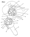
- Fig. 3 the fastening area 9 of mixer 4 is illustrated on an enlarged scale, and mixer tube 18 is visible here.
- Mixer coupling portion 19 is externally provided with a visual coding member 30 in the form of a ridge that can be aligned to visual coding member 15 on the cartridge prior to its attachment.
- mixer coupling portion 19 On its front side, mixer coupling portion 19 has two lift-off ramps 21 that correspond to lift-off ramps 13 on the cartridge.
- two snap segments 22 and 23 are provided whose engagement surfaces 22A, 23A engage behind retaining surfaces 11A and 12A of retaining segments 11 and 12 on the cartridge, see also Fig. 5 .
- At least the engagement surfaces 22A, 23A of the snap segments are also parallel to the corresponding lift-off ramps, see Fig. 4 , and both the snap segments and the lift-off ramps may be continuous or segmented.
- Mixer coupling portion 19 and mixer tube 18 form mixer housing 20 that is arranged rotatably with respect to the inner part 5 of the mixer including the mixing elements, inlets, and inner coding segments.
- an inner coding segment 24 is arranged that has at least one coding slot 25 which corresponds to coding web 17 on the cartridge.
- another coding segment 26 is arranged whose segment length corresponds to the distance between the coding webs 16 on the cartridge.
- coding segment 24 is longer than the distance between coding webs 16.
- the two inlets 27 and 28 of the mixer have different diameters too, inlet 27 having a larger diameter than inlet 28, and these inlets corresponding to outlets 7 and 8 of the cartridge.
- the inlets may alternatively have equal diameters.
- Fig. 4 and partly 5 the exterior of the fastening areas is shown, i.e. mixer coupling portion 19 and a snap segment 22 and on the cartridge, retaining segments 11 and 12, lift-off ramps 13 and stop 14, as well as the visual coding members 15 and 30.
- Fig. 5 is a sectional view according to plane V - V in Fig. 4 that shows the inner cylinder wall 31 of the mixer inlet, in which inner part 5 of the mixer is snapped in so as to be secured in the axial direction but maintained rotatably with respect to this wall and thus with respect to mixer housing 20.
- FIG. 6 shows the elements that have been described above, in particular snap segments 22 and 23 with engagement surfaces 22A, 23A engaging behind retaining surfaces 11A and 12A of retaining segments 11 and 12.
- FIG 7A a simple, one-piece embodiment of a closure cap 32 is depicted in a perspective view.
- Cap housing 33 has a visual coding member 34 and on its open front side two lift-off ramps 35.
- the two closure plugs 36 and 37 have different diameters and are made from a pliable plastics material.
- the two snap segments 38 and 39 are shorter than those of the mixer and therefore require a smaller twisting angle for withdrawal.
- the closure cap is visually aligned and pressed onto the cartridge until the snap segments engage behind the retaining segments. Its removal only requires a small twist to disengage the snap segments. Since the closure plugs are pliable, they are bent and pulled out of the outlets of the cartridge as the cap is twisted off.
- FIGS 7B and 7C show a closure cap 51 having a cap housing 52 provided with the two lift-off ramps 53, visual coding member 34, snap segment 38 and invisible snap segment 39 with engagement surfaces 38A and 39A, as well as coding segments 54 and 55, coding segment 54 having a coding slot 56.
- the sectional view 7C according to plane VIIC - VIIC in Fig. 7B shows the two closure plugs 57 and 58, which are arranged on a base 59 that is snapped in at the bottom 60 of the cap housing and rotatable with respect to the bottom.
- the mixer In order to attach the mixer in the correct orientation, the mixer is first aligned by means of the visual coding members 15 and 30. In this position, the mixer can then be pushed onto the cartridge according to Figure 4 while the snap segments slide on the retaining segments to engage behind the retaining surfaces of the retaining segments at the end of the movement, thereby attaining the position of Fig. 5 .
- coding web 17 engages in coding slot 25, thereby ensuring an additional guidance of the mixer. As follows from the foregoing, if it is attempted to attach the mixer rotated by 180°, the latter cannot be pushed in.
- the mixer For its withdrawal, the mixer is twisted in the counterclockwise direction, whereby the snap segments slide out of the retaining segments and the mixer can be drawn off. During twisting, the lift-off ramps slide on one another and cause the mixer to be lift-off from the cartridge in the longitudinal axis so that the mixer inlets are pulled out of the cartridge outlets.
- mixer housing 20 together with the mixer coupling portion must be twistable with respect to the mixer inlets and the coding segments.
- the entire mixer housing i.e. the mixer coupling portion with the snap segments and the mixer tube is twistable with respect to inner part 5 including the coding segments, inlets, and the mixing element.
- mixer housing twistable with respect to mixer inlet portion 29A with the coding segments only, the mixing element being fixed inside the mixer tube and the latter being sheared off from the mixer inlet portion due to the twisting movement.
- Figure 9 illustrates a variant of the possibilities of an inner coding.
- Double cartridge 40 with the two containers 2 and 3 and outlets 7 and 8 has two opposed coding segments_41 and 42 with coding webs on the inside of its fastening area 40A.
- Coding segment 41 has two end coding webs 43 as well as an intermediate coding web 44, whereas coding segment 42 has two coding webs 45 arranged in its central area.
- mixer 46 In the interior of its fastening area 46A, mixer 46 has corresponding coding segments 47 and 48, coding segment 47 having two coding slots 49 and coding segment 48 one coding slot 50. This arrangement allows a large number of coding possibilities.
- Fig. 10 shows an attachment variant of the mixer of Fig. 9 .
- Mixer 61 has a housing 62 whose lift-off ramps 63 and 64 are not continuous.
- lift-off ramp 63 has a gap 63G or alternatively a plurality of gaps.
- two snap segments 65 and 66 as well as 67 and 68 with the corresponding engagement surfaces 65A - 68A may be provided.
- the inner coding segments and coding webs as well as the inlets are designed according to Fig. 9 .
- mixer 69 with housing 70 of Fig. 11 has respective sets of three snap segments 71, 72, 73 and 74, 75, 76 with the corresponding engagement surfaces 71A - 76A.
- the remaining elements are the same as in the mixer according to Fig. 9 . On this basis, many variations in the design of the ramps and snap segments are possible.
- the accessory is in the form of an adapter, one end thereof is provided with a cartridge fastening area 6 or 40A and the other end with an accessory fastening area 9 or 46A.
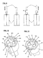
- Figures 12 and 13 show a further exemplary embodiment, where the retaining means are inverted and simplified and the lift-off means also simplified with regard to the previously disclosed embodiments.
- Fig. 12 is analogous to Fig. 3
- Fig. 13 is analogous to Fig. 6 , thus the differences are easily explained by comparing these two pairs of Figures.
- Fig. 12 shows fastening area 81 of cartridge 80 with the two containers 82, 83 on an enlarged scale.
- Attachment socket 84 has two retaining segments 85 and 86 whose cross-section is shown in Fig. 13 , and two lift-off ramps 87. These lift-off ramps are shorter but steeper than the previously shown and have a gradient of about 20° to 35°, preferably about 25° to 33°.
- the fastening area further comprises a visual coding member 88 that is e.g. V-shaped here.
- the inner coding means consists of the different length of the retaining segments, whereby retaining segment 85 is shorter as retaining segment 86.
- a further coding means are the different diameters of the outlets 89 and 90.
- the retaining surfaces 85A and 86A are situated on the inner side of the retaining segments as follows from Fig. 13 .
- the inner upper surfaces 85B and 86B of the retaining segments are inclined.
- Mixer 91 comprises a fastening area 92, a mixer tube 93 and a mixer coupling portion 94 which is externally provided with a visual coding member 95 in the form of a ridge that can be aligned to visual coding member 88 on the cartridge prior to its attachment.
- a visual coding member 95 in the form of a ridge that can be aligned to visual coding member 88 on the cartridge prior to its attachment.
- Within the mixer housing 96 and flush with its front surface two lift-off ribs 97 are provided that cooperate with the lift-off ramps 87 on the cartridge.
- the two snap segments 98 and 99 are arranged on the outside of the coupling portion 94 and whose engagement surfaces 98A and 99A engage behind retaining surfaces 85A and 86A of retaining segments 85 and 86 on the cartridge, see Fig. 13 .
- those parts can be arranged essentially parallel to the front surfaces of the cartridge and accessory, since for disengaging the accessory from the cartridge first the retaining and snap segments disengaged and than the lift-off ribs begin to slide on the lift-off ramps of the cartridge for lifting off the accessory.
- Mixer coupling portion 94 and mixer tube 93 form mixer housing 96 that is arranged rotatably with respect to the inner part 100 of the mixer including the mixing elements, inlets, and inner coding segments.
- the two snap segments have different length, corresponding to the different length of retaining segments 85, 86.
- the two inlets 101 and 102 of the mixer have different diameters too, inlet 101 having a larger diameter than inlet 102, and these inlets corresponding to outlets 89 and 90 of the cartridge.
- the inlets may alternatively have equal diameters. The procedure for fastening the accessory to the cartridge is the same for this embodiment as disclosed above.
Landscapes
- Engineering & Computer Science (AREA)
- Mechanical Engineering (AREA)
- Medical Preparation Storing Or Oral Administration Devices (AREA)
- Package Specialized In Special Use (AREA)
- Infusion, Injection, And Reservoir Apparatuses (AREA)
- Details Of Rigid Or Semi-Rigid Containers (AREA)
- Accessories For Mixers (AREA)
- Closures For Containers (AREA)
Claims (15)
- Ensemble distributeur, incluant une cartouche (1, 40, 80) ou une seringue ayant au moins un conteneur (2, 3) et un accessoire (4, 46, 61, 69, 32, 51, 91), dans lequel la cartouche (1, 40, 80) ou la seringue, d'une part, et l'accessoire (4, 46, 61, 69, 32, 51, 91), d'autre part ont chacun une zone de fixation respective, grâce à quoi la zone de fixation (6, 40A, 81) de la cartouche (1, 40, 80) ou de la seringue et la zone de fixation (9, 46A, 92) de l'accessoire (4, 46, 61, 69 ; 32, 51 ; 91) sont configurées de façon complémentaire et d'une manière telle que l'accessoire (4, 46, 61, 69 ; 32, 51 ; 91) peut être attaché à la cartouche (1, 40, 80) ou à la seringue en emboîtant l'accessoire (4, 46, 61, 69 ; 32, 51 ; 91) sur la cartouche (1, 40, 80) ou sur la seringue sans mouvement tournant, et susceptible d'être enlevé de celle-ci/celui-ci en faisant tourner l'accessoire (4, 46, 61, 69 ; 32, 51 ; 91) par rapport à la cartouche (1, 40, 80) ou à la seringue,
caractérisé en ce que la cartouche (1, 40 ; 80) ou la seringue comprend au moins deux conteneurs (2, 3) avec une sortie (7, 8 ; 89, 90) chacun, et la zone de fixation (6, 40A, 81) de la cartouche (1, 40, 80) ou de la seringue comprend des segments de retenue (11, 12 ; 85, 86) qui sont agencés sur un socle d'attache (10 ; 84), la zone de fixation (6, 40A, 81) de la cartouche (1, 40, 80) ou de la seringue est dotée de rampes de soulèvement (13 ; 63 ; 35 ; 87), et la zone de fixation (9, 46A, 92) de l'accessoire est dotée de rampes de soulèvement correspondantes (21 ; 64 ; 53), ou de nervures de soulèvement (97). - Ensemble distributeur selon la revendication 1, caractérisé en ce que la zone de fixation (9, 46A) de l'accessoire (4, 46, 61, 69 ; 32, 51 ; 91) comprend des segments à encliquetage (22, 23 ; 65, 66, 71, 71, 73 ; 38, 39 ; 98, 99) correspondant aux segments de retenue (11, 12 ; 85, 86) de la cartouche ou de la seringue, les segments à encliquetage étant agencés à l'intérieur de leurs portions de couplage (19 ; 33 ; 94) afin de s'engager, via leurs surfaces d'engagement (; 98A, 99A) derrière les surfaces de retenue (11A, 12A ; 85A, 86A) des segments de retenue.
- Ensemble distributeur selon la revendication 2,
caractérisé en ce que les surfaces de retenue (11A, 12A) sont agencées sur la surface extérieure des segments de retenue (11, 12) au niveau de la cartouche (1) ou de la seringue, et les surfaces d'engagement (22A, 23A ; 65A, 66A, 71A, 71A, 73A ; 38A, 39A de) sont agencées sur la surface intérieure des segments à encliquetage (22, 23 ; 65, 66, 71, 71, 73 ; 38, 39) au niveau des accessoires (20, 32). - Ensemble distributeur selon la revendication 2,
caractérisé en ce que les surfaces de retenue (85A, 86A) sont agencées sur la surface intérieure des segments de retenue (85, 86) au niveau de la cartouche (80) ou de la seringue, et les surfaces d'engagement (98A, 99A) sont agencées sur la surface intérieure des segments à encliquetage (98, 99) au niveau de l'accessoire (91). - Ensemble distributeur selon la revendication 1,
caractérisé en ce que l'angle de gradient des rampes de soulèvement (13 ; 63 ; 35) des surfaces de retenue (11A, 12A) des segments de retenue (11, 12), et des surfaces d'engagement (22A, 23A ; 65A, 66A, 71A, 71A, 73A ; 38A, 39A) sur la surface intérieure des segments à encliquetage (22, 23 ; 65, 66, 71, 71, 73 ; 38, 39) est compris dans une plage de 1 ° à 30°, de préférence de 3° à 10°. - Ensemble distributeur selon la revendication 1,
caractérisé en ce que l'angle de gradient des rampes de soulèvement (87) des segments de retenue (85, 86) est compris dans une plage de 20° à 35°, de préférence de 25° à 33°. - Ensemble distributeur selon la revendication 5,
caractérisé en ce que les surfaces de retenue (11A, 12A) des segments de retenue (11, 12) et les surfaces d'engagement (22A, 23A ; 65A, 66A, 71A, 71A, 73A ; 38A, 39A) des segments à encliquetage (22, 23, 38, 39) sont agencées sensiblement parallèlement aux rampes de soulèvement. - Ensemble distributeur selon l'une quelconque des revendications 1 à 7, caractérisé en ce que les segments de retenue, les segments d'encliquetage, et les rampes de soulèvement sont sans interruption ou segmentés.
- Ensemble distributeur selon l'une quelconque des revendications 1 à 8, caractérisé en ce que la cartouche ou la seringue et l'accessoire comprennent des moyens de codage visuel (15 ; 30 ; 34 ; 88, 85) pour aligner les parties les unes par rapport aux autres.
- Ensemble distributeur selon l'une quelconque des revendications 1 à 9, caractérisé en ce que la cartouche ou la seringue et l'accessoire ont des éléments de codage (7, 8 ; 27, 28 ; 36, 37 ; 16, 17 ; 24-26 ; 41-45 ; 47-50 ; 89, 90 ; 101, 102) afin d'empêcher un attachement de l'accessoire sur la cartouche ou sur la seringue sous la mauvaise orientation ou l'attachement d'un accessoire inapproprié.
- Ensemble distributeur selon la revendication 10,
caractérisé en ce que les éléments de codage de la cartouche (1, 40) ou de la seringue incluent des segments de codage (41, 42), et des pattes de codage (16, 17 ; 43-45) qui sont agencées à l'intérieur du socle d'attachement (13), et des segments de codage correspondants (24, 26, 47, 48, 54, 55) et au moins une fente de codage (25, 49, 50, 51) sur l'accessoire (4, 46, 61, 69, 51). - Ensemble distributeur selon la revendication 10 ou 11, caractérisé en ce que les éléments de codage de la cartouche ou de la seringue incluent des sorties (7, 8 ; 89, 90) de diamètres différents et ceux de l'accessoire incluent des entrées (27, 28 ; 101, 102) ou des bouchons de fermeture (36, 37 ; 57, 58) de diamètres différents correspondants.
- Ensemble distributeur selon l'une quelconque des revendications 1 à 12, caractérisé en ce que l'accessoire est un mélangeur (4, 46, 61, 69, 91) et le boîtier (20, 62, 70, 96) du mélangeur incluant les segments à encliquetage (22, 23 ; 65, 66, 71, 71, 73 ; 98, 99) est capable de rotation autour de sa partie intérieure (5, 100), ou au moins autour de la portion d'entrée (29A) du mélangeur, respectivement.
- Ensemble distributeur selon l'une quelconque des revendications 1 à 13, caractérisé en ce que l'accessoire est un capuchon de fermeture (32) ayant des bouchons de fermeture souples (36, 37).
- Ensemble distributeur selon l'une quelconque des revendications 1 à 14, caractérisé en ce que l'accessoire est un capuchon de fermeture (51) dont les bouchons de fermeture (57, 58) sont agencés en rotation par rapport au boîtier de capuchon (52).
Applications Claiming Priority (2)
| Application Number | Priority Date | Filing Date | Title |
|---|---|---|---|
| CH4332007 | 2007-03-19 | ||
| PCT/CH2008/000110 WO2008113196A1 (fr) | 2007-03-19 | 2008-03-17 | Ensemble de distribution équipé d'accessoires fixés amovibles |
Publications (2)
| Publication Number | Publication Date |
|---|---|
| EP2139786A1 EP2139786A1 (fr) | 2010-01-06 |
| EP2139786B1 true EP2139786B1 (fr) | 2014-04-30 |
Family
ID=38190834
Family Applications (1)
| Application Number | Title | Priority Date | Filing Date |
|---|---|---|---|
| EP08714760.9A Not-in-force EP2139786B1 (fr) | 2007-03-19 | 2008-03-17 | Ensemble de distribution equipe d'accessoires fixes amovibles |
Country Status (12)
| Country | Link |
|---|---|
| US (1) | US8376187B2 (fr) |
| EP (1) | EP2139786B1 (fr) |
| JP (1) | JP2010521384A (fr) |
| KR (1) | KR101487863B1 (fr) |
| CN (1) | CN101668689B (fr) |
| AU (1) | AU2008229561B2 (fr) |
| BR (1) | BRPI0808932B1 (fr) |
| CA (1) | CA2681178C (fr) |
| ES (1) | ES2462942T3 (fr) |
| IL (1) | IL200910A (fr) |
| RU (1) | RU2431591C2 (fr) |
| WO (1) | WO2008113196A1 (fr) |
Families Citing this family (38)
| Publication number | Priority date | Publication date | Assignee | Title |
|---|---|---|---|---|
| JP5172185B2 (ja) * | 2007-03-22 | 2013-03-27 | 株式会社ジーシー | ミキシングチップ |
| DE102007000850A1 (de) | 2007-10-11 | 2009-04-16 | Hilti Aktiengesellschaft | Kartusche für eine auspressbare Masse |
| EP2279021B1 (fr) * | 2008-04-18 | 2013-02-13 | Kuros Biosurgery AG | Dispositif de distribution, ensemble contenant le dispositif, et procédé d'utilisation du dispositif |
| IT1391454B1 (it) * | 2008-09-26 | 2011-12-23 | Lameplast Spa | Contenitore per prodotti fluidi, particolarmente farmaceutici, cosmetici, alimentari o simili |
| DE102009041639A1 (de) * | 2009-09-17 | 2011-03-24 | Friedrich Sanner Gmbh & Co. Kg | Behälter zur Bereitstellung einer Zweikompentenmischung |
| WO2011041917A1 (fr) | 2009-10-06 | 2011-04-14 | Medmix Systems Ag | Système de décharge avec un système de liaison entre une cartouche multicomposant et un accessoire |
| USD743046S1 (en) * | 2009-10-12 | 2015-11-10 | Medsmart, Llc | Fecal sample collection device |
| CN102211067A (zh) * | 2010-04-09 | 2011-10-12 | 何弘一 | 药剂混合装置 |
| US9770524B2 (en) | 2010-07-16 | 2017-09-26 | S. C. Johnson & Son, Inc. | Volatile material dispenser and method of attaching a refill or refills to same |
| CA2746283A1 (fr) * | 2010-09-10 | 2012-03-10 | Sulzer Mixpac Ag | Dispositif de fermeture a l'epreuve des enfants pour appareil de distribution |
| WO2012055926A1 (fr) * | 2010-10-26 | 2012-05-03 | Kettenbach Gmbh & Co. Kg | Cartouche double, mélangeur destiné à celle-ci et combinaison cartouche double et mélangeur |
| DE102010060671B4 (de) * | 2010-11-19 | 2016-12-08 | Ritter Gmbh | Integrierter Radialer Zapfenverschluss für Mehrkomponentenkartuschen mit Mischer |
| EP2468416A1 (fr) * | 2010-12-24 | 2012-06-27 | Sika Technology AG | Dispositif d'application pour matières à plusieurs composants, ensemble de cartouche et unité d'emballage |
| DK2520360T3 (da) * | 2011-05-02 | 2014-09-01 | Sulzer Mixpac Ag | Blandemaskine til blanding af mindst to flydedygtige komponenter samt udledningsanordning |
| CA2838293C (fr) | 2011-06-06 | 2018-09-18 | Sulzer Mixpac Ag | Ensemble de cartouches a plusieurs composants |
| JP5881991B2 (ja) * | 2011-07-29 | 2016-03-09 | 株式会社ジーシー | ダブルシリンジ |
| WO2013026717A1 (fr) * | 2011-08-24 | 2013-02-28 | Kettenbach Gmbh & Co. Kg | Système de cartouche et mélangeur statique associé |
| WO2013026716A1 (fr) * | 2011-08-24 | 2013-02-28 | Kettenbach Gmbh & Co. Kg | Système composé de cartouches et de mélangeurs |
| CN102988103A (zh) * | 2011-09-14 | 2013-03-27 | 南京医科大学第二附属医院 | 一种用于添加生物活性因子或药物的搅拌注射器 |
| CA2789725C (fr) | 2011-11-29 | 2019-08-06 | Sulzer Mixpac Ag | Element melangeur pour melangeur statique |
| CA2787737C (fr) * | 2011-12-22 | 2019-04-30 | Sulzer Mixpac Ag | Dispositif distributeur pour cartouches a plusieurs composants |
| US8919609B2 (en) * | 2012-01-10 | 2014-12-30 | Pac-Dent International, Inc. | Dental mixing device having an auto-aligning tip mixing tip |
| CN104582823B (zh) * | 2012-08-21 | 2017-02-22 | 药物混合系统股份公司 | 用于排料单元的混合设备 |
| US9138772B2 (en) | 2012-10-31 | 2015-09-22 | Nordson Corporation | Dispensing assembly and method using snap engagement of a mixer and a cartridge |
| US9289797B2 (en) * | 2012-11-06 | 2016-03-22 | Nordson Corporation | Dispensing assembly and method for assembling a dispenser and dispensing a fluid |
| KR102023143B1 (ko) * | 2012-11-08 | 2019-09-19 | 술저 믹스팩 아게 | 2개 이상의 유동성 성분을 위한 카트리지 |
| EP2959861A1 (fr) | 2014-06-23 | 2015-12-30 | Sulzer Mixpac AG | Seringues d'administration de produit multi-composant |
| EP3188847B1 (fr) * | 2014-09-02 | 2020-01-08 | Sika Technology AG | Appareil d'application de compositions en gel et/ou pâteuses et dispositif d'application pour un tel appareil d'application |
| US10099838B2 (en) * | 2015-04-13 | 2018-10-16 | Nordson Corporation | Fluid cartridge system and method of using a fluid cartridge system |
| US9827539B2 (en) * | 2015-07-31 | 2017-11-28 | Phillip Phung-I Ho | Dynamic mixer head |
| ES2934154T3 (es) * | 2015-10-30 | 2023-02-17 | Medmix Switzerland Ag | Mezclador estático |
| US10281074B2 (en) | 2016-01-14 | 2019-05-07 | Nordson Corporation | Adapters for connecting a separated-outlet fluid cartridge to a single-inlet mixer, and related methods |
| USD792177S1 (en) * | 2016-02-25 | 2017-07-18 | Phillip Phung-I Ho | Head for a dual-cartridge dispenser |
| US10641423B2 (en) * | 2016-06-09 | 2020-05-05 | Nordson Corporation | Adapters for connecting a separated-outlet fluid cartridge to a single-inlet mixer, and related methods |
| DE102017117557A1 (de) | 2017-08-02 | 2019-02-07 | 3lmed GmbH | Applikationssystem |
| CN107952633B (zh) * | 2017-08-18 | 2021-10-29 | 昆山市双组份国际贸易有限公司 | 一种打胶装置 |
| DE102019101651A1 (de) | 2019-01-23 | 2020-07-23 | 3lmed GmbH | Applikationssystem mit verbesserter Dichtung |
| US11872535B2 (en) * | 2020-01-03 | 2024-01-16 | Huanghua Promisee Dental Co., Ltd. | Connecting chuck of material cylinder for mixer and mixer |
Family Cites Families (15)
| Publication number | Priority date | Publication date | Assignee | Title |
|---|---|---|---|---|
| JPH0531079Y2 (fr) * | 1986-05-21 | 1993-08-10 | ||
| CH681146A5 (fr) * | 1990-07-20 | 1993-01-29 | Wilhelm A Keller | |
| FR2704527B1 (fr) * | 1993-04-26 | 1995-06-30 | Oreal | Combinaison d'une batterie de recipients et d'une barrette de capuchons, et ensemble d'un recipient et d'un capuchon. |
| EP1125641B1 (fr) * | 1995-03-07 | 2003-05-02 | Wilhelm A. Keller | Dispositif de fixation à bayonnette pour attacher un accessoire à une cartouche à composants multiples ou dispositif distributeur |
| US5918772A (en) * | 1995-03-13 | 1999-07-06 | Wilhelm A. Keller | Bayonet fastening device for the attachment of an accessory to a multiple component cartridge or dispensing device |
| DE29709383U1 (de) * | 1997-05-28 | 1998-10-08 | THERA Patent GmbH & Co. KG Gesellschaft für industrielle Schutzrechte, 82229 Seefeld | Behälter für pastöse Massen |
| CN2433215Y (zh) * | 2000-07-31 | 2001-06-06 | 秦家平 | 双腔包装瓶 |
| RU17287U1 (ru) * | 2000-09-20 | 2001-03-27 | Закрытое акционерное общество "Краски Маршал-Рус" | Шприц для дозированной подачи красителя |
| DE10258953A1 (de) * | 2002-12-16 | 2004-07-22 | S&C Polymer Silicon- und Composite-Spezialitäten GmbH | Abgabevorrichtung für fluide Substanzen |
| US7694853B2 (en) * | 2003-09-01 | 2010-04-13 | Mixpac Systems Ag | Dispensing device comprising a stopper and locking ring with bayonet coupling means |
| IE20040076A1 (en) * | 2004-02-09 | 2005-08-10 | Loctite R & D Ltd | A dispensing nozzle and cap |
| EP1763405B1 (fr) * | 2004-07-08 | 2011-10-19 | Sulzer Mixpac AG | Dispositif de deversement comprenant une seringue ou une cartouche, un capuchon de fermeture et un melangeur |
| DE502004010975D1 (de) * | 2004-07-16 | 2010-05-12 | Dentaco Gmbh | Mehrkammerampulle zum Ausgeben eines aus mehreren Substanzen bestehenden Gemisches |
| DE502005009314D1 (de) | 2005-05-18 | 2010-05-12 | Dentaco Gmbh | Mehrkammerausgabevorrichtung |
| ATE443007T1 (de) * | 2005-07-22 | 2009-10-15 | Dentaco Gmbh | Mehrkammerausgabevorrichtung |
-
2008
- 2008-03-17 WO PCT/CH2008/000110 patent/WO2008113196A1/fr not_active Ceased
- 2008-03-17 EP EP08714760.9A patent/EP2139786B1/fr not_active Not-in-force
- 2008-03-17 US US12/530,873 patent/US8376187B2/en not_active Expired - Fee Related
- 2008-03-17 RU RU2009138326/12A patent/RU2431591C2/ru not_active IP Right Cessation
- 2008-03-17 ES ES08714760.9T patent/ES2462942T3/es active Active
- 2008-03-17 CN CN200880008787.9A patent/CN101668689B/zh not_active Expired - Fee Related
- 2008-03-17 CA CA2681178A patent/CA2681178C/fr not_active Expired - Fee Related
- 2008-03-17 JP JP2009553882A patent/JP2010521384A/ja active Pending
- 2008-03-17 AU AU2008229561A patent/AU2008229561B2/en not_active Ceased
- 2008-03-17 BR BRPI0808932-9A patent/BRPI0808932B1/pt not_active IP Right Cessation
- 2008-03-17 KR KR1020097019326A patent/KR101487863B1/ko not_active Expired - Fee Related
-
2009
- 2009-09-14 IL IL200910A patent/IL200910A/en active IP Right Grant
Also Published As
| Publication number | Publication date |
|---|---|
| WO2008113196A1 (fr) | 2008-09-25 |
| KR20090121340A (ko) | 2009-11-25 |
| US8376187B2 (en) | 2013-02-19 |
| KR101487863B1 (ko) | 2015-01-29 |
| CA2681178A1 (fr) | 2008-09-25 |
| RU2009138326A (ru) | 2011-04-27 |
| CN101668689B (zh) | 2014-02-19 |
| CA2681178C (fr) | 2015-02-17 |
| ES2462942T3 (es) | 2014-05-26 |
| AU2008229561B2 (en) | 2013-05-16 |
| US20100102088A1 (en) | 2010-04-29 |
| BRPI0808932B1 (pt) | 2019-04-02 |
| BRPI0808932A2 (pt) | 2014-10-14 |
| EP2139786A1 (fr) | 2010-01-06 |
| IL200910A (en) | 2015-11-30 |
| JP2010521384A (ja) | 2010-06-24 |
| AU2008229561A1 (en) | 2008-09-25 |
| CN101668689A (zh) | 2010-03-10 |
| IL200910A0 (en) | 2010-05-17 |
| RU2431591C2 (ru) | 2011-10-20 |
Similar Documents
| Publication | Publication Date | Title |
|---|---|---|
| EP2139786B1 (fr) | Ensemble de distribution equipe d'accessoires fixes amovibles | |
| KR101891954B1 (ko) | 다중 성분 분배 카트리지, 혼합용 노즐 및 유체들 간의 접촉을 줄이기 위한 방법 | |
| EP2018132B1 (fr) | Dispositif de distribution doté d'un ensemble de pulvérisation | |
| US7316330B2 (en) | Dispensing system for fluid substances | |
| EP2593236B1 (fr) | Récipient de liquide pour un dispositif de revêtement par pulvérisation | |
| EP1083005A2 (fr) | Buse de mélange pour mélanger statique et configuration de la zone de liaison d'accesoires | |
| US11168821B2 (en) | Adapters for connecting a separated-outlet fluid cartridge to a single-inlet mixer, and related methods | |
| US8672188B2 (en) | Intermediate piece for the connection of a storage container to a static mixer | |
| US6161730A (en) | Apparatus for carrying out a mixing dispensing of a plurality of flowable components | |
| KR102349558B1 (ko) | 분리형-출구 유체 카트리지를 단일-입구 혼합기에 연결하기 위한 어댑터, 및 관련 방법 | |
| US20080029542A1 (en) | Dispensing Assembly for Two Components , Including a Syringe or Dispensing Cartidge and a Mixer | |
| US9272252B2 (en) | System composed of cartridges and mixers | |
| US20110138741A1 (en) | Dispensing assembly comprising a cartridge with bag | |
| JP2008504956A (ja) | 注射器又はカートリッジ、クロージング・キャップ、及び混合器を含む分配システム | |
| KR20000036087A (ko) | 디스펜싱 카트리지 | |
| US6328182B1 (en) | Two-component cartridge | |
| US8894270B2 (en) | Mixing system for two-component cartridge | |
| CN121001812A (zh) | 用于双组分化合物料筒的混合器适配器以及配备该适配器的混合器-料筒组件 | |
| AU2015201231B2 (en) | System comprising a spray coating device with a liquid supply container |
Legal Events
| Date | Code | Title | Description |
|---|---|---|---|
| PUAI | Public reference made under article 153(3) epc to a published international application that has entered the european phase |
Free format text: ORIGINAL CODE: 0009012 |
|
| 17P | Request for examination filed |
Effective date: 20091019 |
|
| AK | Designated contracting states |
Kind code of ref document: A1 Designated state(s): AT BE BG CH CY CZ DE DK EE ES FI FR GB GR HR HU IE IS IT LI LT LU LV MC MT NL NO PL PT RO SE SI SK TR |
|
| DAX | Request for extension of the european patent (deleted) | ||
| 17Q | First examination report despatched |
Effective date: 20121102 |
|
| GRAP | Despatch of communication of intention to grant a patent |
Free format text: ORIGINAL CODE: EPIDOSNIGR1 |
|
| INTG | Intention to grant announced |
Effective date: 20140127 |
|
| RIN1 | Information on inventor provided before grant (corrected) |
Inventor name: KELLER, WILHELM, A. |
|
| GRAS | Grant fee paid |
Free format text: ORIGINAL CODE: EPIDOSNIGR3 |
|
| GRAA | (expected) grant |
Free format text: ORIGINAL CODE: 0009210 |
|
| AK | Designated contracting states |
Kind code of ref document: B1 Designated state(s): AT BE BG CH CY CZ DE DK EE ES FI FR GB GR HR HU IE IS IT LI LT LU LV MC MT NL NO PL PT RO SE SI SK TR |
|
| REG | Reference to a national code |
Ref country code: GB Ref legal event code: FG4D Ref country code: CH Ref legal event code: EP Ref country code: CH Ref legal event code: NV Representative=s name: DR. GRAF AND PARTNER AG INTELLECTUAL PROPERTY, CH |
|
| REG | Reference to a national code |
Ref country code: AT Ref legal event code: REF Ref document number: 664958 Country of ref document: AT Kind code of ref document: T Effective date: 20140515 |
|
| REG | Reference to a national code |
Ref country code: IE Ref legal event code: FG4D |
|
| REG | Reference to a national code |
Ref country code: ES Ref legal event code: FG2A Ref document number: 2462942 Country of ref document: ES Kind code of ref document: T3 Effective date: 20140526 |
|
| REG | Reference to a national code |
Ref country code: DE Ref legal event code: R096 Ref document number: 602008031852 Country of ref document: DE Effective date: 20140612 |
|
| REG | Reference to a national code |
Ref country code: AT Ref legal event code: MK05 Ref document number: 664958 Country of ref document: AT Kind code of ref document: T Effective date: 20140430 |
|
| REG | Reference to a national code |
Ref country code: LT Ref legal event code: MG4D |
|
| REG | Reference to a national code |
Ref country code: NL Ref legal event code: VDEP Effective date: 20140430 |
|
| PG25 | Lapsed in a contracting state [announced via postgrant information from national office to epo] |
Ref country code: IS Free format text: LAPSE BECAUSE OF FAILURE TO SUBMIT A TRANSLATION OF THE DESCRIPTION OR TO PAY THE FEE WITHIN THE PRESCRIBED TIME-LIMIT Effective date: 20140830 Ref country code: NL Free format text: LAPSE BECAUSE OF FAILURE TO SUBMIT A TRANSLATION OF THE DESCRIPTION OR TO PAY THE FEE WITHIN THE PRESCRIBED TIME-LIMIT Effective date: 20140430 Ref country code: FI Free format text: LAPSE BECAUSE OF FAILURE TO SUBMIT A TRANSLATION OF THE DESCRIPTION OR TO PAY THE FEE WITHIN THE PRESCRIBED TIME-LIMIT Effective date: 20140430 Ref country code: BG Free format text: LAPSE BECAUSE OF FAILURE TO SUBMIT A TRANSLATION OF THE DESCRIPTION OR TO PAY THE FEE WITHIN THE PRESCRIBED TIME-LIMIT Effective date: 20140730 Ref country code: CY Free format text: LAPSE BECAUSE OF FAILURE TO SUBMIT A TRANSLATION OF THE DESCRIPTION OR TO PAY THE FEE WITHIN THE PRESCRIBED TIME-LIMIT Effective date: 20140430 Ref country code: NO Free format text: LAPSE BECAUSE OF FAILURE TO SUBMIT A TRANSLATION OF THE DESCRIPTION OR TO PAY THE FEE WITHIN THE PRESCRIBED TIME-LIMIT Effective date: 20140730 Ref country code: GR Free format text: LAPSE BECAUSE OF FAILURE TO SUBMIT A TRANSLATION OF THE DESCRIPTION OR TO PAY THE FEE WITHIN THE PRESCRIBED TIME-LIMIT Effective date: 20140731 Ref country code: LT Free format text: LAPSE BECAUSE OF FAILURE TO SUBMIT A TRANSLATION OF THE DESCRIPTION OR TO PAY THE FEE WITHIN THE PRESCRIBED TIME-LIMIT Effective date: 20140430 |
|
| PG25 | Lapsed in a contracting state [announced via postgrant information from national office to epo] |
Ref country code: HR Free format text: LAPSE BECAUSE OF FAILURE TO SUBMIT A TRANSLATION OF THE DESCRIPTION OR TO PAY THE FEE WITHIN THE PRESCRIBED TIME-LIMIT Effective date: 20140430 Ref country code: SE Free format text: LAPSE BECAUSE OF FAILURE TO SUBMIT A TRANSLATION OF THE DESCRIPTION OR TO PAY THE FEE WITHIN THE PRESCRIBED TIME-LIMIT Effective date: 20140430 Ref country code: AT Free format text: LAPSE BECAUSE OF FAILURE TO SUBMIT A TRANSLATION OF THE DESCRIPTION OR TO PAY THE FEE WITHIN THE PRESCRIBED TIME-LIMIT Effective date: 20140430 Ref country code: PL Free format text: LAPSE BECAUSE OF FAILURE TO SUBMIT A TRANSLATION OF THE DESCRIPTION OR TO PAY THE FEE WITHIN THE PRESCRIBED TIME-LIMIT Effective date: 20140430 Ref country code: LV Free format text: LAPSE BECAUSE OF FAILURE TO SUBMIT A TRANSLATION OF THE DESCRIPTION OR TO PAY THE FEE WITHIN THE PRESCRIBED TIME-LIMIT Effective date: 20140430 |
|
| PG25 | Lapsed in a contracting state [announced via postgrant information from national office to epo] |
Ref country code: PT Free format text: LAPSE BECAUSE OF FAILURE TO SUBMIT A TRANSLATION OF THE DESCRIPTION OR TO PAY THE FEE WITHIN THE PRESCRIBED TIME-LIMIT Effective date: 20140901 |
|
| PG25 | Lapsed in a contracting state [announced via postgrant information from national office to epo] |
Ref country code: BE Free format text: LAPSE BECAUSE OF FAILURE TO SUBMIT A TRANSLATION OF THE DESCRIPTION OR TO PAY THE FEE WITHIN THE PRESCRIBED TIME-LIMIT Effective date: 20140430 Ref country code: SK Free format text: LAPSE BECAUSE OF FAILURE TO SUBMIT A TRANSLATION OF THE DESCRIPTION OR TO PAY THE FEE WITHIN THE PRESCRIBED TIME-LIMIT Effective date: 20140430 Ref country code: EE Free format text: LAPSE BECAUSE OF FAILURE TO SUBMIT A TRANSLATION OF THE DESCRIPTION OR TO PAY THE FEE WITHIN THE PRESCRIBED TIME-LIMIT Effective date: 20140430 Ref country code: DK Free format text: LAPSE BECAUSE OF FAILURE TO SUBMIT A TRANSLATION OF THE DESCRIPTION OR TO PAY THE FEE WITHIN THE PRESCRIBED TIME-LIMIT Effective date: 20140430 Ref country code: CZ Free format text: LAPSE BECAUSE OF FAILURE TO SUBMIT A TRANSLATION OF THE DESCRIPTION OR TO PAY THE FEE WITHIN THE PRESCRIBED TIME-LIMIT Effective date: 20140430 Ref country code: RO Free format text: LAPSE BECAUSE OF FAILURE TO SUBMIT A TRANSLATION OF THE DESCRIPTION OR TO PAY THE FEE WITHIN THE PRESCRIBED TIME-LIMIT Effective date: 20140430 |
|
| REG | Reference to a national code |
Ref country code: DE Ref legal event code: R097 Ref document number: 602008031852 Country of ref document: DE |
|
| PLBE | No opposition filed within time limit |
Free format text: ORIGINAL CODE: 0009261 |
|
| STAA | Information on the status of an ep patent application or granted ep patent |
Free format text: STATUS: NO OPPOSITION FILED WITHIN TIME LIMIT |
|
| 26N | No opposition filed |
Effective date: 20150202 |
|
| REG | Reference to a national code |
Ref country code: DE Ref legal event code: R097 Ref document number: 602008031852 Country of ref document: DE Effective date: 20150202 |
|
| PG25 | Lapsed in a contracting state [announced via postgrant information from national office to epo] |
Ref country code: SI Free format text: LAPSE BECAUSE OF FAILURE TO SUBMIT A TRANSLATION OF THE DESCRIPTION OR TO PAY THE FEE WITHIN THE PRESCRIBED TIME-LIMIT Effective date: 20140430 |
|
| PG25 | Lapsed in a contracting state [announced via postgrant information from national office to epo] |
Ref country code: LU Free format text: LAPSE BECAUSE OF FAILURE TO SUBMIT A TRANSLATION OF THE DESCRIPTION OR TO PAY THE FEE WITHIN THE PRESCRIBED TIME-LIMIT Effective date: 20150317 Ref country code: MC Free format text: LAPSE BECAUSE OF FAILURE TO SUBMIT A TRANSLATION OF THE DESCRIPTION OR TO PAY THE FEE WITHIN THE PRESCRIBED TIME-LIMIT Effective date: 20140430 |
|
| REG | Reference to a national code |
Ref country code: IE Ref legal event code: MM4A |
|
| PG25 | Lapsed in a contracting state [announced via postgrant information from national office to epo] |
Ref country code: IE Free format text: LAPSE BECAUSE OF NON-PAYMENT OF DUE FEES Effective date: 20150317 |
|
| REG | Reference to a national code |
Ref country code: FR Ref legal event code: PLFP Year of fee payment: 9 |
|
| PG25 | Lapsed in a contracting state [announced via postgrant information from national office to epo] |
Ref country code: MT Free format text: LAPSE BECAUSE OF FAILURE TO SUBMIT A TRANSLATION OF THE DESCRIPTION OR TO PAY THE FEE WITHIN THE PRESCRIBED TIME-LIMIT Effective date: 20140430 |
|
| REG | Reference to a national code |
Ref country code: FR Ref legal event code: PLFP Year of fee payment: 10 |
|
| PG25 | Lapsed in a contracting state [announced via postgrant information from national office to epo] |
Ref country code: HU Free format text: LAPSE BECAUSE OF FAILURE TO SUBMIT A TRANSLATION OF THE DESCRIPTION OR TO PAY THE FEE WITHIN THE PRESCRIBED TIME-LIMIT; INVALID AB INITIO Effective date: 20080317 |
|
| REG | Reference to a national code |
Ref country code: FR Ref legal event code: PLFP Year of fee payment: 11 |
|
| PGFP | Annual fee paid to national office [announced via postgrant information from national office to epo] |
Ref country code: CH Payment date: 20180321 Year of fee payment: 11 |
|
| PGFP | Annual fee paid to national office [announced via postgrant information from national office to epo] |
Ref country code: TR Payment date: 20180315 Year of fee payment: 11 Ref country code: FR Payment date: 20180330 Year of fee payment: 11 |
|
| PGFP | Annual fee paid to national office [announced via postgrant information from national office to epo] |
Ref country code: ES Payment date: 20180430 Year of fee payment: 11 |
|
| PGFP | Annual fee paid to national office [announced via postgrant information from national office to epo] |
Ref country code: IT Payment date: 20180327 Year of fee payment: 11 |
|
| PGFP | Annual fee paid to national office [announced via postgrant information from national office to epo] |
Ref country code: GB Payment date: 20190320 Year of fee payment: 12 |
|
| REG | Reference to a national code |
Ref country code: CH Ref legal event code: PL |
|
| PG25 | Lapsed in a contracting state [announced via postgrant information from national office to epo] |
Ref country code: LI Free format text: LAPSE BECAUSE OF NON-PAYMENT OF DUE FEES Effective date: 20190331 Ref country code: CH Free format text: LAPSE BECAUSE OF NON-PAYMENT OF DUE FEES Effective date: 20190331 |
|
| PG25 | Lapsed in a contracting state [announced via postgrant information from national office to epo] |
Ref country code: FR Free format text: LAPSE BECAUSE OF NON-PAYMENT OF DUE FEES Effective date: 20190331 Ref country code: IT Free format text: LAPSE BECAUSE OF NON-PAYMENT OF DUE FEES Effective date: 20190317 |
|
| PGFP | Annual fee paid to national office [announced via postgrant information from national office to epo] |
Ref country code: DE Payment date: 20200320 Year of fee payment: 13 |
|
| REG | Reference to a national code |
Ref country code: ES Ref legal event code: FD2A Effective date: 20200727 |
|
| PG25 | Lapsed in a contracting state [announced via postgrant information from national office to epo] |
Ref country code: ES Free format text: LAPSE BECAUSE OF NON-PAYMENT OF DUE FEES Effective date: 20190318 |
|
| GBPC | Gb: european patent ceased through non-payment of renewal fee |
Effective date: 20200317 |
|
| PG25 | Lapsed in a contracting state [announced via postgrant information from national office to epo] |
Ref country code: GB Free format text: LAPSE BECAUSE OF NON-PAYMENT OF DUE FEES Effective date: 20200317 |
|
| REG | Reference to a national code |
Ref country code: DE Ref legal event code: R119 Ref document number: 602008031852 Country of ref document: DE |
|
| PG25 | Lapsed in a contracting state [announced via postgrant information from national office to epo] |
Ref country code: DE Free format text: LAPSE BECAUSE OF NON-PAYMENT OF DUE FEES Effective date: 20211001 |
|
| PG25 | Lapsed in a contracting state [announced via postgrant information from national office to epo] |
Ref country code: TR Free format text: LAPSE BECAUSE OF NON-PAYMENT OF DUE FEES Effective date: 20190317 |