EP2139092A1 - Elektrische drehmaschine - Google Patents
Elektrische drehmaschine Download PDFInfo
- Publication number
- EP2139092A1 EP2139092A1 EP07737078A EP07737078A EP2139092A1 EP 2139092 A1 EP2139092 A1 EP 2139092A1 EP 07737078 A EP07737078 A EP 07737078A EP 07737078 A EP07737078 A EP 07737078A EP 2139092 A1 EP2139092 A1 EP 2139092A1
- Authority
- EP
- European Patent Office
- Prior art keywords
- rotor
- portions
- magnetic pole
- electric machine
- rotating electric
- Prior art date
- Legal status (The legal status is an assumption and is not a legal conclusion. Google has not performed a legal analysis and makes no representation as to the accuracy of the status listed.)
- Withdrawn
Links
Images


Classifications
-
- H—ELECTRICITY
- H02—GENERATION; CONVERSION OR DISTRIBUTION OF ELECTRIC POWER
- H02K—DYNAMO-ELECTRIC MACHINES
- H02K1/00—Details of the magnetic circuit
- H02K1/06—Details of the magnetic circuit characterised by the shape, form or construction
- H02K1/22—Rotating parts of the magnetic circuit
- H02K1/26—Rotor cores with slots for windings
- H02K1/265—Shape, form or location of the slots
-
- H—ELECTRICITY
- H02—GENERATION; CONVERSION OR DISTRIBUTION OF ELECTRIC POWER
- H02K—DYNAMO-ELECTRIC MACHINES
- H02K1/00—Details of the magnetic circuit
- H02K1/06—Details of the magnetic circuit characterised by the shape, form or construction
- H02K1/22—Rotating parts of the magnetic circuit
- H02K1/32—Rotating parts of the magnetic circuit with channels or ducts for flow of cooling medium
-
- H—ELECTRICITY
- H02—GENERATION; CONVERSION OR DISTRIBUTION OF ELECTRIC POWER
- H02K—DYNAMO-ELECTRIC MACHINES
- H02K3/00—Details of windings
- H02K3/04—Windings characterised by the conductor shape, form or construction, e.g. with bar conductors
- H02K3/24—Windings characterised by the conductor shape, form or construction, e.g. with bar conductors with channels or ducts for cooling medium between the conductors
Definitions
- the present invention relates to a rotating electric machine such as a generator and, more particularly, to a rotating electric machine having an improved shape of rotor slots.
- a typical rotating electric machine such as a generator includes a hollow cylindrical stator constructed by winding armature coils around a stator core and a rotor having a diameter slightly smaller than the diameter of the hollow cylindrical portion of the stator and constructed by winding field coils in a layered fashion around the cylindrical rotor core.
- the rotor is positioned within the stator in a co-axial manner with the stator.
- the stator and rotor each has a core.
- An armature coil and a field coil which are each a coil of electrically conductive bars such as copper wires, are provided in each of slots formed in the cores in the axial direction of each slot.
- the rotor is rotated in a state where a DC power is supplied from an excitation power source to excite the coils on the rotor side, i.e., the field coils. This induces a voltage in the stator and thereby an electric power is generated.
- the core of the rotor is generally made from a single steel block so as to ensure mechanical strength against centrifugal force caused at the time of rotation of the rotor.
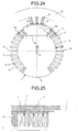
- FIG. 24 is a cross-sectional view of a conventional rotating electric machine.
- reference numeral "1" denotes a rotor core of a rotating electric machine.
- the rotor core 1 has substantially a circular cross-section and is disposed within a stator core 16 around which an armature coil 15 is wound in a co-axial manner with the same.
- a predetermined space is interposed between the rotor core 1 and stator core 16.
- At least one pair of magnetic pole portions 2 and 2 between which a field flux ⁇ passes are formed at positions on the outer circumference of the rotor core 1 across the center point of the rotor core 1.
- the area other than the magnetic pole portions 2 and 2 serves as a non-polar portion 3.
- a plurality of rotor slots 4 for housing not-shown field coils are formed at predetermined intervals in the non-polar portions 3.
- Reference numeral "5" denotes a rotor tooth portion formed between the slots 4.
- the number of rotor slots 4 for each pole is an integer, so that an interpolar portion 6 is formed in the non-polar portion 3 at substantially the center of the intermediate portion between the pair of magnetic pole portions 2 and 2.
- Field coils 7 are housed in the rotor slots 4, and rotor wedges 17 for coils retention are inserted on the outer diameter side of the field coils 7 so as to retain the field coils 7 against centrifugal force caused at the time of rotation of the rotor.
- the rotor coils 7 are electrically serially connected to one another by connecting pieces 8 at field coil end portions to constitute field coils.
- the field coil end portions each includes an end ring 9, an end ring support 10, and an insulating cylinder 11 to thereby retain the field coils 7 against centrifugal force caused at the time of rotation of the rotor.
- the centrifugal force applied to the rotor coils 7 housed in the rotor slots 4 shown in FIG. 24 is transmitted to the rotor tooth portions 5 via the rotor wedges 17, and the rotor coils 7 are retained therein.
- the widths of the rotor tooth portions 5 are designed such that the rotor tooth portions 5 have sufficient mechanical strength against the centrifugal force.
- the field flux generated when the field coils are excited mainly passes through the magnetic pole portions 2 of the rotor core 1 and is supplied to a not shown stator. At this time, the magnetic flux density becomes maximum at a narrowest portions 12 of the magnetic pole portions 2 in general.
- the narrowest portions 12 of the magnetic pole portions 2 are designed so as to have a width dimension G which prevents occurrence of large magnetic saturation.
- cooling gas slots for introduction of cooling gas are provided on the inner diameter side of the rotor slots 4.
- the existence of the cooling gas slots may increase the density of the field flux ⁇ to give any influence on the width dimension G of the narrowest portions 12 of the magnetic pole portions 2.
- the dimensions of the rotor slots 4 are restricted by the width dimension of the rotor tooth portions 5 and width dimension G of the narrowest portions 12 of the magnetic pole portions 2.
- the depth of a rotor slots 4a that are formed at the nearest portions to magnetic pole portions 2 are made smaller than the depth of the other rotor slots 4.
- a configuration is disclosed in which disposition of the rotor slots 4 of the rotating direction leading side of the rotor is differentiated from the disposition of the rotor slots 4 of the rotating direction lagging side of the rotor (refer to, e.g., Patent Document 1). Further, a configuration is disclosed in which slits are provided to the surface of the magnetic pole portions 2 (refer to, e.g., Patent Document 2).
- the output power of a generator depends upon the magnitude of the field flux ⁇ passing through the magnetic pole portions 2 of the rotor core 1, so that it is necessary to increase the field flux ⁇ in order to increase the generator capacity, which inevitably requires an increase in a field magnetomotive force.
- the field current In order to increase the field magnetomotive force, the field current needs to be increased.
- the increase in the field current increases the current density in the field coil, resulting in an increase in coil temperature.
- the rotor coil temperature is strictly restricted by the upper temperature limit of an insulating member used as a coil insulator.
- the field current in the case where a temperature rise occurs in one region of the rotor coil, it is necessary to restrict the field current so as to limit the heating value even if the coil temperature of the other region is sufficiently lower than the upper temperature limit, making it impossible to increase the output power of the rotating electric machine.
- the upper limit of the field flux ⁇ is restricted by the width dimension G of the narrowest portions 12 of the magnetic pole portions 2 of the rotor core 1 , so that it can be said that a part of the rotor core that is outside the width dimension G of the narrowest portions 12 is not effectively utilized.
- the present invention has been made in view of the above points, and an object thereof is to provide a rotating electric machine, as a generator having an increased capacity and a reduced size, capable of allowing large field current and suppressing an increase in temperature of a rotor coil by electromagnetically effectively utilizing a part of a rotor core that is outside the narrowest portions of the magnetic pole portions of the rotor core.
- a rotating electric machine comprising: a stator constructed by winding armature coils around a stator core; and a cylindrical rotor having at least one pair of magnet pole portions and interpolar portions formed in non-polar portions between the magnetic pole portions, each of the non-polar portions having at least three rotor slots formed with predetermined intervals, and each of the rotor slots housing a field coil, characterized in that the cross-sectional areas of the rotor slots other than rotor slots formed at the positions nearest to the magnetic pole portions are gradually increased in the direction from the magnetic pole portions toward the interpolar portions.
- a rotating electric machine as a generator having an increased capacity and a reduced size, capable of allowing large field current and suppressing an increase in temperature of a field coil by electromagnetically effectively utilizing a part of a rotor core that is outside the narrowest portions of the magnetic pole portions of the rotor core.
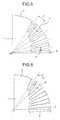
- FIGs. 1 to 7 show a rotor of a rotting eclectic machine according to the first embodiment of the present invention, in which the illustration of a stator is omitted.
- reference numeral “1” denotes a rotor core (1/4 part) of the rotating electric machine.
- Reference numeral “2” denotes a magnetic pole portion
- numeral 3 denotes a non-polar portion
- numeral "4" denotes a rotor slot formed in the non-polar portion 3
- numeral "5" denotes a rotor tooth portion
- numeral "6" denotes an interpolar portion.
- the rotor core 1 of the rotating electric machine has a plurality of rotor slots 4 for housing not shown rotor coils, which are formed by cutting the rotor core 1 from the outer diameter side thereof to the inner diameter side.
- the cross-sectional areas S1, S2, S3 and S4 of the plurality of rotor slots 4 other than rotor slots 4a formed at the position nearest to the magnetic pole portions 2 are stepwise increased (S1 ⁇ S2 ⁇ S3 ⁇ S4) in the direction from the magnetic pole portions 2 toward the interpolar portions 6.
- the widths L of the rotor slots 4 are gradually increased in the direction from the magnetic pole portions 2 toward the interpolar portions 6 in a range within which the stress of the rotor tooth portions 5 is maintained with the depths d of the rotor slots 4 set to a constant value. In this case, the increase need not be stepwise.
- the depths d of the rotor slots 4 may gradually be increased in the direction from the magnetic pole portions 2 toward the interpolar portions 6 in a range within which the stress of the rotor tooth portions 5 is maintained with the widths L of the rotor slots 4 set to a constant value.
- a configuration may be adopted in which, with the widths L of the rotor slots 4 set to a constant value, the slot interval angles ⁇ (interval angles between the slots) between adjacent slots are stepwise increased in the direction from the magnet pole portions 2 toward the interpolar portions 6 such that ⁇ 1 ⁇ ⁇ 2 ⁇ ⁇ 3 ⁇ ⁇ 4 is established and, at the same time, the depths d of the rotor slots 4 are stepwise increased in the direction from the magnetic pole portions 2 toward the interpolar portions 6 in a range within which the stress of the rotor tooth portions 5 is maintained.
- the slot interval angles ⁇ interval angles between the slots
- a configuration may be adopted in which the depths d of the rotor slots 4 are stepwise increased in the direction from the magnetic pole portions 2 toward the interpolar portions 6 and, at the same time, the widths L of the rotor slots 4 are stepwise increased in the direction from the magnetic pole portions 2 toward the interpolar portions 6 such that L 1 ⁇ L 2 ⁇ L 3 ⁇ L 4 is established in a range within which the stress of the rotor tooth portions 5 is maintained.
- the depths d of the rotor slots 4 are stepwise increased in the direction from the magnetic pole portions 2 toward the interpolar portions 6 and, at the same time, the widths L of the rotor slots 4 are stepwise increased in the direction from the magnetic pole portions 2 toward the interpolar portions 6 such that L 1 ⁇ L 2 ⁇ L 3 ⁇ L 4 is established in a range within which the stress of the rotor tooth portions 5 is maintained.
- a configuration may be adopted in which the slot interval angles ⁇ of the rotor slots 4 are stepwise increased in the direction from the magnetic pole portions 2 toward the interpolar portions 6 and, at the same time, the widths L of the rotor slots 4 are stepwise increased in the direction from the magnetic pole portions 2 toward the interpolar portions 6 in a range within which the stress of the rotor tooth portions 5 is maintained.
- a configuration may be adopted in which the slot interval angles ⁇ of the rotor slots 4 are stepwise increased in the direction from the magnetic pole portions 2 toward the interpolar portions 6 and, at the same time, the widths L and depths d of the rotor slots 4 are controlled in a range within which the stress of the rotor tooth portions 5 is maintained so as to increase the total cross-sectional area S of the rotor slots 4.
- the width L of the rotor slots 4 may be tapered toward the rotor inner diameter side.
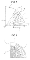
- the cross-sectional areas S1, S2, S3, and S4 of the plurality of rotor slots 4 formed in the rotor core 1 other than the rotor slots 4a formed at the position nearest to the magnetic pole portions 2 are stepwise increased (S1 ⁇ S2 ⁇ S3 ⁇ S4) in the direction from the magnetic pole portions 2 toward the interpolar portions 6. This allows the absolute amount of windings of the field coils housed in the rotor slots 4 to be increased, resulting in an increase in the cross-sectional area to which the field current is applied.
- the heat generation density of the field coil to be energized is reduced, which is advantageous in terms of coil cooling as compared to another rotor configuration having the same outer diameter.
- draft loss can be reduced by a reduction in the amount of cooling air, thereby contributing to an improvement in the generator efficiency.
- stepwise increasing the cross-sectional areas of the rotor slots 4 in the direction from the magnetic pole portions 2 toward the interpolar portions 6, it is possible to suppress an increase in the temperature of the rotor coils 7 arranged on the interpolar portion sides where the length of the field coils are large, suppressing the amount of heat expansion of th.e field coils. As a result, it is possible to provide a safer generator.
- Distribution of the field flux ⁇ according to the present embodiment is shown in FIG. 8 .
- the influence of the field flux is small, so that it is possible to effectively utilize the part of the rotor core that is outside the narrowest width dimension G portion.
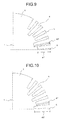
- FIG. 9 shows the shape of the rotor core 1 of a rotating electric machine according to the second embodiment of the present invention.
- the rotor core 1 according to the present embodiment has a plurality of rotor slots 4 for housing rotor coils, which are formed by cutting the rotor core 1 from the outer diameter side thereof to the inner diameter side, the depth d of the rotor slots 4 being varied (at two values of d1 and d2).
- the width of the rotor tooth portions 5 are designed such that the rotor tooth portions 5 have sufficient mechanical strength against the centrifugal force to be applied to the field coils.
- the width L1 of the rotor slots 4 having the smaller depth (d1) is made larger than the width L2 of the rotor slots 4 having the larger depth (d2).
- the width L of the rotor slots 4 may be tapered toward the rotor inner diameter side.
- the heat generation density of the field coils to be energized is reduced, which is advantageous in terms of coil cooling as compared to another rotor configuration having the same outer diameter.
- draft loss can be reduced by a reduction in the amount of cooling air, thereby contributing to an improvement in the generator efficiency.
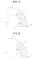
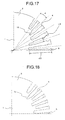
- a third embodiment of the present invention will be described below with reference to FIGs. 13 to 18 .
- FIG. 13 shows the shape of the rotor core 1 of a rotating electric machine according to a third embodiment of the present invention.
- the rotor core 1 according to the present embodiment has a plurality of rotor slots 4 for housing rotor coils, which are formed by cutting the rotor core 1 from the outer diameter side thereof to the inner diameter side, and cooling gas ducts 13 for supplying cooling gas to the rotor coils are formed at the inner diameter side of each of the rotor slots 4.
- the cross-sectional areas of the cooling gas ducts 13 are stepwise increased in the direction from the magnetic pole portions 2 toward the non-polar portions 6.
- the width of the rotor tooth portions 5 is designed such that the rotor tooth portions 5 have sufficient mechanical strength against the centrifugal force to be applied to the field coils.
- the slot widths L3 of the cooling gas ducts 13 may be stepwise increased in the direction from the magnetic pole portions 2 toward the interpolar portions 6.
- the width of the cooling gas ducts 13 may be tapered toward the rotor inner diameter side.
- the reduction of draft loss contributes to an improvement in the generator efficiency.
- cooling gas ducts 13 at the inner diameter side, it is possible to increase self-fanning effect produced by the rotation, thereby enhancing cooling performance. As a result, it is possible to achieve an increase in the generator output power or a reduction in the size of the generator.
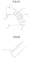
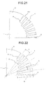
- a fourth embodiment of the present invention will be described below with reference to FIGs. 19 to 23 .
- FIG. 19 shows the shape of the rotor core 1 of a rotating electric machine according to a fourth embodiment of the present invention.
- the rotor core 1 according to the present embodiment has a plurality of rotor slots 4 for housing rotor coils, which are formed by cutting the rotor core 1 from the outer diameter side thereof to the inner diameter side, and a cooling gas ducts 14 for supplying cooling gas to the rotor coils are formed at the side surface of each of the rotor slots 4 (rotor tooth portions 5).
- the shape of the cooling gas ducts 14 is not limited to those shown in FIG. 19 but the cooling gas ducts 14 may have any shape, such as trapezoid shape as shown in FIG. 20 , as long as the rotor coils housed are not displaced from a proper position during generator operation.
- the width of the rotor tooth portions 5 is designed such that the rotor tooth portions 5 have sufficient mechanical strength against the centrifugal force to be applied to the field coils.
- the cooling gas ducts 14 may be most effectively formed at the side surface of each of the slots 4a nearest to the magnetic pole portions 2 as shown in FIG. 21 .
- cooling gas ducts 13 and 14 are simultaneously formed in the configuration combined with the features of the first and/or second embodiments.
- cooling gas ducts 14 for supplying cooling gas to the rotor coils 7 at the side surface of each of the rotor slots 4 it is possible to increase the allowable range of the slot depth d of the rotor slots 4. Further, it is possible to ensure a larger total cross-sectional area of the rotor slots 4 without influencing the width G of the narrowest portions of the magnetic pole portions 2.
- cooling gas ducts 14 for supplying cooling gas to the rotor coils 7 at the side surface of each of the rotor slots 4 it is possible to increase the slot depth d of the rotor slots 4 formed in the rotor core 1 to thereby increase the total cross-sectional area S of the rotor slots 4.
- This increases the cross-sectional area to which the field current is applied, so that the field current density can be reduced in the rotor slots in which the cross-sectional area to which the field current is applied is increased.
- the heat generation density of the field coil to be energized is reduced, which is advantageous in terms of coil cooling as compared to another rotor configuration having the same outer diameter.
- draft loss can be reduced by a reduction in the amount of cooling air, thereby contributing to an improvement in the generator efficiency.
Landscapes
- Engineering & Computer Science (AREA)
- Power Engineering (AREA)
- Iron Core Of Rotating Electric Machines (AREA)
Applications Claiming Priority (1)
| Application Number | Priority Date | Filing Date | Title |
|---|---|---|---|
| PCT/JP2007/000421 WO2008136044A1 (ja) | 2007-04-18 | 2007-04-18 | 回転電機 |
Publications (2)
| Publication Number | Publication Date |
|---|---|
| EP2139092A1 true EP2139092A1 (de) | 2009-12-30 |
| EP2139092A4 EP2139092A4 (de) | 2013-05-01 |
Family
ID=39943169
Family Applications (1)
| Application Number | Title | Priority Date | Filing Date |
|---|---|---|---|
| EP07737078.1A Withdrawn EP2139092A4 (de) | 2007-04-18 | 2007-04-18 | Elektrische drehmaschine |
Country Status (4)
| Country | Link |
|---|---|
| US (1) | US8138653B2 (de) |
| EP (1) | EP2139092A4 (de) |
| CN (1) | CN101647178B (de) |
| WO (1) | WO2008136044A1 (de) |
Cited By (1)
| Publication number | Priority date | Publication date | Assignee | Title |
|---|---|---|---|---|
| US20220302812A1 (en) * | 2021-03-22 | 2022-09-22 | Hunan University Of Science And Technology | Optimization design method for noise reduction of ac traction motor |
Families Citing this family (5)
| Publication number | Priority date | Publication date | Assignee | Title |
|---|---|---|---|---|
| JP5527050B2 (ja) * | 2010-06-30 | 2014-06-18 | 株式会社デンソー | 回転電機の固定子及びその製造方法 |
| KR101531525B1 (ko) * | 2012-10-31 | 2015-06-25 | 엘지전자 주식회사 | 전기자동차용 구동모터 및 이의 제어방법 |
| US20140239766A1 (en) * | 2013-02-28 | 2014-08-28 | General Electric Company | Generator lead system |
| CN107124049B (zh) * | 2017-06-29 | 2023-04-25 | 广东美芝制冷设备有限公司 | 定子、电机及空调压缩机 |
| KR102323758B1 (ko) * | 2018-09-18 | 2021-11-08 | 재단법인대구경북과학기술원 | 스테이터 및 이를 포함하는 모터 어셈블리 |
Family Cites Families (27)
| Publication number | Priority date | Publication date | Assignee | Title |
|---|---|---|---|---|
| US1723912A (en) * | 1928-02-15 | 1929-08-06 | Gen Electric | Dynamo-electric machine |
| US3600618A (en) * | 1969-10-27 | 1971-08-17 | Gen Motors Corp | Wound rotor alternator coil slot construction |
| GB1352320A (en) * | 1970-04-02 | 1974-05-08 | Reyrolle Parsons Ltd | Dynamo-electric machines |
| JPS5291104A (en) | 1976-01-27 | 1977-08-01 | Gantsu Biramotsusagi Miyubeku | Highhoutput highhspeed electric synchronous machine with cylindrical rotor |
| US4390806A (en) * | 1980-09-02 | 1983-06-28 | General Electric Company | Dynamoelectric machine rotors with mechanical separators |
| JPS5798151U (de) * | 1980-12-04 | 1982-06-16 | ||
| JPS5798151A (en) | 1980-12-09 | 1982-06-18 | Matsushita Electric Ind Co Ltd | Magnetic recorder and reproducer |
| JPS599741U (ja) * | 1982-07-07 | 1984-01-21 | 三菱電機株式会社 | 回転電機の回転子鉄心 |
| JPS599741A (ja) | 1982-07-09 | 1984-01-19 | Mitsubishi Electric Corp | インタ−フエ−ス方式 |
| JPS59103584A (ja) | 1982-11-30 | 1984-06-15 | Ichirou Mokudai | 永久磁石を利用した磁気発動装置 |
| JPS59103582A (ja) | 1982-12-04 | 1984-06-15 | Fuji Electric Co Ltd | 複数個のパルストランスの駆動方法 |
| JPS59103585A (ja) | 1982-12-06 | 1984-06-15 | Mitsubishi Electric Corp | 電動機の制御装置 |
| JPS59103585U (ja) * | 1982-12-27 | 1984-07-12 | 三菱電機株式会社 | 超電導回転電機の回転子 |
| JPS59103584U (ja) * | 1982-12-27 | 1984-07-12 | 三菱電機株式会社 | 超電導回転電機の回転子 |
| JPS59103582U (ja) * | 1982-12-27 | 1984-07-12 | 三菱電機株式会社 | 超電導回転電機の回転子 |
| JPH023172A (ja) | 1988-06-10 | 1990-01-08 | Hitachi Ltd | 半導体記憶装置 |
| JPH023172U (de) * | 1988-06-15 | 1990-01-10 | ||
| US4900964A (en) * | 1989-01-11 | 1990-02-13 | Westinghouse Electric Corp. | Pole face slot filler |
| US5030871A (en) * | 1990-05-11 | 1991-07-09 | General Electric Company | Reducing harmonic losses in dynamoelectric machine rotors |
| JPH0984312A (ja) | 1995-09-19 | 1997-03-28 | Hitachi Ltd | 回転電機 |
| JPH09154246A (ja) * | 1995-11-29 | 1997-06-10 | Hitachi Ltd | 回転電機の回転子 |
| JPH1189132A (ja) | 1997-09-04 | 1999-03-30 | Hitachi Ltd | 回転電機の円筒形回転子 |
| JPH11206045A (ja) | 1998-01-05 | 1999-07-30 | Hitachi Ltd | 回転電機 |
| JP3521261B2 (ja) * | 1998-04-13 | 2004-04-19 | 株式会社日立製作所 | 回転電機の回転子 |
| DE10302892A1 (de) * | 2003-01-17 | 2004-08-05 | Bühler Motor GmbH | Blechschnitt |
| US7786645B2 (en) * | 2006-09-07 | 2010-08-31 | American Superconductor Corporation | Superconducting machine stator |
| JP2008295264A (ja) * | 2007-05-28 | 2008-12-04 | Toshiba Corp | 回転電機の回転子 |
-
2007
- 2007-04-18 WO PCT/JP2007/000421 patent/WO2008136044A1/ja not_active Ceased
- 2007-04-18 CN CN2007800525671A patent/CN101647178B/zh not_active Expired - Fee Related
- 2007-04-18 EP EP07737078.1A patent/EP2139092A4/de not_active Withdrawn
- 2007-04-18 US US12/530,531 patent/US8138653B2/en active Active
Cited By (2)
| Publication number | Priority date | Publication date | Assignee | Title |
|---|---|---|---|---|
| US20220302812A1 (en) * | 2021-03-22 | 2022-09-22 | Hunan University Of Science And Technology | Optimization design method for noise reduction of ac traction motor |
| US11824411B2 (en) * | 2021-03-22 | 2023-11-21 | Hunan University Of Science And Technology | Optimization design method for noise reduction of AC traction motor |
Also Published As
| Publication number | Publication date |
|---|---|
| CN101647178B (zh) | 2012-10-10 |
| US20100084942A1 (en) | 2010-04-08 |
| CN101647178A (zh) | 2010-02-10 |
| EP2139092A4 (de) | 2013-05-01 |
| WO2008136044A1 (ja) | 2008-11-13 |
| US8138653B2 (en) | 2012-03-20 |
Similar Documents
| Publication | Publication Date | Title |
|---|---|---|
| EP1990895B1 (de) | Belastungsverteilende Permamentmagnet-Rotorgeometrie für elektrische Maschinen | |
| US7893575B2 (en) | Rotor with field coils in optimized flux space slots | |
| JP5202455B2 (ja) | 永久磁石埋め込み型回転子及び掃除機 | |
| US8138653B2 (en) | Rotating electric machine | |
| CN110462982A (zh) | 同步磁阻机器 | |
| CN110663158B (zh) | 用于交流电机的双磁相材料环 | |
| CN102132472B (zh) | 电机 | |
| JP2007300787A (ja) | 発電機・電動機用回転子 | |
| KR101019665B1 (ko) | 각선용 고정자 코어 | |
| RU2538835C1 (ru) | Радиальный магнитный подшипник для магнитной опоры ротора | |
| JP2017093195A (ja) | 回転電機 | |
| KR20210137550A (ko) | 영구 자석 보조 동기 릴럭턴스 기계 | |
| EP2372106B1 (de) | Turbogenerator | |
| JP4670661B2 (ja) | 車両用交流発電機 | |
| US9935512B2 (en) | Permanent magnet rotating electrical machine | |
| JP2007330018A (ja) | タンデム型交流発電機の回転子 | |
| US6211596B1 (en) | Claw-pole machine | |
| JP2007116801A (ja) | 回転電機 | |
| EP4299951A1 (de) | Magnetische zahnraddrehmaschine, stromerzeugungssystem und magnetpolstückrotor | |
| EP0971475A1 (de) | Stator eines Einphasenelektromotors mit vier parallelen Polen | |
| US6329733B1 (en) | Radial magnetic bearing | |
| JP5129034B2 (ja) | 交流励磁回転電機 | |
| CN102447321A (zh) | 电机 | |
| US20060043814A1 (en) | Trapezoidal field pole shape in salient machines | |
| JPH10164787A (ja) | 回転電機の突極形回転子 |
Legal Events
| Date | Code | Title | Description |
|---|---|---|---|
| PUAI | Public reference made under article 153(3) epc to a published international application that has entered the european phase |
Free format text: ORIGINAL CODE: 0009012 |
|
| 17P | Request for examination filed |
Effective date: 20090909 |
|
| AK | Designated contracting states |
Kind code of ref document: A1 Designated state(s): AT BE BG CH CY CZ DE DK EE ES FI FR GB GR HU IE IS IT LI LT LU LV MC MT NL PL PT RO SE SI SK TR |
|
| DAX | Request for extension of the european patent (deleted) | ||
| A4 | Supplementary search report drawn up and despatched |
Effective date: 20130404 |
|
| RIC1 | Information provided on ipc code assigned before grant |
Ipc: H02K 1/32 20060101ALI20130327BHEP Ipc: H02K 1/26 20060101AFI20130327BHEP |
|
| 17Q | First examination report despatched |
Effective date: 20160616 |
|
| STAA | Information on the status of an ep patent application or granted ep patent |
Free format text: STATUS: THE APPLICATION IS DEEMED TO BE WITHDRAWN |
|
| 18D | Application deemed to be withdrawn |
Effective date: 20161027 |