US4900964A - Pole face slot filler - Google Patents
Pole face slot filler Download PDFInfo
- Publication number
- US4900964A US4900964A US07/295,699 US29569989A US4900964A US 4900964 A US4900964 A US 4900964A US 29569989 A US29569989 A US 29569989A US 4900964 A US4900964 A US 4900964A
- Authority
- US
- United States
- Prior art keywords
- filler
- pole face
- rotor
- face slot
- base portion
- Prior art date
- Legal status (The legal status is an assumption and is not a legal conclusion. Google has not performed a legal analysis and makes no representation as to the accuracy of the status listed.)
- Expired - Fee Related
Links
Images
Classifications
-
- H—ELECTRICITY
- H02—GENERATION; CONVERSION OR DISTRIBUTION OF ELECTRIC POWER
- H02K—DYNAMO-ELECTRIC MACHINES
- H02K1/00—Details of the magnetic circuit
- H02K1/06—Details of the magnetic circuit characterised by the shape, form or construction
- H02K1/22—Rotating parts of the magnetic circuit
- H02K1/26—Rotor cores with slots for windings
Definitions
- the present invention relates to pole face slot fillers which are installed in slots formed in the pole faces of generator rotors.
- the outer surface of a generator rotor is generally divided, in the circumferential direction, between winding regions and pole regions.
- Each winding region is provided with a plurality of axially extending slots, separated by teeth, the slots containing conductors which are connected at their ends to form the rotor winding.
- the effective density of the rotor is greater in the pole regions than in the winding regions, causing the rotor to have different stiffness, i.e., different moments of inertia about various axes perpendicular to the axis of rotation, which leads to double frequency vibrations.
- the rotor will tend to be deformed into an elliptical shape due to centrifugal forces.
- pole regions of such a rotor with slots generally similar to those provided in the winding regions.
- pole region slots must be provided with slot fillers of a material suitable to provide the necessary magnetic flux paths in each pole region.
- the pole face slot fillers are held in place by wedges, which can be similar to the wedges used to retain the conductors installed in the winding region slots.
- pole face slot fillers increase the effective density of the pole regions, causing the rotor to have different stiffness, or different moments of inertia about various axes
- these fillers are usually given a relatively short axial length so as not to affect stiffness and each pole face slot is usually provided with a plurality of such fillers, spaced apart in the axial direction of the rotor, and each pole face slot filler is generally provided with a cutout which can additionally serve as a vent passage for a radially ventilated rotor.
- pole face slot fillers have relatively short lengths, they have a tendency to rattle, thereby producing undesired vibrations.
- the pole face slot fillers tend to migrate axially when the generator is started up or stopped.
- a more specific object of the invention is to provide pole face slot fillers which, while remaining structurally simple, will show no tendency to rattle or migrate axially.
- a pole face slot filler for insertion into a pole face slot formed in a pole region of a generator rotor, the filler having a U-shaped cross section and being composed of a base portion and two leg portions extending from the base portion and forming the legs of the U-shaped cross section, wherein the filler is configured and dimensioned to achieve a press fit in the pole face slot.
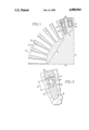
- FIG. 1 is a cross-sectional view of a portion of a generator rotor provided with pole face slots and pole face slot fillers which can be constructed according to the present invention.
- FIG. 2 is a cross-sectional view of one preferred embodiment of a pole face slot filler according to the invention.
- FIG. 1 shows one-fourth of a generator rotor, bounded by a pole axis 12 and a quadrature axis 14, containing one-half of a winding region 16 and onehalf of a pole region 18.
- Region 16 contains conventional winding slots 20 separated by teeth 22. Each tooth 22 is formed with recesses 24 for holding wedges in the outer ends of slots 20.
- Pole region 18 is provided with longitudinal, or axial, pole face slots for the purpose of equalizing the moments of inertia about axes 12 and 14.
- pole face slot fillers 26 and 28 are introduced into the pole face slots to provide the necessary magnetic flux paths. Fillers 26 and 28 are held in place by wedges 30, typically made of copper. Wedges 30 can be identical to those that will be installed at the rotor circumference ends of winding slots 20.
- pole regions usually have a greater density than the winding regions, rotors tend to be deformed into an elliptical form during their operation. Reductions can be achieved by providing each pole face slot filler 26, 28 with a cutout, or recess, 34. Recesses 34 additionally serve as vent passages for a radially ventilated rotor. Wedges 30 which serve to retain fillers 26 and 28 in place can also provide electrical damping.
- pole face slots and their associated fillers 26, 28 are located and dimensioned to equalize the moments of inertia about pole axis 12 and quadrature axis 14.
- the dimensions of recesses 34 are selected on the basis of the desired reduction in pole centrifugal force and required ventilation cross section.
- Fillers 26 and 28 generally must be of short axial lengths , such lengths should be shorter than the axial lengths of the rotor, in order to not defeat the moment of inertia equalization created by the pole slots. Accordingly, during generator operation, known fillers tend to rattle and to migrate axially during starting and stopping of the rotor. These movements are undesirable.
- each pole face slot filler 26, 28 which has a U-shaped cross section, so that each filler is dimensioned at its upper edge to achieve a press fit with the associated pole face slot.
- FIG. 2 An exemplary embodiment is shown in FIG. 2 and corresponds to filler 26 of FIG. 1.
- the dimensions for filler 26 are chosen according to the considerations described above.
- Filler 26 is composed generally of a base portion 36 and two leg portions 38 which extend from base portion 36 in a direction corresponding essentially to a radial direction of the rotor when filler 26 is installed in a pole face slot.
- filler 26 is provided at its upper edge with outwardly protruding lips, or bosses, 40 dimensioned to create a press fit with the side walls of the associated pole face slot.
- a press fit is achieved by giving filler 26 a horizontal dimension, in the plane of FIG. 2, in the region of lips 40 which, before insertion in a pole face slot, exceeds the distance between the walls of the pole face slot by a small amount.
- this dimension is selected so that when filler 26 is installed in a pole face slot, the compression force acting on lips 40 will produce a frictional force between lips 40 and the pole face slot walls, in the radial direction of the rotor, which is at least 10 times the weight of filler 26.
- a frictional force having this order of magnitude will prevent any rattling or axial migration of filler 26 without interfering with easy installation of filler 26 in the pole face slot.
- base portion 36 will be dimensioned to achieve a snug fit with a small clearance with its associated portion of the pole face slot.
- filler 26 could have an axial length of the order of 12.7 cm (5"), a cutout height 42 of 3.8 cm (1.5"), cutout width 44 of 1.59 cm (0.625"), an external width 46, in the region of leg portions 38, of 2.855 cm (1.124"), and an external width, at the level of lips 40, of 2.88 cm (1.134”), this dimension being when filler 26 has not yet been inserted in the pole face slot and is therefore undeformed.
- the pole face slot is formed to have a width which is approximately 0.1 mm (0.004") less than the undeformed external width of filler 26 at the level of lips 40.
- the press fit established between filler 26 and the walls of its associated pole face slot will generate, in the radial direction, a frictional force of the order of 5.37 Kg/cm (30 lb/in) along each slot wall, for a total frictional force of 10.75 Kg/cm (60 lb/in), the length dimensions being parallel to the axis of the rotor.
- the base portion 36 of filler 26 can be given a height and cross-sectional configuration corresponding to the height and cross-sectional configuration of the associated pole face slot, which depends on the extent to which the weight of pole region 18 is to be reduced. These dimensions can be selected such that, if filler 26 is made of steel, and the dimensions described above are selected, filler 26 can be given a weight of 0.125 Kg/cm (0.7 lb/in). The weight and friction forces identified above are relative to the axial dimension of filler 26.
- Base portion 36 and the corresponding part of the pole face slot, can be tapered, as shown in FIG. 2, although such configuration may make it more difficult to machine the sides of the slot and base portion 36, and to control the required fits.
- the entire filler, including leg portions 38, can be tapered.
- Filler 28 differs from filler 26 only with respect to the size of base portion 36. With regard to the base portion, the dimensions and configurations for each filler are selected so as to not interfere with other components on the rotor.
- the number of pole face slots and fillers provided in each pole region is determined according to principles known in the art on the basis of the extent to which the weight of a pole region is to be reduced and the amount of filler material needed to establish the required magnetic flux paths.
- each filler 26, 28 is given a radial dimension such that when the filler is fully seated in its associated slot, a radial gap of the order of 0.76 mm (0.030 in) exists between the filler and the associated wedge 30.
- This will facilitate installation of wedge 30, which is generally installed by sliding it axially into the grooves provided therefor in the slot walls. Then, when the assembled rotor is subjected to an overspeed test, fillers 26, 28 will move radially outwardly to press against wedges 30, thereby preventing wedges 30 from rattling or experiencing any axial migration.
Abstract
Description
Claims (8)
Priority Applications (1)
| Application Number | Priority Date | Filing Date | Title |
|---|---|---|---|
| US07/295,699 US4900964A (en) | 1989-01-11 | 1989-01-11 | Pole face slot filler |
Applications Claiming Priority (1)
| Application Number | Priority Date | Filing Date | Title |
|---|---|---|---|
| US07/295,699 US4900964A (en) | 1989-01-11 | 1989-01-11 | Pole face slot filler |
Publications (1)
| Publication Number | Publication Date |
|---|---|
| US4900964A true US4900964A (en) | 1990-02-13 |
Family
ID=23138856
Family Applications (1)
| Application Number | Title | Priority Date | Filing Date |
|---|---|---|---|
| US07/295,699 Expired - Fee Related US4900964A (en) | 1989-01-11 | 1989-01-11 | Pole face slot filler |
Country Status (1)
| Country | Link |
|---|---|
| US (1) | US4900964A (en) |
Cited By (11)
| Publication number | Priority date | Publication date | Assignee | Title |
|---|---|---|---|---|
| US5030871A (en) * | 1990-05-11 | 1991-07-09 | General Electric Company | Reducing harmonic losses in dynamoelectric machine rotors |
| US5072146A (en) * | 1989-08-04 | 1991-12-10 | The Glacier Metal Company Limited | Magnetic bearings coil heat removal |
| US5469009A (en) * | 1993-06-18 | 1995-11-21 | Hitachi, Ltd. | Turbine generator |
| US20030155833A1 (en) * | 2002-02-21 | 2003-08-21 | Hitachi, Ltd. | Rotor in a rotary electric machine |
| US6833640B2 (en) * | 2000-12-07 | 2004-12-21 | Siemens Westinghouse Power Corporation | Method and apparatus to tune rotor's torsional natural frequency by geometry of rotor winding slot |
| US20050212379A1 (en) * | 2004-03-23 | 2005-09-29 | General Electric Company | Module winding system for electrical machines and methods of electrical connection |
| US20080296989A1 (en) * | 2007-05-28 | 2008-12-04 | Kabushiki Kaisha Toshiba | Rotor of rotary electric machine, and rotary electronic machine |
| US20100084942A1 (en) * | 2007-04-18 | 2010-04-08 | Kabushiki Kaisha Toshiba | Rotating electric machine |
| US20110050028A1 (en) * | 2009-08-27 | 2011-03-03 | Bernd Ponick | Electrical machine and process for manufacturing an electrical machine |
| US9509183B2 (en) | 2013-07-19 | 2016-11-29 | General Electric Company | Rotor with non-cylindrical surface for dynamoelectric machine |
| PL428574A1 (en) * | 2019-01-14 | 2019-08-12 | Instytut Napędów I Maszyn Elektrycznych Komel | Slotted insulation of the electric machine winding |
Citations (8)
| Publication number | Priority date | Publication date | Assignee | Title |
|---|---|---|---|---|
| DE536738C (en) * | 1930-07-10 | 1931-10-26 | Albert Hoeing | Rail fastening on rib support plates by means of a clamping plate and wedge screw arrangement accommodated in an opening in the ribs |
| DE615090C (en) * | 1929-11-23 | 1935-06-27 | Franklin Punga | Synchronous power plant with synchronous active power generators and synchronous reactive power generators with damper winding |
| US2565530A (en) * | 1950-11-02 | 1951-08-28 | Vincent K Smith | Dynamoelectric machine and method of making same |
| DE1052544B (en) * | 1957-08-21 | 1959-03-12 | Siemens Ag | Cooling of the short-circuit rings of the damper winding for turbo generators |
| US3745394A (en) * | 1967-07-17 | 1973-07-10 | Gen Electric | Electrical insulators for slotted magnetic cores |
| US3943392A (en) * | 1974-11-27 | 1976-03-09 | Allis-Chalmers Corporation | Combination slot liner and retainer for dynamoelectric machine conductor bars |
| US4560896A (en) * | 1984-10-01 | 1985-12-24 | General Electric Company | Composite slot insulation for dynamoelectric machine |
| US4633116A (en) * | 1985-10-31 | 1986-12-30 | General Electric Company | Sub-slot cover for dynamoelectric machine |
-
1989
- 1989-01-11 US US07/295,699 patent/US4900964A/en not_active Expired - Fee Related
Patent Citations (8)
| Publication number | Priority date | Publication date | Assignee | Title |
|---|---|---|---|---|
| DE615090C (en) * | 1929-11-23 | 1935-06-27 | Franklin Punga | Synchronous power plant with synchronous active power generators and synchronous reactive power generators with damper winding |
| DE536738C (en) * | 1930-07-10 | 1931-10-26 | Albert Hoeing | Rail fastening on rib support plates by means of a clamping plate and wedge screw arrangement accommodated in an opening in the ribs |
| US2565530A (en) * | 1950-11-02 | 1951-08-28 | Vincent K Smith | Dynamoelectric machine and method of making same |
| DE1052544B (en) * | 1957-08-21 | 1959-03-12 | Siemens Ag | Cooling of the short-circuit rings of the damper winding for turbo generators |
| US3745394A (en) * | 1967-07-17 | 1973-07-10 | Gen Electric | Electrical insulators for slotted magnetic cores |
| US3943392A (en) * | 1974-11-27 | 1976-03-09 | Allis-Chalmers Corporation | Combination slot liner and retainer for dynamoelectric machine conductor bars |
| US4560896A (en) * | 1984-10-01 | 1985-12-24 | General Electric Company | Composite slot insulation for dynamoelectric machine |
| US4633116A (en) * | 1985-10-31 | 1986-12-30 | General Electric Company | Sub-slot cover for dynamoelectric machine |
Cited By (19)
| Publication number | Priority date | Publication date | Assignee | Title |
|---|---|---|---|---|
| US5072146A (en) * | 1989-08-04 | 1991-12-10 | The Glacier Metal Company Limited | Magnetic bearings coil heat removal |
| US5030871A (en) * | 1990-05-11 | 1991-07-09 | General Electric Company | Reducing harmonic losses in dynamoelectric machine rotors |
| US5469009A (en) * | 1993-06-18 | 1995-11-21 | Hitachi, Ltd. | Turbine generator |
| US6833640B2 (en) * | 2000-12-07 | 2004-12-21 | Siemens Westinghouse Power Corporation | Method and apparatus to tune rotor's torsional natural frequency by geometry of rotor winding slot |
| US20030155833A1 (en) * | 2002-02-21 | 2003-08-21 | Hitachi, Ltd. | Rotor in a rotary electric machine |
| US6774522B2 (en) * | 2002-02-21 | 2004-08-10 | Hitachi, Ltd. | Rotor with slot wedges having different dimension to reduce stress |
| US20050212379A1 (en) * | 2004-03-23 | 2005-09-29 | General Electric Company | Module winding system for electrical machines and methods of electrical connection |
| US6989621B2 (en) * | 2004-03-23 | 2006-01-24 | General Electric Company | Module winding system for electrical machines and methods of electrical connection |
| EP1580867A3 (en) * | 2004-03-23 | 2011-01-05 | General Electric Company | Module winding system for electrical machines and methods of electrical connection |
| CN1674409B (en) * | 2004-03-23 | 2011-01-26 | 通用电气公司 | Module winding system and electric connecting method for electric machine |
| KR101126873B1 (en) * | 2004-03-23 | 2012-03-26 | 제너럴 일렉트릭 캄파니 | Module winding system for electrical machines and methods of electrical connection |
| US8138653B2 (en) * | 2007-04-18 | 2012-03-20 | Kabushiki Kaisha Toshiba | Rotating electric machine |
| US20100084942A1 (en) * | 2007-04-18 | 2010-04-08 | Kabushiki Kaisha Toshiba | Rotating electric machine |
| CN101647178B (en) * | 2007-04-18 | 2012-10-10 | 株式会社东芝 | Rotating electric machine |
| US20080296989A1 (en) * | 2007-05-28 | 2008-12-04 | Kabushiki Kaisha Toshiba | Rotor of rotary electric machine, and rotary electronic machine |
| US7893575B2 (en) * | 2007-05-28 | 2011-02-22 | Kabushiki Kaisha Toshiba | Rotor with field coils in optimized flux space slots |
| US20110050028A1 (en) * | 2009-08-27 | 2011-03-03 | Bernd Ponick | Electrical machine and process for manufacturing an electrical machine |
| US9509183B2 (en) | 2013-07-19 | 2016-11-29 | General Electric Company | Rotor with non-cylindrical surface for dynamoelectric machine |
| PL428574A1 (en) * | 2019-01-14 | 2019-08-12 | Instytut Napędów I Maszyn Elektrycznych Komel | Slotted insulation of the electric machine winding |
Similar Documents
| Publication | Publication Date | Title |
|---|---|---|
| US4900964A (en) | Pole face slot filler | |
| US3943392A (en) | Combination slot liner and retainer for dynamoelectric machine conductor bars | |
| CA1177869A (en) | Dynamoelectric machine stator wedges and method | |
| US5886443A (en) | Spark suppression of induction type rotors of dynamoelectric machines | |
| US5739615A (en) | Rotor for reluctance machine | |
| US3832583A (en) | Squirrel cage motor with improved rotor bar securing arrangement | |
| US6121708A (en) | Slot sealing arrangement | |
| US3940647A (en) | Slot closure for dynamoelectric machine | |
| US3775626A (en) | External-rotor reluctance motor | |
| US3463949A (en) | End frame attachment for dynamoelectric machine | |
| US4082974A (en) | Gap winding type dynamo-electric machine | |
| US4015156A (en) | Dynamoelectric machine locking wedge for coil retention | |
| JP3653838B2 (en) | Permanent magnet type synchronous rotating machine rotor | |
| US4184091A (en) | Oppositely directed slotting wedges for retaining the winding of an electric machine stator | |
| US2087406A (en) | Dynamo-electric machine | |
| US2232773A (en) | Armature construction | |
| JP3521261B2 (en) | Rotating electric machine rotor | |
| ES2006239A6 (en) | Dynamoelectric machine coil slot wedge mounting arrangement | |
| US3196304A (en) | Protective means for insulation | |
| US6777848B1 (en) | Laminated stator body for an electrical machine | |
| WO1998043340A1 (en) | Method and apparatus for profiling magnetic flux | |
| US3651357A (en) | Dynamo-electric machines | |
| KR102210361B1 (en) | Rotator core and induction motor having the same | |
| JP2000037053A (en) | Permanent magnet type motor | |
| EP1009090A1 (en) | Spark suppresion of induction type rotors |
Legal Events
| Date | Code | Title | Description |
|---|---|---|---|
| AS | Assignment |
Owner name: WESTINGHOUSE ELECTRIC CORPORATION, A CORP. OF PA, Free format text: ASSIGNMENT OF ASSIGNORS INTEREST.;ASSIGNORS:YING, SUI-CHUN;HAGAMAN, ROBERT T.;REEL/FRAME:005019/0032 Effective date: 19881227 |
|
| FPAY | Fee payment |
Year of fee payment: 4 |
|
| FPAY | Fee payment |
Year of fee payment: 8 |
|
| AS | Assignment |
Owner name: SIEMENS WESTINGHOUSE POWER CORPORATION, FLORIDA Free format text: ASSIGNMENT NUNC PRO TUNC EFFECTIVE AUGUST 19, 1998;ASSIGNOR:CBS CORPORATION, FORMERLY KNOWN AS WESTINGHOUSE ELECTRIC CORPORATION;REEL/FRAME:009605/0650 Effective date: 19980929 |
|
| FEPP | Fee payment procedure |
Free format text: PAYOR NUMBER ASSIGNED (ORIGINAL EVENT CODE: ASPN); ENTITY STATUS OF PATENT OWNER: LARGE ENTITY |
|
| REMI | Maintenance fee reminder mailed | ||
| LAPS | Lapse for failure to pay maintenance fees | ||
| STCH | Information on status: patent discontinuation |
Free format text: PATENT EXPIRED DUE TO NONPAYMENT OF MAINTENANCE FEES UNDER 37 CFR 1.362 |
|
| FP | Lapsed due to failure to pay maintenance fee |
Effective date: 20020213 |