EP2136259A2 - Image processing apparatus, method of controlling the image processing apparatus, program, and storage medium - Google Patents
Image processing apparatus, method of controlling the image processing apparatus, program, and storage medium Download PDFInfo
- Publication number
- EP2136259A2 EP2136259A2 EP09163011A EP09163011A EP2136259A2 EP 2136259 A2 EP2136259 A2 EP 2136259A2 EP 09163011 A EP09163011 A EP 09163011A EP 09163011 A EP09163011 A EP 09163011A EP 2136259 A2 EP2136259 A2 EP 2136259A2
- Authority
- EP
- European Patent Office
- Prior art keywords
- image
- image data
- processing apparatus
- image processing
- data
- Prior art date
- Legal status (The legal status is an assumption and is not a legal conclusion. Google has not performed a legal analysis and makes no representation as to the accuracy of the status listed.)
- Withdrawn
Links
Images


Classifications
-
- G—PHYSICS
- G03—PHOTOGRAPHY; CINEMATOGRAPHY; ANALOGOUS TECHNIQUES USING WAVES OTHER THAN OPTICAL WAVES; ELECTROGRAPHY; HOLOGRAPHY
- G03G—ELECTROGRAPHY; ELECTROPHOTOGRAPHY; MAGNETOGRAPHY
- G03G15/00—Apparatus for electrographic processes using a charge pattern
- G03G15/55—Self-diagnostics; Malfunction or lifetime display
-
- G—PHYSICS
- G03—PHOTOGRAPHY; CINEMATOGRAPHY; ANALOGOUS TECHNIQUES USING WAVES OTHER THAN OPTICAL WAVES; ELECTROGRAPHY; HOLOGRAPHY
- G03G—ELECTROGRAPHY; ELECTROPHOTOGRAPHY; MAGNETOGRAPHY
- G03G15/00—Apparatus for electrographic processes using a charge pattern
-
- G—PHYSICS
- G03—PHOTOGRAPHY; CINEMATOGRAPHY; ANALOGOUS TECHNIQUES USING WAVES OTHER THAN OPTICAL WAVES; ELECTROGRAPHY; HOLOGRAPHY
- G03G—ELECTROGRAPHY; ELECTROPHOTOGRAPHY; MAGNETOGRAPHY
- G03G15/00—Apparatus for electrographic processes using a charge pattern
- G03G15/50—Machine control of apparatus for electrographic processes using a charge pattern, e.g. regulating differents parts of the machine, multimode copiers, microprocessor control
- G03G15/5075—Remote control machines, e.g. by a host
- G03G15/5087—Remote control machines, e.g. by a host for receiving image data
-
- G—PHYSICS
- G03—PHOTOGRAPHY; CINEMATOGRAPHY; ANALOGOUS TECHNIQUES USING WAVES OTHER THAN OPTICAL WAVES; ELECTROGRAPHY; HOLOGRAPHY
- G03G—ELECTROGRAPHY; ELECTROPHOTOGRAPHY; MAGNETOGRAPHY
- G03G15/00—Apparatus for electrographic processes using a charge pattern
- G03G15/50—Machine control of apparatus for electrographic processes using a charge pattern, e.g. regulating differents parts of the machine, multimode copiers, microprocessor control
- G03G15/5075—Remote control machines, e.g. by a host
- G03G15/5091—Remote control machines, e.g. by a host for user-identification or authorisation
-
- G—PHYSICS
- G03—PHOTOGRAPHY; CINEMATOGRAPHY; ANALOGOUS TECHNIQUES USING WAVES OTHER THAN OPTICAL WAVES; ELECTROGRAPHY; HOLOGRAPHY
- G03G—ELECTROGRAPHY; ELECTROPHOTOGRAPHY; MAGNETOGRAPHY
- G03G21/00—Arrangements not provided for by groups G03G13/00 - G03G19/00, e.g. cleaning, elimination of residual charge
- G03G21/04—Preventing copies being made of an original
-
- G—PHYSICS
- G06—COMPUTING OR CALCULATING; COUNTING
- G06F—ELECTRIC DIGITAL DATA PROCESSING
- G06F3/00—Input arrangements for transferring data to be processed into a form capable of being handled by the computer; Output arrangements for transferring data from processing unit to output unit, e.g. interface arrangements
- G06F3/12—Digital output to print unit, e.g. line printer, chain printer
- G06F3/1201—Dedicated interfaces to print systems
- G06F3/1202—Dedicated interfaces to print systems specifically adapted to achieve a particular effect
- G06F3/1222—Increasing security of the print job
-
- G—PHYSICS
- G06—COMPUTING OR CALCULATING; COUNTING
- G06F—ELECTRIC DIGITAL DATA PROCESSING
- G06F3/00—Input arrangements for transferring data to be processed into a form capable of being handled by the computer; Output arrangements for transferring data from processing unit to output unit, e.g. interface arrangements
- G06F3/12—Digital output to print unit, e.g. line printer, chain printer
- G06F3/1201—Dedicated interfaces to print systems
- G06F3/1223—Dedicated interfaces to print systems specifically adapted to use a particular technique
- G06F3/1237—Print job management
- G06F3/1242—Image or content composition onto a page
-
- G—PHYSICS
- G06—COMPUTING OR CALCULATING; COUNTING
- G06F—ELECTRIC DIGITAL DATA PROCESSING
- G06F3/00—Input arrangements for transferring data to be processed into a form capable of being handled by the computer; Output arrangements for transferring data from processing unit to output unit, e.g. interface arrangements
- G06F3/12—Digital output to print unit, e.g. line printer, chain printer
- G06F3/1201—Dedicated interfaces to print systems
- G06F3/1223—Dedicated interfaces to print systems specifically adapted to use a particular technique
- G06F3/1237—Print job management
- G06F3/1273—Print job history, e.g. logging, accounting, tracking
-
- G—PHYSICS
- G06—COMPUTING OR CALCULATING; COUNTING
- G06F—ELECTRIC DIGITAL DATA PROCESSING
- G06F3/00—Input arrangements for transferring data to be processed into a form capable of being handled by the computer; Output arrangements for transferring data from processing unit to output unit, e.g. interface arrangements
- G06F3/12—Digital output to print unit, e.g. line printer, chain printer
- G06F3/1201—Dedicated interfaces to print systems
- G06F3/1278—Dedicated interfaces to print systems specifically adapted to adopt a particular infrastructure
- G06F3/1285—Remote printer device, e.g. being remote from client or server
- G06F3/129—Remote printer device, e.g. being remote from client or server in server-printer device-client configuration, e.g. print flow goes from server to printer and then bidirectional from printer to client, i.e. the client does not communicate with the server
-
- H—ELECTRICITY
- H04—ELECTRIC COMMUNICATION TECHNIQUE
- H04N—PICTORIAL COMMUNICATION, e.g. TELEVISION
- H04N1/00—Scanning, transmission or reproduction of documents or the like, e.g. facsimile transmission; Details thereof
- H04N1/00838—Preventing unauthorised reproduction
- H04N1/00856—Preventive measures
- H04N1/00877—Recording information, e.g. details of the job
-
- G—PHYSICS
- G06—COMPUTING OR CALCULATING; COUNTING
- G06F—ELECTRIC DIGITAL DATA PROCESSING
- G06F3/00—Input arrangements for transferring data to be processed into a form capable of being handled by the computer; Output arrangements for transferring data from processing unit to output unit, e.g. interface arrangements
- G06F3/12—Digital output to print unit, e.g. line printer, chain printer
- G06F3/1201—Dedicated interfaces to print systems
- G06F3/1202—Dedicated interfaces to print systems specifically adapted to achieve a particular effect
- G06F3/1203—Improving or facilitating administration, e.g. print management
-
- H—ELECTRICITY
- H04—ELECTRIC COMMUNICATION TECHNIQUE
- H04N—PICTORIAL COMMUNICATION, e.g. TELEVISION
- H04N1/00—Scanning, transmission or reproduction of documents or the like, e.g. facsimile transmission; Details thereof
- H04N1/00127—Connection or combination of a still picture apparatus with another apparatus, e.g. for storage, processing or transmission of still picture signals or of information associated with a still picture
- H04N1/00204—Connection or combination of a still picture apparatus with another apparatus, e.g. for storage, processing or transmission of still picture signals or of information associated with a still picture with a digital computer or a digital computer system, e.g. an internet server
- H04N1/00244—Connection or combination of a still picture apparatus with another apparatus, e.g. for storage, processing or transmission of still picture signals or of information associated with a still picture with a digital computer or a digital computer system, e.g. an internet server with a server, e.g. an internet server
-
- H—ELECTRICITY
- H04—ELECTRIC COMMUNICATION TECHNIQUE
- H04N—PICTORIAL COMMUNICATION, e.g. TELEVISION
- H04N1/00—Scanning, transmission or reproduction of documents or the like, e.g. facsimile transmission; Details thereof
- H04N1/32—Circuits or arrangements for control or supervision between transmitter and receiver or between image input and image output device, e.g. between a still-image camera and its memory or between a still-image camera and a printer device
- H04N1/32101—Display, printing, storage or transmission of additional information, e.g. ID code, date and time or title
- H04N1/32106—Display, printing, storage or transmission of additional information, e.g. ID code, date and time or title separate from the image data, e.g. in a different computer file
- H04N1/32122—Display, printing, storage or transmission of additional information, e.g. ID code, date and time or title separate from the image data, e.g. in a different computer file in a separate device, e.g. in a memory or on a display separate from image data
-
- H—ELECTRICITY
- H04—ELECTRIC COMMUNICATION TECHNIQUE
- H04N—PICTORIAL COMMUNICATION, e.g. TELEVISION
- H04N2201/00—Indexing scheme relating to scanning, transmission or reproduction of documents or the like, and to details thereof
- H04N2201/0077—Types of the still picture apparatus
- H04N2201/0094—Multifunctional device, i.e. a device capable of all of reading, reproducing, copying, facsimile transception, file transception
-
- H—ELECTRICITY
- H04—ELECTRIC COMMUNICATION TECHNIQUE
- H04N—PICTORIAL COMMUNICATION, e.g. TELEVISION
- H04N2201/00—Indexing scheme relating to scanning, transmission or reproduction of documents or the like, and to details thereof
- H04N2201/32—Circuits or arrangements for control or supervision between transmitter and receiver or between image input and image output device, e.g. between a still-image camera and its memory or between a still-image camera and a printer device
- H04N2201/3201—Display, printing, storage or transmission of additional information, e.g. ID code, date and time or title
- H04N2201/3202—Display, printing, storage or transmission of additional information, e.g. ID code, date and time or title of communication or activity log or report
-
- H—ELECTRICITY
- H04—ELECTRIC COMMUNICATION TECHNIQUE
- H04N—PICTORIAL COMMUNICATION, e.g. TELEVISION
- H04N2201/00—Indexing scheme relating to scanning, transmission or reproduction of documents or the like, and to details thereof
- H04N2201/32—Circuits or arrangements for control or supervision between transmitter and receiver or between image input and image output device, e.g. between a still-image camera and its memory or between a still-image camera and a printer device
- H04N2201/3201—Display, printing, storage or transmission of additional information, e.g. ID code, date and time or title
- H04N2201/3274—Storage or retrieval of prestored additional information
Definitions
- the present invention relates to an image processing apparatus applied to a case of recording image data for use in forming images on sheets, as history information, a method of controlling the image processing apparatus, a program for implementing the method, and a computer-readable storage medium storing the program for implementing the method.
- a bill/check centralized issuing system for financial institutions is known as a special toner-using printing method which has already become commercially available.
- This is a method in which an image is formed using clear toner on a sheet having an image formed thereon by the general electrophotographic printing method.
- information for certifying that a printout is an original is printed, which makes it possible to visualize normally invisible printed information by ultraviolet radiation to thereby show that the printout is not a replica produced by forgery or copying.
- a computer Before rasterizing a form image by an image processing apparatus for printing, and printing the form image on a to-be-printed image, in superimposed relation, a computer generates information for activating the function of applying clear toner onto the form image alone in superimposed relation and information on positions where the clear toner is to be superimposed. Thereafter, the generated information is converted into PDL (Page Description Language) data as attribute data together with the to-be-printed image data, and is sent to the image processing apparatus.
- PDL Peage Description Language
- the image processing apparatus prints the to-be-printed image on a sheet using color toners and at the same time superimposingly prints a clear-toner image on the printed print image according to the attribute data.
- This function is advantageous in that an administrator can make use of the function to check on the accumulated image data to thereby investigate and trace afterwards which image processing apparatus processed leaked information and an associated original.
- the image processing apparatus When the image processing apparatus receives clear-toner attribute data as position information indicative of where to apply clear toner, together with data of a to-be-printed image, from the computer, it performs control such that clear toner is applied based on the attribute data.
- the attribute data cannot be synthesized as image data with to-be-printed image data.
- the to-be-printed image data is formed on a sheet using toner, whereafter clear-toner image is superimposed on a predetermined portion of the toner image based on the attribute data.
- the image data is stored as job history information.
- the clear-toner attribute data which is not image data, is not stored as job history information.
- the present invention provides an image processing apparatus which makes it possible to prevent a third party from outputting secret information as an image without leaving any evidence, a method of controlling the image processing apparatus, a program for implementing the method, and a computer-readable storage medium storing the program for implementing the method.
- a computer-readable storage medium storing a program for causing a computer to execute a method of controlling an image processing apparatus as specified in claim 13.
- the first image data and the second image data generated based on the attribute data are synthesized, and the synthesized image data is recorded as job history information on a job processed by the image processing apparatus. Therefore, the attribute data can be recorded as job history information, as the image data is. This makes it possible to prevent a third party from sending secret information as clear-toner attribute data to the image processing apparatus, and outputting the secret information as an image without leaving any evidence.
- FIG. 1 is a schematic diagram of a basic system configuration for realizing a function of recording job history information in an image processing apparatus.
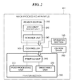
- FIG. 2 is a block diagram of an image processing apparatus according to a first embodiment of the present invention.
- FIG. 3 is a view showing the internal construction of the image processing apparatus.
- FIG. 4 is a detailed block diagram of a reader image processor of the image processing apparatus.
- FIG. 5 is a detailed block diagram of a controller of the image processing apparatus.
- FIG. 6 is a detailed block diagram of an image processing part of a scanner interface circuit of the controller of the image processing apparatus.
- FIG. 7 is a detailed block diagram of an ACS counter of the scanner interface circuit.
- FIG. 8 is a detailed block diagram of an image processing part of a printer interface circuit of the controller of the image processing apparatus.
- FIG. 9 is a detailed block diagram of a graphic processor of the controller of the image processing apparatus.
- FIG. 10 is a view of an example of a configuration screen as a user interface.
- FIG. 11 is a view of a copy image obtained by superimposing a clear-toner image on an original image.
- FIG. 12 is a diagram of the data structure of clear-toner image information.
- FIG. 13 is a diagram useful in explaining a method of performing clear-toner printing based on attribute data.
- FIG. 14 is a schematic diagram of a system in which the image processing apparatus writes image data and detailed job information into a storage server.
- FIG. 15 is a diagram of an example of a history record stored in the storage server.
- FIG. 16 is a flowchart of a copy output job process executed by the image processing apparatus.
- FIG. 17 is a flowchart of a PDL print output job process executed by the image processing apparatus.
- FIG. 18 is a flowchart of an attribute data transmission process for transmitting clear-toner attribute data from the image processing apparatus to a security unit.
- FIG. 19 is a view of a configuration screen of an image processing apparatus according to a second embodiment of the present invention, as a user interface for specifying whether or not to perform synthesis of image data for recording.
- FIG. 20 is a flowchart of a recording image data transmission process for transmitting image data for recording from the image processing apparatus to the security unit.
- FIG. 1 is a schematic diagram of the basic system configuration for realizing the function of recording job history information in the image processing apparatus according to the present embodiment.
- the present system is formed by interconnecting image processing apparatuses 101 and 102, a database/mail server 103, information apparatuses 104 and 111, a storage server 105, a history management server 109, and an authentication server 106, via a network.
- each of the image processing apparatuses 101 and 102 when each of the image processing apparatuses 101 and 102 performs printing or copying, it accumulates all printed image data and all image data read from an original in the storage server 105. This realizes the function of the image processing apparatus, for recording job history information indicative of what kind of processing was carried out on image data by whom, and when and where is realized.
- the user In the case of executing a print job, a copy job or the like by the image processing apparatus 101, the user inserts an IC card of the user's own into an IC card reader 122 connected to the image processing apparatus 101, whereby user authentication is made possible.
- This user authentication makes it possible to identify the user who carried out the print job, the copy job or the like.
- the database/mail server 103 is a computer on which operates an application server for storing data read from originals by the image processing apparatus 101.
- the authentication server 106 performs user authentication.
- the information apparatus 104 is a computer connected to the database/mail server 103 to download data from the database/mail server 103 and display the downloaded data.
- the information apparatus 104 is capable of giving a necessary print instruction to the image processing apparatus 101.
- the information apparatus 104 causes the image processing apparatus 101 to perform printing
- the user's name and password entered via a keyboard of the information apparatus 104 are delivered to the authentication server 106, and the authentication server 106 executes user authentication.
- the image processing apparatus 101 is enabled to perform print processing.
- the storage server 105 is an audit storage device for recording and accumulating all image data input and output by the image processing apparatus 101, together with detailed information on an associated job.
- the storage server 105 records and manages the detailed job information as a history record (job history event).
- the history management server 109 compiles data stored in the storage server 105.
- the history management server 109 Under an environment where a plurality of image processing apparatuses and storage servers exist, centralized management of data recorded for security is made possible by installation of the history management server 109. Further, when the history management server 109 performs OCR (Optical Character Recognition) processing on an image and detects any of specific keywords, it is judged that there is a fear of information leakage. In this case, it is possible to notify a system administrator of the fact by e-mail.
- OCR Optical Character Recognition
- the image processing apparatus 102 has a function equivalent to that of the storage server 105 incorporated therein. More specifically, the image processing apparatus 102 is provided with an audit storage device for recording and accumulating all image data input and output by the image processing apparatus 102, together with detailed information on an associated job.
- the information apparatus 111 is connected to the image processing apparatus 102 to give a printout instruction and an Internet FAX (hereinafter abbreviated as "IFAX") instruction to the image processing apparatus 102.
- IFAX Internet FAX
- a user inserts an IC card of the user's own into an IC card reader 123 connected to the image processing apparatus 111, whereby user authentication is made possible.
- An Ethernet (registered trademark) 107 is a network to which are connected the image processing apparatus 101, the database/mail server 103, the information apparatus 104, the storage server 105, and the history management server 109. Further, an Ethernet (registered trademark) 108 is a network to which are connected the image processing apparatus 102 and the information apparatus 111. The Ethernet (registered trademark) 107 and the Ethernet (registered trademark) 108 are interconnected via a WAN (Wide Area Network) 120. The network is not limited to the configuration shown in FIG. 1 .
- FIG. 2 is a block diagram of the image processing apparatus 101.
- the image processing apparatus 101 is comprised of a controller 500, a reader section (image input section) 200, a printer section (image output section) 300, an operating section 150, and a CD-ROM drive 260.
- the image processing apparatus 101 is a multifunction machine equipped with an original reading function, a printing function, and a communication function.
- the reader section 200 is comprised of a scanner unit 240, and a document feed unit 250.
- the scanner unit 240 has a function for reading originals and includes a CCD 210 described hereinafter.
- the document feed unit 250 has a function for conveying originals set therein onto an original platen glass 203 (see FIG. 3 ).
- the reader section 200 optically reads an image from an original conveyed by the document feed unit 250, and converts the image into image data.
- the printer section 300 (image forming means) is comprised of a printing unit 310, a sheet feed unit 320, and a post-processing unit 370.
- the printing unit 310 has a printing function for transferring and fixing an image on a sheet.
- the sheet feed unit 320 is comprised of a plurality of kinds of sheet cassettes, and feeds sheets into the printing unit 310.
- the post-processing unit 370 has a function for performing post-processing (sorting, stapling, etc.) on printed sheets and discharging the processed sheets out of the apparatus.
- the printer section 300 causes the printing unit 310 to print image data as a visualized image on each sheet conveyed by the sheet feed unit 320, and causes the post-processing unit 370 to discharge the sheets out of the apparatus.
- the controller 500 is electrically connected to the reader section 200 and the printer section 300.
- the controller 500 controls the reader section 200 to provide the original reading function for reading an image from an original, and controls the printer section 300 to provide the printing function for forming an image on a sheet. Further, the controller 500 is capable of reading data stored in a CD-ROM via the CD-ROM drive 260.
- the operation section 150 includes a liquid crystal display and a touch panel input section, and provides user interface (hereinafter abbreviated as "I/F") for operating the devices of the image processing apparatus under the control of the controller 500.
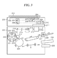
- FIG. 3 is a view showing the internal construction of the image processing apparatus.
- the reader section 200 is configured to read an image from an original and perform digital signal processing on the image.
- the printer section 300 is configured to print an image corresponding to the original image read by the reader section 200, in full color.
- an original 204 placed on the original platen glass (hereinafter simply referred to as “the platen glass”) 203 via a mirror-surface pressure plate 201 is irradiated with light from a lamp 205.
- a reflected light from the original is guided by mirrors 206, 207, and 208 to pass through a lens 209 to form an image on a 3-line solid-state imaging device sensor (hereinafter referred to as "the CCD") 210.
- the reflected light from the original is photoelectrically converted by the CCD 210, and three red (R), green (G), and blue (B) image signals as full-color information are sent to a reader image processor 211.
- An optical unit including the lamp 205 and the mirror 206 and an optical unit including the mirrors 207 and 208 are mechanically driven by a drive mechanism to move at a velocity of v and a velocity of 1/2v, respectively, in a direction orthogonal to an electrical scanning direction (main scanning direction) of the CCD 210, whereby the entire surface of the original 204 is scanned (sub-scanned).
- the original 204 is read e.g. at a resolution of 600 dpi (dots/inch) in both the main scanning direction and the sub scanning direction by the reader section 200.
- Read image signals are accumulated in a data storage within the reader image processor 211 in units of one original page.
- An image signal input to the reader image processor 211 is subjected to predetermined processing to be output to the controller 500.
- the image signal input to the controller 500 is electrically processed on a pixel-by-pixel basis to be separated into components of magenta (M), cyan (C), yellow (Y), and black (K) and sent to the printer section 300 together with a clear-toner signal (CL).
- M magenta
- C cyan
- Y yellow
- K black
- a laser driver 212 modulation-drives a semiconductor laser 213 according to the image signals (M, C, Y, and K) and the clear-toner signal (CL) delivered from the controller 500.
- a laser beam emitted from the semiconductor laser 213 scans the surface of a photosensitive drum 217 via a polygon mirror 214, an f- ⁇ lens 215, and a mirror 216.
- an electrostatic latent image is formed on the photosensitive drum 217 at the same resolution of 600 dpi (dots/inch) in both the main and sub scanning directions as in the case of reading the original.
- a rotary developing device 218 is comprised of a magenta developing section 219, a cyan developing section 220, a yellow developing section 221, a black developing section 222, and a clear developing section 223.
- the five developing sections 219 to 223 alternately come into contact with the photosensitive drum 217 to develop the electrostatic latent image formed on the same, using four color toners.
- a transfer drum 224 comes into contact with the photosensitive drum 217 and transfers the electrostatic latent image developed on the photosensitive drum 217 onto a sheet fed from a sheet cassette 225 or 226 and conveyed in a direction indicated by arrows in FIG. 3 to be wound around the transfer drum 224.
- the five colors i.e. the M, C, Y, K, and transparent (clear) toners are sequentially transferred onto the sheet (transfer material), whereafter the sheet is conveyed by a conveying mechanism comprising the sheet feed unit 320 to a fixing unit 227 and the image transferred on the sheet is fixed.
- the completely printed sheet is discharged onto a discharge tray 230.
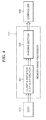
- FIG. 4 is a detailed block diagram of the reader image processor 211 of the image processing apparatus.
- the reader image processor 211 is comprised of a clamp & amplifier & S/H (sample-hold) & A/D (analog-digital conversion) section 401, and a shading section 402.
- An original on the platen glass 203 is read by the CCD 210, and reflected light from the original is converted into an electric signal.
- the CCD 210 is a color sensor
- R, G, and B color filters may be mounted on one CCD line in an inline form in the order of R, G, and B, or R, G, and B filters may be respectively arranged on three CCD lines, side by side.
- on-chip filters may be used, or filters may be formed independently of the CCD.
- the electric signals (analog image signals) output from the CCD 210 are input to the reader image processor 211.
- the clamp & amplifier & S/H & A/D section 401 of the reader image processor 211 sample-holds (S/H) the analog image signals, clamps the dark level of each of the analog image signals to a reference potential, and amplifies the analog image signals to a predetermined amount.
- the clamp & amplifier & S/H & A/D section 401 A/D converts the analog image signals into R, G, and B digital signals each consisting e.g. of eight bits.
- the processing order is not limited to that represented by the section name of the clamp & amplifier & S/H & A/D section 401.
- the shading section 402 performs shading correction and black correction on the 8-bit R, G, and B digital signals (RGB signals), followed by outputting these to the controller 500.
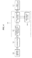
- FIG. 5 is a detailed block diagram of the controller 500 of the image processing apparatus.
- the controller 500 includes a main controller 511, a DRAM 116, a graphic processor 135, a scanner I/F circuit 140, and a printer I/F circuit 145.
- the controller 500 shown in FIG. 5 is an example of an arrangement for realizing generation means, synthesis means, control means, first image processing means, second image processing means third image processing means, and record means, according to the present invention.
- the main controller 511 is basically comprised of a CPU 512, a bus controller 513, and various kinds of I/F controller circuits (not shown).
- the CPU 512 and the bus controller 513 control the overall operation of the controller 500.
- the main controller 511 causes the CPU 512 to execute processes, described hereinafter with reference to respective flowcharts, based on a program.
- the CPU 512 of the main controller 511 operates based on the program read from a ROM 114 via a ROM I/F 115.
- the program also describes operation of the image processing apparatus for interpreting PDL code data received from an information apparatus and converting the PDL code data into image data and attribute data. This processing operation is performed by software.
- the bus controller 513 is configured to control transfer of data input/output via each I/F, and performs arbitration between a plurality of devices when they desire to use the bus simultaneously and control of DMA data transfer.
- the DRAM 116 is connected to the main controller 511 via a DRAM I/F 117.
- the DRAM 116 is used as a work area for the CPU 512 or a storage area for accumulating image data and attribute data. Further, the DRAM 116 stores clear-toner print data (see FIG. 12 ) described hereinafter.
- a Codec (Code Decoder) 118 compresses image data and attribute data accumulated in the DRAM 116 by one of compression methods including MH, MR, MMR, JBIG, and JPEG, or expands compressed and accumulated code data into image data and attribute data.
- the Codec 118 is connected to the main controller 511 via an I/F 520. Data transfer between the Codec 118 and the DRAM 116 is controlled by the bus controller 513, whereby DMA transfer is enabled.
- a SRAM 119 is used as a temporary work area for the Codec 118.
- the graphic processor 135 performs processing, such as image rotation, image magnification, color space conversion, or binarization, on image data accumulated in the DRAM 116.
- the graphic processor 135 is connected to the main controller 511 via an I/F 137.
- DMA transfer is performed by the bus controller 513 controlling data transfer between the graphic processor 135 and the DRAM 116.
- a SRAM 136 is used as a temporary work area for the graphic processor 135.
- a network controller 521 is connected to the main controller 511 via an I/F 523. Further, the network controller 521 is connected to an external network via a connector 522. The external network is generally implemented by an Ethernet (registered trademark).
- a general-purpose high-speed bus 125 connects between an expansion connector 124 for connection of an expansion board and an I/O controller 126. The general-purpose high-speed bus is generally implemented by a PCI bus.
- the I/O controller 126 includes two channels of asynchronous serial communication controllers 127 for transmitting and receiving control commands to and from the respective CPUs of the reader section 200 and the printer section 300.
- the I/O controller 126 is connected to the scanner I/F circuit 140 and the printer I/F circuit 145 by an I/O bus 128.
- a panel I/F 132 is connected to an LCD controller 131.
- the panel I/F 132 is comprised of an interface for enabling display on a liquid crystal screen of the operating section 150 and a key input I/F 130 for enabling input via a touch panel or hard keys.
- the operating section 150 is comprised of a liquid crystal display, a touch panel input section affixed to the liquid crystal display, and a plurality of hard keys.
- a signal input via the touch panel or a hard key is transmitted to the CPU 512 of the main controller 511 via the panel I/F 132.
- the liquid crystal display displays image data sent via the panel I/F 132, and configuration screens for configuring settings for operations of the image processing apparatus.
- a real-time clock module 133 updates and stores the date and time managed by the image processing apparatus.
- the real-time clock module 133 is backed up by a backup battery 134.
- An E-IDE interface 161 is provided for connection between the image processing apparatus and an external storage device.
- a hard disk drive 160 is connected to the image processing apparatus via the E-IDE I/F 161, whereby an operation for storing image data in a hard disk 162 and an operation for reading image data from the hard disk 162 are carried out.
- the hard disk 162 serves as a storage device for recording and accumulating all input and output image data together with detailed information on a job associated with the image data.
- a connector 142 is connected to the reader section 200.
- the connector 142 is comprised of a synchronous serial I/F 143 and a video I/F 144.
- a connector 147 is connected to the printer section 300.
- the connector 147 is comprised of a synchronous serial I/F 148 and a video I/F 149.
- the scanner I/F circuit 140 is connected to the reader section 200 via the connector 142. Further, the scanner I/F circuit 140 is connected to the main controller 511 via a scanner bus 141.
- the scanner I/F circuit 140 has the function of performing predetermined processing on image data received from the reader section 200 and the function of outputting to the scanner bus 141 a control signal generated based on a video control signal sent from the reader section 200. Data transfer from the scanner bus 141 to the DRAM 116 is controlled by the bus controller 513.
- the printer I/F circuit 145 is connected to the printer section 300 via the connector 147. Further, the printer I/F circuit 145 is connected to the main controller 511 via a printer bus 146.
- the printer I/F circuit 145 has the function of performing predetermined processing on image data output from the main controller 511 and outputting the processed image data to the printer section 300, and the function of outputting to the printer bus 146 a control signal generated based on a video control signal sent from the printer section 300.
- Image data loaded in the DRAM 116 is DMA-transferred to the printer section 300 via the printer bus 146 and the video I/F 149 under the control of the bus controller 513.
- FIG. 6 is a detailed block diagram of an image processing part of the scanner I/F circuit 140 of the controller 500 of the image processing apparatus.
- the scanner I/F circuit 140 is comprised of a binding & MTF correction section 601, an input masking section 602, and an auto color select (hereinafter acronymized as ACS) count section 603.
- the binding & MTF correction section 601 performs binding and MTF correction on an image signal delivered from the reader section 200 via the connector 142.
- the binding correction is performed for adjusting delay amounts of the respective lines in accordance with read speed, and correcting signal timing so as to make the read positions on the three lines coincident with each other.
- MTF Modulation Transfer Function
- Digital signals having undergone read position and timing correction by the binding & MTF correction section 601 are output to the input masking section 602.
- the input masking section 602 corrects the spectral characteristics of the CCD 210 and the spectral characteristics of the lamp 205 and the mirrors 206 to 208 based on the digital signals.
- Output signals from the input masking section 602 are sent to the ACS count section 603 and the main controller 511.
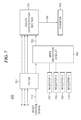
- FIG. 7 is a detailed block diagram of the ACS counter 603 of the scanner I/F circuit 140.
- the ACS counter 603 is comprised of a filter 701, an area detection circuit 702, a color determination section 703, a counter 704, a register 1 707, a register 2 708, a register 3 709, and a register 4 710.
- ACS determination is performed to determine whether an original is color or monochrome. More specifically, the chroma of each of pixels constituting an original image is obtained, and color/monochrome determination is performed based on the number of pixels having chroma exceeding a predetermined threshold value.
- a monochrome original has numerous color pixels on or near the edge thereof due to the influence of the MTF or the like, which makes it difficult to perform ACS determination simply in units of pixels.
- the filter 701 of the ACS count section 603 is for use in color determination by the color determination section 703, and has a FIFO structure so as to refer to surrounding pixels in association with the target pixel.
- the area detection circuit 702 generates an area signal 705 for performing ACS processing, based on values set in the respective registers 1 707 to 4 710 by the main controller 511 and a video control signal 712 sent from the reader section 200.
- the color determination section 703 determines whether each target pixel is color or monochrome by referring to surrounding pixels associated therewith in a memory of the filter 701, to thereby generate color determination signals 706.
- the counter 704 counts the number of the color determination signals 706 output from the color determination section 703.
- the main controller 511 determines an area, in which ACS processing is to be executed, of a read range of an original, and sets the aforementioned values (for setting the area) in the respective registers 1 707 to 4 710 (in the present embodiment, the range is determined independently of an original). Further, the main controller 511 compares the count of the counter 704 indicative of the number of the color determination signals 706 within the area in which ACS processing is to be executed, with a predetermined threshold value, to thereby determine whether the original is color or monochrome.
- Main-scanning and sub-scanning positions in which the color determination section 703 starts the determination and ends the same are set in advance in the respective registers 1 707 to 4 710, by the aforementioned values corresponding to opposite ends of the area in the main-scanning direction and the sub-scanning direction, based on the video signal 712 sent from the reader section 200.
- the area is defined by determination start positions and determination end positions set such that they are approximately 10 mm smaller than the actual size of an original.
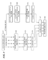
- FIG. 8 is a detailed block diagram of an image processing part of the printer I/F circuit 145 of the controller 500 of the image processing apparatus.
- the printer I/F circuit 145 is comprised of a color conversion section 802, ⁇ correction sections 803 and 810, filter sections 804 and 811, an attribute data input section 805, and a clear-toner signal-generating section 806.
- Image data and attribute data are delivered from the main controller 511 to the printer I/F circuit 145 via the printer bus 146 through respective different channels shown in FIG. 8 .
- the image data sent from the main controller 511 is input to the color conversion section 802.
- the color conversion section 802 converts the image data into C, M, Y, and K signals as color space signals for printout, on a pixel-by-pixel basis. In a case where image data is sent from the main controller 511 as C, M, Y, and K signals, color conversion by the color conversion section 802 is not performed.
- the ⁇ correction section 803 adjusts the density of the image data.
- the filter section 804 carries out smoothing or edge processing on the image data subjected to density adjustment by the ⁇ correction section 803. The image data having undergone the above-mentioned processing is delivered to the printer section 300.
- the attribute data sent from the main controller 511 is input to the attribute data input section 805.
- the attribute data input section 805 analyzes where in the image to superimpose, i.e. additionally apply clear toner, based on clear toner-superimposing position information contained in the attribute data.
- the clear-toner signal-generating section 806 generates a clear-toner signal for a position for superimposition of the clear toner, based on the analysis by the attribute data input section 805.
- the ⁇ correction section 810 performs density adjustment of the clear-toner signal.
- the filter section 811 carries out smoothing or edge processing on the clear-toner signal subjected to density adjustment.
- the clear-toner signal having undergone the above-mentioned processing is delivered to the printer section 300.
- the C, M, Y, and K signals and the clear-toner signal are supplied to the printer section 300 without being synthesized into an image signal (image data).
- the C, M, Y, and K signals and the clear-toner signal are not synthesized into an image until the printer section 300 superimposes C, M, Y, and K toners and clear toner one upon another to thereby form a toner image.
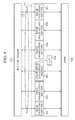
- FIG. 9 is a detailed block diagram of the graphic processor 135 of the controller 500 of the image processing apparatus.
- the graphic processor 135 is comprised of an image rotation section 901, an image magnification section 902, a color space conversion section 903, an image binarization section 905, an image multi-valuing section 906, and an image synthesis section 907. Further, the color space conversion section 903 includes a LUT (Look Up Table) 904.
- the SRAM 136 is used as a temporary work area for each of the above-mentioned modules of the graphic processor 135. The work area is statically allocated to the modules in advance so as to prevent one work area of the SRAM 136 from being simultaneously used by a plurality of modules.
- the graphic processor 135 is connected to the bus controller 513 of the main controller 511 via the I/F 137. Between the graphic processor 135 and the DRAM 116, data is DMA-transferred under the control of the bus controller 513.
- the bus controller 513 performs control for setting a mode and the like in each of the modules of the graphic processor 135 and timing control for transferring image data to the modules.
- FIG. 10 is a view of an example of a configuration screen as a user interface.
- the configuration screen as a user interface is displayed on the liquid crystal display of the operating section 150 of the image processing apparatus, or on a remote operation screen or a printer driver screen of an information apparatus connected to the image processing apparatus via the network.
- Items configurable on the configuration screen displayed on the operating section 150 are a specific character string 1001, an arbitrary character string 1002, a date 1003, a user ID 1004, a size 1005, an inclination 1006, and a file designation 1008.
- the specific character string 1001, the arbitrary character string 1002, the date 1003, and the user ID 1004 are each configured such that whether or not to output the same can be selected using an associated checkbox.
- the specific character string 1001 and the date 1003 are set to "YES”.
- the specific character string 1001 is used to output a predetermined character string, and is configured such that one of character strings, such as "Confidential”, “Top Secret”, and “Copy Prohibited", can be selected from an associated pull-down menu.
- the arbitrary character string 1002 is used to designate an arbitrary character string.
- a soft keyboard is displayed to enable input of a desired character string.
- An entered character string is displayed in a textbox.
- the date 1003 is used to output a date on which an operation is performed, and is configured to be automatically displayed by a clock incorporated in the image processing apparatus.
- the user ID 1004 is used to output the user ID of a user currently using the image processing apparatus. If an associated checkbox is checked, the user's ID code is automatically displayed when the user logs in to the image processing apparatus.
- the size 1005 and the inclination 1006 are used to designate a form of an image to be printed out. In the present example, it is possible to designate the size and inclination of a character string in respective associated pull-down menus.
- the file designation 1008 is used to designate a document file or an image file to be superimposed on the image to be printed out. When a right-hand reference button is pressed, a file tree is displayed to enable designation of a desired file. When a file is designated, it is displayed in an associated textbox. A printout to be actually obtained by carrying out printing on a sheet according to the items set as described above can be checked on a preview screen 1007 in advance.
- FIG. 11 is a view of a copy image formed by superimposing a clear-toner image on an original image.
- reference numeral 1101 denotes the original image as a base
- reference numeral 1102 the copy image.
- the copy image 1102 is formed by superimposing the clear-toner image on the original image 1101 read from an original by the reader section 200 and having undergone various kinds of image processing.
- the clear-toner image is formed by "Copy Prohibited" and an operation date which are selected and set on the FIG. 10 configuration screen as the user interface.
- the clear-toner image superimposed on the copy image 1102, i.e. the character strings ("Copy Prohibited” and "2004.10.10") designated by the user on the FIG. 10 configuration screen are formed using clear toner, and in actuality, therefore, the character strings cannot be easily perceived as an image.
- the glossiness of the clear toner used to print the character strings makes it possible to perceive the character strings.
- FIG. 12 is a diagram of the structure of clear-toner print data.
- the clear-toner print data is stored in the DRAM 116 of the controller 500 based on settings configured on the FIG. 10 configuration screen displayed on the operating section 150.
- the clear-toner print data is configured on the printer driver screen of the information apparatus 104, and the image processing apparatus receives the clear-toner print data from the information apparatus 104 via the network 107 or 108 together with print data, and stores the same in the DRAM 116.
- Clear-toner image information 1201 shows the data structure of information (clear-toner print data) required for clear-toner printing in the form of a table.
- Reference numeral 1202 denotes information indicative of whether or not to perform clear-toner printing. If "Not Perform” is designated, detailed information (attribute information) items 1203 et seq. are not necessary.
- the reference numeral 1203 denotes an attribute indicative of whether or not to perform clear-toner printing on the entire surface of a sheet. If “Perform” is designated, information items 1204 et seq. are to be excluded and hence unnecessary.
- the reference numeral 1204 denotes an attribute indicative of whether to partially superimpose or not superimpose clear toner on an original image. When it is determined from the attribute data and the like on the pixels of the original image to perform printing on an original image using clear toner to thereby express metal gloss, "Superimpose" is set.
- Reference numeral 1205 denotes an attribute indicative of whether or not to print a character string using clear toner. If the character string is to be printed using clear toner, "Print" is set. There may be provided character string information including information items, such as character string content 1206, point 1207, font 1208, and inclination 1209.
- Reference numeral 1210 denotes an attribute indicative of whether or not to additionally designate a file to be printed using clear toner. If a file is to be additionally designated, "Designate” is set.
- Reference numeral 1211 denotes file information which is required when a file is designated, and the file information 1211 specifies a path to the file for identifying the file.
- FIG. 13 is a diagram useful in explaining a method of performing clear-toner printing based on attribute data.
- FIG. 13 there is shown a case where PDL data comprised of image data 1302 and attribute data 1303 is input to the image processing apparatus from the information apparatus 104. More specifically, data which the image processing apparatus has received from the information apparatus 104 is converted into PDL data comprised of the image data 1302 having four Y, M, C, and K planes and the attribute data 1303. In this case, when information for superimposing a clear-toner image on the image to be printed is registered via the FIG. 10 configuration screen as a user interface, attribute data required for superimposition of the clear-toner image is generated.
- the attribute data 1303 includes clear-toner attribute data (i.e. the clear-toner print data shown in FIG. 12 ) and other attribute data.
- the other attribute data is information indicative of which of a character string, an image, and graphics is formed by pixels constituting the image data 1302, i.e. information for specifying an image area.
- Reference numeral 1304 denotes image data information included in the image data 1302 comprised of the YMCK planes.
- Reference numeral 1305 denotes clear-toner signal information included in the attribute data 1303. The image processing apparatus superimposingly prints a clear-toner image on a sheet 1306 based on the information 1304 and 1305.
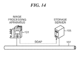
- FIG. 14 is a schematic diagram of a system in which the image processing apparatus 101 writes image data and detailed job information into a storage server 105.
- FIG. 14 illustrates an example of how the image processing apparatus 101 writes image data and detailed information (history record: job history event) on a job processed by the image processing apparatus 101 into the storage server 105 (external record unit).
- the network is implemented by the Ethernet (registered trademark) 107.
- the image processing apparatus 101 stores image data and detailed job information in the storage server 105 using SOAP (Simple Object Access Protocol).
- SOAP Simple Object Access Protocol
- encryption may be executed using e.g. SSL (Secure Sockets Layer), as required.
- Data in the storage server 105 may be encrypted and stored. Further, although in the present embodiment, the image processing apparatus 101 and the storage server 105 are provided separately, the image processing apparatus 101 may incorporate the function of the storage server 105. In the present embodiment, configuration information required for access to the storage server 105 is protected such that only the system administrator of the image processing apparatus 101 is authorized to configure the information.
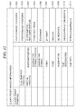
- FIG. 15 is a diagram of an example of a history record stored in the storage server 105.
- rows denoted by reference numerals 1501 to 1510 correspond to respective items of the history record.
- items job kind to copy count
- Boxes of a "tag name” column each store an item-specific tag name for identifying associated data.
- the column of Example 1 shows examples of record information.
- the item 1501 stores a job kind which shows a kind of job, such as COPY, FAX, or PDL.
- a tag name associated therewith is [JobKind].
- the item 1502 stores a job name which shows a name of an executed job.
- a tag name associated therewith is [JobName].
- the item 1503 stores a job client which shows a user name associated with the executed job.
- a tag name associated therewith is [ClientName].
- the item 1504 stores character code Information which shows a character code used in the present record.
- a tag name associated therewith is [CharacterCode].
- the item 1505 stores a section code which shows the section number of a section to which the user belongs.
- a tag name associated therewith is [SectionNo].
- the item 1506 stores a job start time (communication start time) which shows the start time of the job.
- a tag name associated therewith is [StartTime].
- the item 1507 stores a job end time (Communication End Time) which shows the end time of the job.
- a tag name associated therewith is [EndTime].
- the item 1508 stores a job end result which shows a final result of the job, such as "OK" or "Canceled".
- a tag name associated therewith is [Result].
- the item 1509 stores a sheet count per copy which shows how many pages are to be printed in the job.
- a tag name associated therewith is [ResourceCount].
- the item 1510 stores a copy count which shows how many copies are to be output.
- a tag name associated therewith is [Copies].
- FIG. 16 is a flowchart of a copy output job process executed by the image processing apparatus.
- a step S1001 when settings configured for a copy output job by a user via the operating section 150 are received, the main controller 511 of the controller 500 detects that copy settings have been configured.
- the copy settings include a copy count, a sheet size, single-sided copying/bookbinding as to whether to perform copying on only one side of each sheet and whether to bind copied sheets, an enlargement or reduction ratio set for copying, a setting as to whether or not to perform sort output of copied sheets, and a setting as to whether or not to perform stapling.
- settings as to an image to be superimposed using clear toner may be configured using the FIG. 10 configuration screen. In this case, the attribute data including clear-toner attribute data is generated by the CPU 512.
- the main controller 511 accepts a copy start instruction issued by the user via the operating section 150, and causes the CPU 512 to control the reader section 200 via the scanner I/F 140 and the connector 142 to read an image from an original.
- the image data read from the original by the reader section 200 is stored in the DRAM 116.
- magnification processing in the sub scanning direction is achieved by changing the moving speed of an optical unit according to an enlargement or reduction ratio (i.e. a magnification in the sub scanning direction) set for copying.
- an original image is read at 100% magnification irrespective of an enlargement or reduction ratio set for copying, and magnification processing in both the main scanning direction and the sub scanning direction is executed by the graphic processor 135.
- the main controller 511 transfers the image data read from the original by the reader section 200 and stored in the DRAM 116 to the graphic processor 135.
- the main controller 511 causes the graphic processor 135 to perform image processing on the image data based on the parameters set for copying. For example, when the enlargement ratio is set to 400% for copying, magnification processing in both the main scanning direction and the sub scanning direction is carried out using an image magnification section as a module in the graphic processor 135.
- the main controller 511 receives the image data having undergone the image processing and attribute data from the graphic processor 135, and stores the received image data and attribute data in the DRAM 116.
- the main controller 511 transfers the image data stored in the DRAM 116 to the printer section 300 in appropriate timing while controlling the printer section 300 via the printer I/F circuit 145 and the connector 147.
- a step S1007 the main controller 511 controls the printer section 300 to execute print output for forming an image corresponding to the image data on a sheet.
- the present process is terminated.
- a clear-toner image signal is generated based on clear-toner attribute data, and a clear-toner image formed based on the generated signal is superimposed on a full-color toner image formed by C, M, Y, and K toner images to thereby form an image on a sheet.
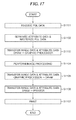
- FIG. 17 is a flowchart of a PDL print output job process executed by the image processing apparatus.
- the main controller 511 receives PDL data generated by driver software installed in the information apparatus 104, from the information apparatus 104 via the network.
- settings as to an image to be superimposed using clear toner may be configured using the FIG. 10 configuration screen displayed on the printer driver screen of the information apparatus 104.
- the main controller 511 separates the attribute data 1303 from the PDL data received from the information apparatus 104 and transferred via the connector 522 and the network controller 521. Further, the main controller 511 rasterizes the portion separated from the attribute data 1303 into the image data 1302. In a step S1103, the main controller 511 transfers the image data 1302 and the attribute data 1303 loaded in the DRAM 116 to the graphic processor 135.
- the main controller 511 causes the graphic processor 135 to carry out image processing on the image data.
- the main controller 511 causes the graphic processor 135 to rotate the image through 90 degrees. This makes it possible to perform image output according to a feedable sheet.
- the main controller 511 receives the image data having undergone the image processing and attribute data from the graphic processor 135, and stores the received image data and attribute data in the DRAM 116.
- the main controller 511 transfers the image data and the attribute data stored in the DRAM 116 to the printer section 300 in appropriate timing while controlling the printer section 300 via the printer I/F circuit 145 and the connector 147.
- the main controller 511 causes the printer I/F circuit 145 to carry out image processing on the image data and analyze the attribute data to generate the clear-toner signal 1305.
- the main controller 511 performs control such that a clear-toner image generated based on the clear-toner signal 1305 is superimposed on a predetermined portion of an image to be printed out.
- a step S1107 the main controller 511 controls the printer section 300 to execute print output for forming an image corresponding to the image data on a sheet.
- the present process is terminated.
- the C, M, Y, and K image data obtained by reading an original are sent to a security unit (the storage server within the image processing apparatus or the external storage server 105).
- a clear-toner signal which is not image data obtained by reading the original, is not sent to the security unit.
- the main controller 511 separates the clear-toner attribute data from the PDL data in the step S1103. More specifically, the clear-toner attribute data is separated as the attribute data 1303 appearing in FIG. 13 .
- C, M, Y, and K image data are sent to the security unit, whereas the clear-toner signal generated based on the attribute data 1303, which is not the C, M, Y, and K image data, is not.
- the clear-toner attribute data included in the attribute data is converted into image data, and then the image data obtained by the conversion from the attribute data is synthesized with the original image data. Thereafter, not only the image data but also the attribute data are sent to the security unit via the network.
- FIG. 18 is a flowchart of an attribute data transmission process for transmitting clear-toner attribute data from the image processing apparatus to the security unit.
- the FIG. 18 attribute data transmission process is executed as part of the step S1006 in FIG. 16 or part of the step S1106 in FIG. 17 .
- the main controller 511 extracts the clear-toner attribute data from the attribute data.
- the main controller 511 converts the extracted clear-toner attribute data into image data.
- the main controller 511 synthesizes rasterized image data (first image data) and image data (second image data) generated based on the clear-toner attribute data to generate image data for recording in the DRAM 116.
- the main controller 511 sends the recording image data stored in the DRAM 116 to the security unit, followed by terminating the present process.
- Image data to be sent from the image processing apparatus to the security unit may be provided by causing the graphic processor 135 to carry out image processing (e.g. resolution change or color space change) on image data input to the image processing apparatus.
- image processing e.g. resolution change or color space change
- image data which is obtained by causing the graphic processor 135 to synthesize third image data obtained by carrying out image processing on the first image data, and fourth image data obtained by carrying out image processing on the second image data may be sent to the security unit to be recorded therein.
- image data which is obtained by causing the graphic processor 135 to synthesize third image data obtained by carrying out image processing on the first image data, and fourth image data obtained by carrying out image processing on the second image data may be sent to the security unit to be recorded therein.
- image data obtained by carrying out image processing on the image data obtained by synthesizing the first image data and the second image data may be sent to the security unit for recording therein.
- a second embodiment of the present invention is distinguished from the above-described first embodiment by a point described below.
- the other elements in the present embodiment are identical to the corresponding ones in the first embodiment ( FIGS. 2 , 3 , 5 , and so forth), and therefore description thereof is omitted.
- rasterized image data and image data generated based on clear-toner attribute data are synthesized, and the synthesized image data is sent as recording image data to the security unit.
- rasterized image data and image data generated based on clear-toner attribute data can be separately sent as recording image data to the security unit.
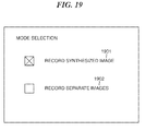
- FIG. 19 is a view of a configuration screen as a user interface for specifying whether or not to perform synthesis of recording image data in the second embodiment.
- the configuration screen as a user interface is displayed on the liquid crystal display of the operating section 150 of an image processing apparatus or on the remote operation screen or the printer driver screen of an information apparatus connected to the image processing apparatus via the network.
- the configuration screen displayed on the operating section 150 selecting unit
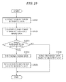
- FIG. 20 is a flowchart of a recording image data transmission process for transmitting image data for recording from the image processing apparatus to the security unit.
- the recording image data transmission process shown in FIG. 20 is executed in place of the attribute data transmission process in FIG. 18 in the first embodiment.
- the main controller 511 of the controller 500 extracts the clear-toner attribute data from the attribute data loaded in the DRAM 116 together with the rasterized image data in the step S1103 in FIG. 17 .
- the main controller 511 converts the extracted clear-toner attribute data into image data.
- the main controller 511 determines whether or not the user has selected the mode "record synthesized image" 1901 on the FIG. 19 configuration screen.
- step S2004 the main controller 511 synthesizes the rasterized image data and the image data generated based on the clear-toner attribute data, to thereby generate image data for recording in the DRAM 116.
- step S2005 the main controller 511 sends the recording image data in the DRAM 116 to the security unit via the network, followed by terminating the present process.
- step S2006 the main controller 511 separately sends the rasterized image data from the DRAM 116 and the image data generated based on the clear-toner attribute data from the DRAM 116 to the security unit, as respective recording image data items, via the network, and then terminates the present process.
- the security unit stores these two image data items and manages them in association with each other.
- the mode for separately sending the rasterized image data and the image data generated based on the clear-toner attribute data to the security unit More specifically, it is possible to select the mode enabling only a portion of the image having the clear-toner image superimposed thereon to be checked, so that a problem that the portion having the clear-toner image superimposed thereon is hidden behind the image formed based on the rasterized image data can be solved. This makes it possible to enhance secret security.
- the present invention may also be accomplished by supplying a system or an apparatus with a storage medium in which a program code of software, which realizes the functions of either of the above described embodiments, is stored, and causing a computer (or CPU or MPU) of the system or apparatus to read out and execute the program code stored in the storage medium.
- the program code itself read from the storage medium realizes the functions of either of the above described embodiments, and therefore the program code and the storage medium in which the program code is stored constitute the present invention.
- Examples of the storage medium for supplying the program code include a floppy (registered trademark) disk, a hard disk, a magnetic-optical disk, an optical disk, such as a CD-ROM, a CD-R, a CD-RW, a DVD-ROM, a DVD-RAM, a DVD-RW, or a DVD+RW, a magnetic tape, a nonvolatile memory card, and a ROM.
- the program may be downloaded via a network.
Landscapes
- Engineering & Computer Science (AREA)
- Physics & Mathematics (AREA)
- General Physics & Mathematics (AREA)
- Theoretical Computer Science (AREA)
- Human Computer Interaction (AREA)
- General Engineering & Computer Science (AREA)
- Microelectronics & Electronic Packaging (AREA)
- Computer Security & Cryptography (AREA)
- Multimedia (AREA)
- Signal Processing (AREA)
- Control Or Security For Electrophotography (AREA)
- Facsimiles In General (AREA)
- Facsimile Image Signal Circuits (AREA)
- Image Processing (AREA)
- Editing Of Facsimile Originals (AREA)
- Accessory Devices And Overall Control Thereof (AREA)
Applications Claiming Priority (1)
| Application Number | Priority Date | Filing Date | Title |
|---|---|---|---|
| JP2008159158A JP5264311B2 (ja) | 2008-06-18 | 2008-06-18 | 画像処理装置、制御方法、及びプログラム |
Publications (1)
| Publication Number | Publication Date |
|---|---|
| EP2136259A2 true EP2136259A2 (en) | 2009-12-23 |
Family
ID=41078277
Family Applications (1)
| Application Number | Title | Priority Date | Filing Date |
|---|---|---|---|
| EP09163011A Withdrawn EP2136259A2 (en) | 2008-06-18 | 2009-06-17 | Image processing apparatus, method of controlling the image processing apparatus, program, and storage medium |
Country Status (5)
| Country | Link |
|---|---|
| US (1) | US8630019B2 (enExample) |
| EP (1) | EP2136259A2 (enExample) |
| JP (1) | JP5264311B2 (enExample) |
| KR (1) | KR101151794B1 (enExample) |
| CN (1) | CN101609281B (enExample) |
Families Citing this family (9)
| Publication number | Priority date | Publication date | Assignee | Title |
|---|---|---|---|---|
| JP5063423B2 (ja) * | 2008-03-17 | 2012-10-31 | キヤノン株式会社 | 画像入出力装置及び画像入出力方法、並びにジョブ履歴記録システム |
| JP5464913B2 (ja) * | 2009-06-01 | 2014-04-09 | キヤノン株式会社 | 画像形成装置、情報処理装置、画像形成装置の制御方法、情報処理装置の制御方法及びプログラム |
| JP5630984B2 (ja) * | 2009-10-21 | 2014-11-26 | キヤノン株式会社 | 画像入出力装置及び画像入出力方法 |
| JP5537149B2 (ja) * | 2009-12-25 | 2014-07-02 | キヤノン株式会社 | 画像処理装置及びその制御方法、並びにプログラム |
| US9013719B2 (en) * | 2010-06-14 | 2015-04-21 | Xerox Corporation | Non-print mode in a multifunction printing device |
| US10277778B2 (en) * | 2014-06-24 | 2019-04-30 | Ec Data Systems Inc. | Audit logging for a secure, scalable and flexible internet fax architecture |
| US9544473B2 (en) * | 2014-10-20 | 2017-01-10 | Ricoh Company, Ltd. | Information processing system and information processing method |
| JP6720795B2 (ja) * | 2016-09-16 | 2020-07-08 | 株式会社リコー | 機器、情報処理装置、情報処理システム、情報処理方法、及びプログラム |
| JP7802817B2 (ja) * | 2021-03-01 | 2026-01-20 | ライカ マイクロシステムズ (スジョウ) テクノロジー カンパニー リミテッド | 処理装置、光学検査のための検査装置および対応する方法 |
Citations (1)
| Publication number | Priority date | Publication date | Assignee | Title |
|---|---|---|---|---|
| JPH1055085A (ja) | 1996-08-08 | 1998-02-24 | Fuji Xerox Co Ltd | カラー画像形成装置 |
Family Cites Families (22)
| Publication number | Priority date | Publication date | Assignee | Title |
|---|---|---|---|---|
| US6278486B1 (en) * | 1990-09-18 | 2001-08-21 | Canon Kabushiki Kaisha | Information signal controlling system |
| US5197765A (en) * | 1991-07-12 | 1993-03-30 | The Standard Register Company | Varying tone securing document |
| US5788285A (en) * | 1996-06-13 | 1998-08-04 | Wicker; Thomas M. | Document protection methods and products |
| EP1317734B1 (en) * | 2000-09-15 | 2005-02-16 | Trustcopy Pte Ltd | Optical watermark |
| KR20030093610A (ko) | 2002-06-03 | 2003-12-11 | 주식회사 마이디즈 | 문서출력시 보안 규칙기반의 접근제어 기능에 의한인증정보의 워터마크 표시 프린트 출력 방법 |
| JP4012050B2 (ja) * | 2002-11-27 | 2007-11-21 | キヤノン株式会社 | 情報処理装置、情報処理方法、制御プログラム |
| JP2004280227A (ja) * | 2003-03-13 | 2004-10-07 | E4C-Link Corp | 文書管理システム |
| JP3913237B2 (ja) * | 2003-10-10 | 2007-05-09 | キヤノン株式会社 | 情報処理装置および情報処理装置の制御方法 |
| JP3938176B2 (ja) * | 2003-12-10 | 2007-06-27 | キヤノン株式会社 | 画像処理方法、画像処理装置、プログラム及び記録媒体 |
| CN100495248C (zh) * | 2004-08-20 | 2009-06-03 | 株式会社理光 | 图像处理装置、图像处理方法和计算机产品 |
| JP2006092363A (ja) * | 2004-09-24 | 2006-04-06 | Canon Inc | 印刷制御プログラム、印刷制御方法、および情報処理装置 |
| EP2458498B1 (en) * | 2004-11-24 | 2015-07-29 | Canon Kabushiki Kaisha | Information processing apparatus, printing system, and control method therefor |
| US7236734B2 (en) * | 2005-02-22 | 2007-06-26 | Eastman Kodak Company | Method and apparatus for electrostatographic printing with enhanced color gamut |
| EP1739947B1 (en) * | 2005-06-30 | 2013-10-02 | Canon Kabushiki Kaisha | Density determination method, image forming apparatus, and image processing system |
| JP2007088603A (ja) * | 2005-09-20 | 2007-04-05 | Fuji Xerox Co Ltd | 画像処理装置、画像システム及び画像処理方法 |
| JP4137933B2 (ja) | 2005-10-31 | 2008-08-20 | シャープ株式会社 | 画像処理装置、プログラム、及び記録媒体 |
| JP4164510B2 (ja) * | 2005-12-22 | 2008-10-15 | キヤノン株式会社 | 画像処理装置、画像処理方法 |
| JP4870450B2 (ja) * | 2006-02-27 | 2012-02-08 | 株式会社日立ハイテクノロジーズ | 検査装置、および検査方法 |
| JP4164516B2 (ja) * | 2006-05-11 | 2008-10-15 | キヤノン株式会社 | 画像出力装置、履歴管理方法、および履歴管理プログラム |
| US7639400B2 (en) * | 2007-02-13 | 2009-12-29 | Xerox Corporation | Glossmark image simulation with application of background modified gloss effect image |
| WO2009040871A1 (ja) * | 2007-09-25 | 2009-04-02 | Fujitsu Limited | 画像合成装置及び方法 |
| JP5225348B2 (ja) * | 2010-09-27 | 2013-07-03 | シャープ株式会社 | 印刷システム、プリンタドライバ、画像形成装置、及び印刷方法 |
-
2008
- 2008-06-18 JP JP2008159158A patent/JP5264311B2/ja not_active Expired - Fee Related
-
2009
- 2009-06-12 US US12/483,340 patent/US8630019B2/en not_active Expired - Fee Related
- 2009-06-17 EP EP09163011A patent/EP2136259A2/en not_active Withdrawn
- 2009-06-17 KR KR1020090053860A patent/KR101151794B1/ko not_active Expired - Fee Related
- 2009-06-18 CN CN2009101500193A patent/CN101609281B/zh not_active Expired - Fee Related
Patent Citations (1)
| Publication number | Priority date | Publication date | Assignee | Title |
|---|---|---|---|---|
| JPH1055085A (ja) | 1996-08-08 | 1998-02-24 | Fuji Xerox Co Ltd | カラー画像形成装置 |
Also Published As
| Publication number | Publication date |
|---|---|
| CN101609281B (zh) | 2012-04-04 |
| JP5264311B2 (ja) | 2013-08-14 |
| KR101151794B1 (ko) | 2012-06-04 |
| US20090316170A1 (en) | 2009-12-24 |
| JP2010004124A (ja) | 2010-01-07 |
| CN101609281A (zh) | 2009-12-23 |
| US8630019B2 (en) | 2014-01-14 |
| KR20090131658A (ko) | 2009-12-29 |
Similar Documents
| Publication | Publication Date | Title |
|---|---|---|
| US8630019B2 (en) | Image processing apparatus, method of controlling the image processing apparatus, and storage medium | |
| US8508792B2 (en) | Image processing apparatus, an image processing method, and a program thereof for handling a copy-forgery-inhibited pattern image | |
| JP2006087075A (ja) | 画像処理装置、画像処理方法および画像処理プログラム | |
| KR100819995B1 (ko) | 화상 처리 장치 및 그 제어 방법, 및 기록 매체 | |
| US8027061B2 (en) | Security encoding unit and image forming apparatus including same | |
| US8363284B2 (en) | Image processing system for producing copy protected images using transparent recording material | |
| US7299233B2 (en) | Copying apparatus, method of controlling the same, and program for implementing the method | |
| US8576420B2 (en) | Image processing apparatus that can maintain security | |
| US7599081B2 (en) | Detecting and protecting a copy guarded document | |
| US8395812B2 (en) | Apparatus and method of concealing information of image data | |
| JP2007267419A (ja) | 画像処理装置、画像処理方法および画像処理プログラム | |
| JP2005111852A (ja) | 画像形成装置、印刷制御方法、及びプログラム | |
| JP2004094731A (ja) | 画像形成装置及び画像形成方法 | |
| JP2004153567A (ja) | 画像入出力装置及びその制御方法、画像入出力システム、及び制御プログラム | |
| JP2006014191A (ja) | 画像処理装置、画像処理方法、及びプログラム | |
| JP2005027037A (ja) | フォーマット変換方法及び画像処理装置 | |
| EP2001216A1 (en) | Security encoding unit and image forming apparatus including same | |
| JP2007174129A (ja) | 画像形成装置 | |
| JP2004032256A (ja) | 画像処理装置および画像処理装置の制御方法およびプログラムおよび記憶媒体 | |
| JP2008103919A (ja) | 画像形成装置及びその方法 | |
| JP2006116758A (ja) | 画像処理装置および画像処理方法およびコンピュータが読み取り可能なプログラムを格納した記憶媒体およびプログラム | |
| JP2005199492A (ja) | 画像処理装置 | |
| JP2006326869A (ja) | 画像処理装置及び画像処理方法 | |
| JP2007184880A (ja) | 画像処理装置及び画像処理システム | |
| JP2001352444A (ja) | 画像処理装置およびその方法 |
Legal Events
| Date | Code | Title | Description |
|---|---|---|---|
| PUAI | Public reference made under article 153(3) epc to a published international application that has entered the european phase |
Free format text: ORIGINAL CODE: 0009012 |
|
| AK | Designated contracting states |
Kind code of ref document: A2 Designated state(s): AT BE BG CH CY CZ DE DK EE ES FI FR GB GR HR HU IE IS IT LI LT LU LV MC MK MT NL NO PL PT RO SE SI SK TR |
|
| RIC1 | Information provided on ipc code assigned before grant |
Ipc: H04N 1/00 20060101ALI20120829BHEP Ipc: G03G 15/00 20060101AFI20120829BHEP Ipc: G06F 3/12 20060101ALI20120829BHEP Ipc: G03G 21/04 20060101ALI20120829BHEP |
|
| STAA | Information on the status of an ep patent application or granted ep patent |
Free format text: STATUS: THE APPLICATION HAS BEEN WITHDRAWN |
|
| 18W | Application withdrawn |
Effective date: 20121031 |