EP2135542B1 - Endoskop- und Schaftsystem - Google Patents
Endoskop- und Schaftsystem Download PDFInfo
- Publication number
- EP2135542B1 EP2135542B1 EP09007594A EP09007594A EP2135542B1 EP 2135542 B1 EP2135542 B1 EP 2135542B1 EP 09007594 A EP09007594 A EP 09007594A EP 09007594 A EP09007594 A EP 09007594A EP 2135542 B1 EP2135542 B1 EP 2135542B1
- Authority
- EP
- European Patent Office
- Prior art keywords
- endoscope
- shank
- sleeve
- access
- connection piece
- Prior art date
- Legal status (The legal status is an assumption and is not a legal conclusion. Google has not performed a legal analysis and makes no representation as to the accuracy of the status listed.)
- Active
Links
- 230000003287 optical effect Effects 0.000 description 9
- 210000002105 tongue Anatomy 0.000 description 7
- 239000011324 bead Substances 0.000 description 3
- 238000011010 flushing procedure Methods 0.000 description 3
- 238000004140 cleaning Methods 0.000 description 2
- 238000012423 maintenance Methods 0.000 description 2
- 239000013307 optical fiber Substances 0.000 description 2
- 238000001356 surgical procedure Methods 0.000 description 2
- 241000196324 Embryophyta Species 0.000 description 1
- 241000209035 Ilex Species 0.000 description 1
- 230000005540 biological transmission Effects 0.000 description 1
- 230000000740 bleeding effect Effects 0.000 description 1
- 230000015271 coagulation Effects 0.000 description 1
- 238000005345 coagulation Methods 0.000 description 1
- 239000004020 conductor Substances 0.000 description 1
- 230000001419 dependent effect Effects 0.000 description 1
- 238000006073 displacement reaction Methods 0.000 description 1
- 238000005286 illumination Methods 0.000 description 1
- 238000003780 insertion Methods 0.000 description 1
- 230000037431 insertion Effects 0.000 description 1
- 210000003928 nasal cavity Anatomy 0.000 description 1
Images


Classifications
-
- A—HUMAN NECESSITIES
- A61—MEDICAL OR VETERINARY SCIENCE; HYGIENE
- A61B—DIAGNOSIS; SURGERY; IDENTIFICATION
- A61B17/00—Surgical instruments, devices or methods, e.g. tourniquets
- A61B17/34—Trocars; Puncturing needles
- A61B17/3417—Details of tips or shafts, e.g. grooves, expandable, bendable; Multiple coaxial sliding cannulas, e.g. for dilating
- A61B17/3421—Cannulas
-
- A—HUMAN NECESSITIES
- A61—MEDICAL OR VETERINARY SCIENCE; HYGIENE
- A61B—DIAGNOSIS; SURGERY; IDENTIFICATION
- A61B1/00—Instruments for performing medical examinations of the interior of cavities or tubes of the body by visual or photographical inspection, e.g. endoscopes; Illuminating arrangements therefor
- A61B1/00112—Connection or coupling means
- A61B1/00121—Connectors, fasteners and adapters, e.g. on the endoscope handle
- A61B1/00128—Connectors, fasteners and adapters, e.g. on the endoscope handle mechanical, e.g. for tubes or pipes
-
- A—HUMAN NECESSITIES
- A61—MEDICAL OR VETERINARY SCIENCE; HYGIENE
- A61B—DIAGNOSIS; SURGERY; IDENTIFICATION
- A61B17/00—Surgical instruments, devices or methods, e.g. tourniquets
- A61B17/00234—Surgical instruments, devices or methods, e.g. tourniquets for minimally invasive surgery
- A61B2017/00238—Type of minimally invasive operation
- A61B2017/00261—Discectomy
-
- A—HUMAN NECESSITIES
- A61—MEDICAL OR VETERINARY SCIENCE; HYGIENE
- A61B—DIAGNOSIS; SURGERY; IDENTIFICATION
- A61B17/00—Surgical instruments, devices or methods, e.g. tourniquets
- A61B17/34—Trocars; Puncturing needles
- A61B17/3403—Needle locating or guiding means
- A61B2017/3405—Needle locating or guiding means using mechanical guide means
- A61B2017/3409—Needle locating or guiding means using mechanical guide means including needle or instrument drives
-
- A—HUMAN NECESSITIES
- A61—MEDICAL OR VETERINARY SCIENCE; HYGIENE
- A61B—DIAGNOSIS; SURGERY; IDENTIFICATION
- A61B17/00—Surgical instruments, devices or methods, e.g. tourniquets
- A61B17/34—Trocars; Puncturing needles
- A61B17/3417—Details of tips or shafts, e.g. grooves, expandable, bendable; Multiple coaxial sliding cannulas, e.g. for dilating
- A61B17/3421—Cannulas
- A61B2017/3445—Cannulas used as instrument channel for multiple instruments
-
- A—HUMAN NECESSITIES
- A61—MEDICAL OR VETERINARY SCIENCE; HYGIENE
- A61B—DIAGNOSIS; SURGERY; IDENTIFICATION
- A61B90/00—Instruments, implements or accessories specially adapted for surgery or diagnosis and not covered by any of the groups A61B1/00 - A61B50/00, e.g. for luxation treatment or for protecting wound edges
- A61B90/50—Supports for surgical instruments, e.g. articulated arms
Definitions
- the invention relates to an endoscope and shaft system for use in endoscopic spinal surgery, especially in the cervical spine.
- EP 0 455 188 A2 represents the closest prior art and discloses a coagulation instrument for nourishing bleeding in nasal cavities.
- This instrument has an access shaft, at the proximal end of a clutch housing is formed, in which a receptacle biased by a spring is held so that it is rotatable about its longitudinal axis in certain steps and to a certain extent against the spring bias axially displaceable.
- an endoscope optic is fixed by means of a clamping ring.
- This embodiment has the disadvantage that the removal of the endoscope optics releases on the one hand only a limited cross-section of the working channel and on the other hand the positioning of the endoscope is lost by loosening the clamping ring, so that the endoscope must be repositioned after reinserting into the instrument, especially in the axial direction ,
- the endoscope and shaft system according to the invention has an access shaft and an endoscope which can be inserted into the access shaft.
- the access shaft according to the invention has a handle part at its proximal end. This has the advantage that over the handle part manipulation forces can be transferred directly to the access shaft to position it in the operational area.
- the inserted endoscope remains free from the manipulation forces and is protected against damage. In this way, comparatively large manipulation forces can be transmitted without the endoscope having to be specially reinforced for this purpose.
- the endoscope can thus continue to be designed very slim adapted to the available small access channel, so that the available space can be optimally utilized.
- the endoscope is held by a connector.
- the endoscope is preferably detachably connected to the connecting piece.
- the connector in turn is detachably connected to the handle part or connectable.
- the connector may be disconnected from the handle and access shank together with the endoscope, for example to guide other instruments through the access shaft into the surgical field.
- the handling of the access shaft can be done solely on the directly connected to the access shaft handle.
- the connector when connected to the handle member, is rotatable about the longitudinal axis of the endoscope relative to the handle member. In this way, the endoscope can be rotated in the access shaft about its longitudinal axis, in order to be able to observe as large a region of the surgical field as possible with the endoscope.
- the endoscope is not only rotatable but also axially movable.
- Such axial mobility can be achieved, for example, by virtue of the fact that the connecting piece is not only rotatable relative to the grip part but also axially movable relative to the grip part.
- the endoscope is then moved axially together with the connecting piece and / or rotated to the distal End of the endoscope to place so that a desired area of the operating area can be considered.
- an endoscope and shaft system is thus created, which on the one hand enables the transmission of relatively large manipulation forces and on the other hand at the same time allows a, preferably free, mobility of the endoscope in the access shaft.
- the handle part and / or the connecting piece are designed such that the endoscope held in the connecting piece is arranged with its longitudinal axis offset parallel to the longitudinal axis of the access shaft.
- a free lumen is created in addition to the endoscope in the cross section of the access shaft, through which a working instrument can be guided through the access shaft to the operating area in addition to the endoscope.
- the access shaft has a cross-sectional shape which has a larger width in a first direction than in a second direction which is normal to the first direction. That is, the access shaft is not circular in cross section but substantially oval. This makes it possible to form the access shaft in cross section with the lowest possible height, so that it can be fed well into the area of the spinal column, in particular in the intervertebral space. At the same time a larger enough lumen in the interior of the access shaft is created by the larger cross-section width through which an endoscope and possibly other instruments can be supplied.
- the endoscope is preferably placed so that its longitudinal or central axis is offset parallel to the longitudinal or central axis of the access shaft. That is ideally located in the oval cross-section of the access shaft endoscope in one half and the other half forms a free lumen, by which, for example, a working instrument can be supplied.
- the access shaft is detachably connected to the handle part. This makes it possible to combine the instrument during insertion into the intervertebral space with other instruments and to disassemble for cleaning or maintenance purposes or, for example, to connect different access shafts with one and the same handle part. More preferably, the connection between the handle part and the access shaft is designed so that the access shaft can be connected in two possible angular positions with the handle part. That is, the access shaft can be rotated 180 degrees about its longitudinal axis in a second possible position with the handle portion. This allows for oval configuration of the access shaft and staggered arrangement of the endoscope to position the endoscope either in the two possible positions in Accessschaft.
- the connection between the handle part and access shaft is designed, for example, as a releasable ball detent connection.
- the handle portion has at its distal end a receptacle for the proximal end of the access shaft and has at its proximal end a receptacle for the connector, wherein these two receptacles are arranged offset parallel to each other in a direction transverse to the longitudinal axis of the access shaft.
- the handle provides for the staggered arrangement of endoscope and access shaft.
- the connector is positioned in the direction transverse to the longitudinal axis of the access shaft defined by the handle member.
- the rotatability of the endoscope about its longitudinal axis and preferably also an axial mobility of the endoscope in the access shaft remains ensured.
- the handle part and the connecting piece are detachably plugged together in the axial direction.
- This allows the connector to be easily removed from the handle portion to, for example, remove the endoscope connected to the connector from the access shaft. This may be necessary if the entire cross section of the access shaft is needed to remove larger amounts of tissue from the surgical field.
- the fact that the endoscope remains connected to the connector it is possible that the removal of the endoscope, the positioning of the endoscope is not lost. That is, when the connector is again plugged together with the handle portion, the endoscope is again in the same position as before the removal. This is ensured by positioning the endoscope over the connector, i. H. the connector has a positioning means for positioning the endoscope in the access shaft. This can include positioning in the axial direction and / or positioning with respect to the angular position of the endoscope about its longitudinal axis.
- the handle part preferably has at the proximal end a sleeve which engages from the distal end into the interior of the connecting piece. That is, the connector has at its distal end an opening which is adapted in size and cross-sectional shape of the shape and size of the outer periphery of the sleeve on the handle portion.
- the sleeve is circular cylindrical and the opening on the connecting piece is correspondingly cylindrical.
- the rotatability of the endoscope about its longitudinal axis is preferably achieved in that the sleeve of the handle part in the interior of the distal side Opening of the connector can rotate. That is, the connector rotates, preferably freely, on the sleeve on the handle portion.
- the connector has at its proximal end a mounting receptacle for releasably securing the endoscope. Through this attachment receptacle, the endoscope is defined and held on the connector. It is preferred that the endoscope for cleaning and maintenance purposes can be solved by the connector. Furthermore, this makes it possible that different endoscopes can be attached to one and the same connector.
- the detachable fastening of the endoscope is preferably possible in that the endoscope is releasably fixable by at least one contact surface of the fastening receptacle by means of a rotatable clamping ring with an inner diameter which changes over the circumference.
- the clamping ring is designed so that it is positioned in a released position so that a greater distance between the clamping ring and abutment surface is given, so that the endoscope is movable between the two. By turning the clamping ring, an area with a smaller inner diameter is brought to cover with the contact surface.
- the attachment receptacle is further preferably designed such that in addition to this non-positive clamping, a positive positioning of the endoscope is also provided in order to hold the endoscope in a defined position.
- the attachment receptacle is preferably formed by a sleeve which has a sector-shaped cut-out at the proximal end, wherein the end faces of the sleeve facing the cut-out bear contact surfaces form for the endoscope.
- the endoscope has a corresponding attachment portion, which can be inserted into this sector-shaped cutout.
- contact surfaces which are formed on the endoscope, on the contact surfaces of the recess, ie the end faces of the cutout of the sleeve to the plant. If a clamping ring, as has been described above, is provided by twisting the clamping ring preferably the endoscope is pressed with its contact surfaces against these end faces of the sleeve and so fixed to the sleeve.
- the connecting piece has an adjusting device, by means of which the endoscope is axially movable relative to the handle part. That is, via the connector is an axial positioning of the endoscope in the access shaft possible.
- the arrangement of the adjusting device on the connecting piece has the advantage that when the connecting piece is separated from the handle part, the setting of the adjusting device thereof is independent or is not affected, so that when the connecting piece is reconnected to the handle part, the previous positioning of the endoscope is restored in the access shaft.
- the connecting piece further preferably has two interengaging sleeves, which are engaged with each other via a thread, wherein a collar is arranged to rotate on a first sleeve and thus axial displacement of the first sleeve relative to the second sleeve.
- the endoscope is preferably attached in the manner described above.
- the adjusting ring is preferably attached to the other sleeve.
- a locking ring is preferably provided in order to fix the endoscope.
- the sleeve with the adjusting ring is further preferably attached to a sleeve formed at the proximal end of the handle part, as described above.
- the sleeve can be rotated with the adjusting ring on the sleeve of the handle part to rotate the endoscope about its longitudinal axis.
- the sleeve on the handle part further preferably extends so far into the interior of the connecting piece that it also engages in the second sleeve, which is in engagement with the sleeve with the adjusting ring via the thread.
- the outer of the two threaded sleeves further preferably has at its axial end facing away from the thread on a radially inwardly extending collar, which has an inner diameter substantially as the inner of the two threaded sleeves. This ensures that both threaded sleeves can come to rest on the outer circumference of the sleeve of the handle part. This ensures improved guidance and positioning of the connector on the handle.
- a spring element is arranged, which causes a clamping force between the two sleeves.
- a spring element can thereby turn off the game in the thread or hold constant, so that the two sleeves can be adjusted preferably without play with a certain stiffness to each other. In this way, a very precise adjustment possible and prevents unintentional adjustment.
- the spring element may be formed as a spring tongue, which extends in the circumferential direction and is formed by a substantially U-shaped parting line in the sleeve wall. In this way, the spring element may for example be formed in the outer of the two sleeves and pressed by a surrounding annular clamping element radially inwardly against the inner of the threaded sleeves.
- the handle portion and the connector have an axially extending free lumen internally in alignment with the free lumen within the access shaft. This means that when the endoscope is inserted into the access shaft, there remains next to the endoscope a free lumen which is aligned proximally with the free lumen in the handle and the connector so that a continuous free channel extends from the proximal to the distal end of the instrument. Through this instruments can be introduced.
- the endoscope is preferably arranged eccentrically on the inner circumference in the connecting piece and in the grip part, so that next to it the free lumen remains.
- the endoscope in the region of the connecting piece in cross section is formed dachkantförmig, so that it fills an inner cross section of the connector substantially only in a sector smaller 180 degrees.
- This configuration ensures that the continuous free lumen is maintained over the largest possible angle of rotation even when the endoscope is rotated together with the connecting piece.
- endoscope remains in the connector thus a free sector which is greater than 180 degrees, so that an approximately arcuate space remains.
- this free sector or arc passes over the proximal end of the free lumen of the access shaft, so that a continuous passage also remains through the connector during rotation.
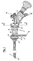
- the endoscope and shaft system shown as an embodiment consists essentially of two modules.
- the first assembly is formed by an access shaft 2 and a handle portion 4, which is detachably connected to the access shaft 2.
- the handle part 4 is known to be formed at its distal end with a receptacle for the proximal end of the access shaft 2 by means of a latching connection.
- the second assembly is formed from a connector 6 and an endoscope 8.
- the endoscope 8 is inserted from the proximal end into the connector 6 so that the optic shaft 10 of the endoscope extends distally into the access shaft 2.
- the endoscope 8 is detachably connected to the connecting piece 6, as will be described in more detail below.
- the access shaft 2 ends at its proximal end to a connecting piece 12. This is inserted into a distal-side receptacle 14 of the handle part 4 and there releasably connected via the locking elements 16 positively with the handle part 4.
- the handle part 4 An essential part of the handle part 4 is the handle 18, which extends radially outward. About the receptacle 14 and the connector 12, the handle is connected directly to the access shaft 2, so that manipulation forces can be transmitted directly to the access shaft 2 via the handle 18, without the endoscope 8 is loaded with these forces. In this way, relatively high manipulation forces can be applied to the access shaft 2.
- the handle part 4 at the proximal end of a cylindrical sleeve 20.
- This serves to connect to the connecting piece 6 and is inserted for this purpose from the distal end into the connecting piece 6.
- the handle part 4 and the connector 6 are thus simply plugged together and can be easily separated.
- the longitudinal axis X 1 of the cylindrical receptacle 14 and the longitudinal axis X 2 of the sleeve 20 by a dimension e offset parallel to each other, that is offset in the lateral direction.
- the offset e of the sleeve 20 relative to the receptacle 14 in the handle part 4 is related to the configuration of the access shaft 2.
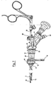
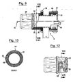
- the access shaft is shown in cross-section. It can be seen that the access shaft 2 has a substantially oval cross-section. That is, the extension or width B of the access shaft in a first cross-sectional direction is greater than the extension H in a second cross-sectional direction normal to the first cross-sectional direction.
- the optical shaft 10 is not arranged centrally but laterally offset in one half of the inner cross section of the access shaft 2.
- the longitudinal axis X E of the optical shaft 10 is offset parallel to the longitudinal or central axis Xz of the access shaft 2, which extends in extension of the longitudinal axis X 1 of the receptacle 14.
- a free lumen 22 remains in which a working instrument 24 can be used.
- This can be a pair of pliers, as in Fig. 7 is shown.
- the endoscope or optical shaft 10 and the working insert 24 optimally fill the inner cross section of the access shaft 2, while at the same time keeping the height H of the access shaft 2 low, so that the instrument can also be moved to the operating area via narrow access channels.
- the arrangement of the optical shaft 10 in the interior of the access shaft 2 in one half laterally offset with respect to the central axis Xz of the access shaft 2 is achieved by the offset e between the sleeve 20 and receptacle 14 in the handle part 4.
- the offset e ensures that the endoscope 8 remains rotatable about the longitudinal axis of the endoscope or optic shaft 10 in order to be able to rotate the field of view in the operating area.
- This rotation is achieved in that the connecting piece 6 on the sleeve 20 of the handle part 4 about the longitudinal axis X 2 of the sleeve 20 can be rotated.
- the endoscope 8 is positioned in the connecting piece 6 such that the longitudinal axis X E of the optical shaft 10 extends along the longitudinal axis X 2 of the connecting piece 6 and the sleeve 20.
- the connector 6 is, as best in the detail view of FIG. 9 can be seen, essentially of an inner sleeve 26 and an outer sleeve 28, which via threads 30 and 32 are engaged with each other.
- the thread 30 is formed as an external thread on the inner sleeve 26
- the thread 32 is formed as an internal thread on the inside of the outer sleeve 28.
- the inner sleeve 26 extends proximally out of the outer sleeve 28. There it is provided with a locking ring 34 on the outer circumference.
- the outer sleeve 28 is provided on the outer circumference with a collar 36 which projects radially outward.
- the inner sleeve 26 and the outer sleeve 28 can be grasped and rotated against each other. Through the threaded engagement they move in the axial direction apart or together, depending on the direction of rotation. In this way, an axial delivery by the dimension s is possible.
- the endoscope 8 is fixed, as will be explained in more detail below.
- the endoscope is also moved relative to the handle part 4 connected to the connecting piece 6 via the outer sleeve 28 and thus in the access shaft 2 in the axial direction. In this way, the distal end of the endoscope can also be moved by the dimension s by turning the two sleeves of the connecting piece 6.
- the inner sleeve 26 has at its proximal end a sector-shaped cut-out 38 which is open towards the proximal end.
- the extending in the longitudinal direction of the sleeve 26 and the cutout 38 bounding end faces of the sleeve 26 form two contact surfaces 40.
- the endoscope 8 has two projecting to opposite sides of shoulders 41, which extend parallel to the longitudinal direction X E of the endoscope. These shoulders 41 form contact surfaces 42, which are opposite to the contact surfaces 40 on the sleeve 26 and come to rest with them.
- the width of the endoscope 8 between the shoulders 41 is selected so that it corresponds to the width of the cutout 38.
- the endoscope 8 can be positively inserted into the cutout 38 in the sleeve.
- the endoscope 8 is located so that the endoscope shaft 10 extends centrally in the sleeve 26 in the direction of its longitudinal axis X 2 .
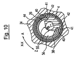
- the endoscope is fixed via a clamping ring 44, which surrounds the inner sleeve 26 on the outer circumference and is located in the interior of the annular locking ring 34.
- the clamping ring 44 is rotatable with the locking ring 34 about the sleeve 26 in the direction of the arrows A and Z.
- the rotation in the direction A causes a rotation in the open position, which in Fig. 10 is shown.
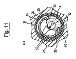
- the rotation in direction Z causes a rotation in the closed position, which in FIG. 11 is shown.
- the endoscope 8 is pressed against the contact surfaces 40 and clamped.
- the clamping ring 44 has a circumferentially changing diameter or radius on the inner circumference.
- a region of the clamping ring is located above the endoscope 8, which has a larger radius r 1 . This leaves a certain clearance between the clamping ring and the endoscope 8, so that it is not clamped.
- the area of the clamping ring 44 with a smaller inner radius r 2 comes to rest over the endoscope 8, as in FIG Fig. 11 shown so that the endoscope 8 is pressed with its contact surfaces 42 backlash against the contact surfaces 40 on the inner sleeve 26 and thus fixed to the sleeve 26 and thus in the connector 6.
- the endoscope 8 When the endoscope 8 is fixed in the connecting piece 6, it can be removed together with the connecting piece 6 from the grip part 4 and thus removed from the access shaft 2. This may be required if the entire internal cross section of the access shaft is needed, for example to remove larger amounts of tissue from the surgical field. Since in this removal of the endoscope 8 from the access shaft 2, the sleeves 26 and 28 of the connecting piece 6 are not rotated against each other, the positioning of the endoscope 8 is maintained in the axial direction. That is, when the endoscope 8 is again inserted into the access shaft 2 and the connecting piece 6 is connected to the grip part 4, the endoscope 8 is again in the same axial position as before the removal.
- the engagement of the connecting piece 6 and the handle part 4 takes place in such a way that the proximal-side sleeve 20 of the grip part 4 extends into the inner sleeve 26 of the connecting piece 6.
- the outer diameter of the sleeve 20 corresponds to the inner diameter of the inner sleeve 26.
- the outer sleeve 28 is provided at its distal end with a radially inwardly directed annular collar 46, which also comes to rest on the outer circumference of the sleeve 20.
- the outer sleeve 28 is provided in the region of the threaded engagement with the inner sleeve 26 with a spring element.
- the spring element is designed as a circumferentially extending tongue 48.
- the tongue 48 is thereby formed by a substantially U-shaped parting line 50 formed in the wall of the sleeve 28. This parting line 50 extends through the entire thickness of the wall of the sleeve 28 from the outer periphery to the inner periphery.
- the tongue 48 thus formed is provided at its free end with a radially outwardly projecting bead 52. As in Fig.
- the outer circumference of the sleeve 28 in the region in which the tongue 48 is formed substantially oval.
- the sleeve is circumferentially surrounded by a clamping ring 54.
- the bead 52 lies against the inner circumference of the clamping ring 54. This causes the tongue 48 to be pressed inwardly against the outer circumference of the inner sleeve 26. In this way, there is a clamping between the inner sleeve 26 and the outer sleeve 28, which eliminates the game from the engagement of the threads 30 and 32.
- the endoscope 8 is formed in the region with which it engages in the recess or the cutout 38 of the sleeve 26 in cross section roof edge, wherein the oblique outer sides 55 extend substantially tangentially to the outer periphery of the optical shaft 10.
- This embodiment of the endoscope in this area has the advantage that the endoscope covers in cross-section from the interior of the sleeve 26 only a sector smaller 180 degrees. The largest part of the cross section remains free and forms a free lumen 56. This covers the front side of the access shaft 2 in the region of the free lumen 22, which is provided for receiving the working instrument 24.
- the endoscope 8 is still rotated over a large angular range about its longitudinal axis X E by the sleeve 26 is rotated on the sleeve 20.
- the free lumen 56 of the sleeve 26 sweeps arcuately the area which is provided for receiving the working instrument 24.
- the free lumen 56 of the sleeve 26 and the free lumen 22 of the access shaft are in alignment and form a common free lumen from the proximal to the distal end. So can the endoscope 8 are rotated until the working tool 24 abuts one of the two inclined surfaces 55 of the roof edge profile of the endoscope 8.
- an endoscope and shaft system which on the one hand makes it possible to transmit large manipulation forces on the access shaft 2 and at the same time allows great mobility of the endoscope 8 in the interior of the access shaft 2.
- the endoscope 8 can be moved in the axial direction X E and rotated about its longitudinal axis X E. At the same time the endoscope 8 remains completely free of manipulation forces, which are transmitted from the handle 18 to the access shaft.
- the endoscope 8 is otherwise formed in a conventional manner, that is, it has an optical system, optical fibers for illumination and a flushing channel. For these, a flushing connection 58 and a light conductor connection 60 are provided on the proximal side.
- optical system may be a CCD element or the like, and instead of the light guide, one or more LED, as customary in a video endoscope, may be provided.
Landscapes
- Health & Medical Sciences (AREA)
- Life Sciences & Earth Sciences (AREA)
- Surgery (AREA)
- Engineering & Computer Science (AREA)
- Animal Behavior & Ethology (AREA)
- General Health & Medical Sciences (AREA)
- Biomedical Technology (AREA)
- Heart & Thoracic Surgery (AREA)
- Medical Informatics (AREA)
- Molecular Biology (AREA)
- Pathology (AREA)
- Nuclear Medicine, Radiotherapy & Molecular Imaging (AREA)
- Public Health (AREA)
- Veterinary Medicine (AREA)
- Mechanical Engineering (AREA)
- Physics & Mathematics (AREA)
- Biophysics (AREA)
- Optics & Photonics (AREA)
- Radiology & Medical Imaging (AREA)
- Endoscopes (AREA)
Applications Claiming Priority (1)
| Application Number | Priority Date | Filing Date | Title |
|---|---|---|---|
| DE102008029301A DE102008029301A1 (de) | 2008-06-19 | 2008-06-19 | Endoskop- und Schaftsystem |
Publications (2)
| Publication Number | Publication Date |
|---|---|
| EP2135542A1 EP2135542A1 (de) | 2009-12-23 |
| EP2135542B1 true EP2135542B1 (de) | 2012-09-05 |
Family
ID=41137854
Family Applications (1)
| Application Number | Title | Priority Date | Filing Date |
|---|---|---|---|
| EP09007594A Active EP2135542B1 (de) | 2008-06-19 | 2009-06-09 | Endoskop- und Schaftsystem |
Country Status (5)
| Country | Link |
|---|---|
| US (1) | US9597113B2 (ja) |
| EP (1) | EP2135542B1 (ja) |
| JP (1) | JP5043888B2 (ja) |
| DE (1) | DE102008029301A1 (ja) |
| ES (1) | ES2394401T3 (ja) |
Cited By (2)
| Publication number | Priority date | Publication date | Assignee | Title |
|---|---|---|---|---|
| USD736924S1 (en) | 2014-01-23 | 2015-08-18 | Karl Storz Gmbh & Co. Kg | Trocar |
| DE102022202486B3 (de) | 2022-03-14 | 2023-08-24 | Richard Wolf Gmbh | Zielgerät zur gezielten Führung einer Hohlnadel bei einem endoskopisch-chirurgischen Eingriff |
Families Citing this family (14)
| Publication number | Priority date | Publication date | Assignee | Title |
|---|---|---|---|---|
| DE102012220651B4 (de) * | 2012-11-13 | 2016-10-06 | Richard Wolf Gmbh | Endoskop-Zwischenstück |
| AU2015221258B2 (en) | 2014-02-21 | 2019-11-21 | Cilag Gmbh International | A set comprising a surgical instrument |
| CN103948365A (zh) * | 2014-05-13 | 2014-07-30 | 黎庆初 | 一种新型脊柱内窥镜工作通道系统 |
| CN104013381A (zh) * | 2014-05-29 | 2014-09-03 | 中山大学附属第三医院 | 三维椎间盘镜 |
| US11020144B2 (en) | 2015-07-21 | 2021-06-01 | 3Dintegrated Aps | Minimally invasive surgery system |
| WO2017012624A1 (en) | 2015-07-21 | 2017-01-26 | 3Dintegrated Aps | Cannula assembly kit, trocar assembly kit, sleeve assembly, minimally invasive surgery system and method therefor |
| DK178899B1 (en) | 2015-10-09 | 2017-05-08 | 3Dintegrated Aps | A depiction system |
| CN106618448B (zh) * | 2016-11-02 | 2018-09-28 | 张立军 | 一种内窥镜紧固及调节装置 |
| DE102017108272A1 (de) * | 2017-04-19 | 2018-10-25 | Carl Zeiss Meditec Ag | Endoskopische Sonde |
| WO2019172926A1 (en) * | 2018-03-09 | 2019-09-12 | Nido Surgical, Inc. | Instrument port including optical bulb secured to port body |
| US11324555B2 (en) | 2018-03-09 | 2022-05-10 | The Children's Medical Center Corporation | Instrument port including optical bulb secured to port body |
| CN108742475A (zh) * | 2018-07-17 | 2018-11-06 | 南京微来医学科技有限公司 | 手持式电子宫腔镜 |
| DE102022203780A1 (de) | 2022-04-14 | 2023-10-19 | Richard Wolf Gmbh | Endoskopisches Instrument |
| CN115998223A (zh) * | 2023-01-31 | 2023-04-25 | 湖南省华芯医疗器械有限公司 | 一种内窥镜插入部用连接器及插入部的固定结构 |
Family Cites Families (19)
| Publication number | Priority date | Publication date | Assignee | Title |
|---|---|---|---|---|
| JPS5881029A (ja) | 1981-11-06 | 1983-05-16 | オリンパス光学工業株式会社 | レゼクトスコ−プ |
| GB2130889B (en) * | 1982-11-26 | 1986-06-18 | Wolf Gmbh Richard | Rectoscope |
| DE3319049A1 (de) * | 1982-11-26 | 1984-05-30 | Richard Wolf Gmbh, 7134 Knittlingen | Rektoskop |
| JP2664245B2 (ja) | 1989-05-12 | 1997-10-15 | オリンパス光学工業株式会社 | 硬性内視鏡装置 |
| DE4014350A1 (de) | 1990-05-04 | 1991-11-14 | Wolf Gmbh Richard | Koagulationsinstrument zum stillen von blutungen in nasenhoehlen |
| DE4417637A1 (de) * | 1994-05-19 | 1995-11-23 | Rudolf Dr Med Bertagnoli | Instrument zur perkutanen Behandlung von Gewebeteilen |
| DE4425705C2 (de) * | 1994-07-01 | 2002-08-01 | Storz Karl Gmbh & Co Kg | Endoskopisches Instrument |
| DE4444049A1 (de) * | 1994-12-10 | 1996-06-20 | Wolf Gmbh Richard | Vorrichtung für die Verbindung eines Endoskops mit einem Zusatzgerät |
| JP3665420B2 (ja) * | 1996-06-05 | 2005-06-29 | ペンタックス株式会社 | 内視鏡用案内装置 |
| TW375522B (en) * | 1996-10-24 | 1999-12-01 | Danek Medical Inc | Devices for percutaneous surgery under direct visualization and through an elongated cannula |
| JP3429685B2 (ja) * | 1997-10-06 | 2003-07-22 | オリンパス光学工業株式会社 | 内視鏡案内管 |
| US6196967B1 (en) * | 1998-03-18 | 2001-03-06 | Linvatec Corporation | Arthroscopic component joining system |
| DE19935725C2 (de) * | 1999-07-29 | 2003-11-13 | Wolf Gmbh Richard | Medizinisches Instrument, insbesondere Rektoskop |
| DE10310614B4 (de) * | 2002-03-25 | 2007-10-11 | Richard Wolf Gmbh | Resektoskop |
| DE202004014828U1 (de) * | 2004-09-21 | 2004-12-02 | Richard Wolf Gmbh | Endoskopisches Instrument |
| DE502005010766D1 (de) * | 2005-11-16 | 2011-02-10 | Wolf Gmbh Richard | Optisches Instrument |
| US20080208001A1 (en) * | 2007-02-26 | 2008-08-28 | Ron Hadani | Conforming endoscope |
| DE102007032201B4 (de) * | 2007-07-11 | 2013-08-14 | Schölly Fiberoptic GmbH | Endoskop |
| US20090054728A1 (en) * | 2007-08-21 | 2009-02-26 | Trusty Robert M | Manipulatable guide system and methods for natural orifice translumenal endoscopic surgery |
-
2008
- 2008-06-19 DE DE102008029301A patent/DE102008029301A1/de not_active Withdrawn
-
2009
- 2009-06-09 EP EP09007594A patent/EP2135542B1/de active Active
- 2009-06-09 ES ES09007594T patent/ES2394401T3/es active Active
- 2009-06-19 JP JP2009147015A patent/JP5043888B2/ja active Active
- 2009-06-19 US US12/488,003 patent/US9597113B2/en active Active
Cited By (3)
| Publication number | Priority date | Publication date | Assignee | Title |
|---|---|---|---|---|
| USD736924S1 (en) | 2014-01-23 | 2015-08-18 | Karl Storz Gmbh & Co. Kg | Trocar |
| DE102022202486B3 (de) | 2022-03-14 | 2023-08-24 | Richard Wolf Gmbh | Zielgerät zur gezielten Führung einer Hohlnadel bei einem endoskopisch-chirurgischen Eingriff |
| WO2023174493A1 (de) | 2022-03-14 | 2023-09-21 | Richard Wolf Gmbh | Zielgerät zur gezielten führung einer hohlnadel bei einem endoskopisch-chirurgischen eingriff |
Also Published As
| Publication number | Publication date |
|---|---|
| JP2010000361A (ja) | 2010-01-07 |
| US9597113B2 (en) | 2017-03-21 |
| JP5043888B2 (ja) | 2012-10-10 |
| EP2135542A1 (de) | 2009-12-23 |
| US20090318763A1 (en) | 2009-12-24 |
| DE102008029301A1 (de) | 2009-12-24 |
| ES2394401T3 (es) | 2013-01-31 |
Similar Documents
| Publication | Publication Date | Title |
|---|---|---|
| EP2135542B1 (de) | Endoskop- und Schaftsystem | |
| EP0860148B1 (de) | Bajonettkupplung zum lösbaren Verbinden zweier Rohrschaftinstrumente oder -instrumententeile | |
| EP2962651B1 (de) | Medizinischer schraubendreher und schaft für den medizinischen schraubendreher | |
| EP0925028B1 (de) | Zerlegbares medizinisches instrument mit selbstorientierender kupplung | |
| EP1523932B1 (de) | Endoskop | |
| DE10357105B3 (de) | Medizinisches Instrument | |
| EP1779792A1 (de) | Facettengelenkfräser | |
| DE102016108504A1 (de) | Medizintechnisches Instrument zur provisorischen Fixierung einer polyaxialen Pedikelschraube | |
| DE102005032197B4 (de) | Endoskopisches Instrument | |
| EP1297790A1 (de) | Chirurgisches Zielgerät | |
| EP3351191B1 (de) | Chirurgisches instrument, insbesondere für die neurochirurgie | |
| EP2581031A1 (de) | Abwinkelungsvorrichtung | |
| EP3737987B1 (de) | Videoendoskop | |
| EP3744270B1 (de) | System zur positionierung | |
| DE19901389B4 (de) | Endoskopisches Behandlungssystem | |
| EP1637065A1 (de) | Endoskopisches Instrument | |
| DE102005050031A1 (de) | Chirurgisches Instrument zum Entfernen eines Zwischenwirbelimplantats | |
| EP2853212B1 (de) | Chirurgisches Instrument | |
| EP3968836B1 (de) | Gewebeclip-applikations-ausrüst- oder nachrüstsatz | |
| EP3574864B1 (de) | Selbstsichernde kupplungsvorrichtung | |
| DE10333956B4 (de) | Sichtobturator | |
| WO2023194131A1 (de) | Medizinisches werkzeugsystem | |
| DE4425705A1 (de) | Endoskopisches Instrument | |
| EP1303219B1 (de) | Medizinisches instrument, insbesondere resektoskop | |
| DE202007000427U1 (de) | Chirurgischer Haltegriff und chirurgisches Instrument |
Legal Events
| Date | Code | Title | Description |
|---|---|---|---|
| PUAI | Public reference made under article 153(3) epc to a published international application that has entered the european phase |
Free format text: ORIGINAL CODE: 0009012 |
|
| AK | Designated contracting states |
Kind code of ref document: A1 Designated state(s): AT BE BG CH CY CZ DE DK EE ES FI FR GB GR HR HU IE IS IT LI LT LU LV MC MK MT NL NO PL PT RO SE SI SK TR |
|
| 17P | Request for examination filed |
Effective date: 20100324 |
|
| 17Q | First examination report despatched |
Effective date: 20100414 |
|
| GRAP | Despatch of communication of intention to grant a patent |
Free format text: ORIGINAL CODE: EPIDOSNIGR1 |
|
| GRAC | Information related to communication of intention to grant a patent modified |
Free format text: ORIGINAL CODE: EPIDOSCIGR1 |
|
| GRAS | Grant fee paid |
Free format text: ORIGINAL CODE: EPIDOSNIGR3 |
|
| GRAJ | Information related to disapproval of communication of intention to grant by the applicant or resumption of examination proceedings by the epo deleted |
Free format text: ORIGINAL CODE: EPIDOSDIGR1 |
|
| GRAL | Information related to payment of fee for publishing/printing deleted |
Free format text: ORIGINAL CODE: EPIDOSDIGR3 |
|
| GRAS | Grant fee paid |
Free format text: ORIGINAL CODE: EPIDOSNIGR3 |
|
| GRAP | Despatch of communication of intention to grant a patent |
Free format text: ORIGINAL CODE: EPIDOSNIGR1 |
|
| GRAA | (expected) grant |
Free format text: ORIGINAL CODE: 0009210 |
|
| AK | Designated contracting states |
Kind code of ref document: B1 Designated state(s): AT BE BG CH CY CZ DE DK EE ES FI FR GB GR HR HU IE IS IT LI LT LU LV MC MK MT NL NO PL PT RO SE SI SK TR |
|
| REG | Reference to a national code |
Ref country code: GB Ref legal event code: FG4D Free format text: NOT ENGLISH |
|
| REG | Reference to a national code |
Ref country code: CH Ref legal event code: EP |
|
| REG | Reference to a national code |
Ref country code: AT Ref legal event code: REF Ref document number: 573707 Country of ref document: AT Kind code of ref document: T Effective date: 20120915 |
|
| REG | Reference to a national code |
Ref country code: IE Ref legal event code: FG4D Free format text: LANGUAGE OF EP DOCUMENT: GERMAN |
|
| REG | Reference to a national code |
Ref country code: DE Ref legal event code: R096 Ref document number: 502009004587 Country of ref document: DE Effective date: 20121031 |
|
| REG | Reference to a national code |
Ref country code: CH Ref legal event code: NV Representative=s name: ISLER AND PEDRAZZINI AG, CH |
|
| REG | Reference to a national code |
Ref country code: NL Ref legal event code: VDEP Effective date: 20120905 |
|
| PG25 | Lapsed in a contracting state [announced via postgrant information from national office to epo] |
Ref country code: HR Free format text: LAPSE BECAUSE OF FAILURE TO SUBMIT A TRANSLATION OF THE DESCRIPTION OR TO PAY THE FEE WITHIN THE PRESCRIBED TIME-LIMIT Effective date: 20120905 Ref country code: FI Free format text: LAPSE BECAUSE OF FAILURE TO SUBMIT A TRANSLATION OF THE DESCRIPTION OR TO PAY THE FEE WITHIN THE PRESCRIBED TIME-LIMIT Effective date: 20120905 Ref country code: CY Free format text: LAPSE BECAUSE OF FAILURE TO SUBMIT A TRANSLATION OF THE DESCRIPTION OR TO PAY THE FEE WITHIN THE PRESCRIBED TIME-LIMIT Effective date: 20120905 Ref country code: LT Free format text: LAPSE BECAUSE OF FAILURE TO SUBMIT A TRANSLATION OF THE DESCRIPTION OR TO PAY THE FEE WITHIN THE PRESCRIBED TIME-LIMIT Effective date: 20120905 Ref country code: NO Free format text: LAPSE BECAUSE OF FAILURE TO SUBMIT A TRANSLATION OF THE DESCRIPTION OR TO PAY THE FEE WITHIN THE PRESCRIBED TIME-LIMIT Effective date: 20121205 |
|
| REG | Reference to a national code |
Ref country code: ES Ref legal event code: FG2A Ref document number: 2394401 Country of ref document: ES Kind code of ref document: T3 Effective date: 20130131 |
|
| REG | Reference to a national code |
Ref country code: LT Ref legal event code: MG4D Effective date: 20120905 |
|
| PG25 | Lapsed in a contracting state [announced via postgrant information from national office to epo] |
Ref country code: GR Free format text: LAPSE BECAUSE OF FAILURE TO SUBMIT A TRANSLATION OF THE DESCRIPTION OR TO PAY THE FEE WITHIN THE PRESCRIBED TIME-LIMIT Effective date: 20121206 Ref country code: LV Free format text: LAPSE BECAUSE OF FAILURE TO SUBMIT A TRANSLATION OF THE DESCRIPTION OR TO PAY THE FEE WITHIN THE PRESCRIBED TIME-LIMIT Effective date: 20120905 Ref country code: SE Free format text: LAPSE BECAUSE OF FAILURE TO SUBMIT A TRANSLATION OF THE DESCRIPTION OR TO PAY THE FEE WITHIN THE PRESCRIBED TIME-LIMIT Effective date: 20120905 Ref country code: SI Free format text: LAPSE BECAUSE OF FAILURE TO SUBMIT A TRANSLATION OF THE DESCRIPTION OR TO PAY THE FEE WITHIN THE PRESCRIBED TIME-LIMIT Effective date: 20120905 |
|
| PG25 | Lapsed in a contracting state [announced via postgrant information from national office to epo] |
Ref country code: RO Free format text: LAPSE BECAUSE OF FAILURE TO SUBMIT A TRANSLATION OF THE DESCRIPTION OR TO PAY THE FEE WITHIN THE PRESCRIBED TIME-LIMIT Effective date: 20120905 Ref country code: CZ Free format text: LAPSE BECAUSE OF FAILURE TO SUBMIT A TRANSLATION OF THE DESCRIPTION OR TO PAY THE FEE WITHIN THE PRESCRIBED TIME-LIMIT Effective date: 20120905 Ref country code: NL Free format text: LAPSE BECAUSE OF FAILURE TO SUBMIT A TRANSLATION OF THE DESCRIPTION OR TO PAY THE FEE WITHIN THE PRESCRIBED TIME-LIMIT Effective date: 20120905 Ref country code: EE Free format text: LAPSE BECAUSE OF FAILURE TO SUBMIT A TRANSLATION OF THE DESCRIPTION OR TO PAY THE FEE WITHIN THE PRESCRIBED TIME-LIMIT Effective date: 20120905 Ref country code: IS Free format text: LAPSE BECAUSE OF FAILURE TO SUBMIT A TRANSLATION OF THE DESCRIPTION OR TO PAY THE FEE WITHIN THE PRESCRIBED TIME-LIMIT Effective date: 20130105 |
|
| PG25 | Lapsed in a contracting state [announced via postgrant information from national office to epo] |
Ref country code: SK Free format text: LAPSE BECAUSE OF FAILURE TO SUBMIT A TRANSLATION OF THE DESCRIPTION OR TO PAY THE FEE WITHIN THE PRESCRIBED TIME-LIMIT Effective date: 20120905 Ref country code: PT Free format text: LAPSE BECAUSE OF FAILURE TO SUBMIT A TRANSLATION OF THE DESCRIPTION OR TO PAY THE FEE WITHIN THE PRESCRIBED TIME-LIMIT Effective date: 20130107 Ref country code: PL Free format text: LAPSE BECAUSE OF FAILURE TO SUBMIT A TRANSLATION OF THE DESCRIPTION OR TO PAY THE FEE WITHIN THE PRESCRIBED TIME-LIMIT Effective date: 20120905 |
|
| PLBI | Opposition filed |
Free format text: ORIGINAL CODE: 0009260 |
|
| PLAX | Notice of opposition and request to file observation + time limit sent |
Free format text: ORIGINAL CODE: EPIDOSNOBS2 |
|
| 26 | Opposition filed |
Opponent name: KARL STORZ GMBH & CO. KG Effective date: 20130529 |
|
| PG25 | Lapsed in a contracting state [announced via postgrant information from national office to epo] |
Ref country code: DK Free format text: LAPSE BECAUSE OF FAILURE TO SUBMIT A TRANSLATION OF THE DESCRIPTION OR TO PAY THE FEE WITHIN THE PRESCRIBED TIME-LIMIT Effective date: 20120905 Ref country code: BG Free format text: LAPSE BECAUSE OF FAILURE TO SUBMIT A TRANSLATION OF THE DESCRIPTION OR TO PAY THE FEE WITHIN THE PRESCRIBED TIME-LIMIT Effective date: 20121205 |
|
| REG | Reference to a national code |
Ref country code: DE Ref legal event code: R026 Ref document number: 502009004587 Country of ref document: DE Effective date: 20130529 |
|
| PLBB | Reply of patent proprietor to notice(s) of opposition received |
Free format text: ORIGINAL CODE: EPIDOSNOBS3 |
|
| BERE | Be: lapsed |
Owner name: RICHARD WOLF G.M.B.H. Effective date: 20130630 |
|
| PG25 | Lapsed in a contracting state [announced via postgrant information from national office to epo] |
Ref country code: MC Free format text: LAPSE BECAUSE OF FAILURE TO SUBMIT A TRANSLATION OF THE DESCRIPTION OR TO PAY THE FEE WITHIN THE PRESCRIBED TIME-LIMIT Effective date: 20120905 |
|
| REG | Reference to a national code |
Ref country code: IE Ref legal event code: MM4A |
|
| PG25 | Lapsed in a contracting state [announced via postgrant information from national office to epo] |
Ref country code: BE Free format text: LAPSE BECAUSE OF NON-PAYMENT OF DUE FEES Effective date: 20130630 |
|
| PG25 | Lapsed in a contracting state [announced via postgrant information from national office to epo] |
Ref country code: IE Free format text: LAPSE BECAUSE OF NON-PAYMENT OF DUE FEES Effective date: 20130609 |
|
| PG25 | Lapsed in a contracting state [announced via postgrant information from national office to epo] |
Ref country code: MT Free format text: LAPSE BECAUSE OF FAILURE TO SUBMIT A TRANSLATION OF THE DESCRIPTION OR TO PAY THE FEE WITHIN THE PRESCRIBED TIME-LIMIT Effective date: 20120905 |
|
| PLCK | Communication despatched that opposition was rejected |
Free format text: ORIGINAL CODE: EPIDOSNREJ1 |
|
| PG25 | Lapsed in a contracting state [announced via postgrant information from national office to epo] |
Ref country code: TR Free format text: LAPSE BECAUSE OF FAILURE TO SUBMIT A TRANSLATION OF THE DESCRIPTION OR TO PAY THE FEE WITHIN THE PRESCRIBED TIME-LIMIT Effective date: 20120905 |
|
| APAH | Appeal reference modified |
Free format text: ORIGINAL CODE: EPIDOSCREFNO |
|
| APBM | Appeal reference recorded |
Free format text: ORIGINAL CODE: EPIDOSNREFNO |
|
| APBP | Date of receipt of notice of appeal recorded |
Free format text: ORIGINAL CODE: EPIDOSNNOA2O |
|
| PG25 | Lapsed in a contracting state [announced via postgrant information from national office to epo] |
Ref country code: LU Free format text: LAPSE BECAUSE OF NON-PAYMENT OF DUE FEES Effective date: 20130609 Ref country code: MK Free format text: LAPSE BECAUSE OF FAILURE TO SUBMIT A TRANSLATION OF THE DESCRIPTION OR TO PAY THE FEE WITHIN THE PRESCRIBED TIME-LIMIT Effective date: 20120905 Ref country code: HU Free format text: LAPSE BECAUSE OF FAILURE TO SUBMIT A TRANSLATION OF THE DESCRIPTION OR TO PAY THE FEE WITHIN THE PRESCRIBED TIME-LIMIT; INVALID AB INITIO Effective date: 20090609 |
|
| REG | Reference to a national code |
Ref country code: AT Ref legal event code: MM01 Ref document number: 573707 Country of ref document: AT Kind code of ref document: T Effective date: 20140609 |
|
| APBQ | Date of receipt of statement of grounds of appeal recorded |
Free format text: ORIGINAL CODE: EPIDOSNNOA3O |
|
| PG25 | Lapsed in a contracting state [announced via postgrant information from national office to epo] |
Ref country code: AT Free format text: LAPSE BECAUSE OF NON-PAYMENT OF DUE FEES Effective date: 20140609 |
|
| REG | Reference to a national code |
Ref country code: FR Ref legal event code: PLFP Year of fee payment: 8 |
|
| REG | Reference to a national code |
Ref country code: FR Ref legal event code: PLFP Year of fee payment: 9 |
|
| PLAB | Opposition data, opponent's data or that of the opponent's representative modified |
Free format text: ORIGINAL CODE: 0009299OPPO |
|
| R26 | Opposition filed (corrected) |
Opponent name: KARL STORZ SE & CO. KG Effective date: 20130529 |
|
| REG | Reference to a national code |
Ref country code: FR Ref legal event code: PLFP Year of fee payment: 10 |
|
| APAH | Appeal reference modified |
Free format text: ORIGINAL CODE: EPIDOSCREFNO |
|
| REG | Reference to a national code |
Ref country code: DE Ref legal event code: R100 Ref document number: 502009004587 Country of ref document: DE |
|
| APBU | Appeal procedure closed |
Free format text: ORIGINAL CODE: EPIDOSNNOA9O |
|
| PLBN | Opposition rejected |
Free format text: ORIGINAL CODE: 0009273 |
|
| STAA | Information on the status of an ep patent application or granted ep patent |
Free format text: STATUS: OPPOSITION REJECTED |
|
| 27O | Opposition rejected |
Effective date: 20200224 |
|
| PGFP | Annual fee paid to national office [announced via postgrant information from national office to epo] |
Ref country code: FR Payment date: 20230622 Year of fee payment: 15 |
|
| PGFP | Annual fee paid to national office [announced via postgrant information from national office to epo] |
Ref country code: IT Payment date: 20230630 Year of fee payment: 15 Ref country code: GB Payment date: 20230622 Year of fee payment: 15 Ref country code: ES Payment date: 20230719 Year of fee payment: 15 Ref country code: CH Payment date: 20230702 Year of fee payment: 15 |
|
| PGFP | Annual fee paid to national office [announced via postgrant information from national office to epo] |
Ref country code: DE Payment date: 20240620 Year of fee payment: 16 |