EP2135542B1 - Endoskop- und Schaftsystem - Google Patents
Endoskop- und Schaftsystem Download PDFInfo
- Publication number
- EP2135542B1 EP2135542B1 EP09007594A EP09007594A EP2135542B1 EP 2135542 B1 EP2135542 B1 EP 2135542B1 EP 09007594 A EP09007594 A EP 09007594A EP 09007594 A EP09007594 A EP 09007594A EP 2135542 B1 EP2135542 B1 EP 2135542B1
- Authority
- EP
- European Patent Office
- Prior art keywords
- endoscope
- shank
- sleeve
- access
- connection piece
- Prior art date
- Legal status (The legal status is an assumption and is not a legal conclusion. Google has not performed a legal analysis and makes no representation as to the accuracy of the status listed.)
- Active
Links
Images


Classifications
-
- A—HUMAN NECESSITIES
- A61—MEDICAL OR VETERINARY SCIENCE; HYGIENE
- A61B—DIAGNOSIS; SURGERY; IDENTIFICATION
- A61B17/00—Surgical instruments, devices or methods, e.g. tourniquets
- A61B17/34—Trocars; Puncturing needles
- A61B17/3417—Details of tips or shafts, e.g. grooves, expandable, bendable; Multiple coaxial sliding cannulas, e.g. for dilating
- A61B17/3421—Cannulas
-
- A—HUMAN NECESSITIES
- A61—MEDICAL OR VETERINARY SCIENCE; HYGIENE
- A61B—DIAGNOSIS; SURGERY; IDENTIFICATION
- A61B1/00—Instruments for performing medical examinations of the interior of cavities or tubes of the body by visual or photographical inspection, e.g. endoscopes; Illuminating arrangements therefor
- A61B1/00112—Connection or coupling means
- A61B1/00121—Connectors, fasteners and adapters, e.g. on the endoscope handle
- A61B1/00128—Connectors, fasteners and adapters, e.g. on the endoscope handle mechanical, e.g. for tubes or pipes
-
- A—HUMAN NECESSITIES
- A61—MEDICAL OR VETERINARY SCIENCE; HYGIENE
- A61B—DIAGNOSIS; SURGERY; IDENTIFICATION
- A61B17/00—Surgical instruments, devices or methods, e.g. tourniquets
- A61B17/00234—Surgical instruments, devices or methods, e.g. tourniquets for minimally invasive surgery
- A61B2017/00238—Type of minimally invasive operation
- A61B2017/00261—Discectomy
-
- A—HUMAN NECESSITIES
- A61—MEDICAL OR VETERINARY SCIENCE; HYGIENE
- A61B—DIAGNOSIS; SURGERY; IDENTIFICATION
- A61B17/00—Surgical instruments, devices or methods, e.g. tourniquets
- A61B17/34—Trocars; Puncturing needles
- A61B17/3403—Needle locating or guiding means
- A61B2017/3405—Needle locating or guiding means using mechanical guide means
- A61B2017/3409—Needle locating or guiding means using mechanical guide means including needle or instrument drives
-
- A—HUMAN NECESSITIES
- A61—MEDICAL OR VETERINARY SCIENCE; HYGIENE
- A61B—DIAGNOSIS; SURGERY; IDENTIFICATION
- A61B17/00—Surgical instruments, devices or methods, e.g. tourniquets
- A61B17/34—Trocars; Puncturing needles
- A61B17/3417—Details of tips or shafts, e.g. grooves, expandable, bendable; Multiple coaxial sliding cannulas, e.g. for dilating
- A61B17/3421—Cannulas
- A61B2017/3445—Cannulas used as instrument channel for multiple instruments
-
- A—HUMAN NECESSITIES
- A61—MEDICAL OR VETERINARY SCIENCE; HYGIENE
- A61B—DIAGNOSIS; SURGERY; IDENTIFICATION
- A61B90/00—Instruments, implements or accessories specially adapted for surgery or diagnosis and not covered by any of the groups A61B1/00 - A61B50/00, e.g. for luxation treatment or for protecting wound edges
- A61B90/50—Supports for surgical instruments, e.g. articulated arms
Definitions
- the invention relates to an endoscope and shaft system for use in endoscopic spinal surgery, especially in the cervical spine.
- EP 0 455 188 A2 represents the closest prior art and discloses a coagulation instrument for nourishing bleeding in nasal cavities.
- This instrument has an access shaft, at the proximal end of a clutch housing is formed, in which a receptacle biased by a spring is held so that it is rotatable about its longitudinal axis in certain steps and to a certain extent against the spring bias axially displaceable.
- an endoscope optic is fixed by means of a clamping ring.
- This embodiment has the disadvantage that the removal of the endoscope optics releases on the one hand only a limited cross-section of the working channel and on the other hand the positioning of the endoscope is lost by loosening the clamping ring, so that the endoscope must be repositioned after reinserting into the instrument, especially in the axial direction ,
- the endoscope and shaft system according to the invention has an access shaft and an endoscope which can be inserted into the access shaft.
- the access shaft according to the invention has a handle part at its proximal end. This has the advantage that over the handle part manipulation forces can be transferred directly to the access shaft to position it in the operational area.
- the inserted endoscope remains free from the manipulation forces and is protected against damage. In this way, comparatively large manipulation forces can be transmitted without the endoscope having to be specially reinforced for this purpose.
- the endoscope can thus continue to be designed very slim adapted to the available small access channel, so that the available space can be optimally utilized.
- the endoscope is held by a connector.
- the endoscope is preferably detachably connected to the connecting piece.
- the connector in turn is detachably connected to the handle part or connectable.
- the connector may be disconnected from the handle and access shank together with the endoscope, for example to guide other instruments through the access shaft into the surgical field.
- the handling of the access shaft can be done solely on the directly connected to the access shaft handle.
- the connector when connected to the handle member, is rotatable about the longitudinal axis of the endoscope relative to the handle member. In this way, the endoscope can be rotated in the access shaft about its longitudinal axis, in order to be able to observe as large a region of the surgical field as possible with the endoscope.
- the endoscope is not only rotatable but also axially movable.
- Such axial mobility can be achieved, for example, by virtue of the fact that the connecting piece is not only rotatable relative to the grip part but also axially movable relative to the grip part.
- the endoscope is then moved axially together with the connecting piece and / or rotated to the distal End of the endoscope to place so that a desired area of the operating area can be considered.
- an endoscope and shaft system is thus created, which on the one hand enables the transmission of relatively large manipulation forces and on the other hand at the same time allows a, preferably free, mobility of the endoscope in the access shaft.
- the handle part and / or the connecting piece are designed such that the endoscope held in the connecting piece is arranged with its longitudinal axis offset parallel to the longitudinal axis of the access shaft.
- a free lumen is created in addition to the endoscope in the cross section of the access shaft, through which a working instrument can be guided through the access shaft to the operating area in addition to the endoscope.
- the access shaft has a cross-sectional shape which has a larger width in a first direction than in a second direction which is normal to the first direction. That is, the access shaft is not circular in cross section but substantially oval. This makes it possible to form the access shaft in cross section with the lowest possible height, so that it can be fed well into the area of the spinal column, in particular in the intervertebral space. At the same time a larger enough lumen in the interior of the access shaft is created by the larger cross-section width through which an endoscope and possibly other instruments can be supplied.
- the endoscope is preferably placed so that its longitudinal or central axis is offset parallel to the longitudinal or central axis of the access shaft. That is ideally located in the oval cross-section of the access shaft endoscope in one half and the other half forms a free lumen, by which, for example, a working instrument can be supplied.
- the access shaft is detachably connected to the handle part. This makes it possible to combine the instrument during insertion into the intervertebral space with other instruments and to disassemble for cleaning or maintenance purposes or, for example, to connect different access shafts with one and the same handle part. More preferably, the connection between the handle part and the access shaft is designed so that the access shaft can be connected in two possible angular positions with the handle part. That is, the access shaft can be rotated 180 degrees about its longitudinal axis in a second possible position with the handle portion. This allows for oval configuration of the access shaft and staggered arrangement of the endoscope to position the endoscope either in the two possible positions in Accessschaft.
- the connection between the handle part and access shaft is designed, for example, as a releasable ball detent connection.
- the handle portion has at its distal end a receptacle for the proximal end of the access shaft and has at its proximal end a receptacle for the connector, wherein these two receptacles are arranged offset parallel to each other in a direction transverse to the longitudinal axis of the access shaft.
- the handle provides for the staggered arrangement of endoscope and access shaft.
- the connector is positioned in the direction transverse to the longitudinal axis of the access shaft defined by the handle member.
- the rotatability of the endoscope about its longitudinal axis and preferably also an axial mobility of the endoscope in the access shaft remains ensured.
- the handle part and the connecting piece are detachably plugged together in the axial direction.
- This allows the connector to be easily removed from the handle portion to, for example, remove the endoscope connected to the connector from the access shaft. This may be necessary if the entire cross section of the access shaft is needed to remove larger amounts of tissue from the surgical field.
- the fact that the endoscope remains connected to the connector it is possible that the removal of the endoscope, the positioning of the endoscope is not lost. That is, when the connector is again plugged together with the handle portion, the endoscope is again in the same position as before the removal. This is ensured by positioning the endoscope over the connector, i. H. the connector has a positioning means for positioning the endoscope in the access shaft. This can include positioning in the axial direction and / or positioning with respect to the angular position of the endoscope about its longitudinal axis.
- the handle part preferably has at the proximal end a sleeve which engages from the distal end into the interior of the connecting piece. That is, the connector has at its distal end an opening which is adapted in size and cross-sectional shape of the shape and size of the outer periphery of the sleeve on the handle portion.
- the sleeve is circular cylindrical and the opening on the connecting piece is correspondingly cylindrical.
- the rotatability of the endoscope about its longitudinal axis is preferably achieved in that the sleeve of the handle part in the interior of the distal side Opening of the connector can rotate. That is, the connector rotates, preferably freely, on the sleeve on the handle portion.
- the connector has at its proximal end a mounting receptacle for releasably securing the endoscope. Through this attachment receptacle, the endoscope is defined and held on the connector. It is preferred that the endoscope for cleaning and maintenance purposes can be solved by the connector. Furthermore, this makes it possible that different endoscopes can be attached to one and the same connector.
- the detachable fastening of the endoscope is preferably possible in that the endoscope is releasably fixable by at least one contact surface of the fastening receptacle by means of a rotatable clamping ring with an inner diameter which changes over the circumference.
- the clamping ring is designed so that it is positioned in a released position so that a greater distance between the clamping ring and abutment surface is given, so that the endoscope is movable between the two. By turning the clamping ring, an area with a smaller inner diameter is brought to cover with the contact surface.
- the attachment receptacle is further preferably designed such that in addition to this non-positive clamping, a positive positioning of the endoscope is also provided in order to hold the endoscope in a defined position.
- the attachment receptacle is preferably formed by a sleeve which has a sector-shaped cut-out at the proximal end, wherein the end faces of the sleeve facing the cut-out bear contact surfaces form for the endoscope.
- the endoscope has a corresponding attachment portion, which can be inserted into this sector-shaped cutout.
- contact surfaces which are formed on the endoscope, on the contact surfaces of the recess, ie the end faces of the cutout of the sleeve to the plant. If a clamping ring, as has been described above, is provided by twisting the clamping ring preferably the endoscope is pressed with its contact surfaces against these end faces of the sleeve and so fixed to the sleeve.
- the connecting piece has an adjusting device, by means of which the endoscope is axially movable relative to the handle part. That is, via the connector is an axial positioning of the endoscope in the access shaft possible.
- the arrangement of the adjusting device on the connecting piece has the advantage that when the connecting piece is separated from the handle part, the setting of the adjusting device thereof is independent or is not affected, so that when the connecting piece is reconnected to the handle part, the previous positioning of the endoscope is restored in the access shaft.
- the connecting piece further preferably has two interengaging sleeves, which are engaged with each other via a thread, wherein a collar is arranged to rotate on a first sleeve and thus axial displacement of the first sleeve relative to the second sleeve.
- the endoscope is preferably attached in the manner described above.
- the adjusting ring is preferably attached to the other sleeve.
- a locking ring is preferably provided in order to fix the endoscope.
- the sleeve with the adjusting ring is further preferably attached to a sleeve formed at the proximal end of the handle part, as described above.
- the sleeve can be rotated with the adjusting ring on the sleeve of the handle part to rotate the endoscope about its longitudinal axis.
- the sleeve on the handle part further preferably extends so far into the interior of the connecting piece that it also engages in the second sleeve, which is in engagement with the sleeve with the adjusting ring via the thread.
- the outer of the two threaded sleeves further preferably has at its axial end facing away from the thread on a radially inwardly extending collar, which has an inner diameter substantially as the inner of the two threaded sleeves. This ensures that both threaded sleeves can come to rest on the outer circumference of the sleeve of the handle part. This ensures improved guidance and positioning of the connector on the handle.
- a spring element is arranged, which causes a clamping force between the two sleeves.
- a spring element can thereby turn off the game in the thread or hold constant, so that the two sleeves can be adjusted preferably without play with a certain stiffness to each other. In this way, a very precise adjustment possible and prevents unintentional adjustment.
- the spring element may be formed as a spring tongue, which extends in the circumferential direction and is formed by a substantially U-shaped parting line in the sleeve wall. In this way, the spring element may for example be formed in the outer of the two sleeves and pressed by a surrounding annular clamping element radially inwardly against the inner of the threaded sleeves.
- the handle portion and the connector have an axially extending free lumen internally in alignment with the free lumen within the access shaft. This means that when the endoscope is inserted into the access shaft, there remains next to the endoscope a free lumen which is aligned proximally with the free lumen in the handle and the connector so that a continuous free channel extends from the proximal to the distal end of the instrument. Through this instruments can be introduced.
- the endoscope is preferably arranged eccentrically on the inner circumference in the connecting piece and in the grip part, so that next to it the free lumen remains.
- the endoscope in the region of the connecting piece in cross section is formed dachkantförmig, so that it fills an inner cross section of the connector substantially only in a sector smaller 180 degrees.
- This configuration ensures that the continuous free lumen is maintained over the largest possible angle of rotation even when the endoscope is rotated together with the connecting piece.
- endoscope remains in the connector thus a free sector which is greater than 180 degrees, so that an approximately arcuate space remains.
- this free sector or arc passes over the proximal end of the free lumen of the access shaft, so that a continuous passage also remains through the connector during rotation.
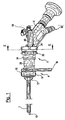
- the endoscope and shaft system shown as an embodiment consists essentially of two modules.
- the first assembly is formed by an access shaft 2 and a handle portion 4, which is detachably connected to the access shaft 2.
- the handle part 4 is known to be formed at its distal end with a receptacle for the proximal end of the access shaft 2 by means of a latching connection.
- the second assembly is formed from a connector 6 and an endoscope 8.
- the endoscope 8 is inserted from the proximal end into the connector 6 so that the optic shaft 10 of the endoscope extends distally into the access shaft 2.
- the endoscope 8 is detachably connected to the connecting piece 6, as will be described in more detail below.
- the access shaft 2 ends at its proximal end to a connecting piece 12. This is inserted into a distal-side receptacle 14 of the handle part 4 and there releasably connected via the locking elements 16 positively with the handle part 4.
- the handle part 4 An essential part of the handle part 4 is the handle 18, which extends radially outward. About the receptacle 14 and the connector 12, the handle is connected directly to the access shaft 2, so that manipulation forces can be transmitted directly to the access shaft 2 via the handle 18, without the endoscope 8 is loaded with these forces. In this way, relatively high manipulation forces can be applied to the access shaft 2.
- the handle part 4 at the proximal end of a cylindrical sleeve 20.
- This serves to connect to the connecting piece 6 and is inserted for this purpose from the distal end into the connecting piece 6.
- the handle part 4 and the connector 6 are thus simply plugged together and can be easily separated.
- the longitudinal axis X 1 of the cylindrical receptacle 14 and the longitudinal axis X 2 of the sleeve 20 by a dimension e offset parallel to each other, that is offset in the lateral direction.
- the offset e of the sleeve 20 relative to the receptacle 14 in the handle part 4 is related to the configuration of the access shaft 2.
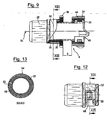
- the access shaft is shown in cross-section. It can be seen that the access shaft 2 has a substantially oval cross-section. That is, the extension or width B of the access shaft in a first cross-sectional direction is greater than the extension H in a second cross-sectional direction normal to the first cross-sectional direction.
- the optical shaft 10 is not arranged centrally but laterally offset in one half of the inner cross section of the access shaft 2.
- the longitudinal axis X E of the optical shaft 10 is offset parallel to the longitudinal or central axis Xz of the access shaft 2, which extends in extension of the longitudinal axis X 1 of the receptacle 14.
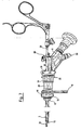
- a free lumen 22 remains in which a working instrument 24 can be used.
- This can be a pair of pliers, as in Fig. 7 is shown.
- the endoscope or optical shaft 10 and the working insert 24 optimally fill the inner cross section of the access shaft 2, while at the same time keeping the height H of the access shaft 2 low, so that the instrument can also be moved to the operating area via narrow access channels.
- the arrangement of the optical shaft 10 in the interior of the access shaft 2 in one half laterally offset with respect to the central axis Xz of the access shaft 2 is achieved by the offset e between the sleeve 20 and receptacle 14 in the handle part 4.
- the offset e ensures that the endoscope 8 remains rotatable about the longitudinal axis of the endoscope or optic shaft 10 in order to be able to rotate the field of view in the operating area.
- This rotation is achieved in that the connecting piece 6 on the sleeve 20 of the handle part 4 about the longitudinal axis X 2 of the sleeve 20 can be rotated.
- the endoscope 8 is positioned in the connecting piece 6 such that the longitudinal axis X E of the optical shaft 10 extends along the longitudinal axis X 2 of the connecting piece 6 and the sleeve 20.
- the connector 6 is, as best in the detail view of FIG. 9 can be seen, essentially of an inner sleeve 26 and an outer sleeve 28, which via threads 30 and 32 are engaged with each other.
- the thread 30 is formed as an external thread on the inner sleeve 26
- the thread 32 is formed as an internal thread on the inside of the outer sleeve 28.
- the inner sleeve 26 extends proximally out of the outer sleeve 28. There it is provided with a locking ring 34 on the outer circumference.
- the outer sleeve 28 is provided on the outer circumference with a collar 36 which projects radially outward.
- the inner sleeve 26 and the outer sleeve 28 can be grasped and rotated against each other. Through the threaded engagement they move in the axial direction apart or together, depending on the direction of rotation. In this way, an axial delivery by the dimension s is possible.
- the endoscope 8 is fixed, as will be explained in more detail below.
- the endoscope is also moved relative to the handle part 4 connected to the connecting piece 6 via the outer sleeve 28 and thus in the access shaft 2 in the axial direction. In this way, the distal end of the endoscope can also be moved by the dimension s by turning the two sleeves of the connecting piece 6.
- the inner sleeve 26 has at its proximal end a sector-shaped cut-out 38 which is open towards the proximal end.
- the extending in the longitudinal direction of the sleeve 26 and the cutout 38 bounding end faces of the sleeve 26 form two contact surfaces 40.
- the endoscope 8 has two projecting to opposite sides of shoulders 41, which extend parallel to the longitudinal direction X E of the endoscope. These shoulders 41 form contact surfaces 42, which are opposite to the contact surfaces 40 on the sleeve 26 and come to rest with them.
- the width of the endoscope 8 between the shoulders 41 is selected so that it corresponds to the width of the cutout 38.
- the endoscope 8 can be positively inserted into the cutout 38 in the sleeve.
- the endoscope 8 is located so that the endoscope shaft 10 extends centrally in the sleeve 26 in the direction of its longitudinal axis X 2 .
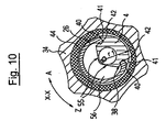
- the endoscope is fixed via a clamping ring 44, which surrounds the inner sleeve 26 on the outer circumference and is located in the interior of the annular locking ring 34.
- the clamping ring 44 is rotatable with the locking ring 34 about the sleeve 26 in the direction of the arrows A and Z.
- the rotation in the direction A causes a rotation in the open position, which in Fig. 10 is shown.
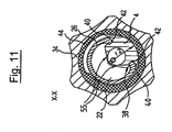
- the rotation in direction Z causes a rotation in the closed position, which in FIG. 11 is shown.
- the endoscope 8 is pressed against the contact surfaces 40 and clamped.
- the clamping ring 44 has a circumferentially changing diameter or radius on the inner circumference.
- a region of the clamping ring is located above the endoscope 8, which has a larger radius r 1 . This leaves a certain clearance between the clamping ring and the endoscope 8, so that it is not clamped.
- the area of the clamping ring 44 with a smaller inner radius r 2 comes to rest over the endoscope 8, as in FIG Fig. 11 shown so that the endoscope 8 is pressed with its contact surfaces 42 backlash against the contact surfaces 40 on the inner sleeve 26 and thus fixed to the sleeve 26 and thus in the connector 6.
- the endoscope 8 When the endoscope 8 is fixed in the connecting piece 6, it can be removed together with the connecting piece 6 from the grip part 4 and thus removed from the access shaft 2. This may be required if the entire internal cross section of the access shaft is needed, for example to remove larger amounts of tissue from the surgical field. Since in this removal of the endoscope 8 from the access shaft 2, the sleeves 26 and 28 of the connecting piece 6 are not rotated against each other, the positioning of the endoscope 8 is maintained in the axial direction. That is, when the endoscope 8 is again inserted into the access shaft 2 and the connecting piece 6 is connected to the grip part 4, the endoscope 8 is again in the same axial position as before the removal.
- the engagement of the connecting piece 6 and the handle part 4 takes place in such a way that the proximal-side sleeve 20 of the grip part 4 extends into the inner sleeve 26 of the connecting piece 6.
- the outer diameter of the sleeve 20 corresponds to the inner diameter of the inner sleeve 26.
- the outer sleeve 28 is provided at its distal end with a radially inwardly directed annular collar 46, which also comes to rest on the outer circumference of the sleeve 20.
- the outer sleeve 28 is provided in the region of the threaded engagement with the inner sleeve 26 with a spring element.
- the spring element is designed as a circumferentially extending tongue 48.
- the tongue 48 is thereby formed by a substantially U-shaped parting line 50 formed in the wall of the sleeve 28. This parting line 50 extends through the entire thickness of the wall of the sleeve 28 from the outer periphery to the inner periphery.
- the tongue 48 thus formed is provided at its free end with a radially outwardly projecting bead 52. As in Fig.
- the outer circumference of the sleeve 28 in the region in which the tongue 48 is formed substantially oval.
- the sleeve is circumferentially surrounded by a clamping ring 54.
- the bead 52 lies against the inner circumference of the clamping ring 54. This causes the tongue 48 to be pressed inwardly against the outer circumference of the inner sleeve 26. In this way, there is a clamping between the inner sleeve 26 and the outer sleeve 28, which eliminates the game from the engagement of the threads 30 and 32.
- the endoscope 8 is formed in the region with which it engages in the recess or the cutout 38 of the sleeve 26 in cross section roof edge, wherein the oblique outer sides 55 extend substantially tangentially to the outer periphery of the optical shaft 10.
- This embodiment of the endoscope in this area has the advantage that the endoscope covers in cross-section from the interior of the sleeve 26 only a sector smaller 180 degrees. The largest part of the cross section remains free and forms a free lumen 56. This covers the front side of the access shaft 2 in the region of the free lumen 22, which is provided for receiving the working instrument 24.
- the endoscope 8 is still rotated over a large angular range about its longitudinal axis X E by the sleeve 26 is rotated on the sleeve 20.
- the free lumen 56 of the sleeve 26 sweeps arcuately the area which is provided for receiving the working instrument 24.
- the free lumen 56 of the sleeve 26 and the free lumen 22 of the access shaft are in alignment and form a common free lumen from the proximal to the distal end. So can the endoscope 8 are rotated until the working tool 24 abuts one of the two inclined surfaces 55 of the roof edge profile of the endoscope 8.
- an endoscope and shaft system which on the one hand makes it possible to transmit large manipulation forces on the access shaft 2 and at the same time allows great mobility of the endoscope 8 in the interior of the access shaft 2.
- the endoscope 8 can be moved in the axial direction X E and rotated about its longitudinal axis X E. At the same time the endoscope 8 remains completely free of manipulation forces, which are transmitted from the handle 18 to the access shaft.
- the endoscope 8 is otherwise formed in a conventional manner, that is, it has an optical system, optical fibers for illumination and a flushing channel. For these, a flushing connection 58 and a light conductor connection 60 are provided on the proximal side.
- optical system may be a CCD element or the like, and instead of the light guide, one or more LED, as customary in a video endoscope, may be provided.
Description
- Die Erfindung betrifft ein Endoskop- und Schaftsystem zur Verwendung bei der endoskopischen Wirbelsäulenchirurgie, insbesondere im Bereich der Halswirbelsäule.
- Bei der endoskopischen Wirbelsdulenchirurgie, insbesondere im Bereich der Halswirbelsäule, ist anatomisch bedingt nur ein kleiner Zugangskanal möglich und dementsprechend können nur kleinkalibrige Endoskop- und Schaftsysteme verwendet werden. Die optimale Platzierung der Zugangsschäfte ist von vornherein schwierig und eine nachträgliche Korrektur ist in der Regel nur mit verhältnismäßig hohen Manipulationskräften möglich.
-
EP 0 455 188 A2 bildet den nächstkommenden Stand der Technik und offenbart ein Koagulationsinstrument zum Stillen von Blutungen in Nasenhöhlen. Dieses Instrument weist einen Zugangsschaft auf, an dessen proximalem Ende ein Kupplungsgehäuse ausgebildet ist, in welchem eine Aufnahme durch eine Feder vorgespannt so gehalten ist, dass sie um ihre Längsachse in bestimmten Schritten drehbar und um ein gewisses Maß gegen die Federvorspannung axial verschiebbar ist. In der Aufnahme ist mittels eines Spannrings eine Endoskopoptik fixiert. Diese Ausgestaltung hat den Nachteil, dass das Entfernen der Endoskopoptik zum einen nur einen begrenzten Querschnitt des Arbeitskanals freigibt und zum anderen die Positionierung des Endoskops durch Lösen des Spannrings verloren geht, sodass das Endoskop nach Wiedereinsetzen in das Instrument insbesondere in axialer Richtung neu positioniert werden muss. - Es ist Aufgabe der Erfindung ein Endoskop- und Schaftsystem bereitzustellen, welches es zum einen ermöglicht, große Manipulationskräfte auf den Zugangsschaft ohne Beschädigung und Beeinträchtigung der Bewegbarkeit des Endoskops zu übertragen, und es zum anderen ermöglicht, einen größeren Querschnitt des Zugangsschaftes zur Entnahme größerer Gewebemengen freizugeben, ohne die Positionierung des Endoskops zu beeinträchtigen.
- Diese Aufgabe wird durch ein Endoskop- und Schaftsystem mit den in Anspruch 1 angegebenen Merkmalen gelöst. Bevorzugte Ausführungsformen ergeben sich aus den Unteransprüchen.
- Das erfindungsgemäße Endoskop- und Schaftsystem weist einen Zugangsschaft sowie ein in den Zugangsschaft einsetzbares Endoskop auf. Der Zugangsschaft hat erfindungsgemäß an seinem proximalen Ende ein Griffteil. Dies hat den Vorteil, dass über das Griffteil Manipulationskräfte direkt auf den Zugangsschaft übertragen werden können, um diesen im Operationsgebiet zu positionieren. Das eingesetzte Endoskop bleibt dabei frei von den Manipulationskräften und ist vor Beschädigungen geschützt. Auf diese Weise können vergleichsweise große Manipulationskräfte übertragen werden, ohne dass das Endoskop hierfür besonders verstärkt ausgebildet werden müsste. Das Endoskop kann somit weiterhin sehr schlank angepasst an den zur Verfügung stehenden kleinen Zugangskanal ausgebildet werden, sodass der zur Verfügung stehende Raum optimal ausgenutzt werden kann.
- Das Endoskop ist durch ein Verbindungsstück gehalten. Dazu ist das Endoskop vorzugsweise lösbar mit dem Verbindungsstück verbunden. Das Verbindungsstück wiederum ist lösbar mit dem Griffteil verbunden bzw. verbindbar. So kann das Verbindungsstück gemeinsam mit dem Endoskop von dem Griffteil und dem Zugangsschaft getrennt werden, beispielsweise um andere Instrumente durch den Zugangsschaft ins Operationsgebiet zu führen. Die Handhabung des Zugangsschaftes kann dabei allein über das direkt mit dem Zugangsschaft verbundene Griffteil erfolgen. Ferner ist das Verbindungsstück, wenn es mit dem Griffteil verbunden ist um die Längsachse des Endoskops relativ zu dem Griffteil drehbar. Auf diese Weise kann das Endoskop im Zugangsschaft um seine Längsachse gedreht werden, um einen möglichst großen Bereich des Operationsgebietes mit dem Endoskop betrachten zu können.
- Das Endoskop ist nicht nur drehbar sondern auch axial beweglich. Eine solche axiale Beweglichkeit kann beispielsweise dadurch erreicht werden, dass das Verbindungsstück nicht nur relativ zu dem Griffteil drehbar sondern auch noch relativ zu dem Griffteil axial beweglich ist. Dabei wird dann das Endoskop gemeinsam mit dem Verbindungsstück axial verschoben und/oder gedreht, um das distale Ende des Endoskops so zu platzieren, dass ein gewünschter Bereich des Operationsgebietes betrachtet werden kann.
- Erfindungsgemäß wird somit ein Endoskop- und Schaftsystem geschaffen, welches zum einen die Übertragung vergleichsweise großer Manipulationskräfte ermöglicht und zum anderen gleichzeitig eine, vorzugsweise freie, Bewegbarkeit des Endoskops in dem Zugangsschaft ermöglicht.
- Bevorzugt sind das Griffteil und/oder das Verbindungsstück derart ausgebildet, dass das in dem Verbindungsstück gehaltene Endoskop mit seiner Längsachse parallel versetzt zu der Längsachse des Zugangsschaftes angeordnet ist. Auf diese Weise wird neben dem Endoskop im Querschnitt des Zugangsschaftes ein freies Lumen geschaffen, durch welches neben dem Endoskop ein Arbeitsinstrument durch den Zugangsschaft zum Operationsgebiet geführt werden kann.
- Weiter bevorzugt weist der Zugangsschaft eine Querschnittsform auf, welche in einer ersten Richtung eine größere Weite aufweist als in einer zweiten Richtung, welche normal zu der ersten Richtung ist. Das heißt der Zugangsschaft ist im Querschnitt nicht kreisförmig sondern im Wesentlichen oval ausgebildet. Dies ermöglicht es, den Zugangsschaft im Querschnitt mit möglichst geringer Höhe auszubilden, sodass er gut in den Bereich der Wirbelsäule insbesondere im Zwischenwirbelraum zuführbar ist. Gleichzeitig wird durch die im Querschnitt größere Breite ein ausreichend großes Lumen im Inneren des Zugangsschaftes geschaffen, durch welches ein Endoskop und ggf. weitere Instrumente zugeführt werden können. Wie oben beschrieben, ist bevorzugt das Endoskop so platziert, dass seine Längs- bzw. Mittelachse gegenüber der Längs- bzw. Mittelachse des Zugangsschaftes parallel versetzt ist. Das heißt idealerweise liegt im ovalen Querschnitt des Zugangsschaftes das Endoskop in der einen Hälfte und die andere Hälfte bildet ein freies Lumen, durch welches beispielsweise ein Arbeitsinstrument zugeführt werden kann.
- Der Zugangsschaft ist lösbar mit dem Griffteil verbunden. Dies ermöglicht es, das Instrument beim Einführen in den Zwischenwirbelraum mit anderen Instrumenten zu kombinieren und zu Reinigungs- oder Wartungszwecken zu zerlegen oder beispielsweise unterschiedliche Zugangsschäfte mit ein und demselben Griffteil zu verbinden. Weiter bevorzugt ist die Verbindung zwischen Griffteil und Zugangsschaft so ausgebildet, dass der Zugangsschaft in zwei möglichen Winkelpositionen mit dem Griffteil verbunden werden kann. Das heißt der Zugangsschaft kann um seine Längsachse um 180 Grad gedreht in einer zweiten möglichen Position mit dem Griffteil verbunden werden. Das ermöglicht bei ovaler Ausgestaltung des Zugangsschaftes und versetzter Anordnung des Endoskops, das Endoskop wahlweise in den beiden möglichen Positionen im Zugangsschaft zu positionieren. Die Verbindung zwischen Griffteil und Zugangsschaft ist beispielsweise als lösbare Kugelrastverbindung ausgebildet.
- Weiter bevorzugt weist das Griffteil an seinem distalen Ende eine Aufnahme für das proximale Ende des Zugangsschaftes auf und weist an seinem proximalen Ende eine Aufnahme für das Verbindungsstück auf, wobei diese beiden Aufnahmen zueinander in einer Richtung quer zur Längsachse des Zugangsschaftes parallel versetzt angeordnet sind. Auf diese Weise sorgt das Griffteil für die versetzte Anordnung von Endoskop und Zugangsschaft. Wenn das Endoskop mit dem Verbindungsstück verbunden ist, wird das Verbindungsstück in Richtung quer zur Längsachse des Zugangsschaftes durch das Griffteil definiert positioniert. Gleichzeitig bleibt jedoch die Drehbarkeit des Endoskops um seine Längsachse und vorzugsweise auch eine axiale Beweglichkeit des Endoskops in dem Zugangsschaft gewährleistet.
- Das Griffteil und das Verbindungsstück sind in axialer Richtung lösbar zusammengesteckt. Dies ermöglicht es, dass das Verbindungsstück leicht von dem Griffteil entfernt werden kann, um beispielsweise das Endoskop, welches mit dem Verbindungsstück verbunden ist, aus dem Zugangsschaft zu entnehmen. Dies kann erforderlich sein, wenn der gesamte Querschnitt des Zugangsschaftes benötigt wird, um größere Gewebemengen aus dem Operationsgebiet zu entfernen. Dadurch, dass das Endoskop mit dem Verbindungsstück verbunden bleibt, ist es möglich, dass durch die Entnahme des Endoskops die Positionierung des Endoskops nicht verloren geht. Das heißt wenn das Verbindungsstück wieder mit dem Griffteil zusammen gesteckt wird, befindet sich das Endoskop wieder in derselben Positionierung wie vor der Entnahme. Dies wird dadurch gewährleistet, dass das Endoskop über das Verbindungsstück positioniert wird, d. h. das Verbindungsstück ein Positioniermittel zum Positionieren des Endoskops in dem Zugangsschaft aufweist. Dies kann eine Positionierung in axialer Richtung und/oder eine Positionierung bezüglich der Winkellage des Endoskops um seine Längsachse beinhalten.
- Das Griffteil weist vorzugsweise am proximalen Ende eine Hülse auf, welche vom distalen Ende her in das Innere des Verbindungsstücks eingreift. Das heißt das Verbindungsstück weist an seinem distalen Ende eine Öffnung auf, welche in Größe und Querschnittsform an Form und Größe des Außenumfanges der Hülse an dem Griffteil angepasst ist. Vorzugsweise ist die Hülse kreiszylindrisch ausgebildet und die Öffnung an dem Verbindungsstück ist entsprechend zylindrisch ausgebildet. So kann eine relativ große Anlagefläche zwischen Verbindungsstück und Griffteil geschaffen werden, um eine sichere Positionierung und Führung des Verbindungsstückes an dem Griffteil sicherzustellen. Die Drehbarkeit des Endoskops um seine Längsachse wird vorzugsweise dadurch erreicht, dass die Hülse des Griffteiles sich im Inneren der distalseitigen Öffnung des Verbindungsstückes drehen kann. Das heißt, dass Verbindungsstück dreht sich, vorzugsweise frei, auf der Hülse an dem Griffteil.
- Weiter ist es bevorzugt, dass das Verbindungsstück, an seinem proximalen Ende eine Befestigungsaufnahme zum lösbaren Befestigen des Endoskops aufweist. Durch diese Befestigungsaufnahme wird das Endoskop definiert an dem Verbindungsstück gehalten bzw. positioniert. Dabei ist es bevorzugt, dass das Endoskop zu Reinigungs- und Wartungszwecken von dem Verbindungsstück gelöst werden kann. Ferner ermöglichst dies, dass unterschiedliche Endoskope an ein und demselben Verbindungsstück angebracht werden können.
- Die lösbare Befestigung des Endoskops ist vorzugsweise dadurch möglich, dass das Endoskop durch einen drehbaren Klemmring mit sich über den Umfang änderndem Innendurchmesser an zumindest einer Anlagefläche der Befestigungsaufnahme lösbar fixierbar ist. Der Klemmring ist so ausgebildet, dass er in einer gelösten Position so positioniert ist, dass ein größerer Abstand zwischen Klemmring und Anlagefläche gegeben ist, sodass das Endoskop zwischen beiden bewegbar ist. Durch Verdrehen des Klemmringes wird ein Bereich mit kleinerem Innendurchmesser mit der Anlagefläche zur Überdeckung gebracht. Dadurch verkleinert sich der radiale Abstand zwischen Klemmring und Anlagefläche, sodass das Endoskop mit einem korrespondierenden Befestigungsabschnitt zwischen dem Klemmring und der Anlagefläche eingeklemmt werden kann. Dabei ist die Befestigungsaufnahme weiter bevorzugt so ausgestaltet, dass neben dieser kraftschlüssigen Klemmung auch eine formschlüssige Positionierung des Endoskops gegeben ist, um das Endoskop in einer definierten Lage zu halten.
- Die Befestigungsaufnahme ist vorzugsweise von einer Hülse gebildet, welche am proximalen Ende einen sektorförmigen Ausschnitt aufweist, wobei die dem Ausschnitt zugewandten Stirnflächen der Hülse Anlageflächen für das Endoskop bilden. Das Endoskop weist einen korrespondierenden Befestigungsabschnitt auf, welcher in diesen sektorförmigen Ausschnitt eingesetzt werden kann. Dabei kommen Anlageflächen, welche an dem Endoskop ausgebildet sind, an den Anlageflächen der Ausnehmung, d. h. den Stirnflächen an dem Ausschnitt der Hülse zur Anlage. Wenn ein Klemmring, wie er vorangehend beschrieben wurde vorgesehen ist, wird durch Verdrehen des Klemmringes vorzugsweise das Endoskop mit seinen Anlageflächen gegen diese Stirnflächen der Hülse gedrückt und so an der Hülse fixiert.
- Gemäß einer weiteren bevorzugten Ausführungsform weist das Verbindungsstück eine Verstelleinrichtung auf, mittels welcher das Endoskop relativ zu dem Griffteil axial bewegbar ist. Das heißt über das Verbindungsstück ist eine axiale Positionierung des Endoskops in dem Zugangsschaft möglich. Die Anordnung der Verstelleinrichtung an dem Verbindungsstück hat den Vorteil, dass, wenn das Verbindungsstück von dem Griffteil getrennt wird, die Einstellung der Verstelleinrichtung hiervon unabhängig ist bzw. nicht beeinflusst wird, sodass dann wenn das Verbindungsstück wieder mit dem Griffteil verbunden wird, die vorherige Positionierung des Endoskops in dem Zugangsschaft wiederhergestellt ist.
- Zur Ausbildung der Verstelleinrichtung weist das Verbindungsstück weiter bevorzugt zwei ineinander greifende Hülsen auf, welche über ein Gewinde miteinander in Eingriff sind, wobei an einer ersten Hülseein Stellring zum Verdrehen angeordnet ist und damit axialen Verstellen der ersten Hülse relativ zu der zweiten Hülse. An einer dieser Hülsen ist bevorzugt das Endoskop in der oben beschrieben Weise befestigt. Der Stellring ist bevorzugt an der anderen Hülse angebracht. An der Hülse ohne Stellring ist vorzugsweise ein Verschlussring vorgesehen, um damit das Endoskop festzulegen. Die Hülse mit dem Stellring ist weiter bevorzugt auf eine am proximalen Ende des Griffteils ausgebildete Hülse aufgesteckt, wie es oben beschrieben wurde. So kann die Hülse mit dem Stellring auf der Hülse des Griffteiles verdreht werden, um das Endoskop um seine Längsachse zu drehen. Die Hülse an dem Griffteil erstreckt sich weiter bevorzugt soweit in das Innere des Verbindungsstückes hinein, dass es auch in die zweite Hülse, welche mit der Hülse mit dem Stellring über das Gewinde im Eingriff ist, eingreift. Die äußere der beiden Gewindehülsen weist weiter bevorzugt an ihrem dem Gewinde abgewandten Axialende einen sich radial nach innen erstreckenden Kragen auf, welcher einen Innendurchmesser im Wesentlichen wie die innere der beiden Gewindehülsen aufweist. Dadurch wird sichergestellt, dass beide Gewindehülsen am Außenumfang der Hülse des Griffteiles zur Anlage kommen können. Dies stellt eine verbesserte Führung und Positionierung des Verbindungsstückes an dem Griffteil sicher.
- Weiter ist es bevorzugt, dass zwischen den beiden Hülsen, welche über die Gewinde miteinander in Eingriff sind, ein Federelement angeordnet ist, welches eine Klemmkraft zwischen beiden Hülsen bewirkt. Ein solches Federelement kann dadurch das Spiel in dem Gewinde ausschalten oder konstant halten, sodass die beiden Hülsen vorzugsweise spielfrei mit einer gewissen Schwergängigkeit zueinander verstellt werden können. Auf diese Weise wird eine sehr präzise Verstellung möglich und eine unbeabsichtigte Verstellung verhindert. Das Federelement kann als Federzunge ausgebildet sein, welche sich in Umfangsrichtung erstreckt und durch eine im Wesentlichen U-förmig verlaufende Trennfuge in der Hülsenwandung ausgebildet ist. Auf diese Weise kann das Federelement beispielsweise in der äußeren der beiden Hülsen ausgebildet sein und von einem umgebenden ringförmigen Klemmelement radial nach innen gegen die innere der Gewindehülsen gedrückt werden.
- Weiterhin ist es bevorzugt, dass das Griffteil und das Verbindungsstück im Inneren ein sich axial erstreckendes freies Lumen aufweisen, welches mit dem freien Lumen im Inneren des Zugangsschaftes fluchtet. Dies bedeutet, dass, wenn das Endoskop in den Zugangsschaft eingesetzt ist, dort neben dem Endoskop ein freies Lumen verbleibt, welches proximalseitig mit dem freien Lumen im Griffteil und dem Verbindungsstück fluchtet, sodass sich ein durchgehender freier Kanal vom proximalen zum distalen Ende des Instrumentes erstreckt. Durch diesen können Instrumente eingeführt werden. Um dieses durchgehende freie Lumen zu schaffen, ist das Endoskop in dem Verbindungsstück und in dem Griffteil vorzugsweise außermittig am Innenumfang angeordnet, sodass daneben das freie Lumen verbleibt.
- Weiter bevorzugt ist das Endoskop im Bereich des Verbindungsstückes im Querschnitt dachkantförmig ausgebildet, sodass es einen Innenquerschnitt des Verbindungsstückes im Wesentlichen nur in einem Sektor kleiner 180 Grad ausfüllt. Durch diese Ausgestaltung wird erreicht, dass auch beim Verdrehen des Endoskops gemeinsam mit dem Verbindungsstück das durchgehende freie Lumen über einen möglichst großen Verdrehwinkel erhalten bleibt. In dem Verbindungsstück verbleibt bei eingesetztem Endoskop somit ein freier Sektor welcher größer 180 Grad ist, sodass ein etwa bogenförmiger Freiraum verbleibt. Beim Verdrehen des Verbindungsstückes überstreicht dieser freie Sektor bzw. Bogen das proximale Ende des freien Lumens des Zugangsschaftes, sodass ein durchgehender Durchgang auch durch das Verbindungsstück hindurch beim Verdrehen erhalten bleibt.
- Nachfolgend wir die Erfindung beispielhaft anhand der beigefügten Figuren beschrieben. In diesen zeigt:
- Fig. 1
- eine schematische Gesamtansicht eines erfindungsgemäßen Endoskop- und Schaftsystems im zusammengesetzten Zustand,
- Fig. 2
- eine teilweise geschnittene Ansicht des Endoskop- und Schaftsystems gemäß
Fig. 1 , - Fig. 3
- ein Endoskop- und Schaftsystem gemäß
Fig. 1 mit proximalwärts verlagertem Endoskop, - Fig. 4
- eine Schnittansicht des in
Fig. 3 gezeigten Endoskop- und Schaftsystems, - Fig. 5
- eine Querschnittansicht des Zugangsschaftes mit darin liegendem Endoskop,
- Fig. 6
- eine Draufsicht auf das Instrument gemäß
Fig. 1 bis 4 von der proximalen Seite her gesehen, - Fig. 7
- eine Gesamtansicht des Instrumentes gemäß
Fig. 1 bis 6 mit einem eingesetzten Hilfsinstrument, - Fig. 8
- eine Detailansicht des Griffteiles,
- Fig. 9
- eine Schnittansicht des Verbindungsstückes,
- Fig. 10
- eine Schnittansicht entlang der Linie X-X in
Fig. 1 , - Fig. 11
- eine Ansicht gemäß
Fig. 10 , wobei sich das Endoskop im geklemmten Zustand befindet, - Fig. 12
- eine Detailansicht der äußeren Hülse des Verbindungsstückes und
- Fig. 13
- eine Schnittansicht entlang der Linie XIII-XIII in
Fig. 12 . - Das als Ausführungsbeispiel gezeigte erfindungsgemäße Endoskop- und Schaftsystem besteht im Wesentlichen aus zwei Baugruppen. Die erste Baugruppe wird gebildet von einem Zugangsschaft 2 und einem Griffteil 4, welches mit dem Zugangsschaft 2 lösbar verbunden ist. Dazu ist das Griffteil 4 an seinem distalen Ende bekannterweise mit einer Aufnahme für das proximale Ende des Zugangsschaftes 2 mittels einer RastVerbindung ausgebildet.
- Die zweite Baugruppe ist gebildet aus einem Verbindungsstück 6 und einem Endoskop 8. Das Endoskop 8 ist vom proximalen Ende her in das Verbindungsstück 6 eingesetzt, sodass sich der Optikschaft 10 des Endoskops distalwärts in den Zugangsschaft 2 hinein erstreckt. Das Endoskop 8 ist lösbar mit dem Verbindungsstück 6 verbunden, wie weiter unten näher beschrieben wird.
- Der Zugangsschaft 2 endet an seinem proximalen Ende an einem Anschlussstück 12. Dieses ist in eine distalseitige Aufnahme 14 des Griffteils 4 eingesetzt und dort über die Rastelemente 16 lösbar formschlüssig mit dem Griffteil 4 verbunden.
- Wesentlicher Bestandteil des Griffteiles 4 ist der Griff 18, welcher sich radial nach außen erstreckt. Über die Aufnahme 14 und das Anschlussstück 12 ist der Griff direkt mit dem Zugangsschaft 2 verbunden, sodass über den Griff 18 Manipulationskräfte direkt auf den Zugangsschaft 2 übertragen werden können, ohne dass das Endoskop 8 mit diesen Kräften belastet wird. Auf diese Weise können auf den Zugangsschaft 2 vergleichsweise hohe Manipulationskräfte aufgebracht werden.
- Wie am besten in der Detailansicht in
Fig. 8 zu sehen ist, weist das Griffteil 4 am proximalen Ende eine zylindrische Hülse 20 auf. Diese dient zur Verbindung mit dem Verbindungsstück 6 und wird zu diesem Zweck vom distalen Ende her in das Verbindungsstück 6 eingesteckt. Das Griffteil 4 und das Verbindungsstück 6 werden somit einfach zusammengesteckt und können leicht voneinander getrennt werden. Wie inFig. 8 zu erkennen ist, sind die Längsachse X1 der zylindrischen Aufnahme 14 und die Längsachse X2 der Hülse 20 um ein Maß e parallel versetzt zueinander angeordnet, d. h. in lateraler Richtung versetzt. - Der Versatz e der Hülse 20 gegenüber der Aufnahme 14 in dem Griffteil 4 steht im Zusammenhang mit der Ausgestaltung des Zugangsschaftes 2. In
Fig. 5 ist der Zugangsschaft im Querschnitt gezeigt. Es ist zu erkennen, dass der Zugangsschaft 2 einen im Wesentlichen ovalen Querschnitt aufweist. Das heißt die Erstreckung bzw. Breite B des Zugangsschaftes in einer ersten Querschnittsrichtung ist größer als die Erstreckung bzw. Höhe H in einer zweiten zu der ersten Querschnittsrichtung normalen Querschnittsrichtung. Im Inneren des Zugangsschaftes 2 ist der Optikschaft 10 nicht zentral sondern seitlich versetzt in einer Hälfte des Innenquerschnittes des Zugangsschaftes 2 angeordnet. Das heißt die Längsachse XE des Optikschaftes 10 ist parallel versetzt zu der Längs- bzw. Mittelachse Xz des Zugangsschaftes 2, welche sich in Verlängerung der Längsachse X1 der Aufnahme 14 erstreckt. Auf diese Weise verbleibt ein freies Lumen 22 in welches ein Arbeitsinstrument 24 eingesetzt werden kann. Dies kann beispielhaft eine Zange sein, wie Sie inFig. 7 gezeigt ist. So füllen der Endoskop- bzw. Optikschaft 10 und der Arbeitseinsatz 24 den Innenquerschnitt des Zugangsschaftes 2 optimal aus, wobei gleichzeitig die Höhe H des Zugangsschaftes 2 gering gehalten wird, sodass das Instrument auch über enge Zugangskanäle zum Operationsgebiet bewegt werden kann. Die Anordnung des Optikschaftes 10 im Inneren des Zugangsschaftes 2 in einer Hälfte seitlich versetzt bezüglich der Mittelachse Xz des Zugangsschaftes 2 wird durch den Versatz e zwischen Hülse 20 und Aufnahme 14 in dem Griffteil 4 erreicht. Der Versatz e stellt dabei gleichzeitig sicher, dass das Endoskop 8 um die Längsachse des Endoskop- bzw. Optikschafts 10 drehbar bleibt, um das Blickfeld im Operationsgebiet drehen zu können. Diese Drehung wird dadurch erreicht, dass das Verbindungsstück 6 auf der Hülse 20 des Griffteiles 4 um die Längsachse X2 der Hülse 20 verdreht werden kann. Das Endoskop 8 ist dabei in dem Verbindungsstück 6 so positioniert, dass sich die Längsachse XE des Optikschafts 10 entlang der Längsachse X2 des Verbindungsstückes 6 und der Hülse 20 erstreckt. - Das Verbindungsstück 6 besteht, wie am besten in der Detailansicht von
Figur 9 zu erkennen ist, im Wesentlichen aus einer inneren Hülse 26 und einer äußeren Hülse 28, welche über Gewinde 30 und 32 miteinander in Eingriff sind. Das Gewinde 30 ist als Außengewinde auf der inneren Hülse 26 ausgebildet, das Gewinde 32 ist als Innengewinde auf der Innenseite der äußeren Hülse 28 ausgebildet. Die innere Hülse 26 erstreckt sich proximalwärts aus der äußeren Hülse 28 hinaus. Dort ist sie mit einem Verschlussring 34 am Außenumfang versehen. Die äußere Hülse 28 ist am Außenumfang mit einem Stellring 36 versehen, welcher radial nach außen auskragt. Über dem Verschlussring 34 und den Stellring 36 können die innere Hülse 26 und die äußere Hülse 28 ergriffen und gegeneinander verdreht werden. Durch den Gewindeeingriff bewegen sie sich dabei in axialer Richtung auseinander oder zusammen, je nach Drehrichtung. Auf diese Weise wird eine axiale Zustellung um das Maß s möglich. Am proximalen Ende der inneren Hülse 26 ist das Endoskop 8 festgelegt, wie nachfolgend näher erläutert werden wird. Dadurch wird bei Verstellung der äußeren Hülse 28 gegenüber der inneren Hülse 26 auch das Endoskop relativ zu dem über die äußere Hülse 28 mit dem Verbindungsstück 6 verbundenen Griffteil 4 und damit in axialer Richtung in dem Zugangsschaft 2 bewegt. Auf diese Weise kann das distale Ende des Endoskops ebenfalls um das Maß s durch Verdrehen der beiden Hülsen des Verbindungsstückes 6 bewegt werden. - Zur Verbindung mit dem Endoskop 8 weist die innere Hülse 26 an ihrem proximalen Ende einen zum proximalen Ende hin geöffneten sektorförmigen Ausschnitt 38 auf. Die sich in Längsrichtung der Hülse 26 erstreckenden und die Ausschnitt 38 begrenzenden Stirnflächen der Hülse 26 bilden zwei Anlageflächen 40. Das Endoskop 8 weist zwei zu entgegengesetzten Seiten auskragende Schultern 41 auf, welche sich parallel zur Längsrichtung XE des Endoskops erstrecken. Diese Schultern 41 bilden Anlageflächen 42, welche den Anlageflächen 40 an der Hülse 26 gegenüberliegen und mit diesen zur Anlage kommen. Die Breite des Endoskops 8 zwischen den Schultern 41 ist so gewählt, dass sie der Breite des Ausschnitts 38 entspricht. So kann das Endoskop 8 formschlüssig in den Ausschnitt 38 in der Hülse eingesetzt werden. Dabei ist das Endoskop 8 so gelegen, dass der Endoskopschaft 10 sich zentral in der Hülse 26 in Richtung deren Längsachse X2 erstreckt. Fixiert wird das Endoskop über einen Klemmring 44, welcher die innere Hülse 26 am Außenumfang umgibt und im Inneren des ringförmigen Verschlussringes 34 gelegen ist. Der Klemmring 44 ist mit dem Verschlussring 34 um die Hülse 26 in Richtung der Pfeile A und Z drehbar. Die Drehung in Richtung A bewirkt eine Drehung in die geöffnete Position, welche in
Fig. 10 gezeigt ist. Die Drehung in Richtung Z bewirkt eine Drehung in die geschlossene Position, welche inFigur 11 dargestellt ist. In der geschlossenen Position wird das Endoskop 8 gegen die Anlageflächen 40 gedrückt und so geklemmt. Dies erfolgt dadurch, dass der Klemmring 44 am Innenumfang einen sich über den Umfang ändernden Durchmesser bzw. Radius aufweist. In der gelösten Stellung inFig. 10 ist ein Bereich des Klemmringes über dem Endoskop 8 gelegen, welcher einen größeren Radius r1 aufweist. So verbleibt ein gewisses Spiel zwischen Klemmring und Endoskop 8, sodass dieses nicht geklemmt ist. Bei Drehung in Richtung des Pfeils Z kommt der Bereich des Klemmringes 44 mit geringerem Innenradius r2 über dem Endoskop 8 zu liegen, wie inFig. 11 gezeigt, sodass das Endoskop 8 mit seinen Anlageflächen 42 spielfrei gegen die Anlageflächen 40 an der inneren Hülse 26 gedrückt wird und somit an der Hülse 26 und damit in dem Verbindungsstück 6 fixiert wird. - Wenn das Endoskop 8 in dem Verbindungsstück 6 fixiert ist, kann es gemeinsam mit dem Verbindungsstück 6 von dem Griffteil 4 abgenommen und somit aus dem Zugangsschaft 2 entnommen werden. Dies kann erforderlich sein, wenn der gesamte Innenquerschnitt des Zugangsschaftes benötigt wird, um beispielsweise größere Gewebemengen aus dem Operationsgebiet zu entfernen. Da bei dieser Entnahme des Endoskops 8 aus dem Zugangsschaft 2 die Hülsen 26 und 28 des Verbindungsstückes 6 nicht gegeneinander verdreht werden, bleibt die Positionierung des Endoskops 8 in axialer Richtung erhalten. Das heißt, wenn das Endoskop 8 wieder in den Zugangsschaft 2 eingesetzt und das Verbindungsstück 6 mit dem Griffteil 4 verbunden ist, befindet sich das Endoskop 8 wieder in derselben axialen Position wie vor der Entnahme.
- Der Eingriff von Verbindungsstück 6 und Griffteil 4 erfolgt in der Weise, dass sich die proximalseitige Hülse 20 des Griffteiles 4 in die innere Hülse 26 des Verbindungsstückes 6 hinein erstreckt. Der Außendurchmesser der Hülse 20 entspricht dabei dem Innendurchmesser der inneren Hülse 26. Zusätzlich ist die äußere Hülse 28 an ihrem distalen Ende mit einem radial nach innen gerichteten ringförmigen Kragen 46 versehen, welcher ebenfalls am Außenumfang der Hülse 20 zur Anlage kommt. So ist auch dann, wenn die innere Hülse in proximaler Richtung verstellt ist, und der maximale Abstand s zwischen inneren Hülse 26 und der äußeren Hülse 28 erreicht wird, eine sichere Anlage des Verbindungsstückes 6 auf der Hülse 20 gewährleistet.
- Um eine spielfreie und gewisse schwergängige Verstellung der Hülsen 26 und 28 über den Eingriff der Gewinde 30, 32 zu gewährleisten, ist die äußere Hülse 28 im Bereich des Gewindeeingriffes mit der inneren Hülse 26 mit einem Federelement versehen. Das Federelement ist als eine sich in Umfangsrichtung erstreckende Zunge 48 ausgebildet. Die Zunge 48 wird dabei durch eine im Wesentlichen U-förmig verlaufende Trennfuge 50 in der Wandung der Hülse 28 gebildet. Diese Trennfuge 50 erstreckt sich durch die gesamte Stärke der Wandung der Hülse 28 vom Außenumfang zum Innenumfang. Die so gebildete Zunge 48 ist an ihrem freien Ende mit einem radial nach außen vorstehenden Wulst 52 versehen. Wie in
Fig. 13 zu erkennen ist, ist der Außenumfang der Hülse 28 in dem Bereich, in dem die Zunge 48 ausgebildet ist, im Wesentlichen oval. In diesem Bereich ist die Hülse umfänglich von einem Spannring 54 umgeben. Der Wulst 52 liegt dabei am Innenumfang des Spannringes 54 an. Dies bewirkt, dass die Zunge 48 nach innen gegen den Außenumfang der inneren Hülse 26 gedrückt wird. Auf diese Weise kommt es zu einer Klemmung zwischen der inneren Hülse 26 und der äußeren Hülse 28, welche das Spiel aus dem Eingriff der Gewinde 30 und 32 eliminiert. - Wie in den
Fig. 6 ,10 und11 zu erkennen ist, ist das Endoskop 8 in dem Bereich, mit welchem es in die Ausnehmung bzw. dem Ausschnitt 38 der Hülse 26 eingreift im Querschnitt dachkantförmig ausgebildet, wobei die schrägen Außenseiten 55 im Wesentlichen tangential zum Außenumfang des Optikschafts 10 verlaufen. Diese Ausgestaltung des Endoskops in diesem Bereich hat den Vorteil, dass das Endoskop im Querschnitt vom Innenraum der Hülse 26 nur einen Sektor kleiner 180 Grad überdeckt. Der größte Teil des Querschnittes bleibt frei und bildet ein freies Lumen 56. Dieses überdeckt die Stirnseite des Zugangsschaftes 2 im Bereich dessen freien Lumens 22, welches zur Aufnahme des Arbeitsinstrumentes 24 vorgesehen ist. Auf diese Weise kann auch dann, wenn ein solches Arbeitsinstrument 24 in dem Zugangsschaft 2 eingesetzt ist, dennoch das Endoskop 8 noch über einen großen Winkelbereich um seine Längsachse XE verdreht werden, indem die Hülse 26 auf der Hülse 20 verdreht wird. Das freie Lumen 56 der Hülse 26 überstreicht dabei bogenförmig den Bereich, welcher zur Aufnahme des Arbeitsinstrumentes 24 vorgesehen ist. So liegen das freie Lumen 56 der Hülse 26 und das freie Lumen 22 des Zugangsschaftes in einer Flucht und bilden ein gemeinsames freies Lumen vom proximalen zum distalen Ende. So kann das Endoskop 8 soweit gedreht werden, bis das Arbeitsinstrument 24 an eine der beiden schrägen Flächen 55 des Dachkantprofils des Endoskops 8 anstößt. - Insgesamt wird somit ein Endoskop- und Schaftsystem bereitgestellt, welches zum einen ermöglicht, große Manipulationskräfte auf den Zugangsschaft 2 zu übertragen und gleichzeitig eine große Beweglichkeit des Endoskops 8 im Inneren des Zugangsschaftes 2 ermöglicht. Das Endoskop 8 kann in axialer Richtung XE bewegt werden und um seine Längsachse XE verdreht werden. Gleichzeitig bleibt das Endoskop 8 völlig frei von Manipulationskräften, welche von dem Griff 18 auf den Zugangsschaft übertragen werden. Das Endoskop 8 ist im Übrigen in herkömmlicher Weise ausgebildet, d. h. es weist eine Optik, Lichtleiter zur Beleuchtung und einen Spülkanal auf. Für diese sind proximalseitig ein Spülanschluss 58 und ein Lichtleiteranschluss 60 vorgesehen.
- Anstelle des optischen Systems kann ein CCD-Element oder dergleichen und anstelle der Lichtleiter können ein oder mehrere LED, wie beispielsweise bei einem Videoendoskop üblich, vorgesehen sein.
-
- 2 -
- Zugangsschaft
- 4 -
- Griffteil
- 6 -
- Verbindungsstück
- 8 -
- Endoskop
- 10 -
- Optikschaft
- 12 -
- Anschlussstück
- 14 -
- Aufnahme
- 16 -
- Rastelement
- 18 -
- Griff
- 20 -
- Hülse
- 22 -
- freies Lumen
- 24 -
- Arbeitsinstrument
- 26 -
- innere Hülse
- 28 -
- äußere Hülse
- 30, 31 -
- Gewinde
- 34 -
- Verschlussring
- 36 -
- Stellring
- 38 -
- Ausschnitt
- 40 -
- Anlageflächen
- 41 -
- Schultern
- 42 -
- Anlageflächen
- 44 -
- Klemmring
- 46 -
- Kragen
- 48 -
- Zungen
- 50 -
- Spalt
- 52 -
- Wulst
- 54 -
- Spannring
- 55 -
- Flächen
- 56 -
- Lumen
- 58 -
- Spülanschluss
- 60 -
- Lichtleiteranschluss
- Z, A -
- Drehrichtungen des Klemmringes 44
- s -
- axialer Verstellweg
- e -
- Exzentrizität
- r1, r2 -
- Radien Klemmring
- Xz -
- Längsachse des Zugangsschaftes
- XE -
- Längsachse des Endoskopschaftes
- X1 -
- Längsachse der Aufnahme 14
- X2 -
- Längsachse der Hülse 20 und des Verbindungsstücks 6
Claims (14)
- Endoskop- und Schaftsystem mit einem Zugangsschaft (2) und einem
in den Zugangsschaft (2) einsetzbaren Endoskop (8), wobei der Zugangsschaft (2) an seinem proximalen Ende ein Griffteil (4) aufweist und das Endoskop (8) in einem Verbindungsstück (6) gehalten ist, dadurch gekennzeichnet, dass
das Griffteil (4) und das Verbindungsstück (6) in axialer Richtung lösbar zusammengesteckt sind, und das Verbindungsstück, wenn es mit dem Griffteil verbunden ist, um die Längsachse des Endoskops (8) relativ zu dem Griffteil (4) drehbar und axial verstellbar ist. - Endoskop- und Schaftsystem nach Anspruch 1, bei welchem das Griffteil (4) und/oder das Verbindungsstück (6) derart ausgebildet sind, dass das in dem Verbindungsstück (6) gehaltene Endoskop (8) mit seiner Längsachse parallel versetzt zu der Längsachse des Zugangsschaftes (2) angeordnet ist.
- Endoskop- und Schaftsystem nach einem der vorangehenden Ansprüche , bei welchem der Zugangsschaft (2) eine Querschnittsform hat, welche in einer ersten Richtung eine größere Weite aufweist als in einer zweiten zu der ersten Richtung normalen Richtung.
- Endoskop- und Schaftsystem nach einem der vorangehenden Ansprüche, bei welchem der Zugangsschaft (2) lösbar mit dem Griffteil (4) verbunden ist.
- Endoskop- und Schaftsystem nach einem der vorangehenden Ansprüche, bei welchem das Griffteil (4) an seinem distalen Ende eine Aufnahme (14) für das proximale Ende des Zugangsschaftes (2) aufweist und an seinem proximalen Ende eine Aufnahme (20) für das Verbindungsstück (6) aufweist, wobei diese beiden Aufnahmen (14, 20) in einer Richtung (e) quer zur Längsachse des Zugangsschaftes (2) zueinander versetzt angeordnet sind.
- Endoskop- und Schaftsystem nach einem der vorangehenden Ansprüche, bei welchem das Griffteil (4) am proximalen Ende eine Hülse (20) aufweist, welche vom distalen Ende her in das Innere des Verbindungsstückes (6) eingreift.
- Endoskop- und Schaftsystem nach einem der vorangehenden Ansprüche, bei welchem das Verbindungsstück (6) an seinem proximalen Ende eine Befestigungsaufnahme (38) zum lösbaren Befestigen des Endoskops (8) aufweist.
- Endoskop- und Schaftsystem nach Anspruch 7, bei welchem das Endoskop (8) durch einen drehbaren Klemmring (44) mit sich über den Umfang änderndem Innendurchmesser an zumindest einer Anlagefläche (40) der Befestigungsaufnahme (38) lösbar fixiert ist.
- Endoskop- und Schaftsystem nach Anspruch 8, bei welchem die Befestigungsaufnahme von einer Hülse (26) gebildet wird, welche am proximalen Ende einen sektorförmigen Ausschnitt (38) aufweist, wobei die dem Ausschnitt (38) zugewandten Stirnflächen der Hülse (26) Anlageflächen (40) für das Endoskop (8) bilden.
- Endoskop- und Schaftsystem nach einem der vorangehenden Ansprüche, bei welchem das Verbindungsstück (6) eine Verstelleinrichtung (30, 32) aufweist, mittels welcher das Endoskop (8) relativ zu dem Griffteil (4) axial bewegbar ist.
- Endoskop- und Schaftsystem nach Anspruch 10, bei welchem das Verbindungsstück (6) zwei ineinander greifende Hülsen (26, 28) aufweist, welche über ein Gewinde (30, 32) miteinander in Eingriff sind, wobei an einer ersten Hülse (28) ein Stellring (36) angeordnet ist zum Verdrehen und damit axialen Verstellen der ersten Hülse (28) relativ zu der zweiten Hülse (26).
- Endoskop- und Schaftsystem nach Anspruch 11, bei welchem zwischen den beiden Hülsen (26, 28) ein Federelement (48) angeordnet ist, welches eine Klemmkraft zwischen beiden Hülsen (26, 28) bewirkt.
- Endoskop- und Schaftsystem nach einem der vorangehenden Ansprüche, bei welchem das Griffteil (4) und das Verbindungsstück (6) im Inneren ein sich axial erstreckendes freies Lumen (56) aufweisen, welches mit dem freien Lumen (22) im Inneren des Zugangsschaftes (2) fluchtet.
- Endoskop- und Schaftsystem nach einem der vorangehenden Ansprüche, bei welchem das Endoskop (8) im Bereich des Verbindungsstückes (6) im Querschnitt dachkantförmig ausgebildet ist, so dass es einen Innenquerschnitt des Verbindungsstückes (6) im Wesentlichen nur in einem Sektor kleiner 180 Grad ausfüllt.
Applications Claiming Priority (1)
| Application Number | Priority Date | Filing Date | Title |
|---|---|---|---|
| DE102008029301A DE102008029301A1 (de) | 2008-06-19 | 2008-06-19 | Endoskop- und Schaftsystem |
Publications (2)
| Publication Number | Publication Date |
|---|---|
| EP2135542A1 EP2135542A1 (de) | 2009-12-23 |
| EP2135542B1 true EP2135542B1 (de) | 2012-09-05 |
Family
ID=41137854
Family Applications (1)
| Application Number | Title | Priority Date | Filing Date |
|---|---|---|---|
| EP09007594A Active EP2135542B1 (de) | 2008-06-19 | 2009-06-09 | Endoskop- und Schaftsystem |
Country Status (5)
| Country | Link |
|---|---|
| US (1) | US9597113B2 (de) |
| EP (1) | EP2135542B1 (de) |
| JP (1) | JP5043888B2 (de) |
| DE (1) | DE102008029301A1 (de) |
| ES (1) | ES2394401T3 (de) |
Cited By (2)
| Publication number | Priority date | Publication date | Assignee | Title |
|---|---|---|---|---|
| USD736924S1 (en) | 2014-01-23 | 2015-08-18 | Karl Storz Gmbh & Co. Kg | Trocar |
| DE102022202486B3 (de) | 2022-03-14 | 2023-08-24 | Richard Wolf Gmbh | Zielgerät zur gezielten Führung einer Hohlnadel bei einem endoskopisch-chirurgischen Eingriff |
Families Citing this family (13)
| Publication number | Priority date | Publication date | Assignee | Title |
|---|---|---|---|---|
| DE102012220651B4 (de) * | 2012-11-13 | 2016-10-06 | Richard Wolf Gmbh | Endoskop-Zwischenstück |
| EP3228254B1 (de) | 2014-02-21 | 2020-01-01 | 3DIntegrated ApS | Set mit einem chirurgischen instrument |
| CN103948365A (zh) * | 2014-05-13 | 2014-07-30 | 黎庆初 | 一种新型脊柱内窥镜工作通道系统 |
| CN104013381A (zh) * | 2014-05-29 | 2014-09-03 | 中山大学附属第三医院 | 三维椎间盘镜 |
| US11020144B2 (en) | 2015-07-21 | 2021-06-01 | 3Dintegrated Aps | Minimally invasive surgery system |
| WO2017012624A1 (en) | 2015-07-21 | 2017-01-26 | 3Dintegrated Aps | Cannula assembly kit, trocar assembly kit, sleeve assembly, minimally invasive surgery system and method therefor |
| DK178899B1 (en) | 2015-10-09 | 2017-05-08 | 3Dintegrated Aps | A depiction system |
| CN106618448B (zh) * | 2016-11-02 | 2018-09-28 | 张立军 | 一种内窥镜紧固及调节装置 |
| DE102017108272A1 (de) * | 2017-04-19 | 2018-10-25 | Carl Zeiss Meditec Ag | Endoskopische Sonde |
| WO2019172926A1 (en) * | 2018-03-09 | 2019-09-12 | Nido Surgical, Inc. | Instrument port including optical bulb secured to port body |
| US11324555B2 (en) | 2018-03-09 | 2022-05-10 | The Children's Medical Center Corporation | Instrument port including optical bulb secured to port body |
| CN108742475A (zh) * | 2018-07-17 | 2018-11-06 | 南京微来医学科技有限公司 | 手持式电子宫腔镜 |
| DE102022203780A1 (de) | 2022-04-14 | 2023-10-19 | Richard Wolf Gmbh | Endoskopisches Instrument |
Family Cites Families (19)
| Publication number | Priority date | Publication date | Assignee | Title |
|---|---|---|---|---|
| JPS5881029A (ja) | 1981-11-06 | 1983-05-16 | オリンパス光学工業株式会社 | レゼクトスコ−プ |
| GB2130889B (en) * | 1982-11-26 | 1986-06-18 | Wolf Gmbh Richard | Rectoscope |
| DE3319049A1 (de) * | 1982-11-26 | 1984-05-30 | Richard Wolf Gmbh, 7134 Knittlingen | Rektoskop |
| JP2664245B2 (ja) | 1989-05-12 | 1997-10-15 | オリンパス光学工業株式会社 | 硬性内視鏡装置 |
| DE4014350A1 (de) | 1990-05-04 | 1991-11-14 | Wolf Gmbh Richard | Koagulationsinstrument zum stillen von blutungen in nasenhoehlen |
| DE4417637A1 (de) * | 1994-05-19 | 1995-11-23 | Rudolf Dr Med Bertagnoli | Instrument zur perkutanen Behandlung von Gewebeteilen |
| DE4425705C2 (de) * | 1994-07-01 | 2002-08-01 | Storz Karl Gmbh & Co Kg | Endoskopisches Instrument |
| DE4444049A1 (de) * | 1994-12-10 | 1996-06-20 | Wolf Gmbh Richard | Vorrichtung für die Verbindung eines Endoskops mit einem Zusatzgerät |
| JP3665420B2 (ja) * | 1996-06-05 | 2005-06-29 | ペンタックス株式会社 | 内視鏡用案内装置 |
| TW375522B (en) * | 1996-10-24 | 1999-12-01 | Danek Medical Inc | Devices for percutaneous surgery under direct visualization and through an elongated cannula |
| JP3429685B2 (ja) * | 1997-10-06 | 2003-07-22 | オリンパス光学工業株式会社 | 内視鏡案内管 |
| US6196967B1 (en) * | 1998-03-18 | 2001-03-06 | Linvatec Corporation | Arthroscopic component joining system |
| DE19935725C2 (de) * | 1999-07-29 | 2003-11-13 | Wolf Gmbh Richard | Medizinisches Instrument, insbesondere Rektoskop |
| DE10310614B4 (de) * | 2002-03-25 | 2007-10-11 | Richard Wolf Gmbh | Resektoskop |
| DE202004014828U1 (de) * | 2004-09-21 | 2004-12-02 | Richard Wolf Gmbh | Endoskopisches Instrument |
| DE502005010766D1 (de) * | 2005-11-16 | 2011-02-10 | Wolf Gmbh Richard | Optisches Instrument |
| US20080208001A1 (en) * | 2007-02-26 | 2008-08-28 | Ron Hadani | Conforming endoscope |
| DE102007032201B4 (de) * | 2007-07-11 | 2013-08-14 | Schölly Fiberoptic GmbH | Endoskop |
| US20090054728A1 (en) * | 2007-08-21 | 2009-02-26 | Trusty Robert M | Manipulatable guide system and methods for natural orifice translumenal endoscopic surgery |
-
2008
- 2008-06-19 DE DE102008029301A patent/DE102008029301A1/de not_active Withdrawn
-
2009
- 2009-06-09 EP EP09007594A patent/EP2135542B1/de active Active
- 2009-06-09 ES ES09007594T patent/ES2394401T3/es active Active
- 2009-06-19 JP JP2009147015A patent/JP5043888B2/ja active Active
- 2009-06-19 US US12/488,003 patent/US9597113B2/en active Active
Cited By (3)
| Publication number | Priority date | Publication date | Assignee | Title |
|---|---|---|---|---|
| USD736924S1 (en) | 2014-01-23 | 2015-08-18 | Karl Storz Gmbh & Co. Kg | Trocar |
| DE102022202486B3 (de) | 2022-03-14 | 2023-08-24 | Richard Wolf Gmbh | Zielgerät zur gezielten Führung einer Hohlnadel bei einem endoskopisch-chirurgischen Eingriff |
| WO2023174493A1 (de) | 2022-03-14 | 2023-09-21 | Richard Wolf Gmbh | Zielgerät zur gezielten führung einer hohlnadel bei einem endoskopisch-chirurgischen eingriff |
Also Published As
| Publication number | Publication date |
|---|---|
| US20090318763A1 (en) | 2009-12-24 |
| JP5043888B2 (ja) | 2012-10-10 |
| EP2135542A1 (de) | 2009-12-23 |
| DE102008029301A1 (de) | 2009-12-24 |
| JP2010000361A (ja) | 2010-01-07 |
| ES2394401T3 (es) | 2013-01-31 |
| US9597113B2 (en) | 2017-03-21 |
Similar Documents
| Publication | Publication Date | Title |
|---|---|---|
| EP2135542B1 (de) | Endoskop- und Schaftsystem | |
| EP0860148B1 (de) | Bajonettkupplung zum lösbaren Verbinden zweier Rohrschaftinstrumente oder -instrumententeile | |
| EP1537829B1 (de) | Medizinisches Instrument mit Instrumenteneinsatz und Mittel zur Blockierung des beweglichen Griffteils | |
| EP0925028B1 (de) | Zerlegbares medizinisches instrument mit selbstorientierender kupplung | |
| EP2962651B1 (de) | Medizinischer schraubendreher und schaft für den medizinischen schraubendreher | |
| EP1523932B1 (de) | Endoskop | |
| EP1297790B1 (de) | Chirurgisches Zielgerät | |
| EP1779792A1 (de) | Facettengelenkfräser | |
| DE102016108504A1 (de) | Medizintechnisches Instrument zur provisorischen Fixierung einer polyaxialen Pedikelschraube | |
| DE102005032197B4 (de) | Endoskopisches Instrument | |
| EP2581031A1 (de) | Abwinkelungsvorrichtung | |
| EP3744270B1 (de) | System zur positionierung | |
| EP3351191B1 (de) | Chirurgisches instrument, insbesondere für die neurochirurgie | |
| DE19901389B4 (de) | Endoskopisches Behandlungssystem | |
| DE102005050031A1 (de) | Chirurgisches Instrument zum Entfernen eines Zwischenwirbelimplantats | |
| EP2853212B1 (de) | Chirurgisches Instrument | |
| EP3737987B1 (de) | Videoendoskop | |
| EP1637065A1 (de) | Endoskopisches Instrument | |
| DE10333956B4 (de) | Sichtobturator | |
| WO2023194131A1 (de) | Medizinisches werkzeugsystem | |
| DE4425705A1 (de) | Endoskopisches Instrument | |
| EP3968836B1 (de) | Gewebeclip-applikations-ausrüst- oder nachrüstsatz | |
| EP2258285B1 (de) | Medizinische Stanze | |
| EP1303219B1 (de) | Medizinisches instrument, insbesondere resektoskop | |
| DE202007000427U1 (de) | Chirurgischer Haltegriff und chirurgisches Instrument |
Legal Events
| Date | Code | Title | Description |
|---|---|---|---|
| PUAI | Public reference made under article 153(3) epc to a published international application that has entered the european phase |
Free format text: ORIGINAL CODE: 0009012 |
|
| AK | Designated contracting states |
Kind code of ref document: A1 Designated state(s): AT BE BG CH CY CZ DE DK EE ES FI FR GB GR HR HU IE IS IT LI LT LU LV MC MK MT NL NO PL PT RO SE SI SK TR |
|
| 17P | Request for examination filed |
Effective date: 20100324 |
|
| 17Q | First examination report despatched |
Effective date: 20100414 |
|
| GRAP | Despatch of communication of intention to grant a patent |
Free format text: ORIGINAL CODE: EPIDOSNIGR1 |
|
| GRAC | Information related to communication of intention to grant a patent modified |
Free format text: ORIGINAL CODE: EPIDOSCIGR1 |
|
| GRAS | Grant fee paid |
Free format text: ORIGINAL CODE: EPIDOSNIGR3 |
|
| GRAJ | Information related to disapproval of communication of intention to grant by the applicant or resumption of examination proceedings by the epo deleted |
Free format text: ORIGINAL CODE: EPIDOSDIGR1 |
|
| GRAL | Information related to payment of fee for publishing/printing deleted |
Free format text: ORIGINAL CODE: EPIDOSDIGR3 |
|
| GRAS | Grant fee paid |
Free format text: ORIGINAL CODE: EPIDOSNIGR3 |
|
| GRAP | Despatch of communication of intention to grant a patent |
Free format text: ORIGINAL CODE: EPIDOSNIGR1 |
|
| GRAA | (expected) grant |
Free format text: ORIGINAL CODE: 0009210 |
|
| AK | Designated contracting states |
Kind code of ref document: B1 Designated state(s): AT BE BG CH CY CZ DE DK EE ES FI FR GB GR HR HU IE IS IT LI LT LU LV MC MK MT NL NO PL PT RO SE SI SK TR |
|
| REG | Reference to a national code |
Ref country code: GB Ref legal event code: FG4D Free format text: NOT ENGLISH |
|
| REG | Reference to a national code |
Ref country code: CH Ref legal event code: EP |
|
| REG | Reference to a national code |
Ref country code: AT Ref legal event code: REF Ref document number: 573707 Country of ref document: AT Kind code of ref document: T Effective date: 20120915 |
|
| REG | Reference to a national code |
Ref country code: IE Ref legal event code: FG4D Free format text: LANGUAGE OF EP DOCUMENT: GERMAN |
|
| REG | Reference to a national code |
Ref country code: DE Ref legal event code: R096 Ref document number: 502009004587 Country of ref document: DE Effective date: 20121031 |
|
| REG | Reference to a national code |
Ref country code: CH Ref legal event code: NV Representative=s name: ISLER AND PEDRAZZINI AG, CH |
|
| REG | Reference to a national code |
Ref country code: NL Ref legal event code: VDEP Effective date: 20120905 |
|
| PG25 | Lapsed in a contracting state [announced via postgrant information from national office to epo] |
Ref country code: HR Free format text: LAPSE BECAUSE OF FAILURE TO SUBMIT A TRANSLATION OF THE DESCRIPTION OR TO PAY THE FEE WITHIN THE PRESCRIBED TIME-LIMIT Effective date: 20120905 Ref country code: FI Free format text: LAPSE BECAUSE OF FAILURE TO SUBMIT A TRANSLATION OF THE DESCRIPTION OR TO PAY THE FEE WITHIN THE PRESCRIBED TIME-LIMIT Effective date: 20120905 Ref country code: CY Free format text: LAPSE BECAUSE OF FAILURE TO SUBMIT A TRANSLATION OF THE DESCRIPTION OR TO PAY THE FEE WITHIN THE PRESCRIBED TIME-LIMIT Effective date: 20120905 Ref country code: LT Free format text: LAPSE BECAUSE OF FAILURE TO SUBMIT A TRANSLATION OF THE DESCRIPTION OR TO PAY THE FEE WITHIN THE PRESCRIBED TIME-LIMIT Effective date: 20120905 Ref country code: NO Free format text: LAPSE BECAUSE OF FAILURE TO SUBMIT A TRANSLATION OF THE DESCRIPTION OR TO PAY THE FEE WITHIN THE PRESCRIBED TIME-LIMIT Effective date: 20121205 |
|
| REG | Reference to a national code |
Ref country code: ES Ref legal event code: FG2A Ref document number: 2394401 Country of ref document: ES Kind code of ref document: T3 Effective date: 20130131 |
|
| REG | Reference to a national code |
Ref country code: LT Ref legal event code: MG4D Effective date: 20120905 |
|
| PG25 | Lapsed in a contracting state [announced via postgrant information from national office to epo] |
Ref country code: GR Free format text: LAPSE BECAUSE OF FAILURE TO SUBMIT A TRANSLATION OF THE DESCRIPTION OR TO PAY THE FEE WITHIN THE PRESCRIBED TIME-LIMIT Effective date: 20121206 Ref country code: LV Free format text: LAPSE BECAUSE OF FAILURE TO SUBMIT A TRANSLATION OF THE DESCRIPTION OR TO PAY THE FEE WITHIN THE PRESCRIBED TIME-LIMIT Effective date: 20120905 Ref country code: SE Free format text: LAPSE BECAUSE OF FAILURE TO SUBMIT A TRANSLATION OF THE DESCRIPTION OR TO PAY THE FEE WITHIN THE PRESCRIBED TIME-LIMIT Effective date: 20120905 Ref country code: SI Free format text: LAPSE BECAUSE OF FAILURE TO SUBMIT A TRANSLATION OF THE DESCRIPTION OR TO PAY THE FEE WITHIN THE PRESCRIBED TIME-LIMIT Effective date: 20120905 |
|
| PG25 | Lapsed in a contracting state [announced via postgrant information from national office to epo] |
Ref country code: RO Free format text: LAPSE BECAUSE OF FAILURE TO SUBMIT A TRANSLATION OF THE DESCRIPTION OR TO PAY THE FEE WITHIN THE PRESCRIBED TIME-LIMIT Effective date: 20120905 Ref country code: CZ Free format text: LAPSE BECAUSE OF FAILURE TO SUBMIT A TRANSLATION OF THE DESCRIPTION OR TO PAY THE FEE WITHIN THE PRESCRIBED TIME-LIMIT Effective date: 20120905 Ref country code: NL Free format text: LAPSE BECAUSE OF FAILURE TO SUBMIT A TRANSLATION OF THE DESCRIPTION OR TO PAY THE FEE WITHIN THE PRESCRIBED TIME-LIMIT Effective date: 20120905 Ref country code: EE Free format text: LAPSE BECAUSE OF FAILURE TO SUBMIT A TRANSLATION OF THE DESCRIPTION OR TO PAY THE FEE WITHIN THE PRESCRIBED TIME-LIMIT Effective date: 20120905 Ref country code: IS Free format text: LAPSE BECAUSE OF FAILURE TO SUBMIT A TRANSLATION OF THE DESCRIPTION OR TO PAY THE FEE WITHIN THE PRESCRIBED TIME-LIMIT Effective date: 20130105 |
|
| PG25 | Lapsed in a contracting state [announced via postgrant information from national office to epo] |
Ref country code: SK Free format text: LAPSE BECAUSE OF FAILURE TO SUBMIT A TRANSLATION OF THE DESCRIPTION OR TO PAY THE FEE WITHIN THE PRESCRIBED TIME-LIMIT Effective date: 20120905 Ref country code: PT Free format text: LAPSE BECAUSE OF FAILURE TO SUBMIT A TRANSLATION OF THE DESCRIPTION OR TO PAY THE FEE WITHIN THE PRESCRIBED TIME-LIMIT Effective date: 20130107 Ref country code: PL Free format text: LAPSE BECAUSE OF FAILURE TO SUBMIT A TRANSLATION OF THE DESCRIPTION OR TO PAY THE FEE WITHIN THE PRESCRIBED TIME-LIMIT Effective date: 20120905 |
|
| PLBI | Opposition filed |
Free format text: ORIGINAL CODE: 0009260 |
|
| PLAX | Notice of opposition and request to file observation + time limit sent |
Free format text: ORIGINAL CODE: EPIDOSNOBS2 |
|
| 26 | Opposition filed |
Opponent name: KARL STORZ GMBH & CO. KG Effective date: 20130529 |
|
| PG25 | Lapsed in a contracting state [announced via postgrant information from national office to epo] |
Ref country code: DK Free format text: LAPSE BECAUSE OF FAILURE TO SUBMIT A TRANSLATION OF THE DESCRIPTION OR TO PAY THE FEE WITHIN THE PRESCRIBED TIME-LIMIT Effective date: 20120905 Ref country code: BG Free format text: LAPSE BECAUSE OF FAILURE TO SUBMIT A TRANSLATION OF THE DESCRIPTION OR TO PAY THE FEE WITHIN THE PRESCRIBED TIME-LIMIT Effective date: 20121205 |
|
| REG | Reference to a national code |
Ref country code: DE Ref legal event code: R026 Ref document number: 502009004587 Country of ref document: DE Effective date: 20130529 |
|
| PLBB | Reply of patent proprietor to notice(s) of opposition received |
Free format text: ORIGINAL CODE: EPIDOSNOBS3 |
|
| BERE | Be: lapsed |
Owner name: RICHARD WOLF G.M.B.H. Effective date: 20130630 |
|
| PG25 | Lapsed in a contracting state [announced via postgrant information from national office to epo] |
Ref country code: MC Free format text: LAPSE BECAUSE OF FAILURE TO SUBMIT A TRANSLATION OF THE DESCRIPTION OR TO PAY THE FEE WITHIN THE PRESCRIBED TIME-LIMIT Effective date: 20120905 |
|
| REG | Reference to a national code |
Ref country code: IE Ref legal event code: MM4A |
|
| PG25 | Lapsed in a contracting state [announced via postgrant information from national office to epo] |
Ref country code: BE Free format text: LAPSE BECAUSE OF NON-PAYMENT OF DUE FEES Effective date: 20130630 |
|
| PG25 | Lapsed in a contracting state [announced via postgrant information from national office to epo] |
Ref country code: IE Free format text: LAPSE BECAUSE OF NON-PAYMENT OF DUE FEES Effective date: 20130609 |
|
| PG25 | Lapsed in a contracting state [announced via postgrant information from national office to epo] |
Ref country code: MT Free format text: LAPSE BECAUSE OF FAILURE TO SUBMIT A TRANSLATION OF THE DESCRIPTION OR TO PAY THE FEE WITHIN THE PRESCRIBED TIME-LIMIT Effective date: 20120905 |
|
| PLCK | Communication despatched that opposition was rejected |
Free format text: ORIGINAL CODE: EPIDOSNREJ1 |
|
| PG25 | Lapsed in a contracting state [announced via postgrant information from national office to epo] |
Ref country code: TR Free format text: LAPSE BECAUSE OF FAILURE TO SUBMIT A TRANSLATION OF THE DESCRIPTION OR TO PAY THE FEE WITHIN THE PRESCRIBED TIME-LIMIT Effective date: 20120905 |
|
| APAH | Appeal reference modified |
Free format text: ORIGINAL CODE: EPIDOSCREFNO |
|
| APBM | Appeal reference recorded |
Free format text: ORIGINAL CODE: EPIDOSNREFNO |
|
| APBP | Date of receipt of notice of appeal recorded |
Free format text: ORIGINAL CODE: EPIDOSNNOA2O |
|
| PG25 | Lapsed in a contracting state [announced via postgrant information from national office to epo] |
Ref country code: LU Free format text: LAPSE BECAUSE OF NON-PAYMENT OF DUE FEES Effective date: 20130609 Ref country code: MK Free format text: LAPSE BECAUSE OF FAILURE TO SUBMIT A TRANSLATION OF THE DESCRIPTION OR TO PAY THE FEE WITHIN THE PRESCRIBED TIME-LIMIT Effective date: 20120905 Ref country code: HU Free format text: LAPSE BECAUSE OF FAILURE TO SUBMIT A TRANSLATION OF THE DESCRIPTION OR TO PAY THE FEE WITHIN THE PRESCRIBED TIME-LIMIT; INVALID AB INITIO Effective date: 20090609 |
|
| REG | Reference to a national code |
Ref country code: AT Ref legal event code: MM01 Ref document number: 573707 Country of ref document: AT Kind code of ref document: T Effective date: 20140609 |
|
| APBQ | Date of receipt of statement of grounds of appeal recorded |
Free format text: ORIGINAL CODE: EPIDOSNNOA3O |
|
| PG25 | Lapsed in a contracting state [announced via postgrant information from national office to epo] |
Ref country code: AT Free format text: LAPSE BECAUSE OF NON-PAYMENT OF DUE FEES Effective date: 20140609 |
|
| REG | Reference to a national code |
Ref country code: FR Ref legal event code: PLFP Year of fee payment: 8 |
|
| REG | Reference to a national code |
Ref country code: FR Ref legal event code: PLFP Year of fee payment: 9 |
|
| PLAB | Opposition data, opponent's data or that of the opponent's representative modified |
Free format text: ORIGINAL CODE: 0009299OPPO |
|
| R26 | Opposition filed (corrected) |
Opponent name: KARL STORZ SE & CO. KG Effective date: 20130529 |
|
| REG | Reference to a national code |
Ref country code: FR Ref legal event code: PLFP Year of fee payment: 10 |
|
| APAH | Appeal reference modified |
Free format text: ORIGINAL CODE: EPIDOSCREFNO |
|
| REG | Reference to a national code |
Ref country code: DE Ref legal event code: R100 Ref document number: 502009004587 Country of ref document: DE |
|
| APBU | Appeal procedure closed |
Free format text: ORIGINAL CODE: EPIDOSNNOA9O |
|
| PLBN | Opposition rejected |
Free format text: ORIGINAL CODE: 0009273 |
|
| STAA | Information on the status of an ep patent application or granted ep patent |
Free format text: STATUS: OPPOSITION REJECTED |
|
| 27O | Opposition rejected |
Effective date: 20200224 |
|
| PGFP | Annual fee paid to national office [announced via postgrant information from national office to epo] |
Ref country code: FR Payment date: 20230622 Year of fee payment: 15 Ref country code: DE Payment date: 20230619 Year of fee payment: 15 |
|
| PGFP | Annual fee paid to national office [announced via postgrant information from national office to epo] |
Ref country code: IT Payment date: 20230630 Year of fee payment: 15 Ref country code: GB Payment date: 20230622 Year of fee payment: 15 Ref country code: ES Payment date: 20230719 Year of fee payment: 15 Ref country code: CH Payment date: 20230702 Year of fee payment: 15 |