EP2128396B1 - Störungsdiagnosevorrichtung und störungsdiagnoseverfahren für einen nox-sensor - Google Patents
Störungsdiagnosevorrichtung und störungsdiagnoseverfahren für einen nox-sensor Download PDFInfo
- Publication number
- EP2128396B1 EP2128396B1 EP08703886A EP08703886A EP2128396B1 EP 2128396 B1 EP2128396 B1 EP 2128396B1 EP 08703886 A EP08703886 A EP 08703886A EP 08703886 A EP08703886 A EP 08703886A EP 2128396 B1 EP2128396 B1 EP 2128396B1
- Authority
- EP
- European Patent Office
- Prior art keywords
- sensor
- exhaust
- value
- flow rate
- detected
- Prior art date
- Legal status (The legal status is an assumption and is not a legal conclusion. Google has not performed a legal analysis and makes no representation as to the accuracy of the status listed.)
- Active
Links
- 238000000034 method Methods 0.000 title claims abstract description 31
- 230000015556 catabolic process Effects 0.000 title 2
- 238000003745 diagnosis Methods 0.000 claims abstract description 124
- 238000002485 combustion reaction Methods 0.000 claims abstract description 32
- 230000007704 transition Effects 0.000 claims abstract description 26
- 230000004043 responsiveness Effects 0.000 claims abstract description 22
- 239000004071 soot Substances 0.000 claims description 3
- 239000000446 fuel Substances 0.000 abstract description 29
- 230000006866 deterioration Effects 0.000 abstract description 10
- 239000003638 chemical reducing agent Substances 0.000 description 63
- 239000003054 catalyst Substances 0.000 description 35
- 238000002347 injection Methods 0.000 description 34
- 239000007924 injection Substances 0.000 description 34
- 238000000746 purification Methods 0.000 description 29
- 238000001514 detection method Methods 0.000 description 10
- 230000005856 abnormality Effects 0.000 description 8
- 238000010276 construction Methods 0.000 description 8
- 238000011144 upstream manufacturing Methods 0.000 description 8
- 238000006722 reduction reaction Methods 0.000 description 7
- 230000002829 reductive effect Effects 0.000 description 7
- 239000004215 Carbon black (E152) Substances 0.000 description 5
- 229930195733 hydrocarbon Natural products 0.000 description 5
- 150000002430 hydrocarbons Chemical class 0.000 description 5
- 238000010586 diagram Methods 0.000 description 4
- 238000006243 chemical reaction Methods 0.000 description 3
- 230000002542 deteriorative effect Effects 0.000 description 3
- 239000000203 mixture Substances 0.000 description 3
- 239000000243 solution Substances 0.000 description 3
- WTHDKMILWLGDKL-UHFFFAOYSA-N urea;hydrate Chemical compound O.NC(N)=O WTHDKMILWLGDKL-UHFFFAOYSA-N 0.000 description 3
- 230000004075 alteration Effects 0.000 description 2
- 238000007599 discharging Methods 0.000 description 2
- 239000000463 material Substances 0.000 description 2
- 230000001052 transient effect Effects 0.000 description 2
- UGFAIRIUMAVXCW-UHFFFAOYSA-N Carbon monoxide Chemical compound [O+]#[C-] UGFAIRIUMAVXCW-UHFFFAOYSA-N 0.000 description 1
- XSQUKJJJFZCRTK-UHFFFAOYSA-N Urea Chemical compound NC(N)=O XSQUKJJJFZCRTK-UHFFFAOYSA-N 0.000 description 1
- 230000002159 abnormal effect Effects 0.000 description 1
- 239000004202 carbamide Substances 0.000 description 1
- 238000010531 catalytic reduction reaction Methods 0.000 description 1
- 239000000470 constituent Substances 0.000 description 1
- 239000000498 cooling water Substances 0.000 description 1
- 230000003111 delayed effect Effects 0.000 description 1
- 230000000694 effects Effects 0.000 description 1
Images


Classifications
-
- F—MECHANICAL ENGINEERING; LIGHTING; HEATING; WEAPONS; BLASTING
- F02—COMBUSTION ENGINES; HOT-GAS OR COMBUSTION-PRODUCT ENGINE PLANTS
- F02D—CONTROLLING COMBUSTION ENGINES
- F02D41/00—Electrical control of supply of combustible mixture or its constituents
- F02D41/22—Safety or indicating devices for abnormal conditions
- F02D41/222—Safety or indicating devices for abnormal conditions relating to the failure of sensors or parameter detection devices
-
- B—PERFORMING OPERATIONS; TRANSPORTING
- B01—PHYSICAL OR CHEMICAL PROCESSES OR APPARATUS IN GENERAL
- B01D—SEPARATION
- B01D53/00—Separation of gases or vapours; Recovering vapours of volatile solvents from gases; Chemical or biological purification of waste gases, e.g. engine exhaust gases, smoke, fumes, flue gases, aerosols
- B01D53/34—Chemical or biological purification of waste gases
- B01D53/74—General processes for purification of waste gases; Apparatus or devices specially adapted therefor
- B01D53/86—Catalytic processes
-
- B—PERFORMING OPERATIONS; TRANSPORTING
- B01—PHYSICAL OR CHEMICAL PROCESSES OR APPARATUS IN GENERAL
- B01D—SEPARATION
- B01D53/00—Separation of gases or vapours; Recovering vapours of volatile solvents from gases; Chemical or biological purification of waste gases, e.g. engine exhaust gases, smoke, fumes, flue gases, aerosols
- B01D53/34—Chemical or biological purification of waste gases
- B01D53/92—Chemical or biological purification of waste gases of engine exhaust gases
- B01D53/94—Chemical or biological purification of waste gases of engine exhaust gases by catalytic processes
-
- F—MECHANICAL ENGINEERING; LIGHTING; HEATING; WEAPONS; BLASTING
- F01—MACHINES OR ENGINES IN GENERAL; ENGINE PLANTS IN GENERAL; STEAM ENGINES
- F01N—GAS-FLOW SILENCERS OR EXHAUST APPARATUS FOR MACHINES OR ENGINES IN GENERAL; GAS-FLOW SILENCERS OR EXHAUST APPARATUS FOR INTERNAL COMBUSTION ENGINES
- F01N11/00—Monitoring or diagnostic devices for exhaust-gas treatment apparatus, e.g. for catalytic activity
-
- F—MECHANICAL ENGINEERING; LIGHTING; HEATING; WEAPONS; BLASTING
- F01—MACHINES OR ENGINES IN GENERAL; ENGINE PLANTS IN GENERAL; STEAM ENGINES
- F01N—GAS-FLOW SILENCERS OR EXHAUST APPARATUS FOR MACHINES OR ENGINES IN GENERAL; GAS-FLOW SILENCERS OR EXHAUST APPARATUS FOR INTERNAL COMBUSTION ENGINES
- F01N3/00—Exhaust or silencing apparatus having means for purifying, rendering innocuous, or otherwise treating exhaust
- F01N3/08—Exhaust or silencing apparatus having means for purifying, rendering innocuous, or otherwise treating exhaust for rendering innocuous
- F01N3/0807—Exhaust or silencing apparatus having means for purifying, rendering innocuous, or otherwise treating exhaust for rendering innocuous by using absorbents or adsorbents
-
- F—MECHANICAL ENGINEERING; LIGHTING; HEATING; WEAPONS; BLASTING
- F01—MACHINES OR ENGINES IN GENERAL; ENGINE PLANTS IN GENERAL; STEAM ENGINES
- F01N—GAS-FLOW SILENCERS OR EXHAUST APPARATUS FOR MACHINES OR ENGINES IN GENERAL; GAS-FLOW SILENCERS OR EXHAUST APPARATUS FOR INTERNAL COMBUSTION ENGINES
- F01N3/00—Exhaust or silencing apparatus having means for purifying, rendering innocuous, or otherwise treating exhaust
- F01N3/08—Exhaust or silencing apparatus having means for purifying, rendering innocuous, or otherwise treating exhaust for rendering innocuous
- F01N3/10—Exhaust or silencing apparatus having means for purifying, rendering innocuous, or otherwise treating exhaust for rendering innocuous by thermal or catalytic conversion of noxious components of exhaust
- F01N3/18—Exhaust or silencing apparatus having means for purifying, rendering innocuous, or otherwise treating exhaust for rendering innocuous by thermal or catalytic conversion of noxious components of exhaust characterised by methods of operation; Control
-
- F—MECHANICAL ENGINEERING; LIGHTING; HEATING; WEAPONS; BLASTING
- F02—COMBUSTION ENGINES; HOT-GAS OR COMBUSTION-PRODUCT ENGINE PLANTS
- F02D—CONTROLLING COMBUSTION ENGINES
- F02D41/00—Electrical control of supply of combustible mixture or its constituents
- F02D41/02—Circuit arrangements for generating control signals
- F02D41/14—Introducing closed-loop corrections
- F02D41/1438—Introducing closed-loop corrections using means for determining characteristics of the combustion gases; Sensors therefor
- F02D41/1444—Introducing closed-loop corrections using means for determining characteristics of the combustion gases; Sensors therefor characterised by the characteristics of the combustion gases
- F02D41/146—Introducing closed-loop corrections using means for determining characteristics of the combustion gases; Sensors therefor characterised by the characteristics of the combustion gases the characteristics being an NOx content or concentration
- F02D41/1461—Introducing closed-loop corrections using means for determining characteristics of the combustion gases; Sensors therefor characterised by the characteristics of the combustion gases the characteristics being an NOx content or concentration of the exhaust gases emitted by the engine
- F02D41/1462—Introducing closed-loop corrections using means for determining characteristics of the combustion gases; Sensors therefor characterised by the characteristics of the combustion gases the characteristics being an NOx content or concentration of the exhaust gases emitted by the engine with determination means using an estimation
-
- F—MECHANICAL ENGINEERING; LIGHTING; HEATING; WEAPONS; BLASTING
- F01—MACHINES OR ENGINES IN GENERAL; ENGINE PLANTS IN GENERAL; STEAM ENGINES
- F01N—GAS-FLOW SILENCERS OR EXHAUST APPARATUS FOR MACHINES OR ENGINES IN GENERAL; GAS-FLOW SILENCERS OR EXHAUST APPARATUS FOR INTERNAL COMBUSTION ENGINES
- F01N2560/00—Exhaust systems with means for detecting or measuring exhaust gas components or characteristics
- F01N2560/02—Exhaust systems with means for detecting or measuring exhaust gas components or characteristics the means being an exhaust gas sensor
- F01N2560/026—Exhaust systems with means for detecting or measuring exhaust gas components or characteristics the means being an exhaust gas sensor for measuring or detecting NOx
-
- F—MECHANICAL ENGINEERING; LIGHTING; HEATING; WEAPONS; BLASTING
- F01—MACHINES OR ENGINES IN GENERAL; ENGINE PLANTS IN GENERAL; STEAM ENGINES
- F01N—GAS-FLOW SILENCERS OR EXHAUST APPARATUS FOR MACHINES OR ENGINES IN GENERAL; GAS-FLOW SILENCERS OR EXHAUST APPARATUS FOR INTERNAL COMBUSTION ENGINES
- F01N2900/00—Details of electrical control or of the monitoring of the exhaust gas treating apparatus
- F01N2900/04—Methods of control or diagnosing
- F01N2900/0416—Methods of control or diagnosing using the state of a sensor, e.g. of an exhaust gas sensor
-
- F—MECHANICAL ENGINEERING; LIGHTING; HEATING; WEAPONS; BLASTING
- F01—MACHINES OR ENGINES IN GENERAL; ENGINE PLANTS IN GENERAL; STEAM ENGINES
- F01N—GAS-FLOW SILENCERS OR EXHAUST APPARATUS FOR MACHINES OR ENGINES IN GENERAL; GAS-FLOW SILENCERS OR EXHAUST APPARATUS FOR INTERNAL COMBUSTION ENGINES
- F01N2900/00—Details of electrical control or of the monitoring of the exhaust gas treating apparatus
- F01N2900/06—Parameters used for exhaust control or diagnosing
- F01N2900/14—Parameters used for exhaust control or diagnosing said parameters being related to the exhaust gas
-
- Y—GENERAL TAGGING OF NEW TECHNOLOGICAL DEVELOPMENTS; GENERAL TAGGING OF CROSS-SECTIONAL TECHNOLOGIES SPANNING OVER SEVERAL SECTIONS OF THE IPC; TECHNICAL SUBJECTS COVERED BY FORMER USPC CROSS-REFERENCE ART COLLECTIONS [XRACs] AND DIGESTS
- Y02—TECHNOLOGIES OR APPLICATIONS FOR MITIGATION OR ADAPTATION AGAINST CLIMATE CHANGE
- Y02C—CAPTURE, STORAGE, SEQUESTRATION OR DISPOSAL OF GREENHOUSE GASES [GHG]
- Y02C20/00—Capture or disposal of greenhouse gases
- Y02C20/10—Capture or disposal of greenhouse gases of nitrous oxide (N2O)
-
- Y—GENERAL TAGGING OF NEW TECHNOLOGICAL DEVELOPMENTS; GENERAL TAGGING OF CROSS-SECTIONAL TECHNOLOGIES SPANNING OVER SEVERAL SECTIONS OF THE IPC; TECHNICAL SUBJECTS COVERED BY FORMER USPC CROSS-REFERENCE ART COLLECTIONS [XRACs] AND DIGESTS
- Y02—TECHNOLOGIES OR APPLICATIONS FOR MITIGATION OR ADAPTATION AGAINST CLIMATE CHANGE
- Y02T—CLIMATE CHANGE MITIGATION TECHNOLOGIES RELATED TO TRANSPORTATION
- Y02T10/00—Road transport of goods or passengers
- Y02T10/10—Internal combustion engine [ICE] based vehicles
- Y02T10/12—Improving ICE efficiencies
-
- Y—GENERAL TAGGING OF NEW TECHNOLOGICAL DEVELOPMENTS; GENERAL TAGGING OF CROSS-SECTIONAL TECHNOLOGIES SPANNING OVER SEVERAL SECTIONS OF THE IPC; TECHNICAL SUBJECTS COVERED BY FORMER USPC CROSS-REFERENCE ART COLLECTIONS [XRACs] AND DIGESTS
- Y02—TECHNOLOGIES OR APPLICATIONS FOR MITIGATION OR ADAPTATION AGAINST CLIMATE CHANGE
- Y02T—CLIMATE CHANGE MITIGATION TECHNOLOGIES RELATED TO TRANSPORTATION
- Y02T10/00—Road transport of goods or passengers
- Y02T10/10—Internal combustion engine [ICE] based vehicles
- Y02T10/40—Engine management systems
Definitions
- the present invention relates to a trouble diagnosis device for an NO x sensor and a trouble diagnosis method for an NO x sensor, and particularly relates to a trouble diagnosis device for an NO x sensor and a trouble diagnosis method for an NO x sensor to enhance the precision of trouble diagnosis for the NO x sensor.
- An exhaust gas purification system using NO x storage catalyst and an SCR (Selective Catalytic Reduction) system using selective reduction catalyst are known as such an exhaust gas purification system. Accordingly to the exhaust gas purification system using the NO x storage catalyst, NO x in exhaust gas is absorbed under the state that the air-fuel ratio of the exhaust gas is under a lean state, and when the air-fuel ratio of the exhaust gas is changed to a rich state, NO x is subjected to reductive reaction with hydro carbon (HC) and carbon oxide (CO) in the exhaust gas while NO x is discharged, thereby purifying the exhaust gas.
- HC hydro carbon
- CO carbon oxide
- the SCR system uses catalyst for selectively reducing NO x in exhaust gas and supplies reducing agent mainly containing urea or HC into the exhaust gas so that NO x is subjected to reductive reaction with the catalyst, thereby purifying the exhaust gas.
- an NO x sensor is normally disposed in an exhaust gas passage at the upstream side or downstream side of an NO x catalyst, and used to determine an injection amount of reducing agent and control the operation state of an internal combustion engine so that purification of NO x is efficiently performed. Furthermore, the NO x sensor may be used to diagnose whether the exhaust gas purification system operates normally or not. Accordingly, high reliability is required to the output of the NO x sensor.
- an NO x sensor abnormality determining device for determining abnormality of an NO x sensor which implements a flow shown in Fig. 10 and performs proper reproduction of NO x storage catalyst have been disclosed (see Patent Document 1).
- the NO x sensor is provided at the exhaust gas downstream side of NO x storage catalyst, and the NO x sensor abnormality determining device comprises NO x discharging means for forcedly generating a state that NO x in the NO x storage catalyst is discharged, real NO x reduction rate setting means for calculating an actual NO x reduction rate of the NO x storage catalyst under the state that NO x is discharged by the NO x discharging means, reference NO x reduction rate setting means for presetting a reference NO x reduction rate on the basis of the operation state of an engine, and abnormality determining means for comparing the actual NO x reduction rate with the reference NO x reduction rate to determine abnormality of the NO x sensor.
- an air-fuel ratio sensor, a gas sensor, etc. are further known as sensors provided in the exhaust gas passage of the internal combustion engine, and methods of diagnosing deterioration of these sensors have been also proposed.
- a deterioration diagnosis device for an air-fuel ratio sensor in which preliminary diagnosis is performed under air-fuel ratio feedback control to implement a flow shown in Fig. 11 , and deterioration diagnosis following forced vibration is performed in accordance with the preliminary diagnosis result.
- a deterioration diagnosis device comprising an air-fuel ratio sensor for detecting the air-fuel ratio of air-fuel mixture, air-fuel ratio control means for executing feedback control on the air-fuel ratio of the air-fuel mixture on the basis of a detection signal of the air-fuel ratio sensor, detection capability determining means for determining detection capability of the air-fuel ratio sensor on the basis of the detection signal of the air-fuel ratio sensor, forced variation means for forcedly varying the air-fuel ratio of the air-fuel mixture in preference to the air-fuel ratio control means under a predetermined condition, and deterioration determining means for determining deterioration of the air-fuel ratio sensor on the basis of the detection signal of the air-fuel ratio sensor when the forced variation is performed by the forced variation means (see Patent Document 2).
- DE 10 2004 048 136 A1 discloses a method for diagnosing a NO x -sensor after engine shut-down, by comparing a value based on the NO x -signal with a threshold.
- the inventors of this invention have made an enthusiastic effort, and found that the above problem can be solved by presetting a reference pattern of time-lapse variation of an exhaust NO x flow rate suitable for trouble diagnosis without forcedly varying the NO x flow rate in exhaust gas and determining the responsiveness of the NO x sensor when this reference pattern is applicable when the trouble diagnosis of the NO x sensor is performed, thereby implementing the present invention.
- an object of the present invention is to provide an NO x sensor trouble diagnosis device and an NO x trouble diagnosis method that can perform trouble diagnosis on a timely basis without intentionally creating any diagnosis mode during operation of an internal combustion engine and without deterioration of drivability and fuel consumption.
- the reference pattern is a pattern containing a constant region in which a first reference value is continued for a fixed time and a slope region in which the first reference value increases at a predetermined increase rate
- the follow pattern is a pattern containing a follow slope region in which a first reference value increases at a predetermined increase rate.
- the trouble determining means preferably determines whether the detected NO x concentration undergoes a transition so that it does not dip from the value of the follow ramp region of the follow pattern when the exhaust NO x flow rate undergoes a transition so that it does not dip from the value of the slope region of the reference pattern.
- the trouble determining means is shifted to the determination mode when the exhaust NO x flow rate reaches the value of a predetermined reference value after it undergoes a transition for a fixed time or more so that it does not exceed the predetermined reference value.
- the detected NO x concentration comparing means sets the value of the detected NO x concentration at the shift time to the determination mode to an initial value of the follow ramp region of the follow pattern.
- the trouble determining means stops the determination mode when the exhaust NO x flow rate exceeds a predetermined reference value and then dips from the value of the slope region of the reference pattern.
- the reference pattern has a delay region for delaying the start position of the slope region by a predetermined time between the constant region and the slope region.
- the reference pattern contains a post-stage constant region which is located subsequently to the slope region and in which a second reference value larger than the first reference value is continued for a fixed time
- the follow pattern contains a post-stage follow constant region which is located subsequently to the follow ramp region and in which a third reference value is continued for a fixed time
- the trouble determining means determines whether the detected NO x concentration undergoes a transition so that it does not dip from the value of the follow ramp region and the value of the post-stage follow constant region of the follow pattern when the exhaust NO x flow rate undergoes a transition so that it does not dip from the value of the slope region and the value of the post-stage constant region of the reference pattern.
- the trouble determining means determines the firmly fixing stage of the NO x sensor by determining whether a predetermined time elapses or not under the state that the detected NO x concentration does not increase by a predetermined value or more with respect to the value thereof when the exhaust NO x flow rate exceeds the first reference value while the determination mode is effective.
- a trouble diagnosis method for an NO x sensor which is provided in an exhaust gas passage of an internal combustion engine and detects the concentration of NO x in exhaust gas passing through the exhaust gas passage comprises: presetting a reference pattern as a criteria for a time-lapse variation of the flow rate of exhaust NO x exhausted from an internal combustion engine and a follow pattern as a criteria for a time-lapse variation of detected NO x concentration detected by the NO. sensor; and determining responsiveness of the NO x sensor by determining whether the detected NO x concentration undergoes a transition while having a predetermined relation with the follow pattern when the exhaust NO x flow rate undergoes a transition while having a predetermined relation with the reference pattern.
- the trouble determining means for determining whether the detected NO x concentration of the NO x sensor undergoes a transition while following variation of the exhaust NO x flow rate when the exhaust NO x flow rate from the internal combustion engine varies while having a predetermined relation with a predetermined reference pattern in a normal operation mode, whereby the NO x sensor trouble diagnosis can be arbitrarily performed under the normal operation state without intentionally creating any diagnosis mode. Accordingly, the responsiveness of the NO x sensor can be determined without deteriorating the drivability and the fuel consumption. As a result, the reliability of the NO x sensor can be enhanced, and the purification efficiency of NO x and the reliability of the trouble diagnosis, etc. of the exhaust gas purification system using the NO x sensor can be enhanced.
- the NO x sensor trouble diagnosis device of the present invention by setting the reference pattern and the follow pattern to predetermined patterns, it can be easily determined whether the detected NO x concentration detected by the NO x sensor follows the variation of the exhaust NO x flow rate.
- the device is shifted to the determination mode when a predetermined condition is satisfied, and thus the device can be shifted to the determination mode after the state that the exhaust NO x flow rate varies transiently from the state that the exhaust NO x flow rate is relatively stable is accurately assessed, and thus the trouble diagnosis under the normal operation state can be efficiently performed without frequently repeating ON/OFF of the determination mode.
- the NO x sensor trouble diagnosis device of the present invention by setting the value of the detected NO x concentration at the shift time to the determination mode to the initial value of the follow pattern, it can be easily determined whether the detected NO x concentration follows the transient increase of the exhaust NO x flow rate.
- the determination mode is stopped when the exhaust NO x flow rate dips from the value of the slope region after the shift to the determination mode, whereby it can be avoided to perform a diagnosis under a state that it is difficult to determine whether the detected NO x concentration follows transient variation of the exhaust NO x flow rate, so that the reliability of the diagnosis result can be enhanced.
- the reference pattern has the delay region between the constant region and the slope region, whereby after the shift to the determination mode, the trouble diagnosis can be continued without being stopped even when the exhaust NO x flow rate is temporarily reduced.
- each of the reference pattern and the follow pattern contains the post-stage constant region, whereby it can be more easily determined whether the detected NO x concentration detected by the NO x sensor follows the variation of the exhaust NO x flow rate.
- the trouble diagnosis of the NO x sensor can be performed in the normal operation mode without forcedly creating the diagnosis mode. Accordingly, the trouble diagnosis can be performed without deteriorating the drivability and the fuel consumption.
- system an exhaust gas purification system having an NO x sensor trouble diagnosis device according to a first embodiment of the present invention
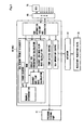
- An exhaust gas purification system 10 shown in Fig. 1 uses urea water solution as reducing agent, and passes exhaust gas through NO x catalyst 13 together with the reducing agent to selectively reduce NO x .
- the exhaust gas purification system 10 has a NO x catalyst 13 which is disposed at some point of an exhaust gas passage 11 connected to an internal combustion engine and selectively reduces NO x contained in exhaust gas, and a reducing agent supply device 20 containing a reducing agent injection valve 31 for injecting reducing agent into the exhaust gas passage 11 at the upstream side of the NO x catalyst 13.
- Temperature sensors 15 and 16 are disposed at the upstream side and the downstream side of the NO x catalyst 13 of the exhaust gas passage 11 respectively, and also an NO x sensor 17 as downstream-side NO x concentration calculating means is disposed at the downstream side of the NO x catalyst 13.
- the constructions of the NO x catalyst 13, the temperature sensors 15, 16 and the NO x sensor 17 are not limited to specific ones, and well-known members may be used.
- At least the NO x sensor 17 has a trouble diagnosis function for the sensor itself, and outputs error information to CAN (Controller Area Network) 65 described later when an abnormal state is detected.
- CAN Controller Area Network
- the reducing agent supply device 20 has an injection module 30 containing a reducing agent injection valve 31, a storage tank 50 in which reducing agent is stocked, a pump module 40 containing a pump 41 for pressure-feeding the reducing agent in the storage tank 50 to the reducing agent injection valve 31, and a control unit (hereinafter referred to as "DCU: Dosing Control unit") 60 for controlling the injection module 30 and the pump module 40 to control the injection amount of the reducing agent to be injected from the reducing agent injection valve 31.
- DCU Dosing Control unit
- the storage tank 50 and the pump module 40 are connected to each other through a first supply passage 57, the pump module 40 and the injection module 30 are connected to each other through a second supply passage 58, and the injection module 30 and the storage tank 50 are connected to each other through a circulation passage 59.
- DCU 60 is connected to CAN 65.
- CAN 65 is connected to a control unit (hereinafter referred to as "ECU: Engine Control Unit” in some cases) 70 for controlling the operation state of the internal combustion engine.
- ECU Engine Control Unit
- CAN 65 it can be determined whether an input signal value is within a standard range or not in CAN 65.
- DCU 60 connected to CAN 65 can read information on CAN 65, and also output information onto CAN 65.
- ECU 70 and DCU 60 comprise separate control units, and can communicate information with each other through CAN 65.
- ECU 70 and DCU 60 may be constructed as a single control unit.
- the storage tank 50 is provided with a temperature sensor 51 for detecting the temperature of reducing agent in the tank, a level sensor 55 for detecting the residual amount of reducing agent and a quality sensor 53 for detecting quality such as viscosity, concentration, etc. of reducing agent. Values detected by these sensors are output as signals and written onto CAN 65. Well-know parts may be properly used as these sensors.
- Urea water solution, hydro carbon (HC) is mainly used as the reducing agent to be stocked, and the exhaust gas purification system of this embodiment is constructed to use urea water solution.
- the pump module 40 has a pump 41, a pressure sensor 43 as pressure detecting means for detecting the pressure in the second supply passage 58 at the downstream of the pump 41 (hereinafter referred to as "pressure of reducing agent" in some cases), a temperature sensor 45 for detecting the temperature of reducing agent to be pressure-fed, a foreign material collecting filter 47 disposed at some position of the second supply passage 58 at the downstream side of the pump 41, and a pressure control valve 49 for returning a part of the reducing agent from the downstream side of the pump 41 to the upstream side of the pump 41 to reduce the pressure when the pressure of the reducing agent at the downstream side of the pump 41 exceeds a predetermined value.
- the pump 41 comprises an electrically-operated pump, for example, and it is driven on the basis of a signal transmitted from DCU 60.
- Well-known sensors may be arbitrarily used as the pressure sensor 43 and the temperature sensor 45. Values detected by these sensors are output as signals, and written onto CAN 65.
- a well-known check valve or the like may be used as the pressure control valve 49.
- the injection module 30 has a pressure chamber 33 in which reducing agent pressure-fed from the pump module 40 side is stocked, a reducing agent injection valve 31 connected to the pressure chamber 33, an orifice 35 disposed at some position of a passage extending from the pressure chamber 33 and intercommunicating with the circulation passage 59, and a temperature sensor 37 disposed just before the orifice 35.
- the reducing agent injection valve 31 comprises an ON-OFF valve for controlling ON-OFF of valve opening through duty control, for example. Furthermore, in the pressure chamber 33, the reducing agent pressure-fed from the pump module 40 is stocked under a predetermined pressure, and the reducing agent is injected into the exhaust gas passage 11 when the reducing agent injection valve 31 is opened on the basis of a control signal transmitted from DCU 60.
- the orifice 35 is disposed in the passage at the downstream side of the pressure chamber 33, so that the internal pressure of the pressure chamber 33, and the second supply passage 58 at the upstream side of the orifice 35 is not lowered easily, and thus the output of the pump module 40 can be suppressed to a low value.
- a valve for performing circulation control of reducing agent may be provided at some position of the circulation passage 59 in place of arranging the orifice 35.
- the circulation passage 59 disposed between the injection module 30 and the storage tank 50 is provided so that reducing agent other than reducing agent injected from the reducing agent injection valve 31 of the injection module 30 is made to reflow into the storage tank 50 out of reducing agent pressure-fed from the pump module 40 in order to prevent the reducing agent from being affected by exhaust gas heat or the like and exposed to high temperature.
- DCU 60 performs the operation control of the reducing agent injection valve 31 on the basis of various information existing on CAN 65 so that a proper amount of reducing agent is injected into the exhaust gas passage 11. Furthermore, DCU 60 in the embodiment of the present invention has a function as a trouble diagnosis device for an NO x sensor 17 (hereinafter referred to as "trouble diagnosis device").
- DCU 60 mainly comprises a microcomputer having a well-known construction, and in Fig. 1 , constructions represented by functional blocks are shown with respect to parts concerning the operation control of the reducing agent injection valve 31, the driving control of the pump 41 and the trouble diagnosis of the exhaust gas purification system 10.
- DCU 60 in the embodiment of the present invention comprises, as main constituent elements, a CAN information taking and generating unit (represented as “CAN information take-out and generation” in Fig. 1 ), a trouble diagnosis unit of the NO x sensor 17 (represented as “NO x sensor trouble diagnosis” in Fig. 1 ), a pump driving control unit (represented as “pump driving control” in Fig. 1 ), a reducing agent injection valve operation controller (represented as “Udv operation control” in Fig. 1 ), etc. Specifically, these parts are implemented by executing programs through the microcomputer (not shown).
- the CAN information taking and generating unit reads information concerning the driving state of the engine output from ECU 70, sensor information output from the NO x sensor 17 and information existing on CAN 65, and outputs these information onto the respective parts.
- the pump driving controller continually reads information concerning the pressure of reducing agent in the second supply passage 58 which is output from the CAN information taking and generating unit, and executes feedback control on the pump 41 on the basis of the pressure information, so that the pressure of the reducing agent in the second supply passage 58 and the pressure chamber 33 is kept to a substantially fixed state.
- the pump 41 is an electrically-operated pump
- the pump 41 when the output pressure value is lower than a target value, the pump 41 is controlled so that the duty ratio of the electrically-operated pump is increased to increase the pressure.
- the pump 41 is controlled so that the duty ratio of the electrically-operated pump is reduced to lower the pressure.
- the reducing agent injection valve operation controller reads the information concerning the reducing agent in the storage tank 50, the information concerning the exhaust gas temperature, the NO x catalyst temperature and the NO x concentration at the downstream side of the NO x catalyst, the information concerning the operation state of the engine, etc. which are output from the CAN information taking and generating unit, generates a control signal for injecting from the reducing agent injection valve 31 reducing agent whose amount is required to reduce NO x contained in exhaust gas, and outputs the control signal to a reducing agent injection valve operation device (represented by "Udv operation device" in Fig. 1 ) 67 for operating the reducing agent injection valve 31.
- a reducing agent injection valve operation device represented by "Udv operation device" in Fig. 1
- the reducing agent in the storage tank 50 is pumped up by the pump 41, and pressure-fed to the injection module 30 side.
- the detection value of the pressure sensor 45 at the downstream side of the pump 41 provided to the pump module 40 is fed back.
- the output of the pump 41 is increased.
- the pressure value exceeds a predetermined value the pressure is reduced by the pressure control valve 49. Accordingly, the pressure of the reducing agent pressure-fed to the injection module 30 side is controlled to be kept to a substantially fixed value.
- the reducing agent pressure-fed from the pump module 40 to the injection module 30 flows into the pressure chamber 33 of the reducing agent and it is kept to substantially fixed pressure, whereby the reducing agent is injected into the exhaust gas passage 11 at all times when the reducing agent injection valve 31 is opened. Furthermore, the reducing agent reflows through the circulation passage 59 into the storage tank 50.
- the reducing agent which is not injected into the exhaust gas passage 11 is stocked in the pressure chamber 33, and thus it is prevented from being exposed to high temperature with exhaust gas heat.
- DCU 60 determines the amount of reducing agent to be injected on the basis of information such as the operation state and exhaust gas temperature of the internal combustion engine, the temperature of the NO x catalyst 13 and the amount of NO x which is passed through the NO x catalyst 13 without being reduced and measured at the downstream side of the NO x catalyst 13, etc., generates the control signal corresponding to the determined reducing agent amount and outputs the control signal to the reducing agent injection valve control device 67.
- the duty control of the reducing agent injection valve 31 is performed by the reducing agent injection valve operation device 67, and a proper amount of reducing agent is injected into the exhaust gas passage 11.
- the reducing agent injected into the exhaust gas passage 11 flows into the NO x catalyst 13 while mixed in the exhaust gas, and used for the reductive reaction of NO x contained in the exhaust gas, whereby the purification of the exhaust gas is performed.
- the NO x sensor as a diagnosis target of the trouble diagnosis device described later is disposed at the downstream side of the NO x catalyst.
- the diagnosis target is not limited to the NO x sensor disposed at this position, and it may be an NO x sensor disposed at the upstream side of the NO x catalyst.
- DCU 60 of the embodiment according to the present invention is provided with a trouble diagnosis unit for the NO x sensor 17.
- the trouble diagnosis unit for the NO x sensor 17 is configured so as to determine whether the NO x sensor 17 accurately responds in a normal operation mode without forcedly creating a diagnosis mode.
- the trouble diagnosis unit for the NO x sensor 17 contains exhaust gas mass flow rate calculating means for calculating the mass flow rate of exhaust gas (represented as “exhaust gas flow rate calculation” in Fig. 2 ), exhaust NO x concentration calculating means for calculating the NO x concentration at the upstream side of the NO x catalyst (represented as “exhaust NO x concentration calculation” in Fig. 2 ), exhaust NO x flow rate calculating means for calculating the NO x flow rate at the upstream side of the NO x catalyst per unit time (represented as “exhaust NO x flow rate calculation" in Fig.
- RAM Random Access Memory
- trouble determining means for determining by using a predetermined reference pattern and a follow pattern whether the detected NO x concentration undergoes a transition while following variation of the exhaust NO x flow rate, thereby determining the responsiveness of the NO x sensor (represented as "trouble determination" in Fig. 2 ).
- the exhaust gas mass flow rate calculating means reads information concerning the operation state of the internal combustion engine which is output from the CAN information taking and generating unit, and calculates the flow rate of the exhaust gas discharged from the internal combustion engine.
- the exhaust NO x concentration calculating means reads information concerning the operation state of the internal combustion state which is output from the CAN information taking and generating unit, and calculates the NO x concentration exhausted from the internal combustion engine.
- the information concerning the operation state of the internal combustion engine which exists on CAN and is used to calculate the exhaust gas mass flow rate and calculate the NO x concentration exhausted from the internal combustion engine contains a fuel injection amount, a rotational number, the status of an exhaust gas circulating device (hereinafter referred to as "EGR: Exhaust Gas Recirculation”), an exhaust circulation amount, an air suction amount, a cooling water temperature, etc.
- EGR Exhaust Gas Recirculation
- the exhaust gas mass flow rate and the exhaust NO x concentration can be calculated on the basis of these information by a well-known method.
- the exhaust NO x flow rate calculating means calculates the exhaust NO x flow amount exhausted from the internal combustion engine per unit time on the basis of the NO x concentration calculated by the exhaust NO x concentration calculating means and the mass flow rate of the exhaust gas calculated by the exhaust gas mass flow rate calculating means.
- RAM stores the exhaust NO x flow amount per unit time which is output from the exhaust NO x flow rate calculating means and the detected NO x concentration of the NO x sensor which is output from the CAN information taking and generating unit, and outputs these information to the trouble determining means described later for use of the trouble determination.
- the trouble determining means reads the exhaust NO x flow rate and the detected NO x concentration stored in RAM, and determines whether the detected NO x concentration undergoes a transition while having a predetermined relation with a follow pattern which is defined in advance when the exhaust NO x flow rate undergoes a transition while having a predetermined relation with a reference pattern which is defined in advance, thereby determining the responsiveness of the NO x sensor. That is, in order to perform a trouble diagnosis for the NO x sensor, the trouble diagnosis device of this invention does not forcedly increase the exhaust NO x flow amount to create a diagnosis mode, but detects the time-lapse variation of the exhaust NO x flow rate suitable for diagnosis in a normal operation mode and determines whether the NO x sensor responds with following this variation.
- any control means having a function of controlling the operation state so that the exhaust NO x concentration of the internal combustion engine is increased to perform the trouble diagnosis of the NO x sensor.
- the trouble determining means is shifted to a determination mode when the exhaust NO x flow rate to be compared by the exhaust NO x flow rate transition comparing means is set to satisfy a predetermined condition with respect to the reference pattern.
- the trouble determining means of this embodiment also has a function of determining that the NO x sensor is firmly fixed due to soot or the like in the exhaust gas when there appears no variation following the detected NO x concentration although a predetermined time elapses from transit variation of the exhaust NO x flow rate.
- the trouble diagnosis unit of this embodiment is provided with a timer counter for counting the time when the trouble diagnosis is performed.
- the reference pattern contains a constant region (pre-stage constant region), a slope region and a post-stage constant region.
- the reference pattern contains a delay region in which the start position of the slope region is delayed by a timer 3.
- the follow pattern contains a follow ramp region and a follow post-stage constant region.
- the exhaust NO x flow rate Nfu which is continually stored in RAM and the detected NO x concentration Nd are continually read out, and a timer 1 is actuated at a time point of t1 at which the value of the exhaust NO x flow rate Nfu dips from the reference value MIN of the constant region of the reference pattern.
- the processing is set to a standby state from a time point of t2 at which the timer 1 is finished under the state that the exhaust NO x flow rate Nfu is lower than the reference value MIN, and it continues to be on standby until the exhaust NO x flow rate Nfu exceeds the reference value MIN.
- another timer may be actuated simultaneously with the timer 1 to determine the maximum time of the standby state, and the diagnosis may be finished when the exhaust NO x flow rate Nfu does not exceed the reference value MIN until a predetermined time elapses. In this case, it can be avoided that an unstable state that a diagnosis program does not operate is continued for a long time.
- a timer 2, a timer 3, a timer 5 and a timer 6 are actuated at a time point of t3 at which the exhaust NO x flow rate Nfu exceeds the reference value MIN, and also the value of the detected NO x concentration at the time point of t3 is stored as Nd 0 . That is, at t3, the trouble determining means is shifted to the determination mode, and also the start position of the follow ramp region of the follow pattern is set to Nd 0 .
- the comparison between the value of the exhaust NO x flow rate Nfu and the value of the reference pattern is not performed during the time period from t3 till a time point of t4 at which the timer 3 is finished, and the time point of t4 is set to the start position of the slope region of the reference pattern.
- the detected NO x concentration Nd With respect to the detected NO x concentration Nd, subsequently to the time point of t3, when the timer 5 actuated at t3 is finished at the time point of t6, it is determined whether the detected NO x concentration Nd is larger than the value Ramp of the follow ramp region and the value max of the follow post-stage constant region until the time when the timer 4 is finished. If the detected NO x concentration Nd indicates a value larger than the value Ramp of the follow ramp region and the value max of the follow post-stage constant region until the timer 4 is finished after the timer 5 is finished, it is determined that the NO x sensor responds while following the transit variation of the exhaust NO x flow rate Nfu.
- the detected NO x concentration Nd is lower than the value Ramp of the follow ramp region and the value max of the follow post-stage constant region until the timer 4 is finished after the timer 5 is finished, it is determined that some abnormality occurs in the responsiveness of the NO x sensor.
- the timer 6 is actuated at the time point of t3, and when the detected NO x concentration Nd does not vary from the start value Ndo as a criteria by a stipulated value ABS or more until t7 at which the timer 6 is finished, it is determined that the NO x sensor is firmly fixed due to soot or the like in the exhaust gas.
- the value of the stipulated value ABS is set as a criteria to determine the fixing of the NO x sensor.
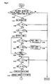
- This routine may be executed at all times, or may be executed by interruption every constant time.
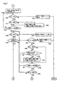
- step S100 it is determined in step S100 whether there is no error information from the NO x sensor provided at the downstream side of the NO x catalyst and also an input value from the NO x sensor is within a standard range of CAN. When these conditions are not satisfied, the processing is returned to the start position. When all the conditions are satisfied, the processing goes to step S101.
- step S101 a detection signal Ns from the NO x sensor is recognized, and then it is determined in step S102 in combination with the condition determined in step S100 whether the engine speed is equal to or more than a stipulated value and also an exhaust brake is set to OFF (hereinafter referred to as "test environment condition (TE)"). When these conditions are not satisfied, the processing is returned to the start position. When all the conditions are satisfied, the processing goes to step S103.
- TE test environment condition
- step S103 the exhaust NO x flow rate Nfu is read, and it is determined whether the exhaust NO x flow rate Nfu is less than the stipulated value MIN.
- the processing is returned to the start position.
- the processing goes to step S104.
- step S104 executed when the exhaust NO x flow rate Nfu is less than the stipulated value MIN, the timer 1 is actuated, and the processing goes to step S105.
- step S105 it is determined whether the above test environment condition is satisfied. When the test environment condition is not satisfied, the timer 1 is reset in step S106, and then the processing is returned to the start position. When the test environment condition is satisfied, the processing goes to step S107.
- step S107 it is determined whether the exhaust NO x flow rate Nfu is less than the reference value MIN of the first constant region of the reference pattern.
- the timer 1 is reset in step S108, and then the processing is returned to the start position.
- the processing goes to step S109 to determine whether the timer 1 is finished.
- the processing is returned to step S105.
- the processing goes to step S110.
- step S110 to which the processing goes when the time period of the timer 1 is finished under the state that the exhaust NO x flow rate Nfu is less than the value MIN, it is determined again whether the test environment condition is satisfied. When the test environment condition is not satisfied, the processing is returned to the start position. On the other hand, when the test environment condition is satisfied, the processing goes to step S111 to determine whether the exhaust NO x flow rate Nfu is equal to or more than the value MIN. When the exhaust NO x flow rate Nfu is less than the value MIN, the processing is returned to step S110.
- step S112 when the exhaust NO x flow rate Nfu is equal to or more than the value MIN, the processing goes to step S112 to store, as the start value Nd 0 , the value Nd of the detected NO x concentration detected by the NO x sensor at this time point, and also goes to step S113 to actuate the timers 2, 3, 5 and 6.
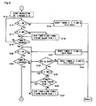
- step S114 the calculation of the absolute value D of the difference between the value of the detected NO x concentration Nd of the NO x sensor and the stored start value Nd 0 is started.
- step S115 it is determined whether the test environment condition is satisfied. When it is not satisfied, all the timers 2, 3, 5 and 6 are reset in step S116, and then the processing is returned to the start position. On the other hand, when the test environment condition is satisfied, it is determined whether the absolute value D calculated through the calculation of the step S117 is less than the stipulated value ABS.
- step S119 When the absolute value D is less than the stipulated value ABS, the processing directly goes to step S119, and when the absolute value D is equal to or more than the stipulated value ABS, the timer 6 is stopped in step S118, and the processing goes to step S119 after the firm fixing TestOK flag is erected.
- step S119 it is determined in step S119 whether the timer 3 is finished or not.
- the processing is returned to step S115.
- step S120 it is determined whether the test environment condition is satisfied or not.
- the timers 2, 5 and 6 are reset in step S121, and then the processing is returned to the start position.
- step S122 it is determined whether the timer 2 is finished or not.
- step S123 it is determined in step S123 whether the exhaust NO x flow rate Nfu is equal to or more than the value SLOPE of the slope region of the reference pattern.
- the processing goes to step S124 to reset the timers 2, 5 and 6, and then the processing is returned to the start position.
- step S125 when the exhaust NO x flow rate Nfu is equal to or more than the value SLOPE, the processing goes to step S125, and it is determined whether the absolute value D of the difference between the detected NO x concentration Nd and the start value Nd 0 is less than the stipulated value ABS.
- the processing is directly returned to step S120.
- step S126 when the absolute value D is equal to or more than the stipulated value ABS, it is determined in step S126 whether the firmly fixing TestOK flag is put up. When the firmly fixing TestOK flag is put up, the processing is directly returned to step S120.
- the timer 6 is stopped and also the firmly fixing TestOK flag is put up in step S127, and then the processing is returned to step S120.
- step S122 When the timer 2 is finished in step S122, the timer 4 is actuated in step S128, and it is determined in step S129 whether the test environment condition is satisfied. When the test environment condition is not satisfied, the timers 4, 5 and 6 are reset in step S130, and then the processing is returned to the start position. On the other hand, when the test environment condition is satisfied, the processing goes to step S131 to determine whether the exhaust NO x flow rate Nfu is equal to or more than the value MAX of the post-stage constant region of the reference pattern. When the exhaust NO x flow rate Nfu is less than the value MAX, the timers 4, 5 and 6 are reset in step S132, and then the processing is returned to the start position.
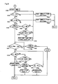
- step S133 determines whether the timer 5 is finished.
- step S134 determines whether the absolute value D is less than the stipulated value ABS.
- step S134 when the absolute value D is less than the stipulated value ABS, the processing is directly returned to step S129 as in the case of the step S125.
- step S135 it is determined in step S135 whether the firmly fixing TestOK flag is put up.
- the processing is directly returned to step S129.
- the timer 6 is stopped in step S136, the firmly fixing TestOK flag is put up, and then the processing is returned to step S129.
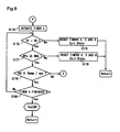
- step S133 the processing goes to step S137 to determine whether the detected NO x concentration Nd is equal to or more than the value Ramp of the follow ramp region of the follow pattern or the value max of the follow post-stage constant region.
- step S138 it is further determined in step S138 whether the absolute value D is less than the stipulated value ABS.
- responsiveness TestError is determined because it is determined that the NO x sensor is not firmly fixed, but the NO x sensor does not properly follow the variation of the exhaust NO x flow rate, and then the diagnosis is finished.
- step S139 determines whether the firmly fixing TestOK flag is put up.
- responsiveness TestError is determined because it is determined that the NO x sensor is not firmly fixed, but it does not properly follow the variation of the exhaust NO x flow rate, and then the diagnosis is finished.
- step S140 it is determined in step S140 whether the timer 6 is finished or not.
- firmly fixing TestError is determined because it is determined that the NO x sensor hardly responds although a predetermined time elapses, and then the diagnosis is finished.
- the processing goes to step S141 to determine whether the test environment condition is satisfied or not. When it is satisfied, the processing is returned to step S138.
- step S142 determines whether the timer 4 is finished or not.
- the processing is returned to step S137.
- TestOK is determined because the NO x sensor is not firmly fixed, and it properly follows the variation of the exhaust NO x flow rate, and the diagnosis is finished.
- the time elapsing until the start position of the follow ramp region of the follow pattern (the lapse time of the timer 5) is set to be longer than the time elapsing until the slope region of the reference pattern is finished (the lapse time of the timer 2).
- the trouble diagnosis method for the NO x sensor in the SCR system in which the capacity of the NO x catalyst disposed in the exhaust gas passage is large such as a large-size vehicle or the like has been described in this embodiment, and the time period from the time when the exhaust NO x flow rate increases to the time when the detected NO x flow rate detected by the NO x sensor disposed at the downstream side of the NO x catalyst follows the increase concerned is longer by the amount corresponding to the increase of the capacity of the NO x catalyst.
- the setting of the lapse times of the timer 2 and the timer 5 may be arbitrarily set in accordance with the follow-up performance of the NO x sensor at the downstream side of the NO x catalyst, and a NO x sensor trouble diagnosis method in an SCR system in which the capacity of the NO x catalyst is relatively small will be described in a second embodiment.
- the NO x sensor trouble diagnosis method is an NO x sensor trouble diagnosis method in an SCR system in which the capacity of the NO x catalyst is relatively small as described above. That is, in this embodiment, the time period from the time when the exhaust NO x flow rate increases till the time when the detected NO x flow rate detected by the NO x sensor disposed at the downstream side of the NO x catalyst follows is short, and the lapse time of the timer 2 is set to be longer than the lapse time of the timer 5.
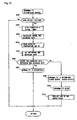
- points different from those of the first embodiment will be mainly described along the flowcharts of Figs. 7 to 9 .
- steps S100 to S113 as the first embodiment are executed until the timers 2, 3, 5 and 6 are actuated (see Fig. 4 ).
- steps S154 to S161 are executed as in the case of the steps S114 to S121 of the first embodiment (see Fig. 5 ), and then the processing goes to step S162.
- step S162 it is determined whether the timer 2 is finished. When the timer 2 is not finished, it is determined in step S163 whether the exhaust NO x flow rate Nfu is equal to or more than the value SLOPE of the slope region of the reference pattern. When the exhaust NO x flow rate Nfu is less than SLOPE, the processing goes to step S164 to reset the timers 2, 5 and 6, and then the processing is returned to the start position.
- step S165 determines whether the absolute value D of the difference between the detected NO x concentration Nd and the start value Ndo is less than the stipulated value ABS.
- the processing directly goes to step S168.
- step S166 determines whether the firmly fixing TestOK flag is put up.
- the processing directly goes to step S168.
- the timer 6 is stopped and the firmly fixing TestOK flag is put up in step S167, and then the processing goes to step S168.
- step S168 it is determined whether the timer 5 is finished.
- the processing is returned to step S160.
- step S169 it is determined whether the detected NO x concentration Nd is equal to or more than the value Ramp of the follow ramp region of the follow pattern.
- the processing is returned to step S160.
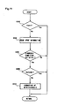
- step S170 it is determined in step S170 whether the absolute value D is less than the stipulated value ABS.
- the responsiveness TestError is determined because it is determined that the NO x sensor is not firmly fixed, but it does not properly follow the variation of the exhaust NO x flow rate, and then the diagnosis is finished.
- the processing goes to step S171 to determine whether the firmly fixing TestOK flag is put up.
- the responsiveness TestError is determined because it is determined that the NO x sensor is not firmly fixed, but it does not properly follow the variation of the exhaust NO x flow rate, and then the diagnosis is finished.
- step S172 it is determined in step S172 whether the timer 6 is finished.
- the firmly fixing TestError is determined because it is determined that the NO x sensor hardly responds although a predetermined time elapses, and thus the diagnosis is finished.
- the processing goes to step S173 to determine whether the test environment condition is satisfied.
- the processing is returned to step S170.
- it is processed as the responsiveness TestError because the NO x sensor gets out of the test environment condition under the state that it has not yet led to the determination of the firm fixing, and thus the diagnosis is finished.
- step S162 When the timer 2 is finished in step S162, the timer 4 is actuated in step S174, and also it is determined in step S175 whether the test environment condition is satisfied. When the test environment condition is not satisfied, the timers 4, 5 and 6 are reset in step S176, and then the processing is returned to the start position. On the other hand, when the test environment condition is satisfied, the processing goes to step S177 to determine whether the exhaust NO x flow rate Nfu is equal to or more than the value MAX of the post-stage constant region of the reference pattern. When the exhaust NO x flow rate Nfu is less than the value MAX, the timers 4, 5 and 6 are reset in step S178, and the processing is returned to the start position.
- step S179 determines whether the detected NO x concentration Nd is equal to or more than the value Ramp of the follow ramp region of the follow pattern or the value max of the follow post-stage constant region of the follow pattern.
- step S180 determines whether the timer 4 is finished.
- the processing is returned to step S175.
- TestOK is determined because it is determined that the NO x sensor is not firmly fixed and it properly follows the variation of the exhaust NO x flow rate.
- step S170 the processing goes to step S170 as in the case described above, and it is determined whether the absolute value D is less than the stipulated value ABS.
- the absolute value D is equal to or more than the stipulated value ABS
- the responsiveness TestError is determined because it is determined that the NO x sensor is not firmly fixed, but it does not properly follow the variation of the exhaust NO x flow rate, and the diagnosis is finished.
- the processing goes to step S171 to determine whether the firmly fixing TestOK flag is put up.
- the responsiveness TestError is determined because it is determined that the NO x sensor is not firmly fixed, but it does not properly follow the variation of the exhaust NO x flow rate, and thus the diagnosis is finished.
- step S172 it is determined in step S172 whether the timer 6 is operated.
- the firmly fixing TestError is determined because it is determined that the NO x sensor hardly responds even when a predetermined time elapses, and thus the diagnosis is finished.
- the processing goes to step S173 to determine whether the test environment condition is satisfied.
- the processing is returned to step S170.
- it is processed as the responsiveness TestError because it is determined that the NO x sensor gets out of the test environment condition under the state that it has not yet led to the determination of the firm fixing, and thus the diagnosis is finished.
- the NO x sensor trouble diagnosis can be performed on a timely basis in the normal operation state without intentionally creating any diagnosis mode. Accordingly, the responsiveness of the NO x sensor can be determined without deteriorating the drivability and the fuel consumption.
- the construction of the exhaust gas purification system is an example, and the exhaust gas purification system that can implement the NO x sensor trouble diagnosis method of the present invention is not limited to the thusconstructed exhaust gas purification system.
- CAN may be omitted, and DCU may be constructed integrally with the engine ECU.
- the exhaust gas purification system may be constructed so that the circulation passage provided for the purpose of the temperature control of reducing agent is omitted.
Landscapes
- Engineering & Computer Science (AREA)
- Chemical & Material Sciences (AREA)
- Combustion & Propulsion (AREA)
- General Engineering & Computer Science (AREA)
- Mechanical Engineering (AREA)
- Chemical Kinetics & Catalysis (AREA)
- Health & Medical Sciences (AREA)
- Environmental & Geological Engineering (AREA)
- Biomedical Technology (AREA)
- Oil, Petroleum & Natural Gas (AREA)
- General Chemical & Material Sciences (AREA)
- Analytical Chemistry (AREA)
- Toxicology (AREA)
- Exhaust Gas After Treatment (AREA)
- Combined Controls Of Internal Combustion Engines (AREA)
- Exhaust Gas Treatment By Means Of Catalyst (AREA)
- Electrical Control Of Air Or Fuel Supplied To Internal-Combustion Engine (AREA)
- Measuring Oxygen Concentration In Cells (AREA)
Claims (9)
- NOx-Sensor-Fehlerdiagnosevorrichtung, die in einem Abgaskanal (11) einer Brennkraftmaschine vorgesehen ist und die Konzentration von NOx im Abgas, das sich durch den Abgaskanal bewegt, detektiert, wobei die Vorrichtung umfasst:Abgas-NOx-Durchflussmengen-Berechnungs- und -Speichermittel, um eine Abgas-NOx-Durchflussmenge, die von der Brennkraftmaschine pro Zeiteinheit ausgestoßen wird, zu berechnen und zu speichern;Mittel zum Speichern der detektierten NOx-Konzentration, um eine durch einen NOx-Sensor (17) detektierte NOx-Konzentration zu speichern;dadurch gekennzeichnet, dass sie ferner umfasst:Fehlerbestimmungsmittel, um ein Referenzmuster als eine Zeitverlaufsveränderungsreferenz der Abgas-NOx-Durchflussmenge und ein Folgemuster als eine Zeitverlaufsveränderungsreferenz der durch den NOx-Sensor (17) detektierten NOx-Konzentration zu definieren und um zu bestimmen, ob die detektierte NOx-Konzentration einen Übergang ausführt, während sie eine vorgegebene Beziehung zu dem Folgemuster hat, wenn die Abgas-NOx-Durchflussmenge einen Übergang ausführt, während sie eine vorgegebene Beziehung zu dem Referenzmuster hat, falls die Brennkraftmaschine in einer normalen Betriebsart ist, um das Ansprechverhalten des NOx-Sensors (17) zu bestimmen.
- NOx-Sensor-Fehlerdiagnosevorrichtung nach Anspruch 1,
wobei das Referenzmuster ein Muster ist, das einen konstanten Bereich, in dem ein erster Referenzwert für eine feste Zeit andauert, und einen Neigungsbereich, in dem der erste Referenzwert mit einer vorgegebenen Zunahmerate zunimmt, enthält,
wobei das Folgemuster ein Muster ist, das einen Folgeneigungsbereich enthält, in dem ein erster Referenzwert mit einer vorgegebenen Zunahmerate zunimmt, wobei die Fehlerbestimmungsmittel bestimmen, ob die detektierte NOx-Konzentration einen Übergang ausführt, so dass sie von dem Wert des Folgerampenbereichs des Folgemusters nicht abfällt, wenn die Abgas-NOx-Strömungsrate einen Übergang ausführt, so dass sie von dem Wert des Neigungsbereichs des Referenzmusters nicht abfällt. - NOx-Sensor-Fehlerdiagnosevorrichtung nach Anspruch 2,
wobei die Fehlerbestimmungsmittel in den Bestimmungsmodus verschoben werden, wenn die Abgas-NOx-Durchflussmenge den Wert eines vorgegebenen Referenzwerts erreicht, nachdem sie für eine feste Zeit oder länger einen Übergang ausgeführt hat, um den vorgegebenen Referenzwert nicht zu überschreiten. - NOx-Sensor-Fehlerdiagnosevorrichtung nach Anspruch 3,
wobei die Fehlerbestimmungsmittel den Wert der detektierten NOx-Konzentration zur Zeit der Verschiebung in den Bestimmungsmodus auf einen Anfangswert des Folgerampenbereichs des Folgemusters einstellen. - NOx-Sensor-Fehlerdiagnosevorrichtung nach Anspruch 3 oder 4, wobei die Fehlerbestimmungsmittel den Bestimmungsmodus anhalten, wenn die Abgas-NOx-Durchflussmenge einen vorgegebenen Referenzwert übersteigt und dann von dem Wert des Neigungsbereichs des Referenzmusters abfällt.
- NOx-Sensor-Fehlerdiagnosevorrichtung nach einem der Ansprüche 2 bis 5, wobei das Referenzmuster einen Verzögerungsbereich besitzt, um die Startposition des Neigungsbereichs um eine vorgegebene Zeit zwischen dem konstanten Bereich und dem Neigungsbereich zu verzögern.
- NOx-Sensor-Fehlerdiagnosevorrichtung nach einem der Ansprüche 2 bis 6, wobei das Referenzmuster einen konstanten Nachstufenbereich enthält, der sich hinter dem Neigungsbereich befindet und in dem ein zweiter Referenzwert, der größer als der erste Referenzwert ist, für eine feste Zeit andauert, wobei das Folgemuster einen konstanten Nachstufen-Folgebereich enthält, der sich hinter dem Folgerampenbereich befindet und in dem ein dritter Referenzwert für eine feste Zeit andauert, und die Fehlerbestimmungsmittel bestimmen, ob die detektierte NOx-Konzentration einen Übergang ausführt, so dass sie nicht von dem Wert des Folgerampenbereichs und dem Wert des konstanten Nachstufen-Folgebereichs des Folgemusters abfällt, wenn die Abgas-NOx-Durchflussmenge einen Übergang ausführt, so dass sie nicht von dem Wert des Neigungsbereichs und dem Wert des konstanten Nachstufenbereichs des Referenzmusters abfällt.
- NOx-Sensor-Fehlerdiagnosevorrichtung nach einem der Ansprüche 2 bis 7, wobei die Fehlerbestimmungsmittel eine stabil feste Stufe des NOx-Sensors (17) bestimmen, in der der NOx-Sensor (17) nicht auf NOx-Schwankungen aufgrund von Ruß oder dergleichen reagiert, indem sie bestimmen, ob eine vorgegebene Zeit in dem Zustand, in dem die detektierte NOx-Konzentration nicht um einen vorgegebenen Wert oder mehr in Bezug auf den Wert hiervon zunimmt, verstrichen ist oder nicht, wenn die Abgas-NOx-Durchflussmenge den ersten Referenzwert übersteigt.
- Fehlerdiagnoseverfahren für einen NOx-Sensor (17), der in einem Abgaskanal (11) einer Brennkraftmaschine vorgesehen ist und die Konzentration von NOx im Abgas, das sich durch den Abgaskanal (11) bewegt, detektiert, dadurch gekennzeichnet, dass das Verfahren umfasst:im Voraus Einstellen eines Referenzmusters als ein Kriterium für eine Zeitverlaufsveränderung der Durchflussmenge von Abgas-NOx, das von einer Brennkraftmaschine ausgestoßen wird, und eines Folgemusters als ein Kriterium für eine Zeitverlaufsveränderung der detektierten NOx-Konzentration, die durch den NOx-Sensor (17) detektiert wird; undBestimmen des Ansprechverhaltens des NOx-Sensors (17) durch Bestimmen, ob die detektierte NOx-Konzentration einen Übergang ausführt, während sie eine vorgegebene Beziehung zu dem Folgemuster hat, wenn die Abgas-NOx-Durchflussmenge einen Übergang ausführt, während sie eine vorgegebene Beziehung zu dem Referenzmuster hat.
Applications Claiming Priority (2)
| Application Number | Priority Date | Filing Date | Title |
|---|---|---|---|
| JP2007024213A JP4297379B2 (ja) | 2007-02-02 | 2007-02-02 | Noxセンサの故障診断装置及び故障診断方法 |
| PCT/JP2008/051059 WO2008093607A1 (ja) | 2007-02-02 | 2008-01-25 | Noxセンサの故障診断装置及び故障診断方法 |
Publications (3)
| Publication Number | Publication Date |
|---|---|
| EP2128396A1 EP2128396A1 (de) | 2009-12-02 |
| EP2128396A4 EP2128396A4 (de) | 2010-03-10 |
| EP2128396B1 true EP2128396B1 (de) | 2011-08-24 |
Family
ID=39673919
Family Applications (1)
| Application Number | Title | Priority Date | Filing Date |
|---|---|---|---|
| EP08703886A Active EP2128396B1 (de) | 2007-02-02 | 2008-01-25 | Störungsdiagnosevorrichtung und störungsdiagnoseverfahren für einen nox-sensor |
Country Status (7)
| Country | Link |
|---|---|
| US (1) | US8359826B2 (de) |
| EP (1) | EP2128396B1 (de) |
| JP (1) | JP4297379B2 (de) |
| KR (1) | KR101088316B1 (de) |
| CN (1) | CN101600863B (de) |
| AT (1) | ATE521796T1 (de) |
| WO (1) | WO2008093607A1 (de) |
Families Citing this family (47)
| Publication number | Priority date | Publication date | Assignee | Title |
|---|---|---|---|---|
| DE102007006489B4 (de) * | 2007-02-09 | 2018-10-04 | Robert Bosch Gmbh | Verfahren zur Diagnose eines in einem Abgasbereich einer Brennkraftmaschine angeordneten Abgassensors und Vorrichtung zur Durchführung des Verfahrens |
| JP5152912B2 (ja) * | 2008-06-27 | 2013-02-27 | ボッシュ株式会社 | タンク内センサの合理性診断方法及び合理性診断装置 |
| JP2010101860A (ja) * | 2008-10-27 | 2010-05-06 | Mitsubishi Motors Corp | 車両に搭載された機構の故障診断装置 |
| WO2010109946A1 (ja) * | 2009-03-23 | 2010-09-30 | ボッシュ株式会社 | Noxセンサの合理性診断装置及び合理性診断方法 |
| JP4874364B2 (ja) * | 2009-04-14 | 2012-02-15 | 株式会社日本自動車部品総合研究所 | 内燃機関の排気浄化装置 |
| US9354618B2 (en) | 2009-05-08 | 2016-05-31 | Gas Turbine Efficiency Sweden Ab | Automated tuning of multiple fuel gas turbine combustion systems |
| US8437941B2 (en) * | 2009-05-08 | 2013-05-07 | Gas Turbine Efficiency Sweden Ab | Automated tuning of gas turbine combustion systems |
| US9671797B2 (en) | 2009-05-08 | 2017-06-06 | Gas Turbine Efficiency Sweden Ab | Optimization of gas turbine combustion systems low load performance on simple cycle and heat recovery steam generator applications |
| US9267443B2 (en) | 2009-05-08 | 2016-02-23 | Gas Turbine Efficiency Sweden Ab | Automated tuning of gas turbine combustion systems |
| WO2010134167A1 (ja) * | 2009-05-19 | 2010-11-25 | トヨタ自動車株式会社 | NOxセンサの異常診断装置 |
| DE112010002699B4 (de) | 2009-06-24 | 2023-11-09 | Cummins Ip, Inc. | Vorrichtung, System und Verfahren zur Abschätzung der Verschlechterung des Ansprechverhaltens elnes NOx-Sensors |
| CN102792140B (zh) * | 2009-12-16 | 2016-01-20 | 康明斯过滤Ip公司 | 诊断NOx传感器的装置和方法 |
| JP5789925B2 (ja) * | 2010-07-08 | 2015-10-07 | いすゞ自動車株式会社 | NOxセンサ診断装置及びSCRシステム |
| US9121323B2 (en) * | 2011-04-15 | 2015-09-01 | GM Global Technology Operations LLC | Nitrogen oxide sensor stuck-in-range diagnostic tool |
| JP5915111B2 (ja) * | 2011-11-18 | 2016-05-11 | いすゞ自動車株式会社 | NOxセンサの異常診断方法、NOxセンサの異常診断システム、及び内燃機関のNOx排出濃度推定方法 |
| US8924130B2 (en) * | 2012-03-01 | 2014-12-30 | Ford Global Technologies, Llc | Non-intrusive exhaust gas sensor monitoring |
| JP5559230B2 (ja) * | 2012-04-03 | 2014-07-23 | 本田技研工業株式会社 | 内燃機関の排気浄化システム |
| WO2013152780A1 (en) * | 2012-04-10 | 2013-10-17 | Volvo Lastvagnar Ab | A self-diagnosing method for diagnosing a scr system |
| US8910466B2 (en) * | 2012-05-09 | 2014-12-16 | GM Global Technology Operations LLC | Exhaust aftertreatment system with diagnostic delay |
| US9528462B2 (en) * | 2012-06-15 | 2016-12-27 | GM Global Technology Operations LLC | NOx sensor plausibility monitor |
| US9546585B2 (en) * | 2013-02-27 | 2017-01-17 | Cummins Ip, Inc. | Apparatus, method, and system for diagnosing reductant delivery performance |
| SE537270C2 (sv) * | 2013-07-02 | 2015-03-24 | Scania Cv Ab | Anordning och förfarande för detektering av defekt NOx-givare |
| BR112016007377B1 (pt) * | 2013-10-04 | 2022-02-15 | Volvo Truck Corporation | Método para monitorar nox; memória legível por computador e sistema de sensor |
| CN103903412B (zh) * | 2014-03-28 | 2017-04-12 | 哈尔滨工程大学 | 一种用于NOx传感器的CAN总线转4‑20mA的数据信号转换装置 |
| JP6248789B2 (ja) * | 2014-05-08 | 2017-12-20 | いすゞ自動車株式会社 | 排気浄化システム |
| KR101637758B1 (ko) | 2014-12-03 | 2016-07-07 | 현대자동차주식회사 | Scr 시스템의 고장진단방법 및 고장진단장치 |
| NL2015086B1 (en) * | 2015-07-03 | 2017-01-30 | Daf Trucks Nv | Method, apparatus, and system for diagnosing at least one NOx-sensor of a diesel engine system. |
| US10995647B2 (en) | 2015-11-20 | 2021-05-04 | Cummins, Inc. | Systems and methods for using oxygen to diagnose in-range rationality for NOx sensors |
| DE102016202765A1 (de) * | 2016-02-23 | 2017-08-24 | Fraunhofer-Gesellschaft zur Förderung der angewandten Forschung e. V. | Schaltkreisanordnung und Verfahren zum Herstellen einer Schaltkreisanordnung |
| CN107462670A (zh) * | 2016-06-03 | 2017-12-12 | 大陆汽车电子(长春)有限公司 | 氮氧化物传感器故障检测方法 |
| JP6569604B2 (ja) | 2016-06-10 | 2019-09-04 | 株式会社デンソー | 噴射制御装置 |
| CN107035490B (zh) * | 2017-03-29 | 2019-04-12 | 北京航空航天大学 | 一种柴油机scr系统氮氧化物输入传感器故障诊断方法 |
| CN107023367B (zh) * | 2017-03-29 | 2019-04-12 | 北京航空航天大学 | 一种柴油机scr系统氨气输入传感器故障诊断和容错控制方法 |
| CN108150262B (zh) * | 2017-12-22 | 2020-05-22 | 中国第一汽车股份有限公司 | 判断氮氧传感器是否失效的检测方法 |
| US10690078B2 (en) * | 2018-04-25 | 2020-06-23 | International Engine Intellectual Property Company, Llc | System and method for estimating engine exhaust nitrogen oxide sensor instability |
| CN108825344B (zh) * | 2018-06-08 | 2020-12-15 | 无锡威孚力达催化净化器有限责任公司 | 一种NOx传感器测量值合理性判断方法及装置 |
| JP2020060120A (ja) * | 2018-10-09 | 2020-04-16 | 日本碍子株式会社 | 触媒の劣化診断装置及び触媒の劣化診断方法 |
| US11828210B2 (en) | 2020-08-20 | 2023-11-28 | Denso International America, Inc. | Diagnostic systems and methods of vehicles using olfaction |
| US11813926B2 (en) | 2020-08-20 | 2023-11-14 | Denso International America, Inc. | Binding agent and olfaction sensor |
| US11636870B2 (en) | 2020-08-20 | 2023-04-25 | Denso International America, Inc. | Smoking cessation systems and methods |
| US11760169B2 (en) | 2020-08-20 | 2023-09-19 | Denso International America, Inc. | Particulate control systems and methods for olfaction sensors |
| US11932080B2 (en) | 2020-08-20 | 2024-03-19 | Denso International America, Inc. | Diagnostic and recirculation control systems and methods |
| US11760170B2 (en) | 2020-08-20 | 2023-09-19 | Denso International America, Inc. | Olfaction sensor preservation systems and methods |
| US11881093B2 (en) | 2020-08-20 | 2024-01-23 | Denso International America, Inc. | Systems and methods for identifying smoking in vehicles |
| CN112412599B (zh) * | 2020-11-18 | 2022-04-05 | 潍柴动力股份有限公司 | 上游NOx传感器故障识别方法、装置、车辆及存储介质 |
| CN112648055B (zh) * | 2020-12-10 | 2022-01-21 | 潍柴动力股份有限公司 | 氮氧化物传感器的可信性检测方法、装置、设备及介质 |
| US11959433B2 (en) * | 2022-07-19 | 2024-04-16 | Cummins Emission Solutions Inc. | Systems and methods for determining exhibited useful life of sensors in monitored systems |
Family Cites Families (14)
| Publication number | Priority date | Publication date | Assignee | Title |
|---|---|---|---|---|
| JP2827719B2 (ja) * | 1992-07-16 | 1998-11-25 | 三菱自動車工業株式会社 | O2 センサの故障判定方法 |
| JP2962089B2 (ja) * | 1993-03-15 | 1999-10-12 | 日産自動車株式会社 | 内燃機関の触媒劣化診断装置 |
| JP2554836B2 (ja) * | 1993-12-24 | 1996-11-20 | 株式会社東芝 | 脱硝制御装置 |
| JP3134698B2 (ja) | 1995-02-10 | 2001-02-13 | 三菱自動車工業株式会社 | 空燃比センサの劣化診断装置 |
| DE10049685A1 (de) * | 2000-10-07 | 2002-04-11 | Volkswagen Ag | Verfahren und Vorrichtung zur Eigendiagnose eines NOX-Sensors |
| DE10062289A1 (de) * | 2000-12-14 | 2002-07-04 | Siemens Ag | Verfahren zur Diagnose eines NOx-Sensors im Abgastrakt einer Brennkraftmaschine |
| US6453663B1 (en) * | 2001-08-16 | 2002-09-24 | Ford Global Technologies, Inc | NOx sensor monitoring |
| JP3927395B2 (ja) * | 2001-09-28 | 2007-06-06 | 株式会社日立製作所 | 圧縮着火エンジンの制御装置 |
| JP3873788B2 (ja) | 2002-03-18 | 2007-01-24 | トヨタ自動車株式会社 | NOxセンサの故障診断装置 |
| JP4273306B2 (ja) | 2003-03-05 | 2009-06-03 | 三菱ふそうトラック・バス株式会社 | NOxセンサの異常判定装置 |
| JP4232524B2 (ja) * | 2003-04-25 | 2009-03-04 | 株式会社日立製作所 | エンジンの制御装置 |
| US6823843B1 (en) * | 2004-01-13 | 2004-11-30 | Ford Global Technologies, Llc | System and method to minimize the amount of NOx released from a NOx trap |
| DE102004048136A1 (de) * | 2004-10-02 | 2006-04-06 | Robert Bosch Gmbh | Verfahren zur Diagnose eines in einem Abgasbereich einer Brennkraftmaschine angeordneten NOx-Sensors und Vorrichtung zur Durchführung des Verfahrens |
| US7178328B2 (en) * | 2004-12-20 | 2007-02-20 | General Motors Corporation | System for controlling the urea supply to SCR catalysts |
-
2007
- 2007-02-02 JP JP2007024213A patent/JP4297379B2/ja active Active
-
2008
- 2008-01-25 CN CN2008800037244A patent/CN101600863B/zh active Active
- 2008-01-25 WO PCT/JP2008/051059 patent/WO2008093607A1/ja active Application Filing
- 2008-01-25 US US12/525,408 patent/US8359826B2/en active Active
- 2008-01-25 EP EP08703886A patent/EP2128396B1/de active Active
- 2008-01-25 AT AT08703886T patent/ATE521796T1/de not_active IP Right Cessation
- 2008-01-25 KR KR1020097011362A patent/KR101088316B1/ko active IP Right Grant
Also Published As
| Publication number | Publication date |
|---|---|
| JP2008190383A (ja) | 2008-08-21 |
| EP2128396A1 (de) | 2009-12-02 |
| KR101088316B1 (ko) | 2011-12-01 |
| CN101600863A (zh) | 2009-12-09 |
| EP2128396A4 (de) | 2010-03-10 |
| ATE521796T1 (de) | 2011-09-15 |
| JP4297379B2 (ja) | 2009-07-15 |
| CN101600863B (zh) | 2011-12-14 |
| KR20090079973A (ko) | 2009-07-22 |
| US20100031633A1 (en) | 2010-02-11 |
| US8359826B2 (en) | 2013-01-29 |
| WO2008093607A1 (ja) | 2008-08-07 |
Similar Documents
| Publication | Publication Date | Title |
|---|---|---|
| EP2128396B1 (de) | Störungsdiagnosevorrichtung und störungsdiagnoseverfahren für einen nox-sensor | |
| EP2108793B1 (de) | Versagensdiagnosevorrichtung für abgasreinigungssystem und versagensdiagnoseverfahren für abgasreinigungssystem | |
| EP2128395B1 (de) | Verstopfungsbeurteilungsvorrichtung für ein reduktionsmitteleinspritzventil und verstopfungsbeurteilungsverfahren für ein reduktionsmitteleinspritzventil | |
| US8387366B2 (en) | Reducing agent injection valve abnormality detection device and abnormality detection method, and internal combustion engine exhaust gas purification system | |
| US8161735B2 (en) | Clogging determining device for reducing agent passage and clogging determining method for reducing agent passage | |
| US8522530B2 (en) | Reducing agent injection valve abnormality detection device and abnormality detection method | |
| EP2187009B1 (de) | Betriebsverfahren für ein Abgasbehandlungssystem | |
| CN101660456B (zh) | 稀氮氧化物排放控制系统和方法 | |
| EP2317092A1 (de) | Abgasreinigungsvorrichtung für einen Verbrennungsmotor | |
| CN101235741A (zh) | 排放控制诊断系统及方法 | |
| JP2010071195A (ja) | NOxセンサの出力較正装置及び出力較正方法 | |
| CN102027212A (zh) | 氮氧化物排放模型的校正方法 | |
| JP2009156206A (ja) | NOxセンサ異常検出装置およびそれを用いた排気浄化システム | |
| CN114370319B (zh) | 一种scr后处理系统的闭环控制方法及其控制系统 | |
| US11536182B2 (en) | Method and processing unit for ascertaining a catalytic converter state | |
| CN103797222A (zh) | 内燃机的排气净化装置 | |
| US20180171847A1 (en) | Method for Operating an Exhaust Gas Purification System Connected to an Internal Combustion Engine of a Motor-Vehicle Comprising an SCR Catalyst | |
| KR20190074394A (ko) | 선택적 촉매 환원 시스템 및 질소산화물 저감 방법 | |
| JP7283444B2 (ja) | エンジンシステム | |
| JP2008223770A (ja) | 還元剤経路の詰まり判定装置及び還元剤経路の詰まり判定方法 | |
| CN114810307A (zh) | 氨泄漏原因的判断方法、修正方法、装置及存储介质 |
Legal Events
| Date | Code | Title | Description |
|---|---|---|---|
| PUAI | Public reference made under article 153(3) epc to a published international application that has entered the european phase |
Free format text: ORIGINAL CODE: 0009012 |
|
| 17P | Request for examination filed |
Effective date: 20090821 |
|
| AK | Designated contracting states |
Kind code of ref document: A1 Designated state(s): AT BE BG CH CY CZ DE DK EE ES FI FR GB GR HR HU IE IS IT LI LT LU LV MC MT NL NO PL PT RO SE SI SK TR |
|
| A4 | Supplementary search report drawn up and despatched |
Effective date: 20100209 |
|
| RIC1 | Information provided on ipc code assigned before grant |
Ipc: F01N 3/08 20060101ALI20100203BHEP Ipc: B01D 53/86 20060101ALI20100203BHEP Ipc: F02D 41/14 20060101ALI20100203BHEP Ipc: F01N 3/20 20060101AFI20080819BHEP Ipc: B01D 53/94 20060101ALI20100203BHEP Ipc: F01N 11/00 20060101ALI20100203BHEP Ipc: F02D 45/00 20060101ALI20100203BHEP Ipc: F01N 3/18 20060101ALI20100203BHEP Ipc: F01N 3/24 20060101ALI20100203BHEP |
|
| DAX | Request for extension of the european patent (deleted) | ||
| GRAP | Despatch of communication of intention to grant a patent |
Free format text: ORIGINAL CODE: EPIDOSNIGR1 |
|
| RIC1 | Information provided on ipc code assigned before grant |
Ipc: F02D 45/00 20060101ALI20110307BHEP Ipc: F01N 3/20 20060101AFI20110307BHEP Ipc: F01N 3/18 20060101ALI20110307BHEP Ipc: F01N 3/24 20060101ALI20110307BHEP Ipc: B01D 53/94 20060101ALI20110307BHEP Ipc: F02D 41/14 20060101ALI20110307BHEP Ipc: F01N 11/00 20060101ALI20110307BHEP Ipc: F01N 3/08 20060101ALI20110307BHEP Ipc: B01D 53/86 20060101ALI20110307BHEP |
|
| GRAS | Grant fee paid |
Free format text: ORIGINAL CODE: EPIDOSNIGR3 |
|
| GRAA | (expected) grant |
Free format text: ORIGINAL CODE: 0009210 |
|
| AK | Designated contracting states |
Kind code of ref document: B1 Designated state(s): AT BE BG CH CY CZ DE DK EE ES FI FR GB GR HR HU IE IS IT LI LT LU LV MC MT NL NO PL PT RO SE SI SK TR |
|
| REG | Reference to a national code |
Ref country code: GB Ref legal event code: FG4D |
|
| REG | Reference to a national code |
Ref country code: CH Ref legal event code: EP |
|
| REG | Reference to a national code |
Ref country code: IE Ref legal event code: FG4D |
|
| REG | Reference to a national code |
Ref country code: DE Ref legal event code: R096 Ref document number: 602008009100 Country of ref document: DE Effective date: 20111027 |
|
| REG | Reference to a national code |
Ref country code: NL Ref legal event code: VDEP Effective date: 20110824 |
|
| LTIE | Lt: invalidation of european patent or patent extension |
Effective date: 20110824 |
|
| PG25 | Lapsed in a contracting state [announced via postgrant information from national office to epo] |
Ref country code: IS Free format text: LAPSE BECAUSE OF FAILURE TO SUBMIT A TRANSLATION OF THE DESCRIPTION OR TO PAY THE FEE WITHIN THE PRESCRIBED TIME-LIMIT Effective date: 20111224 Ref country code: NL Free format text: LAPSE BECAUSE OF FAILURE TO SUBMIT A TRANSLATION OF THE DESCRIPTION OR TO PAY THE FEE WITHIN THE PRESCRIBED TIME-LIMIT Effective date: 20110824 Ref country code: HR Free format text: LAPSE BECAUSE OF FAILURE TO SUBMIT A TRANSLATION OF THE DESCRIPTION OR TO PAY THE FEE WITHIN THE PRESCRIBED TIME-LIMIT Effective date: 20110824 Ref country code: LT Free format text: LAPSE BECAUSE OF FAILURE TO SUBMIT A TRANSLATION OF THE DESCRIPTION OR TO PAY THE FEE WITHIN THE PRESCRIBED TIME-LIMIT Effective date: 20110824 Ref country code: PT Free format text: LAPSE BECAUSE OF FAILURE TO SUBMIT A TRANSLATION OF THE DESCRIPTION OR TO PAY THE FEE WITHIN THE PRESCRIBED TIME-LIMIT Effective date: 20111226 Ref country code: FI Free format text: LAPSE BECAUSE OF FAILURE TO SUBMIT A TRANSLATION OF THE DESCRIPTION OR TO PAY THE FEE WITHIN THE PRESCRIBED TIME-LIMIT Effective date: 20110824 Ref country code: NO Free format text: LAPSE BECAUSE OF FAILURE TO SUBMIT A TRANSLATION OF THE DESCRIPTION OR TO PAY THE FEE WITHIN THE PRESCRIBED TIME-LIMIT Effective date: 20111124 Ref country code: SE Free format text: LAPSE BECAUSE OF FAILURE TO SUBMIT A TRANSLATION OF THE DESCRIPTION OR TO PAY THE FEE WITHIN THE PRESCRIBED TIME-LIMIT Effective date: 20110824 |
|
| REG | Reference to a national code |
Ref country code: AT Ref legal event code: MK05 Ref document number: 521796 Country of ref document: AT Kind code of ref document: T Effective date: 20110824 |
|
| PG25 | Lapsed in a contracting state [announced via postgrant information from national office to epo] |
Ref country code: CY Free format text: LAPSE BECAUSE OF FAILURE TO SUBMIT A TRANSLATION OF THE DESCRIPTION OR TO PAY THE FEE WITHIN THE PRESCRIBED TIME-LIMIT Effective date: 20110824 Ref country code: SI Free format text: LAPSE BECAUSE OF FAILURE TO SUBMIT A TRANSLATION OF THE DESCRIPTION OR TO PAY THE FEE WITHIN THE PRESCRIBED TIME-LIMIT Effective date: 20110824 Ref country code: LV Free format text: LAPSE BECAUSE OF FAILURE TO SUBMIT A TRANSLATION OF THE DESCRIPTION OR TO PAY THE FEE WITHIN THE PRESCRIBED TIME-LIMIT Effective date: 20110824 Ref country code: AT Free format text: LAPSE BECAUSE OF FAILURE TO SUBMIT A TRANSLATION OF THE DESCRIPTION OR TO PAY THE FEE WITHIN THE PRESCRIBED TIME-LIMIT Effective date: 20110824 Ref country code: GR Free format text: LAPSE BECAUSE OF FAILURE TO SUBMIT A TRANSLATION OF THE DESCRIPTION OR TO PAY THE FEE WITHIN THE PRESCRIBED TIME-LIMIT Effective date: 20111125 Ref country code: PL Free format text: LAPSE BECAUSE OF FAILURE TO SUBMIT A TRANSLATION OF THE DESCRIPTION OR TO PAY THE FEE WITHIN THE PRESCRIBED TIME-LIMIT Effective date: 20110824 |
|
| PG25 | Lapsed in a contracting state [announced via postgrant information from national office to epo] |
Ref country code: BE Free format text: LAPSE BECAUSE OF FAILURE TO SUBMIT A TRANSLATION OF THE DESCRIPTION OR TO PAY THE FEE WITHIN THE PRESCRIBED TIME-LIMIT Effective date: 20110824 |
|
| PG25 | Lapsed in a contracting state [announced via postgrant information from national office to epo] |
Ref country code: CZ Free format text: LAPSE BECAUSE OF FAILURE TO SUBMIT A TRANSLATION OF THE DESCRIPTION OR TO PAY THE FEE WITHIN THE PRESCRIBED TIME-LIMIT Effective date: 20110824 Ref country code: SK Free format text: LAPSE BECAUSE OF FAILURE TO SUBMIT A TRANSLATION OF THE DESCRIPTION OR TO PAY THE FEE WITHIN THE PRESCRIBED TIME-LIMIT Effective date: 20110824 |
|
| PG25 | Lapsed in a contracting state [announced via postgrant information from national office to epo] |
Ref country code: RO Free format text: LAPSE BECAUSE OF FAILURE TO SUBMIT A TRANSLATION OF THE DESCRIPTION OR TO PAY THE FEE WITHIN THE PRESCRIBED TIME-LIMIT Effective date: 20110824 Ref country code: IT Free format text: LAPSE BECAUSE OF FAILURE TO SUBMIT A TRANSLATION OF THE DESCRIPTION OR TO PAY THE FEE WITHIN THE PRESCRIBED TIME-LIMIT Effective date: 20110824 Ref country code: EE Free format text: LAPSE BECAUSE OF FAILURE TO SUBMIT A TRANSLATION OF THE DESCRIPTION OR TO PAY THE FEE WITHIN THE PRESCRIBED TIME-LIMIT Effective date: 20110824 |
|
| PG25 | Lapsed in a contracting state [announced via postgrant information from national office to epo] |
Ref country code: DK Free format text: LAPSE BECAUSE OF FAILURE TO SUBMIT A TRANSLATION OF THE DESCRIPTION OR TO PAY THE FEE WITHIN THE PRESCRIBED TIME-LIMIT Effective date: 20110824 |
|
| PLBE | No opposition filed within time limit |
Free format text: ORIGINAL CODE: 0009261 |
|
| STAA | Information on the status of an ep patent application or granted ep patent |
Free format text: STATUS: NO OPPOSITION FILED WITHIN TIME LIMIT |
|
| 26N | No opposition filed |
Effective date: 20120525 |
|
| PG25 | Lapsed in a contracting state [announced via postgrant information from national office to epo] |
Ref country code: MC Free format text: LAPSE BECAUSE OF NON-PAYMENT OF DUE FEES Effective date: 20120131 |
|
| REG | Reference to a national code |
Ref country code: CH Ref legal event code: PL |
|
| REG | Reference to a national code |
Ref country code: DE Ref legal event code: R097 Ref document number: 602008009100 Country of ref document: DE Effective date: 20120525 |
|
| REG | Reference to a national code |
Ref country code: IE Ref legal event code: MM4A |
|
| PG25 | Lapsed in a contracting state [announced via postgrant information from national office to epo] |
Ref country code: CH Free format text: LAPSE BECAUSE OF NON-PAYMENT OF DUE FEES Effective date: 20120131 Ref country code: LI Free format text: LAPSE BECAUSE OF NON-PAYMENT OF DUE FEES Effective date: 20120131 |
|
| PG25 | Lapsed in a contracting state [announced via postgrant information from national office to epo] |
Ref country code: IE Free format text: LAPSE BECAUSE OF NON-PAYMENT OF DUE FEES Effective date: 20120125 |
|
| PG25 | Lapsed in a contracting state [announced via postgrant information from national office to epo] |
Ref country code: ES Free format text: LAPSE BECAUSE OF FAILURE TO SUBMIT A TRANSLATION OF THE DESCRIPTION OR TO PAY THE FEE WITHIN THE PRESCRIBED TIME-LIMIT Effective date: 20111205 |
|
| PG25 | Lapsed in a contracting state [announced via postgrant information from national office to epo] |
Ref country code: BG Free format text: LAPSE BECAUSE OF FAILURE TO SUBMIT A TRANSLATION OF THE DESCRIPTION OR TO PAY THE FEE WITHIN THE PRESCRIBED TIME-LIMIT Effective date: 20111124 |
|
| PG25 | Lapsed in a contracting state [announced via postgrant information from national office to epo] |
Ref country code: MT Free format text: LAPSE BECAUSE OF FAILURE TO SUBMIT A TRANSLATION OF THE DESCRIPTION OR TO PAY THE FEE WITHIN THE PRESCRIBED TIME-LIMIT Effective date: 20110824 |
|
| PG25 | Lapsed in a contracting state [announced via postgrant information from national office to epo] |
Ref country code: TR Free format text: LAPSE BECAUSE OF FAILURE TO SUBMIT A TRANSLATION OF THE DESCRIPTION OR TO PAY THE FEE WITHIN THE PRESCRIBED TIME-LIMIT Effective date: 20110824 |
|
| PG25 | Lapsed in a contracting state [announced via postgrant information from national office to epo] |
Ref country code: LU Free format text: LAPSE BECAUSE OF NON-PAYMENT OF DUE FEES Effective date: 20120125 |
|
| PG25 | Lapsed in a contracting state [announced via postgrant information from national office to epo] |
Ref country code: HU Free format text: LAPSE BECAUSE OF FAILURE TO SUBMIT A TRANSLATION OF THE DESCRIPTION OR TO PAY THE FEE WITHIN THE PRESCRIBED TIME-LIMIT Effective date: 20080125 |
|
| REG | Reference to a national code |
Ref country code: FR Ref legal event code: PLFP Year of fee payment: 9 |
|
| REG | Reference to a national code |
Ref country code: FR Ref legal event code: PLFP Year of fee payment: 10 |
|
| REG | Reference to a national code |
Ref country code: FR Ref legal event code: PLFP Year of fee payment: 11 |
|
| PGFP | Annual fee paid to national office [announced via postgrant information from national office to epo] |
Ref country code: FR Payment date: 20230123 Year of fee payment: 16 |
|
| PGFP | Annual fee paid to national office [announced via postgrant information from national office to epo] |
Ref country code: DE Payment date: 20240322 Year of fee payment: 17 Ref country code: GB Payment date: 20240124 Year of fee payment: 17 |