EP2125645B1 - Réduction de déformation de préforme tige/fibre optique par consolidation - Google Patents
Réduction de déformation de préforme tige/fibre optique par consolidation Download PDFInfo
- Publication number
- EP2125645B1 EP2125645B1 EP08725896A EP08725896A EP2125645B1 EP 2125645 B1 EP2125645 B1 EP 2125645B1 EP 08725896 A EP08725896 A EP 08725896A EP 08725896 A EP08725896 A EP 08725896A EP 2125645 B1 EP2125645 B1 EP 2125645B1
- Authority
- EP
- European Patent Office
- Prior art keywords
- soot
- glass
- optical fiber
- core
- preform
- Prior art date
- Legal status (The legal status is an assumption and is not a legal conclusion. Google has not performed a legal analysis and makes no representation as to the accuracy of the status listed.)
- Active
Links
- 239000013307 optical fiber Substances 0.000 title claims abstract description 30
- 238000007596 consolidation process Methods 0.000 title description 22
- 230000009467 reduction Effects 0.000 title description 5
- VYPSYNLAJGMNEJ-UHFFFAOYSA-N Silicium dioxide Chemical compound O=[Si]=O VYPSYNLAJGMNEJ-UHFFFAOYSA-N 0.000 claims abstract description 100
- 239000004071 soot Substances 0.000 claims abstract description 100
- 239000011521 glass Substances 0.000 claims abstract description 94
- 238000010438 heat treatment Methods 0.000 claims abstract description 54
- 239000000377 silicon dioxide Substances 0.000 claims abstract description 45
- 238000004519 manufacturing process Methods 0.000 claims abstract description 18
- 239000000463 material Substances 0.000 claims abstract description 14
- 238000000151 deposition Methods 0.000 claims abstract description 10
- 239000003513 alkali Substances 0.000 claims description 26
- 239000000835 fiber Substances 0.000 claims description 12
- 239000002019 doping agent Substances 0.000 claims description 10
- 229910052700 potassium Inorganic materials 0.000 claims description 8
- ZLMJMSJWJFRBEC-UHFFFAOYSA-N Potassium Chemical compound [K] ZLMJMSJWJFRBEC-UHFFFAOYSA-N 0.000 claims description 7
- 239000011591 potassium Substances 0.000 claims description 7
- 230000008859 change Effects 0.000 claims description 6
- 239000011734 sodium Substances 0.000 claims description 4
- 229910052708 sodium Inorganic materials 0.000 claims description 3
- DGAQECJNVWCQMB-PUAWFVPOSA-M Ilexoside XXIX Chemical compound C[C@@H]1CC[C@@]2(CC[C@@]3(C(=CC[C@H]4[C@]3(CC[C@@H]5[C@@]4(CC[C@@H](C5(C)C)OS(=O)(=O)[O-])C)C)[C@@H]2[C@]1(C)O)C)C(=O)O[C@H]6[C@@H]([C@H]([C@@H]([C@H](O6)CO)O)O)O.[Na+] DGAQECJNVWCQMB-PUAWFVPOSA-M 0.000 claims description 2
- 229910052681 coesite Inorganic materials 0.000 abstract description 27
- 229910052906 cristobalite Inorganic materials 0.000 abstract description 27
- 229910052682 stishovite Inorganic materials 0.000 abstract description 27
- 229910052905 tridymite Inorganic materials 0.000 abstract description 27
- 235000012239 silicon dioxide Nutrition 0.000 abstract description 7
- 229910000272 alkali metal oxide Inorganic materials 0.000 description 21
- 238000000034 method Methods 0.000 description 21
- 229910052731 fluorine Inorganic materials 0.000 description 20
- YCKRFDGAMUMZLT-UHFFFAOYSA-N Fluorine atom Chemical compound [F] YCKRFDGAMUMZLT-UHFFFAOYSA-N 0.000 description 18
- 239000011737 fluorine Substances 0.000 description 18
- ZAMOUSCENKQFHK-UHFFFAOYSA-N Chlorine atom Chemical compound [Cl] ZAMOUSCENKQFHK-UHFFFAOYSA-N 0.000 description 13
- 239000000460 chlorine Substances 0.000 description 13
- 229910052801 chlorine Inorganic materials 0.000 description 13
- 150000001875 compounds Chemical class 0.000 description 12
- YBMRDBCBODYGJE-UHFFFAOYSA-N germanium dioxide Chemical compound O=[Ge]=O YBMRDBCBODYGJE-UHFFFAOYSA-N 0.000 description 12
- 238000009792 diffusion process Methods 0.000 description 10
- 239000000203 mixture Substances 0.000 description 9
- 230000008569 process Effects 0.000 description 8
- 238000005245 sintering Methods 0.000 description 8
- XLYOFNOQVPJJNP-UHFFFAOYSA-N water Substances O XLYOFNOQVPJJNP-UHFFFAOYSA-N 0.000 description 8
- 239000007787 solid Substances 0.000 description 6
- 229910052783 alkali metal Inorganic materials 0.000 description 5
- 150000001340 alkali metals Chemical class 0.000 description 5
- 239000007789 gas Substances 0.000 description 5
- KOPBYBDAPCDYFK-UHFFFAOYSA-N Cs2O Inorganic materials [O-2].[Cs+].[Cs+] KOPBYBDAPCDYFK-UHFFFAOYSA-N 0.000 description 4
- KKCBUQHMOMHUOY-UHFFFAOYSA-N Na2O Inorganic materials [O-2].[Na+].[Na+] KKCBUQHMOMHUOY-UHFFFAOYSA-N 0.000 description 4
- 239000002131 composite material Substances 0.000 description 4
- AKUNKIJLSDQFLS-UHFFFAOYSA-M dicesium;hydroxide Chemical compound [OH-].[Cs+].[Cs+] AKUNKIJLSDQFLS-UHFFFAOYSA-M 0.000 description 4
- 238000012986 modification Methods 0.000 description 4
- 230000004048 modification Effects 0.000 description 4
- 230000003287 optical effect Effects 0.000 description 4
- 229910001953 rubidium(I) oxide Inorganic materials 0.000 description 4
- 238000010521 absorption reaction Methods 0.000 description 3
- QVGXLLKOCUKJST-UHFFFAOYSA-N atomic oxygen Chemical compound [O] QVGXLLKOCUKJST-UHFFFAOYSA-N 0.000 description 3
- 230000008901 benefit Effects 0.000 description 3
- 239000011248 coating agent Substances 0.000 description 3
- 238000000576 coating method Methods 0.000 description 3
- 238000001035 drying Methods 0.000 description 3
- 238000005530 etching Methods 0.000 description 3
- 239000001301 oxygen Substances 0.000 description 3
- 229910052760 oxygen Inorganic materials 0.000 description 3
- 238000012545 processing Methods 0.000 description 3
- XKRFYHLGVUSROY-UHFFFAOYSA-N Argon Chemical compound [Ar] XKRFYHLGVUSROY-UHFFFAOYSA-N 0.000 description 2
- KRHYYFGTRYWZRS-UHFFFAOYSA-M Fluoride anion Chemical compound [F-] KRHYYFGTRYWZRS-UHFFFAOYSA-M 0.000 description 2
- FUJCRWPEOMXPAD-UHFFFAOYSA-N Li2O Inorganic materials [Li+].[Li+].[O-2] FUJCRWPEOMXPAD-UHFFFAOYSA-N 0.000 description 2
- -1 LiO2 Inorganic materials 0.000 description 2
- 230000004323 axial length Effects 0.000 description 2
- 230000015572 biosynthetic process Effects 0.000 description 2
- 229910052792 caesium Inorganic materials 0.000 description 2
- 238000005229 chemical vapour deposition Methods 0.000 description 2
- 238000005253 cladding Methods 0.000 description 2
- 239000012141 concentrate Substances 0.000 description 2
- 238000007796 conventional method Methods 0.000 description 2
- 238000002425 crystallisation Methods 0.000 description 2
- 230000008025 crystallization Effects 0.000 description 2
- XUCJHNOBJLKZNU-UHFFFAOYSA-M dilithium;hydroxide Chemical compound [Li+].[Li+].[OH-] XUCJHNOBJLKZNU-UHFFFAOYSA-M 0.000 description 2
- 238000009826 distribution Methods 0.000 description 2
- 239000012535 impurity Substances 0.000 description 2
- 229910052744 lithium Inorganic materials 0.000 description 2
- 238000005259 measurement Methods 0.000 description 2
- FGIUAXJPYTZDNR-UHFFFAOYSA-N potassium nitrate Chemical compound [K+].[O-][N+]([O-])=O FGIUAXJPYTZDNR-UHFFFAOYSA-N 0.000 description 2
- 239000002243 precursor Substances 0.000 description 2
- 230000000750 progressive effect Effects 0.000 description 2
- 229910052701 rubidium Inorganic materials 0.000 description 2
- CPELXLSAUQHCOX-UHFFFAOYSA-M Bromide Chemical compound [Br-] CPELXLSAUQHCOX-UHFFFAOYSA-M 0.000 description 1
- UHNRLQRZRNKOKU-UHFFFAOYSA-N CCN(CC1=NC2=C(N1)C1=CC=C(C=C1N=C2N)C1=NNC=C1)C(C)=O Chemical compound CCN(CC1=NC2=C(N1)C1=CC=C(C=C1N=C2N)C1=NNC=C1)C(C)=O UHNRLQRZRNKOKU-UHFFFAOYSA-N 0.000 description 1
- VEXZGXHMUGYJMC-UHFFFAOYSA-M Chloride anion Chemical compound [Cl-] VEXZGXHMUGYJMC-UHFFFAOYSA-M 0.000 description 1
- UFHFLCQGNIYNRP-UHFFFAOYSA-N Hydrogen Chemical compound [H][H] UFHFLCQGNIYNRP-UHFFFAOYSA-N 0.000 description 1
- WHXSMMKQMYFTQS-UHFFFAOYSA-N Lithium Chemical compound [Li] WHXSMMKQMYFTQS-UHFFFAOYSA-N 0.000 description 1
- 229910004014 SiF4 Inorganic materials 0.000 description 1
- 239000003570 air Substances 0.000 description 1
- PNEYBMLMFCGWSK-UHFFFAOYSA-N aluminium oxide Inorganic materials [O-2].[O-2].[O-2].[Al+3].[Al+3] PNEYBMLMFCGWSK-UHFFFAOYSA-N 0.000 description 1
- 229910052786 argon Inorganic materials 0.000 description 1
- 239000005388 borosilicate glass Substances 0.000 description 1
- TVFDJXOCXUVLDH-UHFFFAOYSA-N caesium atom Chemical compound [Cs] TVFDJXOCXUVLDH-UHFFFAOYSA-N 0.000 description 1
- 239000012159 carrier gas Substances 0.000 description 1
- 238000005234 chemical deposition Methods 0.000 description 1
- 238000006243 chemical reaction Methods 0.000 description 1
- 229910052593 corundum Inorganic materials 0.000 description 1
- 230000003247 decreasing effect Effects 0.000 description 1
- 230000001419 dependent effect Effects 0.000 description 1
- 230000008021 deposition Effects 0.000 description 1
- 238000005137 deposition process Methods 0.000 description 1
- 230000001627 detrimental effect Effects 0.000 description 1
- 238000004031 devitrification Methods 0.000 description 1
- 230000000694 effects Effects 0.000 description 1
- 230000008030 elimination Effects 0.000 description 1
- 238000003379 elimination reaction Methods 0.000 description 1
- 230000001747 exhibiting effect Effects 0.000 description 1
- 238000005242 forging Methods 0.000 description 1
- 239000000446 fuel Substances 0.000 description 1
- 239000002737 fuel gas Substances 0.000 description 1
- 239000005350 fused silica glass Substances 0.000 description 1
- 238000007496 glass forming Methods 0.000 description 1
- 239000001307 helium Substances 0.000 description 1
- 229910052734 helium Inorganic materials 0.000 description 1
- SWQJXJOGLNCZEY-UHFFFAOYSA-N helium atom Chemical compound [He] SWQJXJOGLNCZEY-UHFFFAOYSA-N 0.000 description 1
- 239000001257 hydrogen Substances 0.000 description 1
- 229910052739 hydrogen Inorganic materials 0.000 description 1
- XMBWDFGMSWQBCA-UHFFFAOYSA-N hydrogen iodide Chemical compound I XMBWDFGMSWQBCA-UHFFFAOYSA-N 0.000 description 1
- 125000002887 hydroxy group Chemical group [H]O* 0.000 description 1
- 230000006698 induction Effects 0.000 description 1
- 238000007537 lampworking Methods 0.000 description 1
- 239000003973 paint Substances 0.000 description 1
- 239000012466 permeate Substances 0.000 description 1
- 239000005373 porous glass Substances 0.000 description 1
- 238000004886 process control Methods 0.000 description 1
- 230000004044 response Effects 0.000 description 1
- IGLNJRXAVVLDKE-UHFFFAOYSA-N rubidium atom Chemical compound [Rb] IGLNJRXAVVLDKE-UHFFFAOYSA-N 0.000 description 1
- ABTOQLMXBSRXSM-UHFFFAOYSA-N silicon tetrafluoride Chemical compound F[Si](F)(F)F ABTOQLMXBSRXSM-UHFFFAOYSA-N 0.000 description 1
- 229910052723 transition metal Inorganic materials 0.000 description 1
- 150000003624 transition metals Chemical class 0.000 description 1
- 238000007740 vapor deposition Methods 0.000 description 1
- 238000005019 vapor deposition process Methods 0.000 description 1
- 238000003466 welding Methods 0.000 description 1
- 238000009736 wetting Methods 0.000 description 1
- 229910001845 yogo sapphire Inorganic materials 0.000 description 1
Images


Classifications
-
- C—CHEMISTRY; METALLURGY
- C03—GLASS; MINERAL OR SLAG WOOL
- C03B—MANUFACTURE, SHAPING, OR SUPPLEMENTARY PROCESSES
- C03B37/00—Manufacture or treatment of flakes, fibres, or filaments from softened glass, minerals, or slags
- C03B37/01—Manufacture of glass fibres or filaments
- C03B37/012—Manufacture of preforms for drawing fibres or filaments
- C03B37/014—Manufacture of preforms for drawing fibres or filaments made entirely or partially by chemical means, e.g. vapour phase deposition of bulk porous glass either by outside vapour deposition [OVD], or by outside vapour phase oxidation [OVPO] or by vapour axial deposition [VAD]
- C03B37/018—Manufacture of preforms for drawing fibres or filaments made entirely or partially by chemical means, e.g. vapour phase deposition of bulk porous glass either by outside vapour deposition [OVD], or by outside vapour phase oxidation [OVPO] or by vapour axial deposition [VAD] by glass deposition on a glass substrate, e.g. by inside-, modified-, plasma-, or plasma modified- chemical vapour deposition [ICVD, MCVD, PCVD, PMCVD], i.e. by thin layer coating on the inside or outside of a glass tube or on a glass rod
- C03B37/01853—Thermal after-treatment of preforms, e.g. dehydrating, consolidating, sintering
-
- C—CHEMISTRY; METALLURGY
- C03—GLASS; MINERAL OR SLAG WOOL
- C03B—MANUFACTURE, SHAPING, OR SUPPLEMENTARY PROCESSES
- C03B37/00—Manufacture or treatment of flakes, fibres, or filaments from softened glass, minerals, or slags
- C03B37/01—Manufacture of glass fibres or filaments
- C03B37/012—Manufacture of preforms for drawing fibres or filaments
- C03B37/014—Manufacture of preforms for drawing fibres or filaments made entirely or partially by chemical means, e.g. vapour phase deposition of bulk porous glass either by outside vapour deposition [OVD], or by outside vapour phase oxidation [OVPO] or by vapour axial deposition [VAD]
-
- C—CHEMISTRY; METALLURGY
- C03—GLASS; MINERAL OR SLAG WOOL
- C03B—MANUFACTURE, SHAPING, OR SUPPLEMENTARY PROCESSES
- C03B37/00—Manufacture or treatment of flakes, fibres, or filaments from softened glass, minerals, or slags
- C03B37/01—Manufacture of glass fibres or filaments
- C03B37/012—Manufacture of preforms for drawing fibres or filaments
- C03B37/01205—Manufacture of preforms for drawing fibres or filaments starting from tubes, rods, fibres or filaments
- C03B37/01225—Means for changing or stabilising the shape, e.g. diameter, of tubes or rods in general, e.g. collapsing
- C03B37/0124—Means for reducing the diameter of rods or tubes by drawing, e.g. for preform draw-down
-
- C—CHEMISTRY; METALLURGY
- C03—GLASS; MINERAL OR SLAG WOOL
- C03B—MANUFACTURE, SHAPING, OR SUPPLEMENTARY PROCESSES
- C03B37/00—Manufacture or treatment of flakes, fibres, or filaments from softened glass, minerals, or slags
- C03B37/01—Manufacture of glass fibres or filaments
- C03B37/012—Manufacture of preforms for drawing fibres or filaments
- C03B37/014—Manufacture of preforms for drawing fibres or filaments made entirely or partially by chemical means, e.g. vapour phase deposition of bulk porous glass either by outside vapour deposition [OVD], or by outside vapour phase oxidation [OVPO] or by vapour axial deposition [VAD]
- C03B37/01446—Thermal after-treatment of preforms, e.g. dehydrating, consolidating, sintering
- C03B37/01453—Thermal after-treatment of preforms, e.g. dehydrating, consolidating, sintering for doping the preform with flourine
-
- C—CHEMISTRY; METALLURGY
- C03—GLASS; MINERAL OR SLAG WOOL
- C03B—MANUFACTURE, SHAPING, OR SUPPLEMENTARY PROCESSES
- C03B37/00—Manufacture or treatment of flakes, fibres, or filaments from softened glass, minerals, or slags
- C03B37/01—Manufacture of glass fibres or filaments
- C03B37/012—Manufacture of preforms for drawing fibres or filaments
- C03B37/014—Manufacture of preforms for drawing fibres or filaments made entirely or partially by chemical means, e.g. vapour phase deposition of bulk porous glass either by outside vapour deposition [OVD], or by outside vapour phase oxidation [OVPO] or by vapour axial deposition [VAD]
- C03B37/018—Manufacture of preforms for drawing fibres or filaments made entirely or partially by chemical means, e.g. vapour phase deposition of bulk porous glass either by outside vapour deposition [OVD], or by outside vapour phase oxidation [OVPO] or by vapour axial deposition [VAD] by glass deposition on a glass substrate, e.g. by inside-, modified-, plasma-, or plasma modified- chemical vapour deposition [ICVD, MCVD, PCVD, PMCVD], i.e. by thin layer coating on the inside or outside of a glass tube or on a glass rod
- C03B37/01807—Reactant delivery systems, e.g. reactant deposition burners
-
- C—CHEMISTRY; METALLURGY
- C03—GLASS; MINERAL OR SLAG WOOL
- C03B—MANUFACTURE, SHAPING, OR SUPPLEMENTARY PROCESSES
- C03B37/00—Manufacture or treatment of flakes, fibres, or filaments from softened glass, minerals, or slags
- C03B37/01—Manufacture of glass fibres or filaments
- C03B37/02—Manufacture of glass fibres or filaments by drawing or extruding, e.g. direct drawing of molten glass from nozzles; Cooling fins therefor
- C03B37/025—Manufacture of glass fibres or filaments by drawing or extruding, e.g. direct drawing of molten glass from nozzles; Cooling fins therefor from reheated softened tubes, rods, fibres or filaments, e.g. drawing fibres from preforms
- C03B37/027—Fibres composed of different sorts of glass, e.g. glass optical fibres
-
- C—CHEMISTRY; METALLURGY
- C03—GLASS; MINERAL OR SLAG WOOL
- C03B—MANUFACTURE, SHAPING, OR SUPPLEMENTARY PROCESSES
- C03B2201/00—Type of glass produced
- C03B2201/02—Pure silica glass, e.g. pure fused quartz
- C03B2201/03—Impurity concentration specified
- C03B2201/04—Hydroxyl ion (OH)
-
- C—CHEMISTRY; METALLURGY
- C03—GLASS; MINERAL OR SLAG WOOL
- C03B—MANUFACTURE, SHAPING, OR SUPPLEMENTARY PROCESSES
- C03B2201/00—Type of glass produced
- C03B2201/06—Doped silica-based glasses
- C03B2201/08—Doped silica-based glasses doped with boron or fluorine or other refractive index decreasing dopant
- C03B2201/12—Doped silica-based glasses doped with boron or fluorine or other refractive index decreasing dopant doped with fluorine
-
- C—CHEMISTRY; METALLURGY
- C03—GLASS; MINERAL OR SLAG WOOL
- C03B—MANUFACTURE, SHAPING, OR SUPPLEMENTARY PROCESSES
- C03B2201/00—Type of glass produced
- C03B2201/06—Doped silica-based glasses
- C03B2201/20—Doped silica-based glasses doped with non-metals other than boron or fluorine
-
- C—CHEMISTRY; METALLURGY
- C03—GLASS; MINERAL OR SLAG WOOL
- C03B—MANUFACTURE, SHAPING, OR SUPPLEMENTARY PROCESSES
- C03B2201/00—Type of glass produced
- C03B2201/06—Doped silica-based glasses
- C03B2201/30—Doped silica-based glasses doped with metals, e.g. Ga, Sn, Sb, Pb or Bi
- C03B2201/50—Doped silica-based glasses doped with metals, e.g. Ga, Sn, Sb, Pb or Bi doped with alkali metals
-
- C—CHEMISTRY; METALLURGY
- C03—GLASS; MINERAL OR SLAG WOOL
- C03B—MANUFACTURE, SHAPING, OR SUPPLEMENTARY PROCESSES
- C03B2203/00—Fibre product details, e.g. structure, shape
- C03B2203/10—Internal structure or shape details
- C03B2203/22—Radial profile of refractive index, composition or softening point
-
- C—CHEMISTRY; METALLURGY
- C03—GLASS; MINERAL OR SLAG WOOL
- C03B—MANUFACTURE, SHAPING, OR SUPPLEMENTARY PROCESSES
- C03B2207/00—Glass deposition burners
- C03B2207/80—Feeding the burner or the burner-heated deposition site
- C03B2207/90—Feeding the burner or the burner-heated deposition site with vapour generated from solid glass precursors, i.e. by sublimation
Definitions
- the present invention relates generally to formation of optical fiber canes with low viscosity core, and more particularly to formation of optical fiber core canes with alkali doped inner core.
- An optical fiber core cane is manufactured by depositing glass soot on the inner core glass rod which is preferably alkali doped to form a porous soot preform, and then consolidating the soot to form the outer core, by moving the preform through a heat zone at a rate sufficient to consolidate the soot.
- the preform shrinks radially and axially.
- a bulge or distortion at the bottom of the inner core rod with respect to the outer core region.
- This phenomenon had not been observed previously when consolidating soot which was deposited onto other types of core canes (for example, germania doped silica canes used to make standard single mode optical fiber preforms).
- this distortion also termed "puddling" was the result of the of the inner core cane region having a relatively low viscosity (as in the case of alkali doped core cane) compared to the surrounding overclad (outer core) region, that is caused by movement of low viscosity inner core glass to the bottom region of the optical preform during the consolidation process.
- the soot density increases from the range of 0.2-0.7 g/cc, depending on the laydown conditions, to the density of solid glass of approximately 2.2 g/cc.
- This process is accompanied by radial and axial shrinkage of the blank, in order for the mass to remain constant with increasing density.
- the glass shrinkage process creates radial and axial stresses on the solid glass inner core cane.
- the inner core viscosity is high enough for the core to retain it rigidity during the consolidation process, thus creating low distortion.
- the inner region glass has softening point that is more than 200°C lower than the corresponding softening point of the outer core region. Because the viscosity of the inner core region is low at the temperatures required to consolidate the outer core region, the stresses and flow generated during sintering are sufficient to cause deformation of the inner core cane relative to the outer core portion and cause puddling.
- the soot too easily deforms with the inner core to accommodate the expanding inner core bulge with respect to the outer core at the bottom of the preform, and a corresponding narrowing of the inner core with respect to the outer core at the top of the preform.
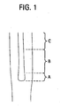
- Figure 1 illustrates a consolidated inner cane overclad with silica (core blank) that includes an alkali doped inner core 10 and a silica outer core 12. This figure illustrates puddling of the inner core 10 during consolidation. More specifically, it illustrates the inner core 10 has been distorted, and that it has a bulge (region A).
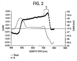
- FIG. 2 is a graph of measured a variation of the distorted inner core blank diameter (diameter vs. axial distance), after consolidation. This figure illustrates that the inner core diameter has increased from about 48.75 mm to about 49.75 mm, and that much of diameter increase occurred (49.25 mm to 49.75 mm) in relatively small region A of the inner core 10.
- US-A-4362542 discloses a method of manufacturing optical fiber care comprising steps satisfying steps (i) and (ii) of claim 1. Attention is also directed is also directed to WO2005/021455 .
- a method of manufacturing optical fiber cane comprises the steps of: (i) providing a core rod manufactured of relatively low viscosity glass; (ii) depositing Si based soot around the inner core rod to form a soot preform, the soot being of relatively high viscosity material such that the softening point of the low viscosity glass is at least 200°C lower than the softening point of the high viscosity outer core region; and (iii) consolidating the soot of the soot perform by exposure to hot zone at temperatures of 1000°C- 1600°C.
- the soot is consolidated by satisfying at least one of conditions (a) and (b) set out in claim 1 below
- a method of manufacturing optical fiber cane comprises the steps of: (i) providing an inner core rod manufactured of relatively low viscosity glass such that its softening paint; T s1 (temperature at which viscosity is 10 6.6 Pas (10 7.6 poise)) is less than or equal to 1470°C; (ii) depositing SiO 2 based soot around the inner core rod to form a soot preform, the soot made of relatively high viscosity material such that its softening point, T s2 (temperature at which viscosity is 10 6.6 Pas(10 7.6 poise)) greater than or equal to 1600°C where the softening point of the low viscosity glass is at least 200°C lower than the viscosity of the high viscosity outer core region and (iii) consolidating the soot of the soot perform by exposure to hot zone at temperatures of 1200°C-1600°C, by heating the outer portion of the soot perform at a relatively fast heating rate,
- the heating rate is at least 7°C /min, or it may be 12°C /min, 25°C /min, 50°C /min; 60°C /min; 75°C /min, 100C /min, or any value there between.
- These heating rates may be achieved, for example, by moving the perform at a relatively high speed through a non-isothermal hot zone (i) the heating elements relative to the soot perform, or the soot perform relative to the heating elements.
- This speed is at least 25 mm/min, and may be for example 30mm/min, 35 mm/min, 40 mm/min, 50 mm/min, 100 mm/min, 150 mm/min, 200 mm/mm, or any speed there between, or by increasing the heating element(s) temperature with time.
- One advantage of the present invention reduction or eliminate of "puddling", which advantageously increases the amount of usable cane after consolidation.
- Another advantage is reduction or elimination of uneven dopant redistribution, reduction in distortion and increase in the usable length of the blank, resulting in cost savings, as well as improved process control and better fiber attributes.
- Figure 1 is a photograph of a cane with distorted core
- Figure 2 is a graph of measured a variation of the distorted inner core diameter after consolidation.
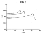
- Figure 3 is a plot of inner core radii corresponding to three inner core canes consolidated at a relatively low down-drive speed and to one inner core cane consolidated according to an embodiment of the present invention at a relatively high down-drive speed;
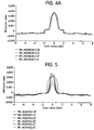
- Figure 4A illustrates refractive index profiles of the glass rods redrawn from different parts of the consolidated canes made according to the embodiments of present invention
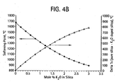
- Figure 4B is a graph of softening point (T, in degreee C), and ⁇ T s , vs. K 2 O concentration in silica glass;
- Figure 5 is shows the typical variation in refractive index profile amongst canes subjected to puddling
- Figure 6 summarizes the two sets of data, showing estimated potassium level of the inner cane regions (K concentration in the inner core rod versus axial position, after consolidation, for two differently sintered canes;
- Figure 7 shows a method of depositing glass soot
- Figure 8 depicts a method for doping a glass tube with an alkali metal oxide
- Figure 9 illustrates a process for drawing a glass rod according to one embodiment of the present invention.
- Figure 10 illustrates a partially cross-sectional side view of a soot perform in a consolidation furnace.
- a method of manufacturing optical fiber includes the steps of (i) providing a core rod 144 manufactured of relatively low viscosity glass '(for example a glass having a softening temperature T s1 at 10 6.6 Pas(10 7.6 poise) of less than or equal to 1470 °C) glass; (ii) depositing SiO 2 based soot 162 around the inner core rod 144 to form a soot perform 160, the soot made of relatively high viscosity material (for example, a material with softening point, T s2 , at 10 6.6 pa.s(10 7.6 poise of greater than or equal to 1600°C); and (iii) forming the fiber cane by consolidating the soot of by exposure to a hot zone at temperatures of 1200°C-1600°C, where the softening temperature of the low viscosity glass is at least 200°C lower than softening temperature of the glass in the high viscosity outer core region, the
- the ratio of inner core/outer core diameter is maintained within less than +/- 5% at least over 80 % of the inner core length in the consolidated blank (i.e., ((inner diameter/outer diameter)-average of (inner diameter/outer diameter))/(average of (inner diameter/outer diameter)) is less than +/- 0.05 over 80 %, and preferably over 98% of the inner core length in the consolidated blank.
- a low viscosity glass may be, for example, glass containing K 2 O, Na 2 O, LiO 2 , Rb 2 O, Cs 2 O, and mixtures thereof.
- the alkali metal oxide is preferably present in the cane in an average concentration in the core cane of at least 0.5 mole,% (% by mole, preferably between about 0.5 to 2.5 mole %, more preferably between about 0.5 to 2 mole %, more preferably between 0.5 and 1.5 mole %, more preferably between about 0.75 to 1.25 mole %.
- average concentration as used herein, we mean the average concentration over the entire core.
- the silica based core rod i.e., inner core rod
- the silica based core rod also comprises fluorine and chlorine.
- the silica based core rod also comprises fluorine and chlorine.
- the soot corresponding to the outer core region is consolidated by heating the soot perform at a relatively fast heating rate, the rate of heating being sufficient to densify the soot, so as to render the densified material with enough rigidity to confine the heated core rod so as to prevent puddling of the heated core rod.
- the ratio of the change of inner core diameter to outer core (blank) diameter is kept to less than 10%, and preferably to less than 5% along any 80 % the axial length of the consolidated perform, and/or (ii) the alkali concentration is constant (when measured at the same radius) along the length of the consolidated rod within plus or minus 10%, more preferably within 5% of the average alkali concentration.
- this heating rate is sufficient to densify the soot before the core rod softens sufficiently to puddle.
- the relatively fast heating rate is at least 6°C/min.
- this heating rate may be at least 7°C /min, or it may be 12°C /min, 25°C /min, 50°C /min; 60°C /min; 75°C /min, 100°C /min, or any heating rate therebetween.
- These heating rates may be achieved, for example, by moving the perform relative to a non-isothermal hot zone at a relatively high speed through a non-isothermal hot zone (my moving either the heating elements relative to the soot perform, or the soot perform relative to the heating elements).
- This speed is at least 25mm/min, and may be 30mm/min, 35 mm/min, 40 mm/min, 50 nim/min, 100 mm/min, 150 mm/min, 200 mm/min, or any speed there between, or by increasing the heating element(s) temperature with time.
- the heating rate(s) may be achieved by increasing the heating element(s) temperature with time.
- puddling can be minimized by minimizing the temperature on the core cane, for example by utilizing fast sinter rates of the outer core soot. In doing so, we provide enough heat/time for the blank to sinter, but minimize the time of exposure of the core cane to high axial and radial temperatures:
- Figure 3 is a plot of the inner core radii three core canes consolidated at a relatively low down-drive speed and one core cane consolidated according to an embodiment of the present invention at a relatively high down-drive speed.
- the core canes consolidated at a relatively low speed include puddling regions P.
- Figure 3 illustrates that puddling was minimized and/or eliminated when sintering was performed at a relatively high sintering rate.
- Figure 4A illustrates refractive index profiles of the glass rods redrawn from different parts of the consolidated canes made according to the present invention. This figure shows that there is very little variation in the four refractive index profiles.
- the four measurements correspond to four locations, spaced equidistantly, in progressive order from top to bottom of the cane.
- the reduction in puddling corresponds to down-drive speeds of 14 mm/min (heating rate of 7°C/min).
- the down-drive speed is at least 25 mm/min (heating rate of 12.5°C/min).
- the down drive speed may be at least 35 mm/min (heating rate of 17.5°C/min), or it may be 40 mm/min (heating rate of 20°C/min), 50 mm/min (heating rate of 25°C/min), 100 mm/min (heating rate of 50°C/min), 120 mm/min (heating rate of 60°C/min), 150 mm/min (heating rate of 75°C/min), 200 mm/min (heating rate of 100°C/min), or any speed there between.
- the softening point temperature is that temperature at which viscosity of the glass is 10 6.6 Pas( 10 7.6 poise)
- Table 2, bellow provides the softening points for several exemplary glasses, including softening temperatures of a pure silica glass, germania and fluorine doped silica glasses and the corresponding softening temperatures of exemplary alkali doped silica glasses.
- Table 2 illustrates that the addition of alkali results in softening temperatures that are significantly lower than that of pure SiO 2 glass. Therefore, based on our above hypotheses, this can result in the difficulties in obtaining uniform (sintered) overclad alkali doped inner core cane preform because the low viscosity inner core cane flows and deforms non uniformly with respect to the outer clad during the sintering of the soot preform. This puddling of the preform has been observed experimentally and may represent significant problem.
- Figure 5 shows the typical variation in refractive index profile amongst canes where the puddling phenomenon occurs.
- This figure illustrates a large variation in index profiles of the six glass rods redrawn from different parts of the consolidated canes.
- the six measurements correspond to four locations, spaced equidistantly, in progressive order from top to bottom of the cane.
- the soot performs corresponding to Figures 4A and 5 were identical, and the consolidation of the soot performs were performed under the same conditions except, during sintering, the down drive speed of the soot perform corresponding to Figure 5 was 7 mm/min (corresponding to a heating rate of 3.5°C/min). Consolidating the perform using slower down-drive speed allows the core rod to heat sufficiently to puddle, before the over clad became rigid enough to constrain the core rod from deforming.
- Figure 6 summarizes the two sets of data, showing estimated potassium level versus axial position within the blank.
- the faster rate process (Fast sinter, F) of the present invention results in an axial distribution of potassium which is fairly uniform throughout the blank, whereas the standard sinter (S) speed causes the potassium to concentrate in the lower portion when puddling occurs.
- the fiber performs canes/fiber with alkali doped cores disclosed herein can be fabricated by the skilled artisan, for example, by providing an alkali doped glass rod and depositing on it silica soot (doped or undoped) by using standard OVD, MCVD, PCVD or VAD methods.
- silica soot doped or undoped
- the core region delta required for the optical fiber requires a ways of incorporating sufficient an alkali (R) such as potassium (K), sodium (Na), rubidium.
- Rb lithium (Li) or cesium (Cs), in the core, and are calculated as the corresponding alkali oxide (R 2 O as: K 2 O, Na 2 O Rb 2 O Cs 2 O, Li 2 O preferably in 0.5-2.5 mole %, more preferably in 0.5-1.5 mole % range.
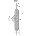
- FIG. 7 is an illustration of a conventional outside vapor deposition process
- at least one soot burner 156 is used to deposit multiple layers of silica soot 162 onto a mandrel 144 to form soot preform 160 .
- the resultant soot preform is then dried using standard chlorine drying techniques.
- the soot is then doped with fluorine by exposing the soot to an atmosphere of a fluorine containing compound (e.g., SiF 4 ) for a time and at a temperature sufficient to result in removal of much or all of the chlorine remaining from the drying step.
- a fluorine containing compound e.g., SiF 4
- the exposure to a fluorine-containing atmosphere is done at temperatures preferably less than about 1100°C to avoid doping the glass with high levels of fluorine.
- Low levels of fluorine doping are desirable, i.e., 0.1 to 0.4 wt. % fluorine, for example.
- the resultant fluorine (and potentially chlorine) doped soot tube is then consolidated.
- the resultant glass tube 106 is preferably first mounted between chucks in a lathe 101 (such as a glass-working lathe or a conventional modified chemical vapor deposition (MCVD) glass-forming lathe).
- a lathe 101 such as a glass-working lathe or a conventional modified chemical vapor deposition (MCVD) glass-forming lathe.
- a preferably annular reservoir 108 for receiving an alkali metal source compound 110 is formed near one end of tube 106 by forging two annular neck-like deformations 112 in the wall of tube 106 by flame working or otherwise welding the reservoir to the tube.
- the annular neck-like deformations 112 are about 2 cm from each other.
- tube 106 Preferably, to prevent crystallization of the alkali metal, it is desirable that tube 106 , and any additional glass deposited on the inside of tube 106 , be essentially chlorine free.
- essentially chlorine free we mean exhibiting a chlorine content sufficiently low that optical losses due to alkali chloride crystallization are avoided.
- a chlorine content preferably less than about 500 ppm by weight is desired for this purpose; more preferably less than about 100 ppm by wt.; and most preferably less than about 50 ppm by wt.
- silica glass tube 106 , and any additional glass deposited therein should be essentially free of "water”.
- water we mean the hydroxyl group OH.
- Glass tube 106 contains less than about 100 ppb by wt. OH; and more preferably less than about 20 ppb by wt.
- conventional chlorine drying techniques may be employed during manufacture of the silica glass tube.
- alkali source compound 110 is introduced into tube 106 at reservoir 108 and heated by heat source 114 to form a vapor as tube 106 is rotated.
- Oxygen or a carrier gas is flowed into the inlet 116 of tube 106 through rotating seal 118 , and portion 120 of tube 106 downstream of the alkali metal oxide source compound 110 is heated to facilitate diffusion of the alkali metal oxide into interior surface 122 of tube 106 .
- the tube 106 does not have any preform components inserted therein, such as another glass rod or the like.
- the portion 120 of tube 106 downstream of the alkali metal oxide source compound 110 should be heated to a temperature sufficient to promote rapid diffusion of the alkali into surface 122 and to prevent devitrification of the glass.
- portion 120 of tube 106 downstream of alkali metal oxide source compound 110 is heated by heat source 124 to above 1500°C ; more preferably between about 1500°C and 2000°C.
- heat source 124 is traversed along the length of portion 120 of tube 106 .
- Alkali metal oxide source compound 112 preferably comprises an element selected from the group consisting of K, Na, Li, Cs, and Rb.
- alkali metal oxide source compound 110 is a bromide, iodide or fluoride.
- the alkali metal oxide source compound 110 is KBr, KI or KNO 3 .
- the alkali metal oxide e.g., K 2 O, Na 2 O, LiO 2 , Rb 2 O Cs 2 O and mixtures thereof
- the alkali metal oxide is preferably diffused throughout a depth of between about 100 microns and 500 microns from the inside diffusion surface 122 of tube 106 prior to collapse of tube 106 thereby forming an alkali oxide doped glass tube.
- the diffused alkali metal oxide dopant concentration (in wt. %) in the tube varies radially.
- the glass article e.g.
- tube 106 is doped such that the concentration is highest on an inner half portion 107 and lower in an outer half portion 109 , as shown in the enlarged view of Figure 8 .
- the demarcation point between the inner and outer half portions is defined by and located at half the radial thickness (illustrated by dotted line 111 ) of the tube 106 .
- the diffusion is preferably such that the peak concentration of alkali dopant in the outer half portion 109 is less than 50% of the peak concentration (in wt. %) of the inner half portion 107 .
- the diffusion process may be followed by the step of further heating tube 106 to promote a partial collapse of tube 106 by conventional methods as are known in the art (or by the dry methods described herein) to both reduce the inside surface area through which the alkali metal oxide might be lost and to thicken the layer of glass into which the alkali metal oxide has been diffused.
- the diffusion surface of the tube 122 may optionally be etched with an etchant, suitable for removing silica glass, to a depth sufficient to remove unwanted impurities that may have diffused through the diffusion surface 122 of the tube.
- An aqueous HF solution may be used as an etchant, for example.
- a fluoride gas such as, for example, CF 4 , SF 6 , NF 3 , C 2 F 6 or a mixture thereof, is employed.
- the amount of material removed from inner surface 122 is dependent upon processing conditions during diffusion and any partial tube collapse, but the etching conditions are preferably sufficient to result in the removal of glass from surface 122 to a depth of at least about 5 percent of the total diffusion depth of the alkali metal oxide.
- silica glass tube 106 is further heated with a heat source 124 to collapse tube 106 downstream of alkali metal oxide source compound 110 and form an alkali metal oxide-doped solid glass rod 132 .
- Collapse of tube 106 is accomplished according to conventional methods known in the art, such as heating with a suitable heat source (e.g., a torch).
- a suitable heat source e.g., a torch
- the solid alkali-doped glass rod 132 is then cut from that portion of glass containing alkali metal source compound reservoir 108 .
- the solid alkali metal oxide-doped glass rod 132 is etched with a suitable etchant to remove some or all hydrated glass which may have been formed by the torch during collapse of the tube 106 .
- a dry heat source is used for collapse, for example, an induction or resistance heater, a plasma torch, or a dry heat source which uses a non-hydrogen containing fuel, such as CO, then etching may not be needed.
- Utilizing a dry heat source for the doping and/or collapsing steps is believed to minimize re-wetting of the outside of the tube, i.e., diffusing OH (water) into the tube from the outside and may, therefore, further reduce fiber attenuation.
- a dry heat source is one which does not induce any appreciable OH (water) into the tube.
- the alkali-doped rod 132 when collapsed preferably comprises (similar to the tube 106 ) concentrations of alkali metal oxide that vary radially and which are such that the portion corresponding to the inner half portion 107 has the highest peak concentration (in wt. %) of alkali dopant and the portion corresponding to the outer half portion 109 has a lower peak concentration.
- the peak concentration of alkali dopant is at the center of the rod and the concentration at half the radius is less than 50% of the peak concentration; and more preferably less than 25%.
- Doped glass rod 132 may be heated in a redraw furnace 136 and drawn into a smaller diameter glass rod 144 . This redraw process is illustrated in Figure 9 .
- a glass handle 130 is attached to the alkali-doped glass rod 132 resulting from the collapse stage described supra and the alkali-doped glass rod 132 is mounted in a moving downfeed support 134 above a conventional redraw furnace 136 .
- a sacrificial glass rod 138 which may be attached to the bottom of alkali-doped glass rod 132 , is pulled by motor-driven tractors 140 , thereby causing the alkali-doped glass rod 132 to be drawn at a suitable rate.
- the outer diameter dimension ( d1 ) of the small diameter glass rod 144 resulting from the drawing process is preferably in the range of 3 mm to 10 mm; more preferably less than 6 mm in diameter dimension. If the diameter dimension of rod 132 resulting from the collapse step is within the desired range, rod 132 resulting from collapse step 126 may be used as glass rod 144 .
- the small diameter glass rod 144 should have a peak concentration of K 2 O of more than 0.5 wt%, preferably between about 1 wt. % and 5 wt. %. In particular, having a very small diameter of the alkali-doped rod is advantageous because this concentrates the transition metal impurities present in the rod very near the fiber's centerline where their negative impact is minimized.
- small diameter glass rod 144 is further overclad.
- the small diameter alkali-doped_glass inner core rod 144 may be used as a starting rod upon which additional porous glass soot 162 is deposited as overclad (i.e., outer core) using an OVD method, as is known in the art, to form an assembly 160 .
- a typical outside vapor deposition method is illustrated in Figure 7 .
- a glass handle 154 is attached to small diameter alkali-doped glass rod 144 (corresponding to the inner core) manufactured, for example as heretofore described, and becomes an integral part of the resulting preform.
- Handle 154 provides a method of supporting the silica glass preform resulting from the deposition process during later processing steps.
- the glass rod 144 (inner core rod) having the attached handle 154 is mounted in a lathe where it is rotated and translated with respect to burner 156 which may be, for example, of the type disclosed in U.S. Pat. 4,165,223 .
- Fuel gas and oxygen, or air, are supplied to burner 156 from a source (not shown). This mixture is burned to produce a flame which is emitted from burner 156 .
- a silica precursor gas-vapor mixture is oxidized within the flame to form a silica-containing soot stream 158 which is directed toward glass rod 144 .
- Suitable means for delivering the gas-vapor mixture to burner 156 are well known in the art; for an illustration of such means reference is made to U.S. Pat. Nos.
- Composite soot preform 160 is formed by traversing glass rod 144 many times with respect to burner 156 to cause a build-up of many layers of silica soot-containing to form soot coating 162 .
- the translating motion could also be achieved by moving burner 156 back and forth along rotating glass rod 144 or by the combined translational motion of both burner 156 and glass rod 144 .
- Soot coating 162 forms at least a portion of the core glass of the composite preform 160 which is preferably comprised of substantially pure silica.
- the soot coating has a density greater than 0.35 g/cc, more preferably between about 0.35 g/cc and 0.5 g/cc.
- the composite preform 160 is then dried by exposing it to a chlorine-containing gas while being heated in a furnace to a temperature of about 1000°C.
- the preform 160 is then optionally fluorine doped.
- the preform 160 is preferably fluorine doped by exposing the preform to a fluorine-containing gas at temperatures (e.g. about 1000°C) suitable for causing the soot to become doped with the fluorine. In this way, the outer core region is formed.
- the fluorine doping step is only carried out long enough to allow a relatively small amount of fluorine (0.1 wt % to 0.4 wt %), for example.
- the preform is then consolidated by heating the preform 160 to a suitable temperature for consolidating the preform.
- a soot laden perform 160 is situated in a consolidation furnace and is gradient sintered in a hot zone having temperatures between 1000 °C and 1600 °C, more preferably between 1200 °C and 1600°C, most preferably between 1400 °C or 1450 °C and 1600 °C.
- the heating rate and/or down drive speed is sufficient to permit soot consolidation, so as to (i) render the densified material with enough rigidity to confine the heated inner core rod so as to prevent it from puddling, and/or (ii) before the inner core rod heats up so as to soften sufficiently to puddle, and/or (iii) densify the soot to form a glass clad while maintaining the ratio of inner core/outer core diameter within 10%.
- the relatively fast heating rate is at least 6°C/min.
- the this speed may be at least 7°C /min, or it may be 12°C /min, 25°C /min, 50°C /min; 60°C /min; 75°C /min, 100°C /min, or any speed there between.
- the change of inner core diameter to outer blank diameter becomes less than 10% along at least 75 %, and preferably over 95%, of the axial length of the consolidated perform (cane).
- Most preferably at least 98% of the consolidated perform exhibits less than 10% change of inner core diameter to outer blank diameter.
- the down-drive speed is at least 25 mm/min.
- the down drive speed may be at least 35 mm/min, or it may be 40 mm/min, 50 mm/min, 100 mm/min; 125 mm/min, 150 mm/min, 200 mm/min, or any speed there between.
- Composite preform 160 is heated in consolidation furnace 178 , shown in Fig . 10 , to form consolidated optical fiber perform 164 .
- Consolidation furnace 178 comprises a high silica content muffle 180 surrounded by heating elements 182 .
- a high silica content liner 184 typically separates heating elements 182 from muffle 180 .
- the term "high silica content” as used herein means pure fused silica or a high silica content glass such as a borosilicate glass.
- Consolidation gases 186 are fed to the bottom of muffle 184 through a conical section 188 which is affixed thereto. Conical section 188 is supported by rings and 192 . The consolidation gases 186 flow through one or more holes in conical section 188 .
- the consolidation atmosphere may contain helium (about 1 standard liter/min), oxygen, and an chlorine (40 to 50 standard cm/ min) to aid in water removal from the preform.
- chlorine permeates the interstices of the soot preform and flushes out any OH, H 2 or H 2 O contained therein.
- Soot contains core preform 160 is then heated at a high temperature (generally in the range of between about 1450° C to about 1600° C, depending upon preform composition) until the deposited soot consolidates and transforms into a solid, high-purity glass having superior optical properties.
- a high temperature generally in the range of between about 1450° C to about 1600° C, depending upon preform composition
- the resultant clear glass core cane may then be redrawn to form a second core rod, i.e. a glass rod which contains at least a portion of the core of an optical fiber drawn therefrom.
- the second core rod may then further processed by adding additional glass, either by sleeving with a glass tube (either a glass tube or soot tube), through depositing glass soot by chemical vapor deposition for example, by both sleeving and chemical deposition, or through other methods as are known in the art, to form a complete optical fiber preform ready to be drawn into an optical fiber.
- the additional glass may comprise core glass, cladding glass or both core and cladding glass.
- the additional glass may take one or more several additional deposition steps to achieve the desired thickness, wherein after each step, the soot is dried, doped, consolidated and redrawn into a smaller diameter rod. After the final consolidation step the cane may be drawn into optical fiber.
Landscapes
- Chemical & Material Sciences (AREA)
- Engineering & Computer Science (AREA)
- Geochemistry & Mineralogy (AREA)
- Organic Chemistry (AREA)
- Materials Engineering (AREA)
- Manufacturing & Machinery (AREA)
- Life Sciences & Earth Sciences (AREA)
- General Life Sciences & Earth Sciences (AREA)
- General Chemical & Material Sciences (AREA)
- Chemical Kinetics & Catalysis (AREA)
- Physics & Mathematics (AREA)
- Thermal Sciences (AREA)
- Glass Compositions (AREA)
- Manufacture, Treatment Of Glass Fibers (AREA)
- Yarns And Mechanical Finishing Of Yarns Or Ropes (AREA)
- Materials For Medical Uses (AREA)
Claims (9)
- Procédé de fabrication de canne de fibre optique comprenant les étapes consistant à :(i) fournir une tige de coeur réalisée en verre de viscosité relativement basse ;(ii) déposer de la suie à base de Si autour de la tige de coeur pour former une préforme de suie, ladite suie étant réalisée en matériau à viscosité relativement élevée, de sorte que le point de ramollissement de la zone de coeur intérieure à basse viscosité soit inférieur d'au moins 200°C au point de ramollissement de la zone de coeur extérieure à viscosité plus élevée;(iii) consolider ladite suie de ladite préforme de suie par exposition à une zone chaude à des températures de 1200°C-1600°C, en satisfaisant au moins l'une des conditions suivantes : (a) déplacement de ladite préforme de suie par rapport à ladite zone chaude à une vitesse d'au moins 25 mm/min, ladite vitesse étant suffisante pour densifier ladite suie, de manière à conférer au matériau densifié une rigidité suffisante pour confiner la tige de coeur chauffée afin de prévenir son puddlage ; ou (b) chauffage de la partie extérieure de ladite préforme de suie à une vitesse de chauffage d'au moins 6°C/min, ladite vitesse de chauffage étant suffisante pour densifier ladite suie avant que la tige de coeur se ramollise suffisamment pour puddler.
- Procédé de fabrication de canne de fibre optique selon la revendication 1, dans lequel ladite vitesse de chauffage est d'au moins 25°C/min.
- Procédé de fabrication de canne de fibre optique selon la revendication 1, dans lequel ladite vitesse de chauffage est d'au moins 50°C/min.
- Procédé de fabrication de canne de fibre optique selon la revendication 1 :dans lequel ladite tige de coeur correspond à un coeur intérieur et ladite suie consolidée correspond à un coeur extérieur, formant la canne de fibre en consolidant ladite suie par ladite exposition à ladite zone chaude en déplaçant ladite préforme de suie par rapport à ladite zone chaude à ladite vitesse de chauffage pour densifier ladite suie pour former une gaine de verre et maintenir le rapport de changement de diamètre du coeur intérieur au coeur extérieur à 10% maximum.
- Procédé de fabrication de canne de fibre optique selon la revendication 1, dans lequel ladite tige de coeur est constituée de silice dopée au sodium ou au potassium.
- Procédé de fabrication de canne de fibre optique selon la revendication 5, dans lequel ladite tige de coeur comprend 0,5 à 5% en poids de potassium.
- Procédé de fabrication de canne de fibre optique selon la revendication 1, dans lequel :(i) le verre à viscosité relativement basse a un point de ramollissement, Ts1, à 107,6 poises égal ou inférieur à 1470°C, ledit verre comprenant au moins 0,5 mole % de dopant à l'alcali ;(ii) ladite suie à base de Si réalisée en matériau à viscosité relativement élevée a un point de ramollissement Ts2 à 107,6 poises égal ou supérieur à 1600°C ; et(iii) la consolidation de ladite suie de ladite préforme de suie est effectuée en satisfaisant la condition (b).
- Procédé de fabrication de canne de fibre optique selon la revendication 1, dans lequel ledit mouvement de la préforme de suie par rapport à la zone de chauffage est d'au moins 35 mm/min.
- Procédé de fabrication de canne de fibre optique selon la revendication 8, dans lequel ledit mouvement de la préforme de suie par rapport à la zone de chauffage est d'au moins 50 mm/min.
Applications Claiming Priority (2)
| Application Number | Priority Date | Filing Date | Title |
|---|---|---|---|
| US90399507P | 2007-02-28 | 2007-02-28 | |
| PCT/US2008/002306 WO2008106046A1 (fr) | 2007-02-28 | 2008-02-21 | Réduction de déformation de préforme tige/fibre optique par consolidation |
Publications (2)
| Publication Number | Publication Date |
|---|---|
| EP2125645A1 EP2125645A1 (fr) | 2009-12-02 |
| EP2125645B1 true EP2125645B1 (fr) | 2011-04-20 |
Family
ID=39523837
Family Applications (1)
| Application Number | Title | Priority Date | Filing Date |
|---|---|---|---|
| EP08725896A Active EP2125645B1 (fr) | 2007-02-28 | 2008-02-21 | Réduction de déformation de préforme tige/fibre optique par consolidation |
Country Status (9)
| Country | Link |
|---|---|
| US (1) | US8011208B2 (fr) |
| EP (1) | EP2125645B1 (fr) |
| JP (1) | JP5249954B2 (fr) |
| KR (1) | KR20090127300A (fr) |
| CN (1) | CN101657389B (fr) |
| AT (1) | ATE506328T1 (fr) |
| DE (1) | DE602008006371D1 (fr) |
| DK (1) | DK2125645T3 (fr) |
| WO (1) | WO2008106046A1 (fr) |
Families Citing this family (11)
| Publication number | Priority date | Publication date | Assignee | Title |
|---|---|---|---|---|
| KR101066281B1 (ko) * | 2003-08-29 | 2011-09-20 | 코닝 인코포레이티드 | 알칼리 금속 산화물을 함유하는 광섬유, 및 그 제조 방법및 장치 |
| US8869566B2 (en) * | 2010-08-27 | 2014-10-28 | Corning Incorporated | Soot radial pressing for optical fiber overcladding |
| JP5817462B2 (ja) | 2011-01-27 | 2015-11-18 | 住友電気工業株式会社 | 光ファイバ母材製造方法 |
| JP5974455B2 (ja) | 2011-11-21 | 2016-08-23 | 住友電気工業株式会社 | 光ファイバ母材、光ファイバ製造方法および光ファイバ |
| JP5625037B2 (ja) * | 2012-03-23 | 2014-11-12 | 株式会社フジクラ | ガラス母材の製造方法 |
| JP6010587B2 (ja) * | 2014-07-11 | 2016-10-19 | 株式会社フジクラ | マルチコアファイバ用母材の製造方法、及び、これを用いたマルチコアファイバの製造方法 |
| US9919955B2 (en) * | 2015-07-24 | 2018-03-20 | Ofs Fitel, Llc | Optical fiber with low loss and nanoscale structurally homogeneous core |
| JP6795983B2 (ja) * | 2016-09-12 | 2020-12-02 | 株式会社フジクラ | 光ファイバ用母材の製造方法、及び、これを用いた光ファイバの製造方法 |
| NL2020974B1 (en) * | 2018-05-23 | 2019-12-02 | Draka Comteq Bv | A device, system and method for forming a core rod for optical fibers |
| US11655183B2 (en) * | 2020-06-11 | 2023-05-23 | Lawrence Livermore National Security, Llc | System and method for optical fiber preform preparation via high-surface-area coating |
| US20230202904A1 (en) * | 2020-07-03 | 2023-06-29 | Sumitomo Electric Industries, Ltd. | Method for producing optical fiber base material, and optical fiber base material |
Family Cites Families (16)
| Publication number | Priority date | Publication date | Assignee | Title |
|---|---|---|---|---|
| US3826560A (en) | 1972-03-30 | 1974-07-30 | Corning Glass Works | Method of forming a light focusing fiber waveguide |
| DE2546162B1 (de) * | 1975-10-15 | 1976-09-23 | Jenaer Glaswerk Schott & Gen | Lichtleitfaser mit Brechungsindexgradient zur Nachrichtenuebertragung |
| US4362542A (en) * | 1976-12-30 | 1982-12-07 | Pedro B. Macedo | Method of producing a strong optical fiber |
| US4165223A (en) | 1978-03-06 | 1979-08-21 | Corning Glass Works | Method of making dry optical waveguides |
| US4173305A (en) | 1978-03-10 | 1979-11-06 | Corning Glass Works | System for delivering materials to deposition site on optical waveguide blank |
| JPS599491B2 (ja) * | 1979-07-20 | 1984-03-02 | 日本電信電話株式会社 | 光フアイバ用母材の製造方法 |
| JPS61117127A (ja) * | 1984-10-13 | 1986-06-04 | Furukawa Electric Co Ltd:The | 光フアイバ用多孔質ガラス母材の処理方法 |
| JPS63236727A (ja) * | 1987-03-25 | 1988-10-03 | Tatsuta Electric Wire & Cable Co Ltd | 光フアイバ母材の製造方法 |
| JPH01219034A (ja) * | 1988-02-26 | 1989-09-01 | Sumitomo Electric Ind Ltd | 光フアイバ用ガラス母材の製造方法 |
| JPH04325433A (ja) * | 1991-04-26 | 1992-11-13 | Furukawa Electric Co Ltd:The | 光ファイバ用母材の製造方法 |
| US5356449A (en) * | 1993-05-24 | 1994-10-18 | At&T Bell Laboratories | Vad process improvements |
| US5656057A (en) * | 1995-05-19 | 1997-08-12 | Corning Incorporated | Method for drying and sintering an optical fiber preform |
| US5740297A (en) * | 1995-08-31 | 1998-04-14 | Sumitomo Electric Industries, Ltd. | Dispersion-compensating fiber and method of fabricating the same |
| CN100345782C (zh) * | 2001-06-28 | 2007-10-31 | 古河电气工业株式会社 | 光纤预制体的制造方法以及烧结装置 |
| KR101066281B1 (ko) * | 2003-08-29 | 2011-09-20 | 코닝 인코포레이티드 | 알칼리 금속 산화물을 함유하는 광섬유, 및 그 제조 방법및 장치 |
| JP4870573B2 (ja) * | 2003-12-12 | 2012-02-08 | コーニング インコーポレイテッド | アルカリがドープされた光ファイバ、そのプリフォームおよびその作成方法 |
-
2008
- 2008-02-21 JP JP2009551683A patent/JP5249954B2/ja active Active
- 2008-02-21 DE DE602008006371T patent/DE602008006371D1/de active Active
- 2008-02-21 CN CN2008800119526A patent/CN101657389B/zh active Active
- 2008-02-21 DK DK08725896.8T patent/DK2125645T3/da active
- 2008-02-21 EP EP08725896A patent/EP2125645B1/fr active Active
- 2008-02-21 WO PCT/US2008/002306 patent/WO2008106046A1/fr active Application Filing
- 2008-02-21 AT AT08725896T patent/ATE506328T1/de not_active IP Right Cessation
- 2008-02-21 KR KR1020097020258A patent/KR20090127300A/ko not_active Application Discontinuation
- 2008-02-22 US US12/072,013 patent/US8011208B2/en active Active
Also Published As
| Publication number | Publication date |
|---|---|
| ATE506328T1 (de) | 2011-05-15 |
| US20080271495A1 (en) | 2008-11-06 |
| US8011208B2 (en) | 2011-09-06 |
| CN101657389B (zh) | 2012-09-26 |
| JP2010520140A (ja) | 2010-06-10 |
| EP2125645A1 (fr) | 2009-12-02 |
| JP5249954B2 (ja) | 2013-07-31 |
| DK2125645T3 (da) | 2011-07-18 |
| CN101657389A (zh) | 2010-02-24 |
| KR20090127300A (ko) | 2009-12-10 |
| DE602008006371D1 (de) | 2011-06-01 |
| WO2008106046A1 (fr) | 2008-09-04 |
Similar Documents
| Publication | Publication Date | Title |
|---|---|---|
| EP2125645B1 (fr) | Réduction de déformation de préforme tige/fibre optique par consolidation | |
| US7524780B2 (en) | Low loss optical fiber and method for making same | |
| EP2035869B1 (fr) | Fibre optique contenant un oxyde de métal alcalin | |
| EP1663890B1 (fr) | Fibre optique contenant un oxyde de metal alcalin et procedes et appareil pour sa fabrication | |
| US5917109A (en) | Method of making optical fiber having depressed index core region | |
| NO161730B (no) | Fremgangsmaate for fremstilling av en gjenstand av glass, hvorav i det minste en del er dopet med fluor. | |
| EP0915064B1 (fr) | Procédé de fabrication de préformes pour des guides optiques à coeur segmenté | |
| EP3359498B1 (fr) | Procédé de fabrication d'une préforme à coeur de verre pour fibres optiques | |
| US20050000250A1 (en) | Method for producing a tube consisting of quartz glass, tubular semi-finished product consisting of porous quartz glass, and the use of the same | |
| KR20060132674A (ko) | 광섬유 프리폼의 제조 방법 | |
| US20110244154A1 (en) | Method and cylindrical semi-finished product for producing an optical component | |
| US7155098B2 (en) | Method of manufacturing optical fiber preform using modified chemical vapor deposition including dehydration and dechlorination process and optical fiber manufactured by the method | |
| US7021083B2 (en) | Manufacture of high purity glass tubes | |
| US6928841B2 (en) | Optical fiber preform manufacture using improved VAD | |
| US7391946B2 (en) | Low attenuation optical fiber and its producing method in MCVD | |
| JPH0742131B2 (ja) | 光フアイバ用ガラス母材の製造方法 | |
| AU735014B2 (en) | Method of making optical fiber having depressed index core region | |
| JP2003238181A (ja) | 光ファイバ及び光ファイバの製造方法 |
Legal Events
| Date | Code | Title | Description |
|---|---|---|---|
| PUAI | Public reference made under article 153(3) epc to a published international application that has entered the european phase |
Free format text: ORIGINAL CODE: 0009012 |
|
| 17P | Request for examination filed |
Effective date: 20090917 |
|
| AK | Designated contracting states |
Kind code of ref document: A1 Designated state(s): AT BE BG CH CY CZ DE DK EE ES FI FR GB GR HR HU IE IS IT LI LT LU LV MC MT NL NO PL PT RO SE SI SK TR |
|
| RIN1 | Information on inventor provided before grant (corrected) |
Inventor name: RANEY, SONYA M Inventor name: BALAKRISHNAN, JITENDRA Inventor name: ONUH, CHUKWUEMEKA B Inventor name: TANDON, PUSHKAR Inventor name: KHANNA, SAMIR |
|
| 17Q | First examination report despatched |
Effective date: 20100309 |
|
| RIN1 | Information on inventor provided before grant (corrected) |
Inventor name: TANDON, PUSHKAR Inventor name: RANEY, SONYA M Inventor name: ONUH, CHUKWUEMEKA B Inventor name: KHANNA, SAMIR Inventor name: BALAKRISHNAN, JITENDRA |
|
| DAX | Request for extension of the european patent (deleted) | ||
| GRAP | Despatch of communication of intention to grant a patent |
Free format text: ORIGINAL CODE: EPIDOSNIGR1 |
|
| GRAS | Grant fee paid |
Free format text: ORIGINAL CODE: EPIDOSNIGR3 |
|
| GRAA | (expected) grant |
Free format text: ORIGINAL CODE: 0009210 |
|
| AK | Designated contracting states |
Kind code of ref document: B1 Designated state(s): AT BE BG CH CY CZ DE DK EE ES FI FR GB GR HR HU IE IS IT LI LT LU LV MC MT NL NO PL PT RO SE SI SK TR |
|
| REG | Reference to a national code |
Ref country code: GB Ref legal event code: FG4D |
|
| REG | Reference to a national code |
Ref country code: CH Ref legal event code: EP |
|
| REG | Reference to a national code |
Ref country code: IE Ref legal event code: FG4D |
|
| REF | Corresponds to: |
Ref document number: 602008006371 Country of ref document: DE Date of ref document: 20110601 Kind code of ref document: P |
|
| REG | Reference to a national code |
Ref country code: DE Ref legal event code: R096 Ref document number: 602008006371 Country of ref document: DE Effective date: 20110601 |
|
| REG | Reference to a national code |
Ref country code: DK Ref legal event code: T3 |
|
| REG | Reference to a national code |
Ref country code: NL Ref legal event code: T3 |
|
| LTIE | Lt: invalidation of european patent or patent extension |
Effective date: 20110420 |
|
| PG25 | Lapsed in a contracting state [announced via postgrant information from national office to epo] |
Ref country code: PT Free format text: LAPSE BECAUSE OF FAILURE TO SUBMIT A TRANSLATION OF THE DESCRIPTION OR TO PAY THE FEE WITHIN THE PRESCRIBED TIME-LIMIT Effective date: 20110822 Ref country code: LT Free format text: LAPSE BECAUSE OF FAILURE TO SUBMIT A TRANSLATION OF THE DESCRIPTION OR TO PAY THE FEE WITHIN THE PRESCRIBED TIME-LIMIT Effective date: 20110420 Ref country code: NO Free format text: LAPSE BECAUSE OF FAILURE TO SUBMIT A TRANSLATION OF THE DESCRIPTION OR TO PAY THE FEE WITHIN THE PRESCRIBED TIME-LIMIT Effective date: 20110720 Ref country code: SE Free format text: LAPSE BECAUSE OF FAILURE TO SUBMIT A TRANSLATION OF THE DESCRIPTION OR TO PAY THE FEE WITHIN THE PRESCRIBED TIME-LIMIT Effective date: 20110420 Ref country code: HR Free format text: LAPSE BECAUSE OF FAILURE TO SUBMIT A TRANSLATION OF THE DESCRIPTION OR TO PAY THE FEE WITHIN THE PRESCRIBED TIME-LIMIT Effective date: 20110420 |
|
| PG25 | Lapsed in a contracting state [announced via postgrant information from national office to epo] |
Ref country code: GR Free format text: LAPSE BECAUSE OF FAILURE TO SUBMIT A TRANSLATION OF THE DESCRIPTION OR TO PAY THE FEE WITHIN THE PRESCRIBED TIME-LIMIT Effective date: 20110721 Ref country code: CY Free format text: LAPSE BECAUSE OF FAILURE TO SUBMIT A TRANSLATION OF THE DESCRIPTION OR TO PAY THE FEE WITHIN THE PRESCRIBED TIME-LIMIT Effective date: 20110420 Ref country code: LV Free format text: LAPSE BECAUSE OF FAILURE TO SUBMIT A TRANSLATION OF THE DESCRIPTION OR TO PAY THE FEE WITHIN THE PRESCRIBED TIME-LIMIT Effective date: 20110420 Ref country code: IS Free format text: LAPSE BECAUSE OF FAILURE TO SUBMIT A TRANSLATION OF THE DESCRIPTION OR TO PAY THE FEE WITHIN THE PRESCRIBED TIME-LIMIT Effective date: 20110820 Ref country code: BE Free format text: LAPSE BECAUSE OF FAILURE TO SUBMIT A TRANSLATION OF THE DESCRIPTION OR TO PAY THE FEE WITHIN THE PRESCRIBED TIME-LIMIT Effective date: 20110420 Ref country code: ES Free format text: LAPSE BECAUSE OF FAILURE TO SUBMIT A TRANSLATION OF THE DESCRIPTION OR TO PAY THE FEE WITHIN THE PRESCRIBED TIME-LIMIT Effective date: 20110731 Ref country code: SI Free format text: LAPSE BECAUSE OF FAILURE TO SUBMIT A TRANSLATION OF THE DESCRIPTION OR TO PAY THE FEE WITHIN THE PRESCRIBED TIME-LIMIT Effective date: 20110420 Ref country code: FI Free format text: LAPSE BECAUSE OF FAILURE TO SUBMIT A TRANSLATION OF THE DESCRIPTION OR TO PAY THE FEE WITHIN THE PRESCRIBED TIME-LIMIT Effective date: 20110420 Ref country code: AT Free format text: LAPSE BECAUSE OF FAILURE TO SUBMIT A TRANSLATION OF THE DESCRIPTION OR TO PAY THE FEE WITHIN THE PRESCRIBED TIME-LIMIT Effective date: 20110420 |
|
| PG25 | Lapsed in a contracting state [announced via postgrant information from national office to epo] |
Ref country code: CZ Free format text: LAPSE BECAUSE OF FAILURE TO SUBMIT A TRANSLATION OF THE DESCRIPTION OR TO PAY THE FEE WITHIN THE PRESCRIBED TIME-LIMIT Effective date: 20110420 Ref country code: EE Free format text: LAPSE BECAUSE OF FAILURE TO SUBMIT A TRANSLATION OF THE DESCRIPTION OR TO PAY THE FEE WITHIN THE PRESCRIBED TIME-LIMIT Effective date: 20110420 |
|
| PLBE | No opposition filed within time limit |
Free format text: ORIGINAL CODE: 0009261 |
|
| STAA | Information on the status of an ep patent application or granted ep patent |
Free format text: STATUS: NO OPPOSITION FILED WITHIN TIME LIMIT |
|
| PG25 | Lapsed in a contracting state [announced via postgrant information from national office to epo] |
Ref country code: PL Free format text: LAPSE BECAUSE OF FAILURE TO SUBMIT A TRANSLATION OF THE DESCRIPTION OR TO PAY THE FEE WITHIN THE PRESCRIBED TIME-LIMIT Effective date: 20110420 Ref country code: RO Free format text: LAPSE BECAUSE OF FAILURE TO SUBMIT A TRANSLATION OF THE DESCRIPTION OR TO PAY THE FEE WITHIN THE PRESCRIBED TIME-LIMIT Effective date: 20110420 Ref country code: SK Free format text: LAPSE BECAUSE OF FAILURE TO SUBMIT A TRANSLATION OF THE DESCRIPTION OR TO PAY THE FEE WITHIN THE PRESCRIBED TIME-LIMIT Effective date: 20110420 |
|
| 26N | No opposition filed |
Effective date: 20120123 |
|
| REG | Reference to a national code |
Ref country code: DE Ref legal event code: R097 Ref document number: 602008006371 Country of ref document: DE Effective date: 20120123 |
|
| PG25 | Lapsed in a contracting state [announced via postgrant information from national office to epo] |
Ref country code: MC Free format text: LAPSE BECAUSE OF NON-PAYMENT OF DUE FEES Effective date: 20120229 |
|
| REG | Reference to a national code |
Ref country code: CH Ref legal event code: PL |
|
| PG25 | Lapsed in a contracting state [announced via postgrant information from national office to epo] |
Ref country code: CH Free format text: LAPSE BECAUSE OF NON-PAYMENT OF DUE FEES Effective date: 20120229 Ref country code: LI Free format text: LAPSE BECAUSE OF NON-PAYMENT OF DUE FEES Effective date: 20120229 |
|
| REG | Reference to a national code |
Ref country code: IE Ref legal event code: MM4A |
|
| PG25 | Lapsed in a contracting state [announced via postgrant information from national office to epo] |
Ref country code: IE Free format text: LAPSE BECAUSE OF NON-PAYMENT OF DUE FEES Effective date: 20120221 |
|
| PG25 | Lapsed in a contracting state [announced via postgrant information from national office to epo] |
Ref country code: BG Free format text: LAPSE BECAUSE OF FAILURE TO SUBMIT A TRANSLATION OF THE DESCRIPTION OR TO PAY THE FEE WITHIN THE PRESCRIBED TIME-LIMIT Effective date: 20110720 |
|
| PG25 | Lapsed in a contracting state [announced via postgrant information from national office to epo] |
Ref country code: MT Free format text: LAPSE BECAUSE OF FAILURE TO SUBMIT A TRANSLATION OF THE DESCRIPTION OR TO PAY THE FEE WITHIN THE PRESCRIBED TIME-LIMIT Effective date: 20110420 |
|
| PG25 | Lapsed in a contracting state [announced via postgrant information from national office to epo] |
Ref country code: TR Free format text: LAPSE BECAUSE OF FAILURE TO SUBMIT A TRANSLATION OF THE DESCRIPTION OR TO PAY THE FEE WITHIN THE PRESCRIBED TIME-LIMIT Effective date: 20110420 |
|
| PG25 | Lapsed in a contracting state [announced via postgrant information from national office to epo] |
Ref country code: LU Free format text: LAPSE BECAUSE OF NON-PAYMENT OF DUE FEES Effective date: 20120221 |
|
| PG25 | Lapsed in a contracting state [announced via postgrant information from national office to epo] |
Ref country code: HU Free format text: LAPSE BECAUSE OF FAILURE TO SUBMIT A TRANSLATION OF THE DESCRIPTION OR TO PAY THE FEE WITHIN THE PRESCRIBED TIME-LIMIT Effective date: 20080221 |
|
| REG | Reference to a national code |
Ref country code: FR Ref legal event code: PLFP Year of fee payment: 9 |
|
| REG | Reference to a national code |
Ref country code: FR Ref legal event code: PLFP Year of fee payment: 10 |
|
| REG | Reference to a national code |
Ref country code: FR Ref legal event code: PLFP Year of fee payment: 11 |
|
| P01 | Opt-out of the competence of the unified patent court (upc) registered |
Effective date: 20230527 |
|
| PGFP | Annual fee paid to national office [announced via postgrant information from national office to epo] |
Ref country code: NL Payment date: 20240111 Year of fee payment: 17 |
|
| PGFP | Annual fee paid to national office [announced via postgrant information from national office to epo] |
Ref country code: DE Payment date: 20240109 Year of fee payment: 17 Ref country code: GB Payment date: 20240111 Year of fee payment: 17 |
|
| PGFP | Annual fee paid to national office [announced via postgrant information from national office to epo] |
Ref country code: IT Payment date: 20240213 Year of fee payment: 17 Ref country code: FR Payment date: 20240108 Year of fee payment: 17 Ref country code: DK Payment date: 20240130 Year of fee payment: 17 |