EP2124706B1 - Schlauchanordnung für ein endoskop - Google Patents
Schlauchanordnung für ein endoskop Download PDFInfo
- Publication number
- EP2124706B1 EP2124706B1 EP08715835.8A EP08715835A EP2124706B1 EP 2124706 B1 EP2124706 B1 EP 2124706B1 EP 08715835 A EP08715835 A EP 08715835A EP 2124706 B1 EP2124706 B1 EP 2124706B1
- Authority
- EP
- European Patent Office
- Prior art keywords
- endoscope
- hose
- disposable
- accordance
- hose arrangement
- Prior art date
- Legal status (The legal status is an assumption and is not a legal conclusion. Google has not performed a legal analysis and makes no representation as to the accuracy of the status listed.)
- Not-in-force
Links
- 0 CC(CC(C(CC(C)CCCCCCCCC(*)C*(*)(C(CCC(C)C1C(CCCCCC2)[C@@](CN)C(CCC3)C1CCCC1)CC2[Cn])N=O)C2C4C(C*)(C5)C(C6)C4C1C3C6N)C2C5N)[C@@](C)*=CC Chemical compound CC(CC(C(CC(C)CCCCCCCCC(*)C*(*)(C(CCC(C)C1C(CCCCCC2)[C@@](CN)C(CCC3)C1CCCC1)CC2[Cn])N=O)C2C4C(C*)(C5)C(C6)C4C1C3C6N)C2C5N)[C@@](C)*=CC 0.000 description 2
Images


Classifications
-
- A—HUMAN NECESSITIES
- A61—MEDICAL OR VETERINARY SCIENCE; HYGIENE
- A61B—DIAGNOSIS; SURGERY; IDENTIFICATION
- A61B1/00—Instruments for performing medical examinations of the interior of cavities or tubes of the body by visual or photographical inspection, e.g. endoscopes; Illuminating arrangements therefor
- A61B1/00112—Connection or coupling means
- A61B1/00119—Tubes or pipes in or with an endoscope
-
- A—HUMAN NECESSITIES
- A61—MEDICAL OR VETERINARY SCIENCE; HYGIENE
- A61B—DIAGNOSIS; SURGERY; IDENTIFICATION
- A61B1/00—Instruments for performing medical examinations of the interior of cavities or tubes of the body by visual or photographical inspection, e.g. endoscopes; Illuminating arrangements therefor
- A61B1/00112—Connection or coupling means
- A61B1/00121—Connectors, fasteners and adapters, e.g. on the endoscope handle
- A61B1/00128—Connectors, fasteners and adapters, e.g. on the endoscope handle mechanical, e.g. for tubes or pipes
-
- A—HUMAN NECESSITIES
- A61—MEDICAL OR VETERINARY SCIENCE; HYGIENE
- A61B—DIAGNOSIS; SURGERY; IDENTIFICATION
- A61B1/00—Instruments for performing medical examinations of the interior of cavities or tubes of the body by visual or photographical inspection, e.g. endoscopes; Illuminating arrangements therefor
- A61B1/00131—Accessories for endoscopes
- A61B1/00135—Oversleeves mounted on the endoscope prior to insertion
-
- A—HUMAN NECESSITIES
- A61—MEDICAL OR VETERINARY SCIENCE; HYGIENE
- A61B—DIAGNOSIS; SURGERY; IDENTIFICATION
- A61B1/00—Instruments for performing medical examinations of the interior of cavities or tubes of the body by visual or photographical inspection, e.g. endoscopes; Illuminating arrangements therefor
- A61B1/00131—Accessories for endoscopes
- A61B1/0014—Fastening element for attaching accessories to the outside of an endoscope, e.g. clips, clamps or bands
-
- A—HUMAN NECESSITIES
- A61—MEDICAL OR VETERINARY SCIENCE; HYGIENE
- A61B—DIAGNOSIS; SURGERY; IDENTIFICATION
- A61B1/00—Instruments for performing medical examinations of the interior of cavities or tubes of the body by visual or photographical inspection, e.g. endoscopes; Illuminating arrangements therefor
- A61B1/012—Instruments for performing medical examinations of the interior of cavities or tubes of the body by visual or photographical inspection, e.g. endoscopes; Illuminating arrangements therefor characterised by internal passages or accessories therefor
- A61B1/018—Instruments for performing medical examinations of the interior of cavities or tubes of the body by visual or photographical inspection, e.g. endoscopes; Illuminating arrangements therefor characterised by internal passages or accessories therefor for receiving instruments
-
- A—HUMAN NECESSITIES
- A61—MEDICAL OR VETERINARY SCIENCE; HYGIENE
- A61B—DIAGNOSIS; SURGERY; IDENTIFICATION
- A61B1/00—Instruments for performing medical examinations of the interior of cavities or tubes of the body by visual or photographical inspection, e.g. endoscopes; Illuminating arrangements therefor
- A61B1/12—Instruments for performing medical examinations of the interior of cavities or tubes of the body by visual or photographical inspection, e.g. endoscopes; Illuminating arrangements therefor with cooling or rinsing arrangements
- A61B1/126—Instruments for performing medical examinations of the interior of cavities or tubes of the body by visual or photographical inspection, e.g. endoscopes; Illuminating arrangements therefor with cooling or rinsing arrangements provided with means for cleaning in-use
-
- A—HUMAN NECESSITIES
- A61—MEDICAL OR VETERINARY SCIENCE; HYGIENE
- A61B—DIAGNOSIS; SURGERY; IDENTIFICATION
- A61B1/00—Instruments for performing medical examinations of the interior of cavities or tubes of the body by visual or photographical inspection, e.g. endoscopes; Illuminating arrangements therefor
- A61B1/12—Instruments for performing medical examinations of the interior of cavities or tubes of the body by visual or photographical inspection, e.g. endoscopes; Illuminating arrangements therefor with cooling or rinsing arrangements
- A61B1/127—Instruments for performing medical examinations of the interior of cavities or tubes of the body by visual or photographical inspection, e.g. endoscopes; Illuminating arrangements therefor with cooling or rinsing arrangements with means for preventing fogging
-
- A—HUMAN NECESSITIES
- A61—MEDICAL OR VETERINARY SCIENCE; HYGIENE
- A61B—DIAGNOSIS; SURGERY; IDENTIFICATION
- A61B1/00—Instruments for performing medical examinations of the interior of cavities or tubes of the body by visual or photographical inspection, e.g. endoscopes; Illuminating arrangements therefor
- A61B1/227—Instruments for performing medical examinations of the interior of cavities or tubes of the body by visual or photographical inspection, e.g. endoscopes; Illuminating arrangements therefor for ears, i.e. otoscopes
-
- A—HUMAN NECESSITIES
- A61—MEDICAL OR VETERINARY SCIENCE; HYGIENE
- A61B—DIAGNOSIS; SURGERY; IDENTIFICATION
- A61B1/00—Instruments for performing medical examinations of the interior of cavities or tubes of the body by visual or photographical inspection, e.g. endoscopes; Illuminating arrangements therefor
- A61B1/233—Instruments for performing medical examinations of the interior of cavities or tubes of the body by visual or photographical inspection, e.g. endoscopes; Illuminating arrangements therefor for the nose, i.e. nasoscopes, e.g. testing of patency of Eustachian tubes
-
- A—HUMAN NECESSITIES
- A61—MEDICAL OR VETERINARY SCIENCE; HYGIENE
- A61B—DIAGNOSIS; SURGERY; IDENTIFICATION
- A61B1/00—Instruments for performing medical examinations of the interior of cavities or tubes of the body by visual or photographical inspection, e.g. endoscopes; Illuminating arrangements therefor
- A61B1/267—Instruments for performing medical examinations of the interior of cavities or tubes of the body by visual or photographical inspection, e.g. endoscopes; Illuminating arrangements therefor for the respiratory tract, e.g. laryngoscopes, bronchoscopes
-
- A—HUMAN NECESSITIES
- A61—MEDICAL OR VETERINARY SCIENCE; HYGIENE
- A61M—DEVICES FOR INTRODUCING MEDIA INTO, OR ONTO, THE BODY; DEVICES FOR TRANSDUCING BODY MEDIA OR FOR TAKING MEDIA FROM THE BODY; DEVICES FOR PRODUCING OR ENDING SLEEP OR STUPOR
- A61M25/00—Catheters; Hollow probes
- A61M25/0021—Catheters; Hollow probes characterised by the form of the tubing
- A61M25/0023—Catheters; Hollow probes characterised by the form of the tubing by the form of the lumen, e.g. cross-section, variable diameter
-
- F—MECHANICAL ENGINEERING; LIGHTING; HEATING; WEAPONS; BLASTING
- F16—ENGINEERING ELEMENTS AND UNITS; GENERAL MEASURES FOR PRODUCING AND MAINTAINING EFFECTIVE FUNCTIONING OF MACHINES OR INSTALLATIONS; THERMAL INSULATION IN GENERAL
- F16L—PIPES; JOINTS OR FITTINGS FOR PIPES; SUPPORTS FOR PIPES, CABLES OR PROTECTIVE TUBING; MEANS FOR THERMAL INSULATION IN GENERAL
- F16L11/00—Hoses, i.e. flexible pipes
- F16L11/04—Hoses, i.e. flexible pipes made of rubber or flexible plastics
- F16L11/12—Hoses, i.e. flexible pipes made of rubber or flexible plastics with arrangements for particular purposes, e.g. specially profiled, with protecting layer, heated, electrically conducting
- F16L11/122—Hoses provided with integrated fixing means, e.g. hooks
-
- F—MECHANICAL ENGINEERING; LIGHTING; HEATING; WEAPONS; BLASTING
- F16—ENGINEERING ELEMENTS AND UNITS; GENERAL MEASURES FOR PRODUCING AND MAINTAINING EFFECTIVE FUNCTIONING OF MACHINES OR INSTALLATIONS; THERMAL INSULATION IN GENERAL
- F16L—PIPES; JOINTS OR FITTINGS FOR PIPES; SUPPORTS FOR PIPES, CABLES OR PROTECTIVE TUBING; MEANS FOR THERMAL INSULATION IN GENERAL
- F16L11/00—Hoses, i.e. flexible pipes
- F16L11/22—Multi-channel hoses
Definitions
- the invention relates to the field of endoscopy, in particular a tube assembly for attachment to an endoscope.
- endoscopy is a widely used and successful method in the diagnosis and treatment of a variety of diseases. It has proven to be expedient to provide imaging endoscopes with hose assemblies having a channel or more channels, for example, for the guidance of implements.
- conventional hose assemblies of the aforementioned type often prove to be impractical, since the attachment means for connecting the endoscope to the hose assembly are often designed to have a wide space and / or obstruct the operation of the endoscope.
- the arrangement of the channels is often designed very specialized, so that for each application a corresponding hose assembly must be selected.
- WO 01/87144 A1 shows a cap for attaching accessories to the distal end of an endoscope.
- the attachment of the endoscope should also be easy to accomplish.
- the tube arrangement according to the invention for an endoscope comprises at least one disposable tube which surrounds a working channel. Furthermore, the tube assembly includes endoscope attachment means for securing the disposable tube to an endoscope.
- the endoscope attachment means have a fixing device, by means of which the disposable tube at the distal end of the endoscope is non-rotatable and axially fixable.
- the endoscope attachment means further comprise at least one guide means by which the disposable tube is slidably attachable to a respective portion of the endoscope spaced from the distal end of the endoscope.
- connection between the endoscope and the hose assembly according to the invention is produced by endoscope fastening means which on the one hand comprise a fixing device, on the other hand a guide device.
- the fixation device establishes a firm connection between the endoscope and the tube arrangement, whereby relative movements between the distal end of the endoscope and the tube arrangement are prevented. This ensures that an outlet opening of the working channel arranged in the vicinity of the fixing device in the insert of the endoscope and in particular also in a curvature of the endoscope (eg due to an operation of a Bowden cable), their position relative to the distal end of the Retains endoscope always.
- a defined position of a lateral or axial opening of the working channel is ensured relative to the distal end of the endoscope, which is important for example for the suction of secretions or for sampling by means of a guided through the working channel biopsy forceps, if at the same time take place an observation by means of the endoscope should.
- the guide device allows a relative movement between the endoscope and the hose assembly.
- This allows longitudinal (longitudinally displaceable attachment) and / or circumferential (i.e., rotationally attachable) compensating movements of the hose assembly required due to flexing or bending along the endoscope and hose assembly during use.
- the attachment of the endoscope is simplified, since a force-locking fixation usually only at one point of the endoscope - namely at its distal end - takes place.
- the tube assembly further includes an end cap connected to the distal end of the disposable tube.
- the hose assembly is thus at least in two parts in the axial direction.
- Such an end cap can be produced inexpensively - for example, as an injection molded plastic - and opens up additional opportunities to adapt the hose assembly to the particular needs.
- the end cap is firmly connected to the fixing device.
- the fixer firmly connected to the end cap is special reliably ensures that the end cap is not lost during endoscopic examinations and / or treatments.
- this is the relative position of the end cap with respect to the optics of the endoscope defined, which may be advantageous in various examination / treatment methods.
- the disposable tube additionally surrounds at least one irrigation channel, wherein the tube arrangement has an outlet opening of the irrigation channel, which is arranged distally offset with respect to the fixation device for the distal end of the endoscope.
- the hose assembly further comprises an opening of the working channel, which is also arranged offset distally with respect to the fixing device.
- the outlet opening of the flushing channel and the opening of the working channel are arranged in a section of the tube arrangement which protrudes in the distal direction of the tube assembly beyond the fixing device for the distal end of the endoscope, whereby an efficient flushing of an optical system arranged at the distal end of the endoscope by means of a the outlet opening of the flushing channel emerging rinsing liquid is possible.
- activities performed by the working channel can be visually inspected by the endoscope.
- this comprises a single disposable hose, on which the working channel and optionally the flushing channel are formed.
- the end cap is formed integrally with the fixing device.
- the outlet opening of the flushing channel and / or the opening of the working channel are formed on the end cap.
- the opening of the working channel and / or the outlet opening of the optionally present flushing channel are arranged laterally, whereby, for example, rinsing of the endoscope optics is made possible by means of the flushing channel supplied rinsing liquid.
- the flushing channel - with respect to a cross section of the hose assembly - preferably arranged between the working channel and the Endoskopbefest Trentsmitteln.
- the optionally present flushing channel is arranged laterally offset in a cross section of the hose arrangement-relative to a connecting line between a longitudinal axis of the disposable hose and a longitudinal axis of the endoscope fastening means.
- the hose assembly may have two or more flushing channels.
- the outlet openings of the flushing channels can be arranged offset from one another in the axial direction of the hose arrangement. A relative displacement of the outlet openings in the radial direction or in the circumferential direction may additionally or alternatively be provided.
- the flushing channels are arranged symmetrically with respect to the aforementioned connection line.
- the guide means comprises a plurality of retaining elements spaced apart from one another along the length of the disposable hose since a continuous, i.e. uninterruptible, guide device is not necessary in many cases.
- a guide device comprising a plurality of holding elements also allows for easier insertion of the endoscope into the guide device and, in the case of a relative movement of the endoscope and the disposable tube during operation, means low frictional forces to be overcome during operation.
- two to three substantially identical holding elements may be provided, for example with an endoscope length of 35 cm. With an endoscope length of 75 cm, for example, three to five holding elements may be provided, for example, with an endoscope length of 100 cm, five to seven holding elements.
- the guide device has at least one essentially hollow-cylindrical loop. Such loops are easy to manufacture or mold, but at the same time also ensure reliable guidance of the hose assembly.
- the guide device and / or the fixing device may be formed as a one-piece fastening element which surrounds the disposable tube and the endoscope and which has a disposable tube receptacle and an endoscope receptacle which are defined by a constriction and / or a web or the one between the disposable tube receptacle and the endoscope recording is arranged.
- the fixing device can be designed such that a frictional, in particular frictional connection between the disposable tube and the endoscope is produced.
- An advantageous embodiment of Fixing device comprises a sleeve opened on both sides in the axial direction.
- the disposable hose has at least one reinforcing element.
- the reinforcing element is bendable because it serves primarily to stabilize the cross-section of the channels that would be squeezed together, for example, at a high curvature of the disposable tube and less to stabilize the longitudinal axis of the tube assembly, although this aspect may also be used in specially stored cases ,
- the rigidity of the cross section of the reinforcing element and the elasticity against forces perpendicular to the longitudinal axis of the reinforcing element can be selected according to the requirements.
- the reinforcing element is arranged in particular in a distal region of the tube arrangement, which is arranged offset proximally relative to the outlet opening of the optionally present flushing channel, since the strongest curvatures are to be expected here upon a corresponding actuation of the endoscope.
- additional reinforcing elements may also be provided in further critical regions of the hose arrangement.
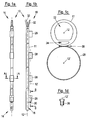
- Fig. 1a and 1b show a hose assembly 10 with a flexible disposable tube 11, wherein the Fig. 1b one opposite the Fig. 1a represents 90 ° rotated about a longitudinal axis 12 view.
- the tubing assembly 10 has a distal end 14 and a proximal end 16.
- a fixation sleeve 26 is attached to the disposable tube 11.
- the fixation cuff 26 is further proximal than an opening 18 and an exit opening 20 so that the distal end of an endoscope (not shown) to be inserted into the fixation cuff 26 is in visual contact with the openings laterally attached to the disposable tube 11 with respect to the longitudinal axis 12 18, 20 stands.
- the opening 18 and the outlet opening 20 are connected to a working channel 22 and an optional flushing channel 24 (shown in FIG Fig. 1c ) of the disposable tube 11 in conjunction.
- the outlet opening 20 of the flushing channel 24 is arranged at a small distance distally offset to the fixing collar 26.
- rinsing liquid can be sprayed onto the optics of the endoscope to clean them and to remove, for example, disturbing secretions.
- air may also be passed through the flushing channel 24 to not only blow open the optics of the endoscope, but also to inflate the cavity to be examined by air insufflation so that a wall of, for example, the stomach or esophagus can be better observed.
- the opening 18 of the working channel 22 is offset relative to the fixing sleeve 26 further distally than the outlet opening 20. Since it is also arranged with respect to the longitudinal axis 12 of the disposable tube 11 on the fixing sleeve 26 side facing, it is for example possible to suck up secretions or other substances in the area directly in front of the endoscope.
- guide loops 28 are attached to the disposable tube 11 of the tube assembly 10. They are arranged at regular intervals, this being merely a special embodiment.
- Fig. 1c illustrates the structure of the hose assembly based on a cross section along the section line AA of Fig. 1a , In the upper part of the Fig. 1c the cross section of the disposable tube 11 can be seen.
- the disposable tube 11 comprises the working channel 22 and the optional flushing channel 24.
- the working channel 22 has a substantially larger cross-sectional area than the flushing channel 24. Depending on requirements, a different distribution may be selected.
- the cross-section of the working channel 22 can be simplified by a combination of a circular arc section with a part of a trapezoid with rounded corners describe.
- the deviation from a circular cross-section of the working channel 22 for a given outer diameter of the disposable tube 11 allows a more efficient passage of liquid or pieces of tissue.
- a work tool with a circular cross-section in such a shaped working channel 22 can be moved more easily, since the contact surface to the inner walls of the working channel 22 is smaller than in the case of a circular cross-section and thus less friction occurs.
- the side walls of the disposable tube which laterally delimit the working channel 22 are designed to be relatively thick, for example with respect to the wall section of the disposable tube 11 opposite the flushing channel 24. This results in a bending of the disposable tube 11 by means of the endoscope (see. Fig. 5c ) prevents collapse of the working channel 22.
- the flushing channel 24 is optimized in its cross-sectional shape and size such that a sufficient supply of flushing liquid for cleaning the optics of the endoscope can always be supplied with optimal cross-sectional area utilization of the disposable tube 11.
- the flushing channel 24 is located between the working channel 22 and the guide loops 28, d. H. on a line connecting the longitudinal axis 12 of the disposable tube 11 and a longitudinal axis 12 'extending parallel thereto, which extends along the longitudinal axes of the guide loops 28 and the fixing collar 26.
- the lower part of the picture in Fig. 1c is taken from the cross section of one of the guide loops 28.
- This has a circular cross section, which serves to receive the endoscope.
- the endoscope can move in particular in the longitudinal direction.
- the guide loops 28 thus serve to hold the disposable tube 11 of the tube assembly 10 in the lateral direction in close spatial proximity to the endoscope, but not firmly connect them together.
- the guide loop 28 is glued to the disposable tube, as indicated by the adhesive connection 30.
- the type of connection can be chosen freely, for example, a welded connection or a shrink connection is alternatively possible.
- a one-piece design of the disposable tube 11 and the guide loops 28 is conceivable. The same applies to the fixing collar 26.
- Fig. 1d shows a cross section through the Fixiermanschette 26 along the section line BB of Fig. 1b , It can be clearly seen that the inner diameter of the fixation cuff 28 is distally smaller than it is proximal.
- the fixing collar 26 preferably consists of an elastic material, so that the inner radius-reduced area of the fixing collar 26 is widened by the insertion of the distal end of the endoscope. This creates a frictional connection between the Fixiermanschette 26 - which is indeed firmly connected to the disposable tube 12 - and the endoscope. A reliable fixation is thus ensured.
- the working channel 22 and the flushing channel 24 are connected to separate connecting tubes 32, which serve to supply / discharge of liquids and / or tissue parts.
- the flushing channel 24 may in the embodiment according to Fig. 1a to 1d also omitted, especially for applications of the hose assembly 10 in the ear, nose and throat (ENT) area.
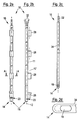
- FIG Fig. 2a and 2b A somewhat modified embodiment of the hose assembly 10 is shown in FIG Fig. 2a and 2b shown (not an embodiment of the invention).
- the two embodiments are similar, particularly with respect to the cross-sectional shape of the tube assembly 10.
- the opening 18 of the working channel 22 is not attached laterally, but is axially aligned with respect to the longitudinal axis 12.
- the distal end of the disposable tube 11 cut perpendicular to the longitudinal axis 12.
- this embodiment in the present form can also be used, for example, for extracting substances.
- this embodiment is particularly suitable for guiding work tools through the working channel 22. This is especially true when the flushing channel 24 with the outlet opening 20 is omitted.
- the working channel 22 but also similar to in Fig. 1a and b shown embodiment, when an inner tube 34 is used, which is guided through the working channel 22.
- Such inner tube 34 is in Fig. 2c shown. At its proximal end 16 it is connected to a connecting tube 32.
- the distal end 16 of the inner tube 34 is similar to the tip of FIG Fig. 1a and 1b illustrated embodiment of the hose assembly 10.
- the inner tube 34 has a laterally disposed slot which represents the opening 18.
- the opening 18 of the inner tube 34 is shown in more detail in FIG Fig. 2d illustrated, wherein the dashed line symbolizes the wall thickness of the inner tube 34.
- the opening 18 is dimensioned such that it has the greatest possible width in a direction perpendicular to the longitudinal axis 12, so that even relatively large pieces of tissue or secretion lumps can be sucked off.
- the advantage of this embodiment in combination with the use of the inner tube 34 is that the opening 18 can be positioned almost arbitrarily relative to the fixation cuff 26 by turning and pushing the inner tube 34, and thus relative to the endoscope. For example, a larger area of the examination area can be achieved with the opening 18 with unchanged position of the disposable tube 11 and the endoscope. The treating physician is given such a flexible working device in the hand.
- FIG Fig. 3a Another embodiment of the hose assembly 10 is shown in FIG Fig. 3a shown. It shows a disposable tube 11 which is provided with guide loops 28 and a fixing collar 26.
- the proximal guide loop 28 has a significantly greater longitudinal extent than the distal guide loop 28 of the embodiments discussed above.
- the distal end of the disposable tube 11 is flush with the distal end of the Fixiermanschette 26.
- a closure cap 36 eg Fig. 3b ).
- the end cap 36 is attached to the disposable tube 11 or otherwise connected to this.
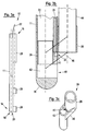
- FIG Fig. 3b A sectional view through the distal end 14 of the tube assembly 10 is shown in FIG Fig. 3b shown.
- the disposable tube 11 has a working channel 22 and a flushing channel 24.
- a connecting sleeve 38 is inserted, in turn, the end cap 36 is attached.
- the connecting sleeve 38 and the end cap 36 may also be made in one piece.
- the end cap 36 has a groove 40. If the end cap 36 is connected to the disposable tube 11, this groove 40 forms the outlet opening 20 of the flushing channel 24. Furthermore, the end cap 36 has a channel 42 which communicates with the working channel 22 and which comprises a laterally arranged opening 18. Functionally and with respect to the arrangement of the openings 18, 20 of the channels 22, 24 therefore resembles in the Fig. 3b illustrated embodiment of the hose assembly 10 of in Fig. 1a and 1b illustrated embodiment.
- An integral part of the end cap 36 is also the fixing collar 26, which rotatably and axially fixedly connects an endoscope 44 with the end cap 36 and thus the disposable tube 11.
- the detailed illustration of the distal end 14 of the tube assembly 10 illustrates the spatial proximity of the openings 18, 20 to the distal end of the endoscope 44.
- Effluent flushing liquid can be efficiently injected onto the endoscope optic through the outlet opening 20 in order to clean it. In the visual field of the optics of the endoscope, however, secretion or the like can be simply sucked through the opening 18.
- the end cap 36 is an easy-to-manufacture component and may, for example, have various variations in the shapes and orientations of the apertures 18, 20. Also, the openings 18, 20 may be arranged on different sides.
- the inner tube 34 may also be provided with such an end cap, both in the embodiment of the inner tube 34 with only one working channel 22 and in the embodiment of the inner tube 34 with a working channel 22 and a flushing channel 24th
- FIG. 3c A perspective view of such an end cap is in Fig. 3c shown.
- the end cap 36 of Fig. 3c has two connecting webs 46 which connects the fixing collar 26 with the part of the end cap 36 containing the openings 18, 20.
- the location of the connecting webs 46 relative to the other elements of the end cap 36 is in Fig. 3b indicated by obliquely to the longitudinal axes 12, 12 'extending dashed lines.
- FIG. 4a A slightly different embodiment of a end cap 36 illustrates Fig. 4a ,
- the end cap 36 is attached to the disposable tube 11, so that can be dispensed with a connection sleeve 38.
- the rest of the structure of the end cap 36 is similar to that of Fig. 3b shown embodiment.
- Fig. 4b shows a perspective view of the in Fig. 4a
- the embodiment of the end cap 36 The groove 40 forming the outlet opening 20 of the flushing channel 24 is again arranged at the distal end of the fixing collar 26, so that the groove 40 in the perspective shown in FIG Fig. 4b not visible.
- FIG Fig. 5a An advantageous modification of the hose assembly 10 is shown in FIG Fig. 5a shown (not an embodiment of the invention).
- the essential features of the distal end 14 of the hose assembly 10, such as the opening 18, the opening 20 of the optional flushing channel, the fixing collar 26 and the guide loop 28, have already been described in detail above.
- the illustrated embodiment additionally has a coil spring 48 embedded in the disposable tube 11, such as Fig. 5b can be seen.
- Fig. 5b shows a section perpendicular to a section line CC of Fig. 5a ,
- the coil spring 48 extends over a portion of the distal portion of the tubing assembly 10 that is proximally offset relative to the exit port 20 of the flushing channel 24. It is bendable, that is elastically bendable perpendicular to the longitudinal axis 12, wherein its cross-sectional shape changes only insignificantly at a bend. It is thereby achieved that at a curvature of the hose assembly 10, the channels 22, 24 are not compressed, whereby, for example, the supply / supply of liquid and / or tissue would be prevented.
- Such a reinforcing element in the form of a coil spring 48 - wherein other reinforcing elements can be used - is particularly advantageous in situations when the endoscope is brought into inversion.
- the endoscope 44 is strongly curved, so that the endoscope optics looks "backwards" to the proximal (see Fig. 5c ).
- the coil spring 48 Without the coil spring 48, the tube cross section of the disposable tube 11 would be squeezed together.
- the supply, for example, of rinsing liquid would be interrupted.
- the same supporting effect can be achieved for example by a the disposable tube 11 sections surrounding coil spring.
- the guide loops 28 should allow a relative movement between the endoscope 44 and the disposable tube 11. If the connection between the guide loops 28 and the endoscope 44 were fixed and no longitudinally displaceable movement were permitted, then due to the different radii of curvature of the disposable tube 11 and the endoscope 44, strong stretching loads in the longitudinal direction would occur in the disposable tube 11 or in the endoscope 44, on the one hand the On the other hand, could also cause collapse of the cross sections of the channels 22, 24, or could cause damage to the Bowden cables of the endoscope 44.
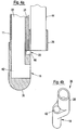
- Fig. 6a shows the distal end 14 of one embodiment of the tube assembly 10 (not an embodiment of the invention).
- the working channel 22 and the optional flushing channel 24 of the disposable tube 11 are not shown because their arrangement is of secondary importance to the aspect to be described below.
- the arrows D, E indicate that both the flushing channel 24 and the working channel 22 through the lateral openings 20 and 18 of the disposable tube 11 are in communication with a region in front of the endoscope 44.
- the distal end 14 of the tube assembly 10 is closed by a end piece 36a.
- the two in the longitudinal direction of the disposable tube 11 mutually offset openings 18, 20 are not closed by the end piece 36a.
- Fig. 6b shows another embodiment of the hose assembly 10 (not an embodiment of the invention), which, however, relies on the same disposable tube 11, as in Fig. 6a shown embodiment.
- the cap or peg-like end piece 36a of the Fig. 6a was here replaced by a hollow cylindrical end piece 36b, which leaves the axial opening at the distal end 14 of the disposable tube 11 open.
- the end piece 36b closes the lateral working channel opening 18, so that the working channel 22 is now in communication with a region in front of the distal end 14 of the hose assembly 10.
- the optional lateral outlet opening 20 of the flushing channel 24 is still open.
- the end pieces 36a, 36b may also be designed so that they are attached to the disposable tube 11 - not plugged in as in Fig. 6a and 6b - or otherwise attached to this.
- Corresponding end pieces 36a, 36b can also be found in embodiments of the hose assembly 10 with inner tube 34 use.
- the hose assembly 10 of the present invention may include more than one purge passage 24, as in FIG Fig. 7a is shown.
- This embodiment has two flushing channels 24, 24 ', which are not directly between the working channel 22 and the fixing device - here a Fixiermanschette 26' with a sectionally different from a circle cross-section - are arranged.
- the flushing channels 24, 24 ' are laterally offset relative to a connecting line FF between the longitudinal axis 12 of the disposable tube 11 and the longitudinal axis 12' of the fixing collar 26 '. They are arranged symmetrically on both sides of the connecting line FF.
- the disposable tube 11 in such a configuration for a given diameter of the working channel 22 (lumen) have a smaller wall thickness.
- the outlet openings 20 of the flushing channels 24, 24 'need not be aligned in the longitudinal direction of the hose assembly 10 or lie in a common cross-sectional plane, but may be arranged arbitrarily to different areas - possibly also independently - to be able to flush.
- FIG Fig. 7b An example of an embodiment with a single offset flushing channel 24 is shown in FIG Fig. 7b shown.
- the area of the flushing channel 24 'of the Fig. 7a was slammed into the working channel. This area can be used, for example, to guide another thin tube or work equipment / instruments.
- Fig. 8a to 8c show various embodiments of a fastener through which the guide loops 28 and / or the Fixiermanschette 26, 26 'can be provided.
- the fastener is formed by a single-piece band 50 which is easy to manufacture and which surrounds both the disposable tube 11 and the endoscope 44.
- the band 50 may be releasably or firmly connected to the disposable tube 11.
- band is not to suggest that the band 50 must be flexible, for example, as a type of rubber band. It may also be, for example, a relatively rigid plastic component.
- the band 50 acts as a fixing collar 26, 26 ', then it fixes the endoscope 44 in a rotationally fixed and in the axial direction. If it serves only to guide the endoscope 44, then it is designed such that the endoscope 44 can move relative to the disposable tube 11.
- Fig. 8a shows a simple variant of the band 50. It forms a single loop 54, in which the disposable tube 11 and the endoscope 44 are arranged.
- the loop 54 has substantially the shape of an "O".
- the band 50 of the Fig. 8b a waist 52 through which two loops 54, 54 'are defined so that the band 50 forms a shape similar to an imperfect "8".
- that is Constriction in the central region of the band 50 is not complete, whereby a connection between the two loops 54, 54 'is made.
- the loop 54 of the disposable tube 11 is arranged, while the loop 54 'receives the endoscope 44.
- the advantage of the waisted band 50 is that mutual twisting of the disposable tube 11 and the endoscope 44 is prevented. Such twisting causes problems, in particular with an inversion of the endoscope 44.
- Fig. 8c shows a band 50 with a sidecut 52, the loops 54, 54 'are separated by a web 53, whereby the shape of an "8" is formed.
- the band 50 may also have only the web 53 so that the outer contour of the band 50 corresponds to an "O", as in the case of FIG Fig. 8a shown embodiment of the band 50th
Landscapes
- Health & Medical Sciences (AREA)
- Life Sciences & Earth Sciences (AREA)
- Surgery (AREA)
- Engineering & Computer Science (AREA)
- Heart & Thoracic Surgery (AREA)
- Biophysics (AREA)
- Veterinary Medicine (AREA)
- Public Health (AREA)
- General Health & Medical Sciences (AREA)
- Animal Behavior & Ethology (AREA)
- Biomedical Technology (AREA)
- Medical Informatics (AREA)
- Physics & Mathematics (AREA)
- Molecular Biology (AREA)
- Radiology & Medical Imaging (AREA)
- Pathology (AREA)
- Optics & Photonics (AREA)
- Nuclear Medicine, Radiotherapy & Molecular Imaging (AREA)
- General Engineering & Computer Science (AREA)
- Otolaryngology (AREA)
- Mechanical Engineering (AREA)
- Pulmonology (AREA)
- Physiology (AREA)
- Hematology (AREA)
- Anesthesiology (AREA)
- Endoscopes (AREA)
Description
- Die Erfindung betrifft das Gebiet der Endoskopie, insbesondere eine Schlauchanordnung zur Befestigung an einem Endoskop.
- In vielen Teilbereichen der Medizin, insbesondere in der Gastroenterologie, ist die Endoskopie eine weit verbreitete und erfolgreiche Methode in der Diagnostik und bei der Behandlung einer Vielzahl von Erkrankungen. Dabei hat es sich als zweckmäßig erwiesen, bildgebende Endoskope mit Schlauchanordnungen zu versehen, die einen Kanal oder mehrere Kanäle beispielsweise zur Führung von Arbeitsgeräten aufweisen. Allerdings erweisen sich herkömmliche Schlauchanordnungen der vorgenannten Art häufig als unpraktisch, da die Befestigungsmittel zur Verbindung des Endoskops mit der Schlauchanordnung oft raumgreifend gestaltet sind und/oder die Bedienung des Endoskops behindern. Weiterhin ist die Anordnung der Kanäle häufig sehr spezialisiert konzipiert, so dass für jeden Anwendungszweck eine entsprechende Schlauchanordnung gewählt werden muss.
- Aus dem Dokument
EP 1 477 104 A ist eine Schlauchanordnung für ein Endoskop gemäß dem Oberbegriff des Anspruchs 1 bekannt. - Das Dokument
WO 01/87144 A1 - Weitere Schlauchanordnungen für Endoskope sind aus den Dokumenten
WO 2004/103157 A ,WO2006/033671 A undUS-A-5 702 347 bekannt. - Es ist die Aufgabe der Erfindung, eine Schlauchanordnung für ein Endoskop zu schaffen, die eine zuverlässige und platzsparende Befestigung an dem Endoskop ermöglicht. Das Befestigen des Endoskops soll außerdem einfach zu bewerkstelligen sein.
- Die Lösung dieser Aufgabe erfolgt durch die Merkmale des Anspruchs 1.
- Die erfindungsgemäße Schlauchanordnung für ein Endoskop umfasst zumindest einen Einwegschlauch, der einen Arbeitskanal umgibt. Weiterhin umfasst die Schlauchanordnung Endoskopbefestigungsmittel zum Befestigen des Einwegschlauchs an einem Endoskop. Die Endoskopbefestigungsmittel weisen eine Fixiereinrichtung auf, durch die der Einwegschlauch am distalen Ende des Endoskops drehfest und axial fest fixierbar ist. Die Endoskopbefestigungsmittel weisen ferner wenigstens eine Führungseinrichtung auf, durch die der Einwegschlauch an einem jeweiligen vom distalen Ende des Endoskops beabstandeten Abschnitt des Endoskops verschieblich befestigbar ist.
- Mit anderen Worten wird die Verbindung zwischen dem Endoskop und der erfindungsgemäßen Schlauchanordnung durch Endoskopbefestigungsmittel hergestellt, die einerseits eine Fixiereinrichtung, andererseits eine Führungseinrichtung umfassen. Die Fixierungseinrichtung stellt eine feste Verbindung zwischen dem Endoskop und der Schlauchanordnung her, wodurch Relativbewegungen zwischen dem distalen Ende des Endoskops und der Schlauchanordnung unterbunden werden. Hierdurch ist gewährleistet, dass eine in der Umgebung der Fixiereinrichtung angeordnete Austrittsöffnung des Arbeitskanals im Einsatz des Endoskops und insbesondere auch bei einer Krümmung des Endoskops (z. B. aufgrund einer Betätigung eines Bowdenzugs) ihre Position relativ zu dem distalen Ende des Endoskops stets beibehält. Somit ist eine definierte Position einer seitlichen oder axialen Öffnung des Arbeitskanals relativ zu dem distalen Ende des Endoskops sichergestellt, was beispielsweise für das Absaugen von Sekreten oder für eine Probenentnahme mittels einer durch den Arbeitskanal geführten Biopsiezange wichtig ist, wenn zugleich eine Beobachtung mittels des Endoskops erfolgen soll.
- Demgegenüber erlaubt die Führungseinrichtung eine Relativbewegung zwischen dem Endoskop und der Schlauchanordnung. Dies ermöglicht Ausgleichsbewegungen in Längsrichtung (längsverschiebliche Befestigung) und/oder in Umfangsrichtung der Schlauchanordnung (drehbewegliche Befestigung), die aufgrund von während der Benutzung auftretenden Biegungen oder Krümmungen entlang der Einheit aus Endoskop und Schlauchanordnung erforderlich sind. Darüber hinaus wird das Befestigen des Endoskops vereinfacht, da eine kraftschlüssige Fixierung in der Regel nur an einem Punkt des Endoskops - nämlich an dessen distalen Ende - erfolgt.
- Die Schlauchanordnung umfasst ferner eine Abschlusskappe, welche mit dem distalen Ende des Einwegschlauchs verbunden ist. Die Schlauchanordnung ist somit in axialer Richtung zumindest zweiteilig. Eine solche Abschlusskappe kann kostengünstig hergestellt werden - beispielsweise als Spritzgussteil aus Kunststoff - und eröffnet zusätzliche Möglichkeiten, die Schlauchanordnung an die jeweils vorliegenden Bedürfnisse anzupassen.
- Die Abschlusskappe ist fest mit der Fixiereinrichtung verbunden. Wie bereits vorstehend erläutert, besteht zwischen der Fixiereinrichtung und dem Endoskop eine drehfeste und axial feste Verbindung. Ist nun die Fixereinrichtung fest mit der Abschlusskappe verbunden, ist besonders zuverlässig sichergestellt, dass die Abschlusskappe bei endoskopischen Untersuchungen und/oder Behandlungen nicht verloren geht. Außerdem ist dadurch die relative Lage der Abschlusskappe bezüglich der Optik des Endoskops fest definiert, was bei verschiedenen Untersuchungs-/Behandlungsmethoden vorteilhaft sein kann.
- Gemäß einer vorteilhaften Weiterbildung umgibt der Einwegschlauch zusätzlich wenigstens einen Spülkanal, wobei die Schlauchanordnung eine Austrittsöffnung des Spülkanals aufweist, die bezüglich der Fixiereinrichtung für das distale Ende des Endoskops nach distal versetzt angeordnet ist. Die Schlauchanordnung weist ferner eine Öffnung des Arbeitskanals auf, die bezüglich der Fixiereinrichtung ebenfalls nach distal versetzt angeordnet ist. Somit ist beispielsweise sichergestellt, dass eine am distalen Ende des Endoskops befindliche Optik mittels einer durch den Spülkanal geführten Spülflüssigkeit stets zuverlässig gespült werden kann. Die Schlauchanordnung umgibt in diesem Fall also zumindest zwei Kanäle, einen Arbeitskanal und einen Spülkanal. Die Austrittsöffnung des Spülkanals und die Öffnung des Arbeitskanals sind in einem Abschnitt der Schlauchanordnung angeordnet, der in distaler Richtung der Schlauchanordnung über die Fixiereinrichtung für das distale Endes des Endoskops hinaus ragt, wodurch ein effizientes Spülen einer am distalen Ende des Endoskops angeordneten Optik mittels einer aus der Austrittsöffnung des Spülkanals austretenden Spülflüssigkeit möglich ist. Außerdem können mittels des Arbeitskanals durchgeführte Tätigkeiten visuell durch das Endoskop kontrolliert werden.
- Gemäß einer Ausführungsform der erfindungsgemäßen Schlauchanordnung umfasst diese einen einzigen Einwegschlauch, an dem der Arbeitskanal und gegebenenfalls der Spülkanal ausgebildet sind.
- Es ist bevorzugt, wenn die Abschlusskappe einstückig mit der Fixiereinrichtung ausgebildet ist.
- Bei einer Weiterbildung der Abschlusskappe sind die Austrittsöffnung des Spülkanals und/oder die Öffnung des Arbeitskanals an der Abschlusskappe ausgebildet.
- Es kann bei vorteilhaften Ausführungsformen der erfindungsgemäßen Schlauchanordnung mit Abschlusskappe vorgesehen sein, dass die Öffnung des Arbeitskanals und/oder die Austrittsöffnung des gegebenenfalls vorhandenen Spülkanals seitlich angeordnet sind, wodurch beispielsweise ein Spülen der Endoskopoptik mittels über den Spülkanal zugeführter Spülflüssigkeit ermöglicht wird. Unter anderem für diesen Zweck ist der Spülkanal - bezogen auf einen Querschnitt der Schlauchanordnung - vorzugsweise zwischen dem Arbeitskanal und den Endoskopbefestigungsmitteln angeordnet.
- Gemäß einer Ausführungsform ist der gegebenenfalls vorhandene Spülkanal in einem Querschnitt der Schlauchanordnung - bezogen auf eine Verbindungslinie zwischen einer Längsachse des Einwegschlauchs und einer Längsachse der Endoskopbefestigungsmittel - seitlich versetzt angeordnet. Anstelle eines einzigen Spülkanals kann die Schlauchanordnung zwei oder mehr Spülkanäle aufweisen. Die Austrittöffnungen der Spülkanäle können in axialer Richtung der Schlauchanordnung versetzt zueinander angeordnet sein. Ein relativer Versatz der Austrittöffnungen in radialer Richtung oder in Umfangsrichtung kann zusätzlich oder alternativ vorgesehen sein. Insbesondere sind die Spülkanäle - bezogen auf die vorstehend genannte Verbindungslinie - symmetrisch angeordnet.
- Gemäß einer Ausführungsform der erfindungsgemäßen Schlauchanordnung umfasst die Führungseinrichtung mehrere Halteelemente, die beabstandet voneinander entlang der Länge des Einwegschlauchs angeordnet sind, da eine durchgehende, d.h. unterbrechungsfreie, Führungseinrichtung ist in vielen Fällen nicht notwendig. Eine mehrere Halteelemente umfassende Führungseinrichtung erlaubt zudem ein leichteres Einführen des Endoskops in die Führungseinrichtung und bedeutet bei einer Relativbewegung von Endoskop und Einwegschlauch im Betrieb geringe zu überwindende Reibungskräfte. Insbesondere können zwei bis drei im Wesentlichen identische Halteelemente vorgesehen sein, beispielsweise bei einer Endoskoplänge von 35 cm. Bei einer Endoskoplänge von 75 cm können beispielsweise drei bis fünf Halteelemente vorgesehen sein, bei einer Endoskoplänge von 100 cm beispielsweise fünf bis sieben Halteelemente.
- Es ist bevorzugt, wenn die Führungseinrichtung wenigstens eine im Wesentlichen hohlzylinderförmig ausgebildete Schlaufe aufweist. Derartige Schlaufen sind leicht zu fertigen bzw. anzuformen, stellen gleichzeitig aber auch eine zuverlässige Führung der Schlauchanordnung sicher.
- Die Führungseinrichtung und/oder die Fixiereinrichtung können als einstückiges Befestigungselement ausgebildet sein, das den Einwegschlauch und das Endoskop umgibt, und das eine Einwegschlauchaufnahme und eine Endoskopaufnahme aufweist, die durch eine Einschnürung und/oder einen Steg definiert sind, die bzw. der zwischen der Einwegschlauchaufnahme und der Endoskopaufnahme angeordnet ist.
- Die Fixiereinrichtung kann derart gestaltet sein, dass eine kraftschlüssige, insbesondere reibschlüssige Verbindung zwischen dem Einwegschlauch und dem Endoskop hergestellt wird. Eine vorteilhafte Ausgestaltung der Fixiereinrichtung umfasst eine in axialer Richtung beidseitig geöffnete Manschette.
- Gemäß einer Ausführungsform der Schlauchanordnung weist der Einwegschlauch zumindest ein Verstärkungselement auf. Das Verstärkungselement ist krümmbar, da es in erster Linie zur Stabilisierung des Querschnitts der Kanäle dient, die beispielsweise bei einer starken Krümmung des Einwegschlauchs zusammengequetscht werden würden, und weniger zur Stabilisierung der Längsachse der Schlauchanordnung, obwohl dieser Aspekt in speziell gelagerten Fällen auch genutzt werden kann. Die Steifigkeit des Querschnitts des Verstärkungselements und die Elastizität gegenüber Kräften senkrecht zu der Längsachse des Verstärkungselements kann entsprechend den Anforderungen gewählt werden.
- Das Verstärkungselement ist insbesondere in einem distalen Bereich der Schlauchanordnung angeordnet, der relativ zu der Austrittsöffnung des gegebenenfalls vorhandenen Spülkanals nach proximal versetzt angeordnet ist, da hier bei einer entsprechender Betätigung des Endoskops die stärksten Krümmungen zu erwarten sind. Es können aber auch zusätzliche Verstärkungselemente in weiteren kritischen Bereichen der Schlauchanordnung vorgesehen sein.
- Die Erfindung wird im Folgenden rein beispielhaft anhand vorteilhafter Ausführungsformen unter Bezugnahme auf die Zeichnungen beschrieben. Es zeigen:
- Fig. 1a
- eine schematische Darstellung einer Schlauchanordnung (keine Ausführungsform der Erfindung);
- Fig. 1b
- eine um 90° gedrehte Ansicht der Schlauchanordnung von
Fig. 1a ; - Fig. 1c
- einen Schnitt durch die Schlauchanordnung von
Fig. 1a entlang einer Schnittlinie AA; - Fig. 1d
- einen Schnitt durch eine Fixiermanschette der Schlauchanordnung entlang der Schnittlinie BB in
Fig. 1b ; - Fig. 2a
- eine schematische Darstellung einer weiteren Schlauchanordnung (keine Ausführungsform der Erfindung);
- Fig. 2b
- eine um 90° gedrehte Ansicht der Schlauchanordnung von
Fig. 2a ; - Fig. 2c
- eine schematische Darstellung einer Ausführungsform eines Innenschlauchs;
- Fig. 2d
- eine vergrößerte Ansicht des distalen Endes des Innenschlauchs von
Fig. 2c ; - Fig. 3a
- eine schematische Darstellung einer Ausführungsform der erfindungemäßen Schlauchanordnung;
- Fig. 3b
- eine schematische Schnittansicht einer Ausführungsform einer Abschlusskappe mit Fixiereinrichtung;
- Fig. 3c
- eine perspektivische Ansicht der Abschlusskappe von
Fig. 3b ; - Fig. 4a
- eine schematische Schnittansicht einer weiteren Ausführungsform einer Abschlusskappe mit Fixiereinrichtung;
- Fig. 4b
- eine perspektivische Ansicht der Abschlusskappe von
Fig. 4a ; - Fig. 5a
- eine schematische Darstellung einer Schlauchanordnung mit Verstärkungselement (keine Ausführungsform der Erfindung);
- Fig. 5b
- einen Schnitt durch die Schlauchanordnung von
Fig. 5a entlang einer Schnittlinie CC; - Fig. 5c
- ein Endoskop mit einer Schlauchanordnung in einer gekrümmten Anordnung,
- Fig. 6a und 6b
- jeweils einen Längsschnitt einer Schlauchanordnung mit einem Abschlussstück (keine Ausführungsform der Erfindung),
- Fig. 7a und 7b
- jeweils einen Querschnitt einer Schlauchanordnung mit zwei versetzt und symmetrisch angeordneten Spülkanälen bzw. mit einem versetzt angeordneten Spülkanal,
- Fig. 8a bis 8c
- verschiedene Ausführungsformen der Fixiereinrichtung und/oder der Führungseinrichtung in einer jeweiligen Querschnittsansicht.
-
Fig. 1a und 1b (keine Ausführungsform der Erfindung) zeigen eine Schlauchanordnung 10 mit einem flexiblen Einwegschlauch 11, wobei dieFig. 1b eine gegenüber derFig. 1a um 90° um eine Längsachse 12 verdrehte Ansicht darstellt. Die Schlauchanordnung 10 weist ein distales Ende 14 und ein proximales Ende 16 auf. In einem distalen Bereich der Schlauchanordnung 10 nahe dem distalen Ende 14 ist eine Fixiermanschette 26 an dem Einwegschlauch 11 befestigt. Die Fixiermanschette 26 ist weiter proximal angeordnet als eine Öffnung 18 und eine Austrittsöffnung 20, so dass das distale Ende eines in die Fixiermanschette 26 einzuführenden Endoskops (nicht gezeigt) in visuellem Kontakt mit den - bezüglich der Längsachse 12 - seitlich an dem Einwegschlauch 11 angebrachten Öffnungen 18, 20 steht. Die Öffnung 18 und die Austrittsöffnung 20 stehen mit einem Arbeitskanal 22 bzw. einem optionalen Spülkanal 24 (gezeigt inFig. 1c ) des Einwegschlauchs 11 in Verbindung. Wie denFig. 1a und 1b deutlich zu entnehmen ist, ist die Austrittsöffnung 20 des Spülkanals 24 in geringem Abstand nach distal versetzt zu der Fixiermanschette 26 angeordnet. Durch die räumliche Nähe und die schlitzartige Formgebung der somit als Düse wirkenden Austrittsöffnung 20 kann Spülflüssigkeit auf die Optik des Endoskops gesprüht werden, um diese zu reinigen und beispielsweise störendes Sekret zu entfernen. Alternativ hierzu kann auch Luft durch den Spülkanal 24 geführt werden, um nicht nur die Optik des Endoskops freizublasen, sondern um durch Luftinsuflation auch den zu untersuchenden Hohlraum aufzublasen, so dass eine Wand beispielsweise des Magens oder des Ösophagus besser beobachtet werden kann. - Die Öffnung 18 des Arbeitskanals 22 ist relativ zu der Fixiermanschette 26 weiter nach distal versetzt als die Austrittsöffnung 20. Da auch sie bezüglich der Längsachse 12 des Einwegschlauchs 11 auf der der Fixiermanschette 26 zugewandten Seite angeordnet ist, ist es beispielsweise möglich, Sekret oder andere Substanzen im Bereich direkt vor dem Endoskop abzusaugen.
- Neben der Fixiermanschette 26 sind Führungsschlaufen 28 an dem Einwegschlauch 11 der Schlauchanordnung 10 angebracht. Sie sind in regelmäßigen Abständen angeordnet, wobei dies lediglich eine spezielle Ausführungsform darstellt.
-
Fig. 1c verdeutlicht den Aufbau der Schlauchanordnung anhand eines Querschnitts entlang der Schnittlinie AA vonFig. 1a . Im oberen Teil derFig. 1c ist der Querschnitt des Einwegschlauchs 11 zu sehen. Der Einwegschlauch 11 umfasst - wie vorstehend bereits angesprochen - den Arbeitskanal 22 und den optionalen Spülkanal 24. Zur besseren Nutzung der Querschnittsfläche des Einwegschlauchs 11 sind weder der Arbeitskanal 22 noch der Spülkanal 24 kreisförmig ausgebildet. In der dargestellten Ausführungsform der Schlauchanordnung 10 weist der Arbeitskanal 22 eine wesentlich größere Querschnittsfläche auf als der Spülkanal 24. Je nach Bedarf kann eine davon abweichende Aufteilung gewählt werden. Der Querschnitt des Arbeitskanals 22 lässt sich vereinfacht durch eine Kombination eines Kreisbogenabschnitts mit einem Teil eines Trapezes mit abgerundeten Ecken beschreiben. Die Abweichung von einem kreisförmigen Querschnitt des Arbeitskanals 22 bei gegebenem Außendurchmesser des Einwegschlauchs 11 erlaubt eine effizientere Durchführung von Flüssigkeit oder Gewebestücken. Außerdem lässt sich ein Arbeitsgerät mit kreisförmigem Querschnitt in einem derartig geformten Arbeitskanal 22 leichter bewegen, da die Kontaktfläche zu den Innenwänden des Arbeitskanals 22 kleiner ist als im Fall eines kreisförmigen Querschnitts und somit weniger Reibung auftritt. - Insbesondere sind die den Arbeitskanal 22 seitlich begrenzenden Seitenwände des Einwegschlauchs beispielsweise bezüglich des dem Spülkanal 24 gegenüberliegenden Wandabschnitts des Einwegschlauchs 11 relativ dick ausgebildet. Hierdurch wird bei einem Krümmen des Einwegschlauchs 11 mittels des Endoskops (vgl.
Fig. 5c ) ein Kollabieren des Arbeitskanals 22 verhindert. - Der Spülkanal 24 ist in seiner Querschnittsform und -größe derart optimiert, dass stets eine ausreichende Zufuhr von Spülflüssigkeit zur Reinigung der Optik des Endoskops bei optimaler Querschnittsflächenausnutzung des Einwegschlauchs 11 geliefert werden kann. Der Spülkanal 24 liegt zwischen dem Arbeitskanal 22 und den Führungsschlaufen 28, d. h. auf einer Linie, die die Längsachse 12 des Einwegschlauchs 11 und eine parallel dazu verlaufende Längsachse 12' verbindet, die sich entlang der Längsachsen der Führungsschlaufen 28 und der Fixiermanschette 26 erstreckt.
- Der untere Teil des Bildes in
Fig. 1c wird von dem Querschnitt einer der Führungsschlaufen 28 eingenommen. Diese weist einen kreisförmigen Querschnitt auf, der zur Aufnahme des Endoskops dient. Innerhalb der Führungsschlaufe 28 kann sich das Endoskop insbesondere in Längsrichtung bewegen. Die Führungsschlaufen 28 dienen somit dazu, den Einwegschlauch 11 der Schlauchanordnung 10 in seitlicher Richtung in enger räumlicher Nähe zu dem Endoskop zu halten, sie allerdings nicht fest miteinander zu verbinden. Dies ist, wie vorstehend bereits erläutert, Aufgabe der Fixiermanschette 26. Die Führungsschlaufe 28 ist an den Einwegschlauch angeklebt, wie durch die Klebeverbindung 30 angedeutet ist. Die Art der Verbindung kann allerdings frei gewählt werden, beispielsweise ist alternativ eine Schweißverbindung oder eine Schrumpfverbindung möglich. Auch eine einstückige Ausführung des Einwegschlauchs 11 und der Führungsschlaufen 28 ist denkbar. Entsprechendes gilt für die Fixiermanschette 26. -
Fig. 1d zeigt einen Querschnitt durch die Fixiermanschette 26 entlang der Schnittlinie BB vonFig. 1b . Es ist deutlich zu erkennen, dass der Innendurchmesser der Fixiermanschette 28 distal kleiner ist als proximal. Vorzugsweise besteht die Fixiermanschette 26 aus einem elastischem Material, so dass durch das Einführen des distalen Endes des Endoskops der innenradiusreduzierte Bereich der Fixiermanschette 26 geweitet wird. Dadurch entsteht eine reibschlüssige Verbindung zwischen der Fixiermanschette 26 - die ja fest mit dem Einwegschlauch 12 verbunden ist - und dem Endoskop. Eine zuverlässige Fixierung ist somit sichergestellt. - Am proximalen Ende des Einwegschlauchs 11 sind der Arbeitskanal 22 und der Spülkanal 24 mit separaten Verbindungsschläuchen 32 verbunden, die zur Zu-/Abfuhr von Flüssigkeiten und/oder Gewebeteilen dienen.
- Der Spülkanal 24 kann bei der Ausführungsform gemäß
Fig. 1a bis 1d auch entfallen, insbesondere für Anwendungen der Schlauchanordnung 10 im Hals-Nasen-Ohren-Bereich (HNO). In diesem Fall entfällt die inFig. 1a und 1b gezeigte Austrittsöffnung 20. - Eine etwas abgewandelte Ausführungsform der Schlauchanordnung 10 ist in
Fig. 2a und 2b gezeigt (keine Ausführungsform der Erfindung). In vielen Aspekten ähneln sich die beiden Ausführungsformen, insbesondere hinsichtlich der Querschnittsform der Schlauchanordnung 10. Im distalen Bereich liegt eine Übereinstimmung hinsichtlich der Fixiermanschette 26 und der Austrittsöffnung 20 vor. Die Öffnung 18 des Arbeitskanals 22 ist allerdings nicht seitlich angebracht, sondern ist bezüglich der Längsachse 12 axial ausgerichtet. Mit anderen Worten ist das distale Ende des Einwegschlauchs 11 senkrecht zur Längsachse 12 abgeschnitten. Einerseits kann auch diese Ausführungsform in der vorliegenden Form beispielsweise zum Absaugen von Substanzen verwendet werden. Andererseits eignet sich diese Ausführungsform aber insbesondere zum Führen von Arbeitsgerätschaften durch den Arbeitskanal 22. Dies gilt insbesondere, wenn der Spülkanal 24 mit der Austrittsöffnung 20 entfällt. Optional kann der Arbeitskanal 22 aber auch ähnlich der inFig. 1a und b gezeigten Ausführungsform genutzt werden, wenn ein Innenschlauch 34 verwendet wird, der durch den Arbeitskanal 22 geführt wird. - Ein derartiger Innenschlauch 34 ist in
Fig. 2c gezeigt. An seinem proximalen Ende 16 ist er mit einem Verbindungsschlauch 32 verbunden. Das distale Ende 16 des Innenschlauchs 34 ähnelt der Spitze der inFig. 1a und 1b dargestellten Ausführungsform der Schlauchanordnung 10. So verfügt der Innenschlauch 34 über ein seitlich angeordnetes Langloch, welches die Öffnung 18 darstellt. Die Öffnung 18 des Innenschlauchs 34 ist detaillierter inFig. 2d dargestellt, wobei die gestrichelte Linie die Wandstärke des Innenschlauchs 34 symbolisiert. Die Öffnung 18 ist derart dimensioniert, dass sie in einer Richtung senkrecht zur Längsachse 12 größtmögliche Breite aufweist, so dass auch relativ große Gewebestücke bzw. Sekretklumpen abgesaugt werden können. - Der Vorteil dieser Ausführungsform in Kombination mit der Verwendung des Innenschlauchs 34 liegt darin, dass die Öffnung 18 durch Drehen und Hin- und Herschieben des Innenschlauchs 34 fast beliebig relativ zu der Fixiermanschette 26 - und damit relativ zu dem Endoskop - positioniert werden kann. Beispielsweise kann so bei unveränderter Lage des Einwegschlauchs 11 bzw. des Endoskops ein größerer Bereich des Untersuchungsgebiets mit der Öffnung 18 erreicht werden. Dem behandelnden Arzt wird so ein flexibles Arbeitsgerät an die Hand gegeben.
- Eine weitere Ausführungsform der Schlauchanordnung 10 ist in
Fig. 3a gezeigt. Sie zeigt einen Einwegschlauch 11, der mit Führungsschlaufen 28 und einer Fixiermanschette 26 versehen ist. Die proximale Führungsschlaufe 28 weist eine deutlich größere Längserstreckung auf als die distale Führungsschlaufe 28 der vorstehend behandelten Ausführungsformen. Ein weiterer Unterschied zu den in denFig. 1a und 1b und2a und 2b gezeigten Ausführungsformen liegt darin, dass das distale Ende des Einwegschlauchs 11 bündig mit dem distalen Ende der Fixiermanschette 26 abschließt. In das distale Ende des Einwegschlauchs 11, der in diesem Fall einen Arbeitskanal 22 und optional einen Spülkanal 24 umfasst, kann eine Abschlusskappe 36 (z.B.Fig. 3b ) eingeführt werden. Es können auch Ausführungsformen vorgesehen sein, bei denen die Abschlusskappe 36 auf den Einwegschlauch 11 aufgesteckt oder anderweitig mit diesem verbunden wird. - Eine Schnittansicht durch das distale Ende 14 der Schlauchanordnung 10 ist in
Fig. 3b gezeigt. Der Einwegschlauch 11 weist einen Arbeitskanal 22 und einen Spülkanal 24 auf. In den Arbeitskanal 22 ist eine Verbindungshülse 38 eingesteckt, auf die wiederum die Abschlusskappe 36 aufgesteckt ist. Die Verbindungshülse 38 und die Abschlusskappe 36 können auch einstückig ausgeführt sein. - Die Abschlusskappe 36 weist eine Nut 40 auf. Ist die Abschlusskappe 36 mit dem Einwegschlauch 11 verbunden, bildet diese Nut 40 die Austrittsöffnung 20 des Spülkanals 24. Weiterhin weist die Abschlusskappe 36 einen Kanal 42 auf, der mit dem Arbeitskanal 22 in Verbindung steht und der eine seitlich angeordnete Öffnung 18 umfasst. Funktionell und bezüglich der Anordnung der Öffnungen 18, 20 der Kanäle 22, 24 ähnelt daher die in
Fig. 3b dargestellte Ausführungsform der Schlauchanordnung 10 der inFig. 1a und 1b dargestellten Ausführungsform. - Ein integraler Bestandteil der Abschlusskappe 36 ist weiterhin die Fixiermanschette 26, die ein Endoskop 44 drehfest und axial fest mit der Abschlusskappe 36 und damit dem Einwegschlauch 11 verbindet.
- Die detaillierte Darstellung des distalen Endes 14 der Schlauchanordnung 10 verdeutlicht die räumliche Nähe der Öffnungen 18, 20 zu dem distalen Ende des Endoskops 44. Durch die Austrittsöffnung 20 kann effizient Spülflüssigkeit auf die Endoskopoptik gespritzt werden, um diese zu reinigen. Im Gesichtsfeld der Optik des Endoskops kann hingegen durch die Öffnung 18 Sekret oder dergleichen einfach abgesaugt werden.
- Die Abschlusskappe 36 ist ein einfach herzustellendes Bauteil und kann beispielsweise verschiedene Variationen der Formen und Orientierungen der Öffnungen 18, 20 aufweisen. Auch können die Öffnungen 18, 20 an unterschiedlichen Seiten angeordnet sein. Der Innenschlauch 34 kann ebenfalls mit einer solchen Abschlusskappe versehen sein, sowohl bei der Ausführungsform des Innenschlauchs 34 mit lediglich einem Arbeitskanal 22 als auch bei der Ausführungsform des Innenschlauchs 34 mit einem Arbeitskanal 22 und einem Spülkanal 24.
- Eine perspektivische Ansicht einer solchen Abschlusskappe ist in
Fig. 3c gezeigt. Die Abschlusskappe 36 derFig. 3c verfügt über zwei Verbindungsstege 46, die die Fixiermanschette 26 mit dem die Öffnungen 18, 20 enthaltenden Teil der Abschlusskappe 36 verbindet. Die Lage der Verbindungsstege 46 relativ zu den anderen Elementen der Abschlusskappe 36 ist inFig. 3b durch schräg zur den Längsachsen 12, 12' verlaufende gestrichelte Linien angedeutet. - Auch bei der Ausführungsform gemäß
Fig. 3a bis 3c kann der Spülkanal 24 mit der Austrittsöffnung 20 bzw. 40 entfallen. - Eine etwas andere Ausführungsform einer Abschlusskappe 36 illustriert
Fig. 4a . Bei dieser Ausführungsform wird die Abschlusskappe 36 auf den Einwegschlauch 11 aufgesteckt, so dass auf eine Verbindungshülse 38 verzichtet werden kann. Der übrige Aufbau der Abschlusskappe 36 ähnelt dem der inFig. 3b gezeigten Ausführungsform. -
Fig. 4b zeigt eine perspektivische Ansicht der inFig. 4a dargestellten Ausführungsform der Abschlusskappe 36. Die die Austrittsöffnung 20 des Spülkanals 24 bildende Nut 40 ist wiederum an dem distalen Ende der Fixiermanschette 26 angeordnet, so dass die Nut 40 in der gezeigten Perspektive gemäßFig. 4b nicht zu sehen ist. - Eine vorteilhafte Modifikation der Schlauchanordnung 10 ist in
Fig. 5a gezeigt (keine Ausführungsform der Erfindung). Die wesentlichen Merkmale des distalen Endes 14 der Schlauchanordnung 10, wie die Öffnung 18, die Öffnung 20 des optionalen Spülkanals, die Fixiermanschette 26 und die Führungsschlaufe 28, sind bereits vorstehend ausführlich beschrieben worden. Die dargestellte Ausführungsform weist allerdings zusätzlich eine Spiralfeder 48 auf, die in den Einwegschlauch 11 eingebettet ist, wieFig. 5b zu entnehmen ist.Fig. 5b zeigt einen Schnitt senkrecht zu einer Schnittlinie CC vonFig. 5a . - Die Spiralfeder 48 erstreckt sich über einen Abschnitt des distalen Bereichs der Schlauchanordnung 10, der relativ zu der Austrittsöffnung 20 des Spülkanals 24 nach proximal versetzt ist. Sie ist krümmbar, das heißt senkrecht zur Längsachse 12 elastisch biegbar, wobei sich ihre Querschnittsform bei einer Biegung nur unwesentlich ändert. Dadurch wird erreicht, dass bei einer Krümmung der Schlauchanordnung 10 die Kanäle 22, 24 nicht zusammengedrückt werden, wodurch beispielsweise die Ab-/Zufuhr von Flüssigkeit und/oder Gewebe unterbunden werden würde.
- Ein derartiges Verstärkungselement in Form einer Spiralfeder 48 - wobei auch andere Verstärkungselemente verwendet werden können - ist besonders in Situationen vorteilhaft, wenn das Endoskop in Inversion gebracht wird. In diesem Zustand wird das Endoskop 44 stark gekrümmt, so dass die Endoskopoptik "rückwärts" nach proximal blickt (siehe
Fig. 5c ). Ohne die Spiralfeder 48 würde der Schlauchquerschnitt des Einwegschlauchs 11 zusammengequetscht werden. Die Zufuhr beispielsweise von Spülflüssigkeit wäre damit unterbrochen. Die gleiche stützende Wirkung kann beispielsweise durch eine den Einwegschlauch 11 abschnittsweise umgebende Spiralfeder erzielt werden. - Anhand von
Fig. 5c wird außerdem deutlich, dass die Führungsschlaufen 28 eine Relativbewegung zwischen dem Endoskop 44 und dem Einwegschlauch 11 zulassen sollen. Wäre die Verbindung zwischen den Führungsschlaufen 28 und dem Endoskop 44 fest und würde keine längsverschiebliche Bewegung zugelassen, so würden aufgrund der unterschiedlichen Krümmungsradien des Einwegschlauchs 11 und des Endoskops 44 starke Dehnbelastungen in Längsrichtung in dem Einwegschlauch 11 oder in dem Endoskop 44 auftreten, die einerseits den Einwegschlauch 11 schädigen könnten, andererseits auch ein Kollabieren der Querschnitte der Kanäle 22, 24 verursachen könnten, oder die eine Beschädigung der Bowdenzüge des Endoskops 44 verursachen könnten. -
Fig. 6a zeigt das distale Ende 14 einer Ausführungsform der Schlauchanordnung 10 (keine Ausführungsform der Erfindung). Der Arbeitskanal 22 und der optionale Spülkanal 24 des Einwegschlauchs 11 sind nicht gezeigt, da deren Anordnung für den nachfolgend zu beschreibenden Aspekt von untergeordneter Bedeutung ist. Die Pfeile D, E deuten an, dass sowohl der Spülkanal 24 als auch der Arbeitskanal 22 durch die seitlichen Öffnungen 20 bzw. 18 des Einwegschlauchs 11 mit einem Bereich vor dem Endoskop 44 in Verbindung stehen. Das distale Ende 14 der Schlauchanordnung 10 ist durch ein Abschlussstück 36a verschlossen. Die beiden in Längsrichtung des Einwegschlauchs 11 zueinander versetzten Öffnungen 18, 20 sind durch das Abschlussstück 36a jedoch nicht verschlossen. -
Fig. 6b zeigt eine andere Ausführungsform der Schlauchanordnung 10 (keine Ausführungsform der Erfindung), die allerdings auf den gleichen Einwegschlauch 11 zurückgreift, wie die inFig. 6a gezeigte Ausführungsform. Das kappen- oder stöpselartige Abschlussstück 36a derFig. 6a wurde hier durch ein hohlzylinderförmiges Abschlussstück 36b ersetzt, welches die axiale Öffnung am distalen Ende 14 des Einwegschlauchs 11 offen lässt. Das Abschlussstück 36b verschließt die seitliche Arbeitskanalöffnung 18, so dass der Arbeitskanal 22 nun mit einem Bereich vor dem distalen Ende 14 der Schlauchanordnung 10 in Verbindung steht. Die gegebenenfalls vorhandene seitliche Austrittsöffnung 20 des Spülkanals 24 ist weiterhin geöffnet. - Dies zeigt exemplarisch, dass durch die Gestaltung des Abschlussstücks 36a, 36b verschiedene Schlauchanordnungskonfigurationen realisiert werden können, ohne dass eine andere Ausführungsform des Einwegschlauchs 11 verwendet werden muss. Dies ermöglicht eine kostengünstige Herstellung der beiden unterschiedlichen Konfigurationen (Einwegschlauch 11 als Gleichteil) und ermöglicht auch die Verwendung von kostengünstig herzustellender Endlosware für einen Einwegschlauch 11.
- Abweichend von
Fig. 6a und 6b können die Abschlussstücke 36a, 36b auch so gestaltet sein, dass sie auf den Einwegschlauch 11 aufgesteckt werden - nicht eingesteckt wie inFig. 6a und 6b - oder auf andere Weise an diesem befestigt werden. Entsprechende Abschlussstücke 36a, 36b können auch bei Ausführungsformen der Schlauchanordnung 10 mit Innenschlauch 34 Verwendung finden. - Die erfindungsgemäße Schlauchanordnung 10 kann mehr als einen Spülkanal 24 aufweisen, wie in
Fig. 7a gezeigt ist. Diese Ausführungsform weist zwei Spülkanäle 24, 24' auf, die nicht direkt zwischen dem Arbeitskanal 22 und der Fixiereinrichtung - hier eine Fixiermanschette 26' mit einem abschnittsweise von einem Kreis abweichenden Querschnitt - angeordnet sind. In einem Querschnitt senkrecht zur Längserstreckung der Schlauchanordnung 10 liegen die Spülkanäle 24, 24' relativ zu einer Verbindungslinie FF zwischen der Längsachse 12 des Einwegschlauchs 11 und der Längsachse 12' der Fixiermanschette 26' seitlich versetzt. Sie sind symmetrisch beidseitig der Verbindungslinie FF angeordnet. - Die versetzte Anordnung der Spülkanäle 24, 24' verringert die Ausdehnung der Schlauchanordnung 10 in einer Richtung parallel zu der Verbindungslinie FF. Außerdem kann der Einwegschlauch 11 bei einer derartigen Ausgestaltung für einen bestimmten Durchmesser des Arbeitskanals 22 (Lumen) eine geringere Wandstärke besitzen.
- Die Austrittsöffnungen 20 der Spülkanäle 24, 24' müssen nicht in Längsrichtung des Schlauchanordnung 10 fluchten oder in einer gemeinsamen Querschnittsebene liegen, sondern können beliebig angeordnet sein, um verschiedene Bereiche- eventuell auch unabhängig voneinander - spülen zu können.
- Ein Beispiel für eine Ausführungsform mit einem einzigen versetzten Spülkanal 24 ist in
Fig. 7b gezeigt. Der Bereich des Spülkanals 24' derFig. 7a wurde dem Arbeitskanal zugeschlagen. Dieser Bereich kann beispielsweise zur Führung eines weiteren dünnen Schlauchs oder von Arbeitsmitteln/ Instrumenten genutzt werden. -
Fig. 8a bis 8c zeigen verschiedene Ausgestaltungen eines Befestigungselements, durch das die Führungsschlaufen 28 und/oder die Fixiermanschette 26, 26' bereitgestellt werden können. Im Wesentlichen wird das Befestigungselement durch ein einfach herzustellendes einstückiges Band 50 gebildet, das sowohl den Einwegschlauch 11 als auch das Endoskop 44 umgibt. Das Band 50 kann lösbar oder fest mit dem Einwegschlauch 11 verbunden sein. - Durch den Begriff "Band" soll nicht suggeriert werden, dass das Band 50 flexibel, beispielsweise als eine Art Gummiband sein muss. Es kann sich dabei beispielsweise auch um ein relativ starres Plastikbauteil handeln.
- Wenn das Band 50 als Fixiermanschette 26, 26' fungiert, dann fixiert es das Endoskop 44 drehfest und in axialer Richtung. Dient es lediglich zur Führung des Endoskops 44, so ist es derart ausgebildet, dass sich das Endoskop 44 relativ zu dem Einwegschlauch 11 bewegen kann.
-
Fig. 8a zeigt eine einfache Variante des Bands 50. Es bildet eine einzige Schlaufe 54, in der der Einwegschlauch 11 und das Endoskop 44 angeordnet sind. Die Schlaufe 54 hat im Wesentlichen die Form einer "O". - Im Gegensatz dazu weist das Band 50 der
Fig. 8b eine Taillierung 52 auf, durch die zwei Schlaufen 54, 54' definiert sind, so dass das Band 50 eine Form ähnlich einer unvollkommenen "8" bildet. Mit anderen Worten ist die Einschnürung in mittleren Bereich des Bands 50 nicht vollständig, wodurch eine Verbindung zwischen den beiden Schlaufen 54, 54' besteht. In der Schlaufe 54 ist der Einwegschlauch 11 angeordnet, während die Schlaufe 54' das Endoskop 44 aufnimmt. - Der Vorteil des taillierten Bands 50 besteht darin, dass ein gegenseitiges Verwinden des Einwegschlauchs 11 und des Endoskops 44 verhindert wird. Ein derartiges Verwinden bereitet insbesondere bei einer Inversion des Endoskops 44 Probleme.
-
Fig. 8c zeigt ein Band 50 mit einer Taillierung 52, dessen Schlaufen 54, 54' durch einen Steg 53 voneinander getrennt sind, wodurch die Form einer "8" gebildet wird. Das Band 50 kann auch lediglich den Steg 53 aufweisen, so dass die Außenkontur des Bands 50 einer "O" entspricht, wie im Fall der inFig. 8a gezeigten Ausführungsform des Bands 50. -
- 10
- Schlauchanordnung
- 11
- Einwegschlauch
- 12, 12'
- Längsachse
- 14
- distales Ende
- 16
- proximales Ende
- 18
- Öffnung
- 20
- Austrittsöffnung
- 22
- Arbeitskanal
- 24, 24'
- Spülkanal
- 26, 26'
- Fixiermanschette
- 28
- Führungsschlaufe
- 30
- Klebeverbindung
- 32
- Verbindungsschlauch
- 34
- Innenschlauch
- 36
- Abschlusskappe
- 36a, 36b
- Abschlusselement
- 38
- Verbindungshülse
- 40
- Nut
- 42
- Kanal
- 44
- Endoskop
- 46
- Verbindungssteg
- 48
- Spiralfeder
- 50
- Band
- 52
- Taillierung
- 53
- Steg
- 54, 54'
- Schlaufe
- AA, BB, CC
- Schnittlinien
- D, E
- Verbindung zwischen dem Spülkanal bzw. dem Arbeitskanal und der Umgebung
- FF
- Verbindungslinie
Claims (15)
- Schlauchanordnung für ein Endoskop, zumindest mit einem Einwegschlauch (11), der einen Arbeitskanal (22) umgibt, und mit Endoskopbefestigungsmitteln zum Befestigen des Einwegschlauchs (11) an einem Endoskop (44),
wobei die Endoskopbefestigungsmittel eine Fixiereinrichtung (26, 26') aufweisen, durch die der Einwegschlauch (11) am distalen Ende des Endoskops (44) drehfest und axial fest fixierbar ist, und wobei die Endoskopbefestigungsmittel ferner wenigstens eine Führungseinrichtung (28) aufweisen, durch die der Einwegschlauch (11) an einem jeweiligen vom distalen Ende des Endoskops (44) beabstandeten Abschnitt des Endoskops (44) verschieblich befestigbar ist,
dadurch gekennzeichnet, dass
die Schlauchanordnung (10) eine Abschlusskappe (36) umfasst, welche mit dem distalen Ende des Einwegschlauchs (11) verbunden ist, wobei die Abschlusskappe (36) fest mit der Fixiereinrichtung (26, 26') verbunden ist. - Schlauchanordnung nach Anspruch 1,
dadurch gekennzeichnet, dass
die Abschlusskappe (36) einstückig mit der Fixiereinrichtung (26, 26') ausgebildet ist. - Schlauchanordnung nach Anspruch 1 oder 2,
dadurch gekennzeichnet, dass
die Öffnung (18) des Arbeitskanals (22) und/oder die Austrittsöffnung (20) eines Spülkanals (24) der Schlauchanordnung an der Abschlusskappe (36) ausgebildet sind. - Schlauchanordnung nach zumindest einem der vorstehenden Ansprüche,
dadurch gekennzeichnet, dass
die Führungseinrichtung (28) mehrere im Wesentlichen hohlzylinderförmig ausgebildete Schlaufen umfasst, die beabstandet voneinander entlang der Länge des Einwegschlauchs (11) angeordnet sind. - Schlauchanordnung nach zumindest einem der vorstehenden Ansprüche,
dadurch gekennzeichnet, dass
die Führungseinrichtung (28) als ein jeweiliges einstückiges Befestigungselement (50) ausgebildet ist, das den Einwegschlauch (11) und das Endoskop (44) umgibt und das eine Einwegschlauchaufnahme (54) und eine Endoskopaufnahme (54') aufweist, die durch eine Einschnürung (52) und/oder einen Steg (53) definiert sind. - Schlauchanordnung nach zumindest einem der vorstehenden Ansprüche,
dadurch gekennzeichnet, dass
die Führungseinrichtung (28) und/oder die Fixiereinrichtung (26, 26') fest mit dem Einwegschlauch (11) verbunden oder einstückig mit dem Einwegschlauch (11) ausgebildet ist. - Schlauchanordnung nach zumindest einem der vorstehenden Ansprüche,
dadurch gekennzeichnet, dass
die Fixiereinrichtung (26, 26') aus elastischem Material besteht und eine axiale Aufnahmeöffnung aufweist, deren Innendurchmesser entlang zumindest eines Teils der Längserstreckung der Fixiereinrichtung für eine reibschlüssige Verbindung mit dem Endoskop (44) dimensioniert ist,
und/oder dass
die Fixiereinrichtung (26, 26') als eine in axialer Richtung beidseitig geöffnete Manschette ausgebildet ist. - Schlauchanordnung nach zumindest einem der vorstehenden Ansprüche,
dadurch gekennzeichnet, dass
der Einwegschlauch (11) zusätzlich wenigstens einen Spülkanal (24) umgibt, wobei die Schlauchanordnung (10) eine Austrittsöffnung (20) des Spülkanals (24) aufweist, die bezüglich der Fixiereinrichtung (26, 26') für das distale Ende des Endoskops (44) nach distal versetzt angeordnet ist, und wobei die Schlauchanordnung (10) eine Öffnung (18) des Arbeitskanals (22) aufweist, die ebenfalls bezüglich der Fixiereinrichtung (26, 26') für das distale Ende des Endoskops (44) nach distal versetzt angeordnet ist. - Schlauchanordnung nach Anspruch 8,
dadurch gekennzeichnet, dass
die Austrittsöffnung (20) des Spülkanals (24) als Schlitz ausgebildet ist. - Schlauchanordnung nach Anspruch 8 oder 9,
dadurch gekennzeichnet, dass
der Spülkanal (24) - bezogen auf einen Querschnitt der Schlauchanordnung (10) - zwischen dem Arbeitskanal (22) und den Endoskopbefestigungsmitteln angeordnet ist. - Schlauchanordnung nach einem der Ansprüche 8 bis 10,
dadurch gekennzeichnet, dass
die Austrittsöffnung (10) des Spülkanals (24) distal benachbart zu der Fixiereinrichtung (26, 26') für das distale Ende des Endoskops (44) angeordnet ist,
und/oder dass
die Öffnung (18) des Arbeitskanals (22) relativ zu der Austrittsöffnung (20) des Spülkanals (24) nach distal versetzt angeordnet ist. - Schlauchanordnung nach zumindest einem der vorstehenden Ansprüche,
dadurch gekennzeichnet, dass
die Öffnung (18) des Arbeitskanals (22) und/oder die Austrittsöffnung (20) eines Spülkanals (24) der Schlauchanordnung seitlich angeordnet sind. - Schlauchanordnung nach zumindest einem der vorstehenden Ansprüche,
dadurch gekennzeichnet, dass
der Arbeitskanal (22) und/oder ein Spülkanal (24) der Schlauchanordnung einen von einer Kreisform abweichenden Querschnitt aufweisen. - Schlauchanordnung nach zumindest einem der vorstehenden Ansprüche,
dadurch gekennzeichnet, dass
der Einwegschlauch (11) zumindest ein krümmbares Verstärkungselement (48) aufweist, welches insbesondere in einem distalen Bereich der Schlauchanordnung (10) angeordnet ist, der relativ zu der Austrittsöffnung (20) eines Spülkanals (22) der Schlauchanordnung nach proximal versetzt angeordnet ist. - Schlauchanordnung nach Anspruch 14,
dadurch gekennzeichnet, dass
das Verstärkungselement (48) eine an dem Einwegschlauch (11) befestigte oder in den Einwegschlauch (11) eingebettete Spiralfeder umfasst.
Applications Claiming Priority (2)
| Application Number | Priority Date | Filing Date | Title |
|---|---|---|---|
| DE102007008099.0A DE102007008099B4 (de) | 2007-02-19 | 2007-02-19 | Schlauchanordnung für ein Endoskop |
| PCT/EP2008/001238 WO2008101653A2 (de) | 2007-02-19 | 2008-02-18 | Schlauchanordnung für ein endoskop |
Publications (2)
| Publication Number | Publication Date |
|---|---|
| EP2124706A2 EP2124706A2 (de) | 2009-12-02 |
| EP2124706B1 true EP2124706B1 (de) | 2016-07-27 |
Family
ID=39628129
Family Applications (1)
| Application Number | Title | Priority Date | Filing Date |
|---|---|---|---|
| EP08715835.8A Not-in-force EP2124706B1 (de) | 2007-02-19 | 2008-02-18 | Schlauchanordnung für ein endoskop |
Country Status (6)
| Country | Link |
|---|---|
| US (2) | US8469880B2 (de) |
| EP (1) | EP2124706B1 (de) |
| DE (1) | DE102007008099B4 (de) |
| DK (1) | DK2124706T3 (de) |
| ES (1) | ES2600428T3 (de) |
| WO (1) | WO2008101653A2 (de) |
Families Citing this family (19)
| Publication number | Priority date | Publication date | Assignee | Title |
|---|---|---|---|---|
| GB0716672D0 (en) * | 2007-08-28 | 2007-10-03 | Aircraft Medical Ltd | Laryngoscope |
| GB2452406B (en) | 2007-08-28 | 2010-03-17 | Aircraft Medical Ltd | Laryngoscope insertion section |
| DE102009014178A1 (de) | 2009-03-20 | 2010-09-23 | Ingo F. Prof. Dr. Herrmann | Endoskop-System |
| USD645561S1 (en) * | 2009-03-23 | 2011-09-20 | Ingoscope Systems Gmbh | Distal cap for a working channel tube |
| DE102010049568A1 (de) | 2009-10-27 | 2011-04-28 | Ingoscope Systems Gmbh | Schlauchanordnung für ein Endoskop |
| WO2012021440A1 (en) * | 2010-08-10 | 2012-02-16 | Cook Medical Technologies Llc | Endoscopic system for resection of tissue |
| JP5637781B2 (ja) * | 2010-08-30 | 2014-12-10 | 富士フイルム株式会社 | ドレナージチューブ及びドレナージチューブ付内視鏡 |
| DE102010047434A1 (de) | 2010-10-04 | 2012-04-05 | Ingoscope Systems Gmbh | Einwegschlauch für ein Endoskop |
| IT1403013B1 (it) | 2010-12-10 | 2013-09-27 | Matteja | Dispositivo di fissaggio per collegare l'estremita' di un endoscopio ad un tubo |
| EP2671502A1 (de) | 2012-06-08 | 2013-12-11 | Infobroking Limited | Befestigungsvorrichtung zum Koppeln des Endes eines Endoskops an einen Schlauch |
| DE102012219342A1 (de) * | 2012-10-23 | 2014-04-24 | Ingoscope Systems Gmbh | Endoskopie- und Biopsie-Einwegsystem |
| DE102013212822A1 (de) | 2013-07-01 | 2015-01-08 | Ingoscope Systems Gmbh | Befestigungsvorrichtung |
| CN105326468A (zh) * | 2014-07-22 | 2016-02-17 | 芯发威达电子(上海)有限公司 | 具防水结构的咽喉镜及其防水结构 |
| US11304594B2 (en) * | 2016-01-29 | 2022-04-19 | Meditrina, Inc. | Articulating medical device |
| DE102017107546A1 (de) * | 2017-04-07 | 2018-10-11 | Ovesco Endoscopy Ag | Endoskop mit zusätzlichem externem Arbeitskanal |
| US11076745B2 (en) * | 2017-05-26 | 2021-08-03 | Covidien Lp | Bronchoscopy coupling devices |
| DE102017010987A1 (de) * | 2017-11-28 | 2019-05-29 | Karl Storz Se & Co. Kg | Laryngoskopspatel und Verfahren zum Herstellen eines Laryngoskopspatels |
| US20210228062A1 (en) * | 2020-01-28 | 2021-07-29 | Gyrus Acmi, Inc. D/B/A Olympus Surgical Technologies America | Endoscope and endoscope attachments |
| EP3871585B1 (de) | 2020-02-28 | 2025-04-09 | Gyrus ACMI, Inc. d/b/a Olympus Surgical Technologies America | Elektrochirurgische befestigungsvorrichtung |
Citations (1)
| Publication number | Priority date | Publication date | Assignee | Title |
|---|---|---|---|---|
| WO2001087144A1 (en) * | 2000-05-15 | 2001-11-22 | C.R. Bard, Inc. | Endoscopic accessory attachment mechanism |
Family Cites Families (27)
| Publication number | Priority date | Publication date | Assignee | Title |
|---|---|---|---|---|
| JPS61259637A (ja) * | 1985-05-15 | 1986-11-17 | オリンパス光学工業株式会社 | 内視鏡装置 |
| US5199417A (en) * | 1990-12-21 | 1993-04-06 | Circon Corporation | Endoscope having a deflectable distal section and a semi-rigid proximal section |
| US5863286A (en) * | 1993-01-27 | 1999-01-26 | Olympus Optical Company, Ltd. | Endoscope system including endoscope and disposable protection cover |
| US5483951A (en) | 1994-02-25 | 1996-01-16 | Vision-Sciences, Inc. | Working channels for a disposable sheath for an endoscope |
| US6579582B1 (en) | 1997-10-10 | 2003-06-17 | Vision Sciences Inc. | Apparatus and method for forming complex-shaped components in a heated polymeric film |
| JP4121615B2 (ja) * | 1997-10-31 | 2008-07-23 | オリンパス株式会社 | 内視鏡 |
| US6530881B1 (en) | 1999-01-21 | 2003-03-11 | Vision Sciences, Inc. | Sheath apparatus for endoscopes and methods for forming same |
| US6350231B1 (en) | 1999-01-21 | 2002-02-26 | Vision Sciences, Inc. | Apparatus and method for forming thin-walled elastic components from an elastomeric material |
| US6358200B1 (en) * | 1999-09-01 | 2002-03-19 | Circon Corporation | Continuous flow resectoscope with single tube sheath assembly and rotatable connection |
| US6537205B1 (en) * | 1999-10-14 | 2003-03-25 | Scimed Life Systems, Inc. | Endoscopic instrument system having reduced backlash control wire action |
| US6454702B1 (en) * | 1999-10-14 | 2002-09-24 | Scimed Life Systems, Inc. | Endoscope and endoscopic instrument system having reduced backlash when moving the endoscopic instrument within a working channel of the endoscope |
| US6786884B1 (en) * | 1999-10-29 | 2004-09-07 | Bard Access Systems, Inc. | Bolus tip design for a multi-lumen catheter |
| DE10000091A1 (de) | 2000-01-04 | 2001-07-05 | Ingo F Herrmann | Endoskop |
| EP1309266B1 (de) | 2000-08-10 | 2013-07-17 | Vision Sciences, Inc. | Verfahren und vorrichtung zur formung von komponenten mit komplizierter gestalt in einer erhitzten kunststofffolie |
| US6431218B1 (en) * | 2000-09-28 | 2002-08-13 | Vital Signs, Inc. | Multi-lumen hose with at least one substantially planar inner partition and methods of manufacturing the same |
| US8313496B2 (en) * | 2001-02-02 | 2012-11-20 | Lsi Solutions, Inc. | System for endoscopic suturing |
| US6824509B2 (en) | 2001-07-23 | 2004-11-30 | Olympus Corporation | Endoscope |
| DE10139153A1 (de) * | 2001-08-09 | 2003-02-27 | Ingo F Herrmann | Einweg-Endoskopmantel |
| US6740030B2 (en) | 2002-01-04 | 2004-05-25 | Vision Sciences, Inc. | Endoscope assemblies having working channels with reduced bending and stretching resistance |
| US7060024B2 (en) | 2002-03-15 | 2006-06-13 | Ethicon Endo-Surgery, Inc. | Apparatus for guiding an instrument used with an endoscope |
| JP2007503277A (ja) * | 2003-04-22 | 2007-02-22 | カンポス,ジヨージ・エイ | 窩洞の見にくい部分を観察するためのシステム、装置、及び方法 |
| US7431694B2 (en) | 2003-05-16 | 2008-10-07 | Ethicon Endo-Surgery, Inc. | Method of guiding medical devices |
| WO2005016181A2 (en) | 2003-08-04 | 2005-02-24 | Vision-Sciences, Inc. | Sheath with channel for endoscope |
| EP1740084A2 (de) * | 2004-04-15 | 2007-01-10 | Wilson-Cook Medical Inc. | Endoskopische chirurgische zugangsvorrichtungen und verfahren zur gliederung eines externen zugangskanals |
| JP4648785B2 (ja) * | 2005-07-20 | 2011-03-09 | Hoya株式会社 | 内視鏡用体内留置バルーンカテーテル |
| US7918783B2 (en) * | 2006-03-22 | 2011-04-05 | Boston Scientific Scimed, Inc. | Endoscope working channel with multiple functionality |
| US7794393B2 (en) * | 2006-04-13 | 2010-09-14 | Larsen Dane M | Resectoscopic device and method |
-
2007
- 2007-02-19 DE DE102007008099.0A patent/DE102007008099B4/de not_active Expired - Fee Related
-
2008
- 2008-02-18 WO PCT/EP2008/001238 patent/WO2008101653A2/de not_active Ceased
- 2008-02-18 DK DK08715835.8T patent/DK2124706T3/en active
- 2008-02-18 ES ES08715835.8T patent/ES2600428T3/es active Active
- 2008-02-18 US US12/526,967 patent/US8469880B2/en not_active Expired - Fee Related
- 2008-02-18 EP EP08715835.8A patent/EP2124706B1/de not_active Not-in-force
-
2013
- 2013-06-05 US US13/910,365 patent/US9931019B2/en active Active
Patent Citations (1)
| Publication number | Priority date | Publication date | Assignee | Title |
|---|---|---|---|---|
| WO2001087144A1 (en) * | 2000-05-15 | 2001-11-22 | C.R. Bard, Inc. | Endoscopic accessory attachment mechanism |
Also Published As
| Publication number | Publication date |
|---|---|
| US9931019B2 (en) | 2018-04-03 |
| DE102007008099B4 (de) | 2021-05-20 |
| DE102007008099A1 (de) | 2008-08-21 |
| EP2124706A2 (de) | 2009-12-02 |
| US20130267780A1 (en) | 2013-10-10 |
| ES2600428T3 (es) | 2017-02-09 |
| US8469880B2 (en) | 2013-06-25 |
| DK2124706T3 (en) | 2016-11-21 |
| US20100210909A1 (en) | 2010-08-19 |
| WO2008101653A3 (de) | 2009-02-26 |
| WO2008101653A2 (de) | 2008-08-28 |
Similar Documents
| Publication | Publication Date | Title |
|---|---|---|
| EP2124706B1 (de) | Schlauchanordnung für ein endoskop | |
| EP1284120B1 (de) | Einweg-Endoskopmantel | |
| DE2800362C3 (de) | Endoskop mit steuerbar beweglicher Führungsröhre für ein Instrument | |
| DE4305376C1 (de) | Schaft für medizinische Instrumente | |
| WO2019229206A1 (de) | Steuerbare einführungshülse | |
| EP1713376A1 (de) | Endoskop mit einer flexiblen sonde | |
| EP3876819A1 (de) | Endoskopisches instrument | |
| DE19855968C1 (de) | Medizinisches Rohrschaftinstrument | |
| DE9318282U1 (de) | Endoskopisches Instrument | |
| DE4320962A1 (de) | Katheter aus einem biegsamen Kunststoffschlauch | |
| EP0489937A1 (de) | Medizinisches Instrument mit lenkbarer Spitze | |
| DE602004012173T2 (de) | Drahtkorbzange | |
| EP1754438B1 (de) | Endoskop, insbesondere Duodendoskop für die Mutter-Baby-Cholangioskopie | |
| EP2401020B1 (de) | Katheter | |
| DE202009017988U1 (de) | Chirurgisches Instrument | |
| EP2903494B1 (de) | Endoskopie- und biopsie-einwegsystem | |
| EP2361040B1 (de) | Instrument für die laparoskopische chirurgie | |
| EP0530595A1 (de) | Trokarhülse | |
| DE102016001271A1 (de) | Transporteur eines Resektoskopes | |
| DE102017113069A1 (de) | Transporteur eines Resektoskopes und Elektrodeninstrument | |
| EP3155973B1 (de) | Biopsiezange | |
| EP3173038B1 (de) | Schaftinstrument | |
| WO2018233940A1 (de) | Handbediengriff für endoskopieinstrument | |
| DE102004056136A1 (de) | Chirurgisches Instrument zur Biopsatentnahme | |
| DE102016010548B4 (de) | Transporteur |
Legal Events
| Date | Code | Title | Description |
|---|---|---|---|
| PUAI | Public reference made under article 153(3) epc to a published international application that has entered the european phase |
Free format text: ORIGINAL CODE: 0009012 |
|
| 17P | Request for examination filed |
Effective date: 20090918 |
|
| AK | Designated contracting states |
Kind code of ref document: A2 Designated state(s): AT BE BG CH CY CZ DE DK EE ES FI FR GB GR HR HU IE IS IT LI LT LU LV MC MT NL NO PL PT RO SE SI SK TR |
|
| RAP1 | Party data changed (applicant data changed or rights of an application transferred) |
Owner name: INGOSCOPE SYSTEMS GMBH |
|
| DAX | Request for extension of the european patent (deleted) | ||
| 17Q | First examination report despatched |
Effective date: 20141127 |
|
| REG | Reference to a national code |
Ref country code: DE Ref legal event code: R079 Ref document number: 502008014435 Country of ref document: DE Free format text: PREVIOUS MAIN CLASS: A61B0001018000 Ipc: A61B0001000000 |
|
| GRAP | Despatch of communication of intention to grant a patent |
Free format text: ORIGINAL CODE: EPIDOSNIGR1 |
|
| RIC1 | Information provided on ipc code assigned before grant |
Ipc: A61B 1/227 20060101ALI20160119BHEP Ipc: A61B 1/018 20060101ALI20160119BHEP Ipc: A61B 1/233 20060101ALI20160119BHEP Ipc: A61B 1/267 20060101ALI20160119BHEP Ipc: A61B 1/12 20060101ALI20160119BHEP Ipc: A61B 1/00 20060101AFI20160119BHEP |
|
| INTG | Intention to grant announced |
Effective date: 20160208 |
|
| GRAS | Grant fee paid |
Free format text: ORIGINAL CODE: EPIDOSNIGR3 |
|
| GRAA | (expected) grant |
Free format text: ORIGINAL CODE: 0009210 |
|
| AK | Designated contracting states |
Kind code of ref document: B1 Designated state(s): AT BE BG CH CY CZ DE DK EE ES FI FR GB GR HR HU IE IS IT LI LT LU LV MC MT NL NO PL PT RO SE SI SK TR |
|
| REG | Reference to a national code |
Ref country code: GB Ref legal event code: FG4D Free format text: NOT ENGLISH |
|
| REG | Reference to a national code |
Ref country code: CH Ref legal event code: EP |
|
| REG | Reference to a national code |
Ref country code: AT Ref legal event code: REF Ref document number: 815096 Country of ref document: AT Kind code of ref document: T Effective date: 20160815 |
|
| REG | Reference to a national code |
Ref country code: IE Ref legal event code: FG4D Free format text: LANGUAGE OF EP DOCUMENT: GERMAN |
|
| REG | Reference to a national code |
Ref country code: DE Ref legal event code: R096 Ref document number: 502008014435 Country of ref document: DE |
|
| REG | Reference to a national code |
Ref country code: CH Ref legal event code: NV Representative=s name: INTELLECTUAL PROPERTY SERVICES GMBH, CH |
|
| REG | Reference to a national code |
Ref country code: NL Ref legal event code: FP |
|
| REG | Reference to a national code |
Ref country code: SE Ref legal event code: TRGR |
|
| REG | Reference to a national code |
Ref country code: DK Ref legal event code: T3 Effective date: 20161117 |
|
| REG | Reference to a national code |
Ref country code: LT Ref legal event code: MG4D |
|
| PG25 | Lapsed in a contracting state [announced via postgrant information from national office to epo] |
Ref country code: LT Free format text: LAPSE BECAUSE OF FAILURE TO SUBMIT A TRANSLATION OF THE DESCRIPTION OR TO PAY THE FEE WITHIN THE PRESCRIBED TIME-LIMIT Effective date: 20160727 Ref country code: NO Free format text: LAPSE BECAUSE OF FAILURE TO SUBMIT A TRANSLATION OF THE DESCRIPTION OR TO PAY THE FEE WITHIN THE PRESCRIBED TIME-LIMIT Effective date: 20161027 Ref country code: FI Free format text: LAPSE BECAUSE OF FAILURE TO SUBMIT A TRANSLATION OF THE DESCRIPTION OR TO PAY THE FEE WITHIN THE PRESCRIBED TIME-LIMIT Effective date: 20160727 Ref country code: IS Free format text: LAPSE BECAUSE OF FAILURE TO SUBMIT A TRANSLATION OF THE DESCRIPTION OR TO PAY THE FEE WITHIN THE PRESCRIBED TIME-LIMIT Effective date: 20161127 Ref country code: HR Free format text: LAPSE BECAUSE OF FAILURE TO SUBMIT A TRANSLATION OF THE DESCRIPTION OR TO PAY THE FEE WITHIN THE PRESCRIBED TIME-LIMIT Effective date: 20160727 |
|
| REG | Reference to a national code |
Ref country code: ES Ref legal event code: FG2A Ref document number: 2600428 Country of ref document: ES Kind code of ref document: T3 Effective date: 20170209 |
|
| REG | Reference to a national code |
Ref country code: FR Ref legal event code: PLFP Year of fee payment: 10 |
|
| PG25 | Lapsed in a contracting state [announced via postgrant information from national office to epo] |
Ref country code: GR Free format text: LAPSE BECAUSE OF FAILURE TO SUBMIT A TRANSLATION OF THE DESCRIPTION OR TO PAY THE FEE WITHIN THE PRESCRIBED TIME-LIMIT Effective date: 20161028 Ref country code: PL Free format text: LAPSE BECAUSE OF FAILURE TO SUBMIT A TRANSLATION OF THE DESCRIPTION OR TO PAY THE FEE WITHIN THE PRESCRIBED TIME-LIMIT Effective date: 20160727 Ref country code: PT Free format text: LAPSE BECAUSE OF FAILURE TO SUBMIT A TRANSLATION OF THE DESCRIPTION OR TO PAY THE FEE WITHIN THE PRESCRIBED TIME-LIMIT Effective date: 20161128 Ref country code: LV Free format text: LAPSE BECAUSE OF FAILURE TO SUBMIT A TRANSLATION OF THE DESCRIPTION OR TO PAY THE FEE WITHIN THE PRESCRIBED TIME-LIMIT Effective date: 20160727 |
|
| PG25 | Lapsed in a contracting state [announced via postgrant information from national office to epo] |
Ref country code: RO Free format text: LAPSE BECAUSE OF FAILURE TO SUBMIT A TRANSLATION OF THE DESCRIPTION OR TO PAY THE FEE WITHIN THE PRESCRIBED TIME-LIMIT Effective date: 20160727 Ref country code: EE Free format text: LAPSE BECAUSE OF FAILURE TO SUBMIT A TRANSLATION OF THE DESCRIPTION OR TO PAY THE FEE WITHIN THE PRESCRIBED TIME-LIMIT Effective date: 20160727 |
|
| REG | Reference to a national code |
Ref country code: DE Ref legal event code: R097 Ref document number: 502008014435 Country of ref document: DE |
|
| PG25 | Lapsed in a contracting state [announced via postgrant information from national office to epo] |
Ref country code: SK Free format text: LAPSE BECAUSE OF FAILURE TO SUBMIT A TRANSLATION OF THE DESCRIPTION OR TO PAY THE FEE WITHIN THE PRESCRIBED TIME-LIMIT Effective date: 20160727 Ref country code: BG Free format text: LAPSE BECAUSE OF FAILURE TO SUBMIT A TRANSLATION OF THE DESCRIPTION OR TO PAY THE FEE WITHIN THE PRESCRIBED TIME-LIMIT Effective date: 20161027 Ref country code: CZ Free format text: LAPSE BECAUSE OF FAILURE TO SUBMIT A TRANSLATION OF THE DESCRIPTION OR TO PAY THE FEE WITHIN THE PRESCRIBED TIME-LIMIT Effective date: 20160727 |
|
| PLBE | No opposition filed within time limit |
Free format text: ORIGINAL CODE: 0009261 |
|
| STAA | Information on the status of an ep patent application or granted ep patent |
Free format text: STATUS: NO OPPOSITION FILED WITHIN TIME LIMIT |
|
| 26N | No opposition filed |
Effective date: 20170502 |
|
| PG25 | Lapsed in a contracting state [announced via postgrant information from national office to epo] |
Ref country code: SI Free format text: LAPSE BECAUSE OF FAILURE TO SUBMIT A TRANSLATION OF THE DESCRIPTION OR TO PAY THE FEE WITHIN THE PRESCRIBED TIME-LIMIT Effective date: 20160727 |
|
| REG | Reference to a national code |
Ref country code: IE Ref legal event code: MM4A |
|
| REG | Reference to a national code |
Ref country code: FR Ref legal event code: PLFP Year of fee payment: 11 |
|
| PG25 | Lapsed in a contracting state [announced via postgrant information from national office to epo] |
Ref country code: IE Free format text: LAPSE BECAUSE OF NON-PAYMENT OF DUE FEES Effective date: 20170218 |
|
| PG25 | Lapsed in a contracting state [announced via postgrant information from national office to epo] |
Ref country code: MT Free format text: LAPSE BECAUSE OF FAILURE TO SUBMIT A TRANSLATION OF THE DESCRIPTION OR TO PAY THE FEE WITHIN THE PRESCRIBED TIME-LIMIT Effective date: 20160727 |
|
| PGFP | Annual fee paid to national office [announced via postgrant information from national office to epo] |
Ref country code: NL Payment date: 20190218 Year of fee payment: 12 Ref country code: LU Payment date: 20190218 Year of fee payment: 12 |
|
| PGFP | Annual fee paid to national office [announced via postgrant information from national office to epo] |
Ref country code: IT Payment date: 20190225 Year of fee payment: 12 Ref country code: MC Payment date: 20190214 Year of fee payment: 12 Ref country code: GB Payment date: 20190218 Year of fee payment: 12 Ref country code: CH Payment date: 20190218 Year of fee payment: 12 Ref country code: ES Payment date: 20190320 Year of fee payment: 12 |
|
| PGFP | Annual fee paid to national office [announced via postgrant information from national office to epo] |
Ref country code: FR Payment date: 20190220 Year of fee payment: 12 Ref country code: BE Payment date: 20190218 Year of fee payment: 12 Ref country code: DK Payment date: 20190220 Year of fee payment: 12 Ref country code: SE Payment date: 20190218 Year of fee payment: 12 Ref country code: AT Payment date: 20190219 Year of fee payment: 12 |
|
| PG25 | Lapsed in a contracting state [announced via postgrant information from national office to epo] |
Ref country code: HU Free format text: LAPSE BECAUSE OF FAILURE TO SUBMIT A TRANSLATION OF THE DESCRIPTION OR TO PAY THE FEE WITHIN THE PRESCRIBED TIME-LIMIT; INVALID AB INITIO Effective date: 20080218 |
|
| PG25 | Lapsed in a contracting state [announced via postgrant information from national office to epo] |
Ref country code: CY Free format text: LAPSE BECAUSE OF NON-PAYMENT OF DUE FEES Effective date: 20160727 |
|
| PG25 | Lapsed in a contracting state [announced via postgrant information from national office to epo] |
Ref country code: TR Free format text: LAPSE BECAUSE OF FAILURE TO SUBMIT A TRANSLATION OF THE DESCRIPTION OR TO PAY THE FEE WITHIN THE PRESCRIBED TIME-LIMIT Effective date: 20160727 |
|
| REG | Reference to a national code |
Ref country code: DK Ref legal event code: EBP Effective date: 20200229 |
|
| REG | Reference to a national code |
Ref country code: SE Ref legal event code: EUG |
|
| REG | Reference to a national code |
Ref country code: CH Ref legal event code: PL |
|
| REG | Reference to a national code |
Ref country code: NL Ref legal event code: MM Effective date: 20200301 |
|
| REG | Reference to a national code |
Ref country code: AT Ref legal event code: MM01 Ref document number: 815096 Country of ref document: AT Kind code of ref document: T Effective date: 20200218 |
|
| GBPC | Gb: european patent ceased through non-payment of renewal fee |
Effective date: 20200218 |
|
| REG | Reference to a national code |
Ref country code: BE Ref legal event code: MM Effective date: 20200229 |
|
| PG25 | Lapsed in a contracting state [announced via postgrant information from national office to epo] |
Ref country code: MC Free format text: LAPSE BECAUSE OF NON-PAYMENT OF DUE FEES Effective date: 20200302 Ref country code: SE Free format text: LAPSE BECAUSE OF NON-PAYMENT OF DUE FEES Effective date: 20200219 Ref country code: LU Free format text: LAPSE BECAUSE OF NON-PAYMENT OF DUE FEES Effective date: 20200218 |
|
| PG25 | Lapsed in a contracting state [announced via postgrant information from national office to epo] |
Ref country code: CH Free format text: LAPSE BECAUSE OF NON-PAYMENT OF DUE FEES Effective date: 20200229 Ref country code: AT Free format text: LAPSE BECAUSE OF NON-PAYMENT OF DUE FEES Effective date: 20200218 Ref country code: LI Free format text: LAPSE BECAUSE OF NON-PAYMENT OF DUE FEES Effective date: 20200229 |
|
| PG25 | Lapsed in a contracting state [announced via postgrant information from national office to epo] |
Ref country code: NL Free format text: LAPSE BECAUSE OF NON-PAYMENT OF DUE FEES Effective date: 20200301 |
|
| PG25 | Lapsed in a contracting state [announced via postgrant information from national office to epo] |
Ref country code: GB Free format text: LAPSE BECAUSE OF NON-PAYMENT OF DUE FEES Effective date: 20200218 Ref country code: DK Free format text: LAPSE BECAUSE OF NON-PAYMENT OF DUE FEES Effective date: 20200229 Ref country code: FR Free format text: LAPSE BECAUSE OF NON-PAYMENT OF DUE FEES Effective date: 20200229 |
|
| PG25 | Lapsed in a contracting state [announced via postgrant information from national office to epo] |
Ref country code: BE Free format text: LAPSE BECAUSE OF NON-PAYMENT OF DUE FEES Effective date: 20200229 |
|
| REG | Reference to a national code |
Ref country code: ES Ref legal event code: FD2A Effective date: 20210707 |
|
| PG25 | Lapsed in a contracting state [announced via postgrant information from national office to epo] |
Ref country code: IT Free format text: LAPSE BECAUSE OF NON-PAYMENT OF DUE FEES Effective date: 20200218 |
|
| PG25 | Lapsed in a contracting state [announced via postgrant information from national office to epo] |
Ref country code: ES Free format text: LAPSE BECAUSE OF NON-PAYMENT OF DUE FEES Effective date: 20200219 |
|
| PGFP | Annual fee paid to national office [announced via postgrant information from national office to epo] |
Ref country code: DE Payment date: 20240426 Year of fee payment: 17 |
|
| REG | Reference to a national code |
Ref country code: DE Ref legal event code: R119 Ref document number: 502008014435 Country of ref document: DE |
|
| PG25 | Lapsed in a contracting state [announced via postgrant information from national office to epo] |
Ref country code: DE Free format text: LAPSE BECAUSE OF NON-PAYMENT OF DUE FEES Effective date: 20250902 |