EP2123943A2 - Porte-satellites, mécanisme d'engrenage de type planétaire et différentiel de véhicule doté de ceux-ci - Google Patents
Porte-satellites, mécanisme d'engrenage de type planétaire et différentiel de véhicule doté de ceux-ci Download PDFInfo
- Publication number
- EP2123943A2 EP2123943A2 EP09160917A EP09160917A EP2123943A2 EP 2123943 A2 EP2123943 A2 EP 2123943A2 EP 09160917 A EP09160917 A EP 09160917A EP 09160917 A EP09160917 A EP 09160917A EP 2123943 A2 EP2123943 A2 EP 2123943A2
- Authority
- EP
- European Patent Office
- Prior art keywords
- gear
- planetary
- carrier
- portions
- pitch circle
- Prior art date
- Legal status (The legal status is an assumption and is not a legal conclusion. Google has not performed a legal analysis and makes no representation as to the accuracy of the status listed.)
- Granted
Links
Images


Classifications
-
- F—MECHANICAL ENGINEERING; LIGHTING; HEATING; WEAPONS; BLASTING
- F16—ENGINEERING ELEMENTS AND UNITS; GENERAL MEASURES FOR PRODUCING AND MAINTAINING EFFECTIVE FUNCTIONING OF MACHINES OR INSTALLATIONS; THERMAL INSULATION IN GENERAL
- F16H—GEARING
- F16H57/00—General details of gearing
- F16H57/08—General details of gearing of gearings with members having orbital motion
- F16H57/082—Planet carriers
-
- F—MECHANICAL ENGINEERING; LIGHTING; HEATING; WEAPONS; BLASTING
- F16—ENGINEERING ELEMENTS AND UNITS; GENERAL MEASURES FOR PRODUCING AND MAINTAINING EFFECTIVE FUNCTIONING OF MACHINES OR INSTALLATIONS; THERMAL INSULATION IN GENERAL
- F16H—GEARING
- F16H48/00—Differential gearings
- F16H48/20—Arrangements for suppressing or influencing the differential action, e.g. locking devices
- F16H48/28—Arrangements for suppressing or influencing the differential action, e.g. locking devices using self-locking gears or self-braking gears
- F16H48/285—Arrangements for suppressing or influencing the differential action, e.g. locking devices using self-locking gears or self-braking gears with self-braking intermeshing gears having parallel axes and having worms or helical teeth
Definitions
- the invention relates to a planetary carrier, a planetary gear mechanism, and a vehicle differential provided with such a planetary carrier or a planetary gear mechanism.
- the invention relates to a planetary carrier and a planetary gear mechanism that transmit the drive torque from a drive power source to planetary gears, and a vehicle differential provided with such a planetary carrier or a planetary gear mechanism.
- the vehicle differential includes: a plurality of planetary gears; a planetary carrier as an input member that rotatably holds the plurality of planetary gears; an internal gear as a first output member that meshes with the planetary gears placed on the planetary carrier; a sun gear as a second output member that is disposed coaxially with the internal gear and meshes with the planetary gears; and a differential case that houses the sun gear, the internal gear, and the planetary carrier in which the plurality of planetary gears are held.
- Each of the plurality of planetary gears is a helical gear that has two large and small gear portions of which the pitch circle diameters differ from each other, and the directions of spiral of these gear portions differ from each other.
- the planetary carrier rotates receiving a torque from the differential case and transmits the torque from the planetary gears to the sun gear and the internal gear.
- the internal gear rotates receiving the torque from the planetary gears at the larger pitch-circle-diameter one of the large and small gear portions and transmits the torque to the rear axle (output shaft).
- the sun gear rotates receiving the torque from the planetary gears at the smaller pitch-circle-diameter one of the two large and small gear portions and transmits the torque to the front axle (output shaft).
- the differential case rotates receiving the torque from the engine of the vehicle and transmits the torque to the planetary carrier.
- the differential case when a torque from the engine of the vehicle is input to the differential case, the differential case rotates about the rotation axis.
- the torque is transmitted to the planetary carrier and then transmitted from the planetary carrier to the internal gear and the sun gear through the planetary gears.
- the torque from the engine is transmitted to the front axle through the differential case, the planetary carrier, the planetary gears, and the sun gear, and at the same time, transmitted to the rear axle through the differential case, the planetary carrier, the planetary gears, and the internal gear.
- cylindrical, gear holding portions of which the center axes are parallel to the rotation axis of the differential case, are provided in the planetary carrier.
- the gear holding portion has a first reception hole that receives the larger pitch-circle-diameter one (large diameter gear portion) of the two large and small gear portions of the planetary gear and a second reception hole that receives the smaller pitch-circle-diameter one (small diameter gear portion) of the two large and small gear portions of the planetary gear.
- the first reception hole is partially open on the inner circumferential surface side (radially inner side) and the outer circumferential surface side (radially outer side) of the gear holding portion, and the dimensions of the first reception hole are set so that the inner diameter of the first reception hole is greater than the thickness of the gear holding portion.
- the second reception hole is partially open on the inner circumferential surface side (radially inner side) of the gear holding portion and the dimensions of the second reception hole are set so that the inner diameter of the second reception hole is smaller than the inner diameter of the first reception hole.
- the large diameter gear portion is exposed to the outside and meshes with the internal gear through the outer side one of the two inner and outer openings of the first reception hole, and on the other hand, the small diameter gear portion is exposed to the outside and meshes with the sun gear through the opening of the second reception hole.
- the invention provides a planetary carrier and a planetary gear mechanism, with which it is possible to prevent a planetary gear from contacting an opening edge portion of a gear holding portion during use and it is therefore possible to prevent the occurrence of wear of the planetary gear and the gear holding portion, and also provides a vehicle differential provided with such a planetary carrier or a planetary gear mechanism.
- a first aspect of the invention is a planetary carrier, formed of a cylindrical body, that receives a drive torque from a drive power source and differentially distributes the drive torque to a pair of output shafts, the planetary carrier including a gear holding portion that rotatably holds a planetary gear having two large and small gear portions, of which pitch circle diameters differ from each other, wherein the gear holding portion has a first supporting surface that slidably supports tooth tip surfaces of one of the two large and small gear portions, of which the pitch circle diameter is larger, on a portion except on one of the radially inner side and the radially outer side with respect to the carrier, and a second supporting surface that slidably supports tooth tip surfaces of the other of the two large and small gear portions, of which the pitch circle diameter is smaller, on a portion except on the other of the radially inner side and the radially outer side with respect to the carrier.
- a second aspect of the invention is a planetary gear mechanism including: a planetary gear having two large and small gear portions, of which pitch circle diameters differ from each other; a planetary carrier, formed of a cylindrical body, that receives a drive torque from a drive power source and differentially distributes the drive torque to a pair of output shafts, the planetary carrier including a gear holding portion that rotatably holds the planetary gear; an internal gear that is disposed coaxially with the planetary carrier and meshes with one of the two large and small gear portions; and a sun gear that is disposed coaxially with the internal gear and meshes with the other of the two large and small gear portions, wherein the gear holding portion has a first supporting surface that slidably supports tooth tip surfaces of one of the two large and small gear portions, of which the pitch circle diameter is larger, on a portion except on one of the radially inner side and the radially outer side with respect to the carrier, and a second supporting surface that slidably supports tooth tip surfaces of the other of the two
- a third aspect of the invention is a vehicle differential including a planetary gear mechanism, the planetary gear mechanism having: a planetary gear having two large and small gear portions, of which pitch circle diameters differ from each other; a planetary carrier, formed of a cylindrical body, that receives a drive torque from a drive power source and differentially distributes the drive torque to a pair of output shafts, the planetary carrier including a gear holding portion that rotatably holds the planetary gear; an internal gear that is disposed coaxially with the planetary carrier and meshes with one of the two large and small gear portions; and a sun gear that is disposed coaxially with the internal gear and meshes with the other of the two large and small gear portions, wherein the gear holding portion of the planetary carrier has a first supporting surface that slidably supports tooth tip surfaces of one of the two large and small gear portions, of which the pitch circle diameter is larger, on a portion except on one of the radially inner side and the radially outer side with respect to the carrier, and a second supporting
- FIG. 1 is a sectional view for explaining a vehicle differential according to a first embodiment of the invention.
- FIG. 2 is a sectional view taken along line A-A of FIG. 1 .
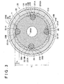
- FIG 3 is a sectional view taken along line B-B of FIG 1 .
- FIG. 4 is an exploded perspective view showing an input-side gear that is held in a carrier of the vehicle differential according to the first embodiment of the invention when viewed from one side.
- FIG. 5 is an exploded perspective view showing the input-side gear that is held in the carrier of the vehicle differential according to the first embodiment of the invention when viewed from the other side.
- FIG. 6 is a perspective view showing the carrier of the vehicle differential according to the first embodiment of the invention when viewed from one side.
- FIG. 7 is a perspective view showing the carrier of the vehicle differential according to the first embodiment of the invention when viewed from the other side.
- the vehicle differential indicated at reference numeral 1 in FIGS. 1 to 3 is, for example, used as a center differential of a four-wheel drive vehicle in which drive torque from a drive power source is distributed to the front wheel side and the rear wheel side.
- the vehicle differential includes: a planetary carrier 2A, serving as an input member, which rotates receiving the drive torque (engine torque) from the drive power source; a plurality of planetary gears 2B, 2B, ..., serving as the input-side gears, which receive the torque from the planetary carrier 2A; a sun gear 2C, serving as an output-side gear on one side, which meshes with the plurality of planetary gears 2B, 2B, ...; an internal gear 2D, serving as an output-side gear on the other side, which is disposed coaxially with the sun gear 2C and meshes with the plurality of planetary gears 2B, 2B, ...; and a differential case 2E that houses the internal gear 2D, the sun gear 2C, the planetary carrier 2
- the planetary carrier 2A has a carrier base portion 20A and a carrier brim portion 21A.
- the planetary carrier 2A is interposed between the sun gear 2C and the internal gear 2D, and is formed as a stepped cylindrical body in which the inner diameter and the outer diameter of the carrier base portion 20A differ from the inner diameter and the outer diameter of the carrier brim portion 21A, respectively.
- the planetary carrier 2A is designed to rotate about a rotation axis O.
- the planetary carrier 2A is provided with gear holding portions 22A that rotatably hold the planetary gears 2B, 2B, ...
- the gear holding portion 22A includes a first reception hole 220A and a second reception hole 221A and extends through the carrier base portion 20A and the carrier brim portion 21A.
- the first reception hole 220A is open inwardly in the radial direction of the planetary carrier 2A (at the inner circumferential surface of the carrier brim portion 21A) and open in the direction parallel to the rotation axis O (on both the sun gear side and the internal gear side), and is provided in the carrier brim portion 21A.
- the inner circumferential surface of the first reception hole 220A (torque transmitting surface) is formed by a first gear supporting surface 2200A, which is a curved surface that fits tooth tip surfaces of gear portions 20B, 20B, ... (described later) of the planetary gears 2B, 2B, ... More specifically, the first gear supporting surface 2200A is formed in a cylindrical shape that has a curvature slightly greater than the curvature of the tooth tip surfaces of the gear portions 20B, 20B, ...
- the second reception hole 221A is open outwardly in the radial direction of the planetary carrier 2A (at the outer circumferential surface of the carrier base portion 20A) and open in the direction parallel to the rotation axis O (on the sun gear side), is connected to the first reception hole 220A, and is provided in the carrier base portion 20A.
- the inner circumferential surface (torque transmitting surface) of the second reception hole 221A is formed by a second gear supporting surface 2210A, which is a curved surface that fits tooth tip surfaces of gear portions 21B, 21B, ... (described later) of the planetary gears 2B, 2B, ...
- the bottoms of the second reception holes 221A are formed by third gear supporting surfaces 2211A, which slidably support the axial end surfaces (free end surfaces) of the gear portions 21B, 21B, ... of the planetary gears 2B, 2B, ...
- the carrier base portion 20A is formed by a cylindrical body that has a hole open in the rotation axis direction of the planetary carrier 2A.
- the inner circumferential surface of the carrier base portion 20A is provided with a spline fitting portion 200A for connecting the carrier base portion 20A with an input shaft (not shown) so that the input shaft can move in the axial direction and cannot rotate relative to the carrier base portion 20A.
- the carrier brim portion 21A is integral with the carrier base portion 20A and formed by an annular body that has a hole open in the rotation axis direction of the planetary carrier 2A.
- the outer diameter of the carrier brim portion 21A is set greater than the outer diameter of the carrier base portion 20A, and the inner diameter of the carrier brim portion 21A is set greater than the inner diameter of the carrier base portion 20A.
- the planetary gears 2B, 2B, ... are helical gears, each having two large and small gear portions 20B and 21B, of which the pitch circle diameters D 1 and D 2 (D 1 >D 2 ) differ from each other (the direction of spiral is the same) (that is, the gear portion 20B has the gear dimension of the pitch circle diameter D 1 and the gear portion 21B has the gear dimension of the pitch circle diameter D 2 ), and each of the planetary gears 2B, 2B, ... is rotatably housed in the first reception hole 220A and the second reception hole 221A of the planetary carrier 2A.
- the gear portion 20B meshes with the sun gear 2C and is rotatably housed in the first reception hole 220A.
- the gear portion 20B is designed to transmit a torque exerted by the planetary carrier 2A to an output shaft on the left side in FIG. 1 (output shaft to be connected to the front axle) through the sun gear 2C.
- Annular thrust washers 5 and 6, positioned at the periphery of the sun gear 2C, are interposed between the axial tip end surface (free end surface) of the gear portion 20B and the bottom surface of the differential case 2E.
- the thrust washer 5 rotates with the planetary carrier 2A and the thrust washer 6 rotates with the differential case 2E.
- the gear portions 21B mesh with the internal gear 2D and are rotatably housed in the second reception holes 221A.
- the gear portion 21B is designed to transmit a torque exerted by the planetary carrier 2A to an output shaft on the right side (output shaft to be connected to the rear axle) through the internal gear 2D.
- the sun gear 2C meshes with the gear portions 20B, 20B, ... of the planetary gears 2B, 2B, ..., is rotatably placed coaxially with the internal gear 2D, and is housed in the carrier brim portion 21A of the planetary carrier 2A.
- the sun gear 2C is a cylindrical helical gear having the axis the same as the rotation axis O.
- the sun gear 2C is designed to receive a torque from the gear portions 20B, 20B, ... of the planetary gears 2B, 2B, ... and output the torque to the output shaft on the left side in FIG 1 .
- the inner circumferential surface of the sun gear 2C is provided with the spline fitting portion 20C for connecting the sun gear 2C with an output shaft on the left side so that the output shaft can move in the axial direction and cannot rotate relative to the sun gear 2C.
- the pitch circle diameter D 3 and the number of teeth Z 3 of the cylindrical helical gear of the sun gear 2C are set greater than the pitch circle diameter D 1 and the number of teeth Z 1 of the gear portions 20B, 20B, ... of the planetary gears 2B, 2B, ..., respectively.
- the internal gear 2D has a boss portion 20D and a gear portion 21D, meshes with the gear portions 21B, 21B, ... of the planetary gears 2B, 2B, ..., and is rotatably placed coaxially with the planetary carrier 2A.
- the internal gear 2D is a cylindrical helical gear having the axis the same as the rotation axis O.
- the internal gear 2D receives a torque from the gear portions 21B, 21B, ... of the planetary gears 2B, 2B, ..., and outputs the torque to the output shaft on the right side in FIG. 1 .
- the boss portion 20D is a cylindrical body an placed at the position opposed to the sun gear 2C with the planetary carrier 2A interposed therebetween.
- a brim portion 200D is provided on the outer circumferential surface of the boss portion 20D, the brim portion 200D having a flange end surface that faces the end surface opposite to the sun gear-side end surface of the planetary carrier 2A.
- the inner circumferential surface of the boss portion 20D is provided with a spline fitting portion 201D for connecting the boss portion 20D with the output shaft on the right side so that the output shaft can move in the axial direction and cannot rotate relative to the boss portion 20D.
- the gear portion 21D meshes with the gear portions 21B, 21B, ... of the planetary gears 2B, 2B, ..., is positioned around the periphery of the planetary carrier 2A, and is integrated with the boss portion 20D of the internal gear 2D with the brim portion 200D interposed therebetween.
- a brim portion 210D positioned on the sun gear side, is integrally provided on the outer circumferential surface of the gear portion 21D.
- the pitch circle diameter D 4 and the number of teeth Z 4 of the gear portion 21D are set grater than the pitch circle diameter D 3 and the number of teeth Z 3 of the sun gear 2C.
- the ratio between the torque transmitted to the internal gear 2D and the torque transmitted to the sun gear 2C is D 4 /D 2 :D 3 /D 1 , and this embodiment is configured so that the torque transmitted to the internal gear 2D is twice or more as high as the torque transmitted to the sun gear 2C.
- the differential case 2E includes: a cylindrical case body 20E, having a bottom portion, that is open in one direction along the rotation axis O; and a substantially annular ring bolt 21E that covers the opening of the case body 20E (a part inserting opening 2000E described later).
- An insertion hole through which an output shaft is inserted is formed in the bottom portion of the differential case 2E.
- the end portion of the sun gear 2C that is one of the axial end portions of the sun gear 2C on the side opposite to the planetary carrier side is welded to the inner edge of the insertion hole, so that the differential case 2E and the sun gear 2C are joined so as to rotate together.
- the differential case 2E is a stepped, hollow structure that houses the planetary carrier 2A (planetary gears 2B, 2B, ...) and part of the sun gear 2C and the internal gear 2D therein.
- the case body 20E is formed of a stepped cylindrical body, having a bottom portion, that includes three, differently-sized cylindrical portions 200E to 202E, of which the inner diameters differ from each other and of which the outer diameters differ from each other.
- the large-diameter cylindrical portion 200E has the part inserting opening 2000E on the ring bolt 21E side and is positioned on one side of the case body 20E with respect to the axial direction (on the ring bolt side).
- the small-diameter cylindrical portion 201E is positioned on the other side of the case body 20E with respect to the axial direction.
- the cylindrical portion 201E is provided with a bottom portion 2010E that is opposed to the axial tip end surfaces of the planetary gears 2B, 2B, ... (gear portions 20B, 20B, ...) with the thrust washers 5 and 6 interposed therebetween, and a gear insertion hole 2011E that passes through the bottom portion 2010E and into which the sun gear 2C is inserted.
- the middle-diameter cylindrical portion 202E is interposed between the cylindrical portion 200E and the cylindrical portion 201E and the dimensions of the cylindrical portion 202E are determined so that the inner diameter and the outer diameter of the cylindrical portion 202E gradually increase from the sun gear side to the internal gear side.
- the ring bolt 21B is screwed into the part inserting opening 2000E of the case body 20B (cylindrical portion 200E).
- the ring bolt 21E is designed to function as a movement restriction member that restricts the movement of the internal gear 2D in the direction opposite to the sun gear side along the rotation axis O.
- the planetary carrier 2A When the torque from the engine of the vehicle is input to the planetary carrier 2A, the planetary carrier 2A is driven to rotate about the rotation axis O. When the planetary carrier 2A is driven to rotate, the torque is transmitted to the planetary gears 2B, 2B, ..., and further transmitted from the gear portions 20B, 20B, ... of the planetary gears 2B, 2B, ... to the sun gear 2C, and at the same time transmitted from the gear portions 21B, 21B, ... of the planetary gears 2B, 2B, ... to the internal gear 2D.
- the torque from the engine is transmitted to the front and rear output shafts through the planetary carrier 2A and the planetary gears 2B, 2B, ..., and through the sun gear 2C and the internal gear 2D.
- the torque from the engine transmitted to the planetary carrier 2A causes the planetary carrier 2A to rotate about the rotation axis O and causes the planetary gears 2B, 2B, ... to revolve about the center axis of the sun gear 2C and the internal gear 2D without rotation about their own axes, so that the planetary gears 2B, 2B, ..., the sun gear 2C and the internal gear 2D rotate with the planetary carrier 2A.
- the torque from the engine is transmitted to the front and rear output shafts without any loss, immediately responding to the unbalance of the ground reaction forces within the range of the limited slip differential torque during static friction, so that the front and rear output shafts rotate at the same speed.
- the planetary gears 2B, 2B, ... rotate while meshing with the output gears 2C and 2D, so that the front-side output shaft rotates at a speed lower than the rotational speed of the planetary carrier 2A and the rear-side output shaft rotates at a speed higher than the rotational speed of the planetary carrier 2A.
- the torque from the engine is distributed to the front and rear output shafts in a predetermined uneven ratio such that a higher torque is transmitted to the axle on the front side on which the ground reaction force is higher, so that the loss of the total drive force on both the front and rear sides is reduced to secure running through performance.
- the limited slip differential torque is obtained by virtue of the frictional resistance between the tooth tip surfaces of the gear portions 20B, 20B, ... and the first gear supporting surfaces 2200A and the frictional resistance between the tooth tip surfaces of the gear portions 21B, 21B, ... and the second gear supporting surfaces 2210A.
- FIG. 8 is a sectional view for explaining a vehicle differential according to a second embodiment of the invention.
- FIG. 9 is a sectional view showing a state in which a planetary carrier and a thrust washer of the vehicle differential according to the second embodiment of the invention mesh with each other.
- the planetary gear 2G in the vehicle differential 81 of the second embodiment has a large-diameter gear portion 20G corresponding to the gear portion 20B of the first embodiment and a small-diameter gear portion 21G corresponding to the gear portion 21B of the first embodiment, and the large-diameter gear portion 20G and the small-diameter gear portion 21G are integrally connected by an intermediate portion 22G.
- the planetary carrier 2F has a carrier brim portion 21F corresponding to the carrier brim portion 21A of the first embodiment, and a first gear supporting surface 2200F corresponding to the first gear supporting surface 2200A of the first embodiment rubs against the tooth tip surfaces of the large-diameter gear portion 20G of the planetary gear 2G.
- the planetary carrier 2F has a second gear supporting surface 2210F corresponding to the second gear supporting surface 2210A of the first embodiment, and the second gear supporting surface 2210F rubs against the tooth tip surfaces of the small-diameter gear portion 21G of the planetary gear 2G.
- a second reception hole 221F of the planetary carrier 2F that receives the small-diameter gear portion 21G of the planetary gear 2G is open in the axial direction on the side facing the brim portion 200D, and the axial end surface of the small-diameter portion 21G of the planetary gear 2G faces the brim portion 200D of the internal gear 2D.
- the planetary carrier 2F is not provided with the portion corresponding to the third gear supporting surface 2211A of the first embodiment.
- a wall portion 210F that radially inwardly protrudes from an axial end portion of the first gear supporting surface 2200F is formed between the first reception hole 220F and the second reception hole 221F of the planetary carrier 2F.
- the wall portion 210F is formed to have dimensions such that the small-diameter gear portion 21G of the planetary gear 2G supported by the gear holding portion 22F can be inserted in the axial direction and the large-diameter gear portion 20G cannot be inserted in the axial direction.
- the wall portion 210F forms a bottom portion (fourth gear supporting surface) 2201F of the first reception hole 220F and the movement of the planetary gear 2G in the direction from the gear portion 20G side toward the gear portion 21G side (direction toward the right side in FIG 8 ) is restricted by the contact of the end surface of the gear portion 20G on the intermediate portion (stepped portion) 22G side with the wall portion 210F.
- the axial end surface of the small-diameter gear portion 21G is not brought into contact with the brim portion 200D of the internal gear 2D.
- a cylindrical portion 211D that extends from near the periphery of the brim portion 200D in the axial direction is formed on the internal gear 2D.
- the outer diameter of the cylindrical portion 211D is smaller than the outer diameter of the brim portion 200D and an annular protruding portion 212D corresponding to the difference between the outer diameter of the cylindrical portion 211D and the outer diameter of the brim portion 200D is formed on the outer side of the cylindrical portion 211D when the internal gear 2D is viewed from the left in FIG 8 .
- a concave portion 1201E into which the annular protruding portion 212D is fitted is formed in the differential case 2E and the ring bolt 21E is screwed into the differential case 2E with the annular protruding portion 212D fitted into the concave portion 1201E, so that the internal gear 2D and the differential case 2E are joined so that the internal gear 2D and the differential case 2E cannot rotate relative to each other.
- An annular gear portion 23 is placed on the inner side of the cylindrical portion 211D and is spline fitted into the cylindrical portion 211D so that the gear portion 23 cannot rotate relative to the cylindrical portion 211D.
- a helical gear that meshes with the small-diameter gear portion 21G of the planetary gear 2G is formed on the inner circumferential surface of the gear portion 23.
- the thrust washers 5 and 6 are interposed between one end surface of the planetary carrier 2F and the bottom portion of the differential case 2E. As shown in FIG. 9 , a protrusion 5A is formed on the periphery of the thrust washer 5 and the protrusion 5A is fitted into a concave portion 201F provided in an end surface of the planetary carrier 2F, so that the planetary carrier 2F and the thrust washer 5 are prevented from rotating relative to each other. In a similar manner, the thrust washer 6 is placed on the bottom portion of the differential case 2E so that the thrust washer 6 and the differential case 2E cannot rotate relative to each other.
- Thrust washers 71 and 81 are disposed between the sun gear 2C and a carrier base portion 20F of the planetary carrier 2F. Thrust washers 70 and 80 are disposed between the sun gear 2C and the bottom portion of the differential case 2E. The thrust washer 81 cannot rotate relative to the planetary carrier 2F and the thrust washer 80 cannot rotate relative to the differential case 2E. The thrust washers 70 and 71 cannot rotate relative to the sun gear 2C. Thus, when the planetary carrier 2F and the sun gear 2C rotate relative to each other, the thrust washers 81 and 71 rub against each other and when the differential case 2E and the sun gear 2C rotate relative to each other, the thrust washers 80 and 70 rub against each other.
- the gear portion 23 is provided separately from the cylindrical portion 211D, so that it is facilitated to form the gear teeth of the internal gear 2D, and it is made possible to form gear teeth to the end portion that abuts the brim portion 200D.
- the clearance for tools that was required when the gear teeth were machined becomes unnecessary, so that it is possible to reduce the axial length of the internal gear 2D.
- the pitch circle diameters of the gears may be set to the dimensions such that the pitch circle diameters of the input side gears (gear portions 20B, 20B, ... and gear portions 21B, 21B, ... of the planetary gears 2B, 2B, ...) and the pitch circle diameters of the output side gears (sun gear 2C and internal gear 2D) satisfy the relation, D 3 /D 1 >D 4 /D 2 .
- the torque transmitted through the internal gear is lower than the torque transmitted through the sun gear.
- the gear holding portion (22A) has a first gear supporting surface (2200A) that slidably supports tooth tip surfaces of the gear portion (20B), of which the pitch circle diameter is larger, on a portion except on the radially inner side with respect to the carrier (2A), and a second gear supporting surface (2210A) that slidably supports tooth tip surfaces of the gear portion (21B), of which the pitch circle diameter is smaller, on a portion except on the radially outer side with respect to the carrier (2A).
Landscapes
- Engineering & Computer Science (AREA)
- General Engineering & Computer Science (AREA)
- Mechanical Engineering (AREA)
- Retarders (AREA)
Applications Claiming Priority (1)
| Application Number | Priority Date | Filing Date | Title |
|---|---|---|---|
| JP2008135706A JP5125761B2 (ja) | 2008-05-23 | 2008-05-23 | プラネタリキャリア、遊星歯車機構、及びこれらを備えた車両用差動装置 |
Publications (3)
| Publication Number | Publication Date |
|---|---|
| EP2123943A2 true EP2123943A2 (fr) | 2009-11-25 |
| EP2123943A3 EP2123943A3 (fr) | 2011-05-04 |
| EP2123943B1 EP2123943B1 (fr) | 2013-05-01 |
Family
ID=40823429
Family Applications (1)
| Application Number | Title | Priority Date | Filing Date |
|---|---|---|---|
| EP09160917.2A Active EP2123943B1 (fr) | 2008-05-23 | 2009-05-22 | Porte-satellites, mécanisme d'engrenage de type planétaire et différentiel de véhicule doté de ceux-ci |
Country Status (3)
| Country | Link |
|---|---|
| US (1) | US8182387B2 (fr) |
| EP (1) | EP2123943B1 (fr) |
| JP (1) | JP5125761B2 (fr) |
Cited By (2)
| Publication number | Priority date | Publication date | Assignee | Title |
|---|---|---|---|---|
| CN105705838A (zh) * | 2013-11-25 | 2016-06-22 | 爱信艾达株式会社 | 行星架 |
| CN109153326A (zh) * | 2016-04-05 | 2019-01-04 | 沃尔沃建筑设备公司 | 行星架和行星齿轮变速器 |
Families Citing this family (6)
| Publication number | Priority date | Publication date | Assignee | Title |
|---|---|---|---|---|
| WO2013036483A1 (fr) * | 2011-09-06 | 2013-03-14 | Eaton Corporation | Agencement d'ensemble de train planétaire différentiel compact |
| JP5709112B2 (ja) * | 2013-09-17 | 2015-04-30 | 英和 当 | 遊星歯車機構及びその動力伝達部材 |
| US9638310B2 (en) | 2015-06-29 | 2017-05-02 | Deere & Company | Drive assembly with a rotating housing attached to an output interface |
| US9562603B2 (en) * | 2015-06-29 | 2017-02-07 | Deere & Company | Drive assembly with a rotating housing attached to an output interface |
| JP6891659B2 (ja) * | 2017-06-21 | 2021-06-18 | 株式会社ジェイテクト | 差動装置 |
| US10781911B2 (en) | 2018-09-13 | 2020-09-22 | Cnh Industrial America Llc | Planetary gear assembly |
Citations (1)
| Publication number | Priority date | Publication date | Assignee | Title |
|---|---|---|---|---|
| JP2003314663A (ja) | 2002-04-22 | 2003-11-06 | Bosch Automotive Systems Corp | 車両用差動歯車装置 |
Family Cites Families (6)
| Publication number | Priority date | Publication date | Assignee | Title |
|---|---|---|---|---|
| US1730270A (en) * | 1929-02-11 | 1929-10-01 | Friedell Philip Adelbert | Speed-reducing transmission |
| US3792628A (en) * | 1972-07-03 | 1974-02-19 | Mack Trucks | Torque proportioning and spin limiting differential |
| DE19506068C1 (de) * | 1995-02-22 | 1996-04-11 | Gkn Viscodrive Gmbh | Differentialgetriebe mit Sperrwirkung |
| JP2003314664A (ja) * | 2002-04-24 | 2003-11-06 | Bosch Automotive Systems Corp | 車両用差動歯車装置 |
| JP3944041B2 (ja) * | 2002-09-19 | 2007-07-11 | 株式会社ジェイテクト | 遊星歯車装置 |
| WO2007071115A1 (fr) * | 2005-12-23 | 2007-06-28 | Xiaochun Wang | Differentiel interponts a glissement limite a couple divise |
-
2008
- 2008-05-23 JP JP2008135706A patent/JP5125761B2/ja active Active
-
2009
- 2009-05-22 EP EP09160917.2A patent/EP2123943B1/fr active Active
- 2009-05-22 US US12/470,678 patent/US8182387B2/en active Active
Patent Citations (1)
| Publication number | Priority date | Publication date | Assignee | Title |
|---|---|---|---|---|
| JP2003314663A (ja) | 2002-04-22 | 2003-11-06 | Bosch Automotive Systems Corp | 車両用差動歯車装置 |
Cited By (5)
| Publication number | Priority date | Publication date | Assignee | Title |
|---|---|---|---|---|
| CN105705838A (zh) * | 2013-11-25 | 2016-06-22 | 爱信艾达株式会社 | 行星架 |
| CN105705838B (zh) * | 2013-11-25 | 2018-03-06 | 爱信艾达株式会社 | 行星架 |
| CN109153326A (zh) * | 2016-04-05 | 2019-01-04 | 沃尔沃建筑设备公司 | 行星架和行星齿轮变速器 |
| EP3439907A4 (fr) * | 2016-04-05 | 2019-09-11 | Volvo Construction Equipment AB | Porte-satellites et transmission à engrenages planétaires |
| US10857877B2 (en) | 2016-04-05 | 2020-12-08 | Volvo Construction Equipment Ab | Planet carrier and a planetary gear transmission |
Also Published As
| Publication number | Publication date |
|---|---|
| JP2009281544A (ja) | 2009-12-03 |
| US8182387B2 (en) | 2012-05-22 |
| EP2123943A3 (fr) | 2011-05-04 |
| EP2123943B1 (fr) | 2013-05-01 |
| JP5125761B2 (ja) | 2013-01-23 |
| US20090291798A1 (en) | 2009-11-26 |
Similar Documents
| Publication | Publication Date | Title |
|---|---|---|
| EP2123943B1 (fr) | Porte-satellites, mécanisme d'engrenage de type planétaire et différentiel de véhicule doté de ceux-ci | |
| KR101574008B1 (ko) | 포개진 링 기어를 갖춘 유성 기어세트를 갖는 구동 모듈 | |
| JP5067192B2 (ja) | 車両用差動装置 | |
| CA2718682C (fr) | Demultiplicateur planetaire | |
| US8216105B2 (en) | Differential apparatus for vehicle and assembling method thereof | |
| JP2018128078A (ja) | 伝動装置 | |
| EP2050985B1 (fr) | Rapport de vitesse différentiel | |
| KR20220151438A (ko) | 인휠 구동장치 및 인휠 구동장치의 조립방법 | |
| JPH10311403A (ja) | デファレンシャル装置 | |
| JP6487664B2 (ja) | 差動装置 | |
| JP4770788B2 (ja) | 車両用差動歯車装置 | |
| JP4686982B2 (ja) | 差動装置 | |
| WO2005115791A1 (fr) | Dispositif differentiel a glissement limite convenant pour une miniaturisation | |
| EP1491796B1 (fr) | Differentiel pour véhicule | |
| JP5713631B2 (ja) | デファレンシャル装置 | |
| JP4910799B2 (ja) | 混成差動歯車装置 | |
| US20200173530A1 (en) | Vehicle differential device | |
| EP2233790B1 (fr) | Unité différentielle de véhicule | |
| US9593741B2 (en) | Transmission with torsional damper | |
| JP2019074210A (ja) | ドライブモジュール | |
| US6729991B1 (en) | Combined differential gear device | |
| JP2010144855A (ja) | ドライブピニオン | |
| JP2020133820A (ja) | トルクコンバータ | |
| JP4891644B2 (ja) | 車両の左右駆動力配分装置 | |
| JP3967575B2 (ja) | デファレンシャル装置 |
Legal Events
| Date | Code | Title | Description |
|---|---|---|---|
| PUAI | Public reference made under article 153(3) epc to a published international application that has entered the european phase |
Free format text: ORIGINAL CODE: 0009012 |
|
| AK | Designated contracting states |
Kind code of ref document: A2 Designated state(s): AT BE BG CH CY CZ DE DK EE ES FI FR GB GR HR HU IE IS IT LI LT LU LV MC MK MT NL NO PL PT RO SE SI SK TR |
|
| PUAL | Search report despatched |
Free format text: ORIGINAL CODE: 0009013 |
|
| AK | Designated contracting states |
Kind code of ref document: A3 Designated state(s): AT BE BG CH CY CZ DE DK EE ES FI FR GB GR HR HU IE IS IT LI LT LU LV MC MK MT NL NO PL PT RO SE SI SK TR |
|
| AX | Request for extension of the european patent |
Extension state: AL BA RS |
|
| 17P | Request for examination filed |
Effective date: 20111017 |
|
| 17Q | First examination report despatched |
Effective date: 20111207 |
|
| GRAP | Despatch of communication of intention to grant a patent |
Free format text: ORIGINAL CODE: EPIDOSNIGR1 |
|
| RIN1 | Information on inventor provided before grant (corrected) |
Inventor name: FUJII, NORIYUKI C/O JTEKT CORPORATION Inventor name: NISHIJI, MAKOTO C/O JTEKT CORPORATION |
|
| GRAS | Grant fee paid |
Free format text: ORIGINAL CODE: EPIDOSNIGR3 |
|
| GRAA | (expected) grant |
Free format text: ORIGINAL CODE: 0009210 |
|
| AK | Designated contracting states |
Kind code of ref document: B1 Designated state(s): AT BE BG CH CY CZ DE DK EE ES FI FR GB GR HR HU IE IS IT LI LT LU LV MC MK MT NL NO PL PT RO SE SI SK TR |
|
| REG | Reference to a national code |
Ref country code: GB Ref legal event code: FG4D |
|
| REG | Reference to a national code |
Ref country code: CH Ref legal event code: EP Ref country code: AT Ref legal event code: REF Ref document number: 610148 Country of ref document: AT Kind code of ref document: T Effective date: 20130515 |
|
| REG | Reference to a national code |
Ref country code: IE Ref legal event code: FG4D |
|
| REG | Reference to a national code |
Ref country code: DE Ref legal event code: R096 Ref document number: 602009015364 Country of ref document: DE Effective date: 20130627 |
|
| REG | Reference to a national code |
Ref country code: AT Ref legal event code: MK05 Ref document number: 610148 Country of ref document: AT Kind code of ref document: T Effective date: 20130501 |
|
| REG | Reference to a national code |
Ref country code: NL Ref legal event code: VDEP Effective date: 20130501 |
|
| REG | Reference to a national code |
Ref country code: LT Ref legal event code: MG4D |
|
| PG25 | Lapsed in a contracting state [announced via postgrant information from national office to epo] |
Ref country code: IS Free format text: LAPSE BECAUSE OF FAILURE TO SUBMIT A TRANSLATION OF THE DESCRIPTION OR TO PAY THE FEE WITHIN THE PRESCRIBED TIME-LIMIT Effective date: 20130901 Ref country code: FI Free format text: LAPSE BECAUSE OF FAILURE TO SUBMIT A TRANSLATION OF THE DESCRIPTION OR TO PAY THE FEE WITHIN THE PRESCRIBED TIME-LIMIT Effective date: 20130501 Ref country code: LT Free format text: LAPSE BECAUSE OF FAILURE TO SUBMIT A TRANSLATION OF THE DESCRIPTION OR TO PAY THE FEE WITHIN THE PRESCRIBED TIME-LIMIT Effective date: 20130501 Ref country code: SI Free format text: LAPSE BECAUSE OF FAILURE TO SUBMIT A TRANSLATION OF THE DESCRIPTION OR TO PAY THE FEE WITHIN THE PRESCRIBED TIME-LIMIT Effective date: 20130501 Ref country code: SE Free format text: LAPSE BECAUSE OF FAILURE TO SUBMIT A TRANSLATION OF THE DESCRIPTION OR TO PAY THE FEE WITHIN THE PRESCRIBED TIME-LIMIT Effective date: 20130501 Ref country code: ES Free format text: LAPSE BECAUSE OF FAILURE TO SUBMIT A TRANSLATION OF THE DESCRIPTION OR TO PAY THE FEE WITHIN THE PRESCRIBED TIME-LIMIT Effective date: 20130812 Ref country code: AT Free format text: LAPSE BECAUSE OF FAILURE TO SUBMIT A TRANSLATION OF THE DESCRIPTION OR TO PAY THE FEE WITHIN THE PRESCRIBED TIME-LIMIT Effective date: 20130501 Ref country code: GR Free format text: LAPSE BECAUSE OF FAILURE TO SUBMIT A TRANSLATION OF THE DESCRIPTION OR TO PAY THE FEE WITHIN THE PRESCRIBED TIME-LIMIT Effective date: 20130802 Ref country code: PT Free format text: LAPSE BECAUSE OF FAILURE TO SUBMIT A TRANSLATION OF THE DESCRIPTION OR TO PAY THE FEE WITHIN THE PRESCRIBED TIME-LIMIT Effective date: 20130902 Ref country code: NO Free format text: LAPSE BECAUSE OF FAILURE TO SUBMIT A TRANSLATION OF THE DESCRIPTION OR TO PAY THE FEE WITHIN THE PRESCRIBED TIME-LIMIT Effective date: 20130801 |
|
| PG25 | Lapsed in a contracting state [announced via postgrant information from national office to epo] |
Ref country code: BG Free format text: LAPSE BECAUSE OF FAILURE TO SUBMIT A TRANSLATION OF THE DESCRIPTION OR TO PAY THE FEE WITHIN THE PRESCRIBED TIME-LIMIT Effective date: 20130801 Ref country code: HR Free format text: LAPSE BECAUSE OF FAILURE TO SUBMIT A TRANSLATION OF THE DESCRIPTION OR TO PAY THE FEE WITHIN THE PRESCRIBED TIME-LIMIT Effective date: 20130501 Ref country code: CY Free format text: LAPSE BECAUSE OF FAILURE TO SUBMIT A TRANSLATION OF THE DESCRIPTION OR TO PAY THE FEE WITHIN THE PRESCRIBED TIME-LIMIT Effective date: 20130501 Ref country code: PL Free format text: LAPSE BECAUSE OF FAILURE TO SUBMIT A TRANSLATION OF THE DESCRIPTION OR TO PAY THE FEE WITHIN THE PRESCRIBED TIME-LIMIT Effective date: 20130501 |
|
| PG25 | Lapsed in a contracting state [announced via postgrant information from national office to epo] |
Ref country code: LV Free format text: LAPSE BECAUSE OF FAILURE TO SUBMIT A TRANSLATION OF THE DESCRIPTION OR TO PAY THE FEE WITHIN THE PRESCRIBED TIME-LIMIT Effective date: 20130501 |
|
| REG | Reference to a national code |
Ref country code: CH Ref legal event code: PL |
|
| PG25 | Lapsed in a contracting state [announced via postgrant information from national office to epo] |
Ref country code: SK Free format text: LAPSE BECAUSE OF FAILURE TO SUBMIT A TRANSLATION OF THE DESCRIPTION OR TO PAY THE FEE WITHIN THE PRESCRIBED TIME-LIMIT Effective date: 20130501 Ref country code: LI Free format text: LAPSE BECAUSE OF NON-PAYMENT OF DUE FEES Effective date: 20130531 Ref country code: MC Free format text: LAPSE BECAUSE OF FAILURE TO SUBMIT A TRANSLATION OF THE DESCRIPTION OR TO PAY THE FEE WITHIN THE PRESCRIBED TIME-LIMIT Effective date: 20130501 Ref country code: EE Free format text: LAPSE BECAUSE OF FAILURE TO SUBMIT A TRANSLATION OF THE DESCRIPTION OR TO PAY THE FEE WITHIN THE PRESCRIBED TIME-LIMIT Effective date: 20130501 Ref country code: CH Free format text: LAPSE BECAUSE OF NON-PAYMENT OF DUE FEES Effective date: 20130531 Ref country code: BE Free format text: LAPSE BECAUSE OF FAILURE TO SUBMIT A TRANSLATION OF THE DESCRIPTION OR TO PAY THE FEE WITHIN THE PRESCRIBED TIME-LIMIT Effective date: 20130501 Ref country code: DK Free format text: LAPSE BECAUSE OF FAILURE TO SUBMIT A TRANSLATION OF THE DESCRIPTION OR TO PAY THE FEE WITHIN THE PRESCRIBED TIME-LIMIT Effective date: 20130501 Ref country code: CZ Free format text: LAPSE BECAUSE OF FAILURE TO SUBMIT A TRANSLATION OF THE DESCRIPTION OR TO PAY THE FEE WITHIN THE PRESCRIBED TIME-LIMIT Effective date: 20130501 |
|
| REG | Reference to a national code |
Ref country code: IE Ref legal event code: MM4A |
|
| PG25 | Lapsed in a contracting state [announced via postgrant information from national office to epo] |
Ref country code: IT Free format text: LAPSE BECAUSE OF FAILURE TO SUBMIT A TRANSLATION OF THE DESCRIPTION OR TO PAY THE FEE WITHIN THE PRESCRIBED TIME-LIMIT Effective date: 20130501 Ref country code: NL Free format text: LAPSE BECAUSE OF FAILURE TO SUBMIT A TRANSLATION OF THE DESCRIPTION OR TO PAY THE FEE WITHIN THE PRESCRIBED TIME-LIMIT Effective date: 20130501 Ref country code: RO Free format text: LAPSE BECAUSE OF FAILURE TO SUBMIT A TRANSLATION OF THE DESCRIPTION OR TO PAY THE FEE WITHIN THE PRESCRIBED TIME-LIMIT Effective date: 20130501 |
|
| PLBE | No opposition filed within time limit |
Free format text: ORIGINAL CODE: 0009261 |
|
| REG | Reference to a national code |
Ref country code: FR Ref legal event code: ST Effective date: 20140131 |
|
| STAA | Information on the status of an ep patent application or granted ep patent |
Free format text: STATUS: NO OPPOSITION FILED WITHIN TIME LIMIT |
|
| 26N | No opposition filed |
Effective date: 20140204 |
|
| GBPC | Gb: european patent ceased through non-payment of renewal fee |
Effective date: 20130801 |
|
| PG25 | Lapsed in a contracting state [announced via postgrant information from national office to epo] |
Ref country code: IE Free format text: LAPSE BECAUSE OF NON-PAYMENT OF DUE FEES Effective date: 20130522 |
|
| REG | Reference to a national code |
Ref country code: DE Ref legal event code: R097 Ref document number: 602009015364 Country of ref document: DE Effective date: 20140204 |
|
| PG25 | Lapsed in a contracting state [announced via postgrant information from national office to epo] |
Ref country code: FR Free format text: LAPSE BECAUSE OF NON-PAYMENT OF DUE FEES Effective date: 20130701 |
|
| PG25 | Lapsed in a contracting state [announced via postgrant information from national office to epo] |
Ref country code: GB Free format text: LAPSE BECAUSE OF NON-PAYMENT OF DUE FEES Effective date: 20130801 |
|
| PG25 | Lapsed in a contracting state [announced via postgrant information from national office to epo] |
Ref country code: MT Free format text: LAPSE BECAUSE OF FAILURE TO SUBMIT A TRANSLATION OF THE DESCRIPTION OR TO PAY THE FEE WITHIN THE PRESCRIBED TIME-LIMIT Effective date: 20130501 |
|
| PG25 | Lapsed in a contracting state [announced via postgrant information from national office to epo] |
Ref country code: TR Free format text: LAPSE BECAUSE OF FAILURE TO SUBMIT A TRANSLATION OF THE DESCRIPTION OR TO PAY THE FEE WITHIN THE PRESCRIBED TIME-LIMIT Effective date: 20130501 |
|
| PG25 | Lapsed in a contracting state [announced via postgrant information from national office to epo] |
Ref country code: HU Free format text: LAPSE BECAUSE OF FAILURE TO SUBMIT A TRANSLATION OF THE DESCRIPTION OR TO PAY THE FEE WITHIN THE PRESCRIBED TIME-LIMIT; INVALID AB INITIO Effective date: 20090522 Ref country code: MK Free format text: LAPSE BECAUSE OF FAILURE TO SUBMIT A TRANSLATION OF THE DESCRIPTION OR TO PAY THE FEE WITHIN THE PRESCRIBED TIME-LIMIT Effective date: 20130501 Ref country code: LU Free format text: LAPSE BECAUSE OF NON-PAYMENT OF DUE FEES Effective date: 20130522 |
|
| PGFP | Annual fee paid to national office [announced via postgrant information from national office to epo] |
Ref country code: DE Payment date: 20230331 Year of fee payment: 15 |