EP2123574A1 - Filznadelverpackung - Google Patents
Filznadelverpackung Download PDFInfo
- Publication number
- EP2123574A1 EP2123574A1 EP08156671A EP08156671A EP2123574A1 EP 2123574 A1 EP2123574 A1 EP 2123574A1 EP 08156671 A EP08156671 A EP 08156671A EP 08156671 A EP08156671 A EP 08156671A EP 2123574 A1 EP2123574 A1 EP 2123574A1
- Authority
- EP
- European Patent Office
- Prior art keywords
- package according
- felting needle
- needle package
- container
- felting
- Prior art date
- Legal status (The legal status is an assumption and is not a legal conclusion. Google has not performed a legal analysis and makes no representation as to the accuracy of the status listed.)
- Granted
Links
Images


Classifications
-
- B—PERFORMING OPERATIONS; TRANSPORTING
- B65—CONVEYING; PACKING; STORING; HANDLING THIN OR FILAMENTARY MATERIAL
- B65D—CONTAINERS FOR STORAGE OR TRANSPORT OF ARTICLES OR MATERIALS, e.g. BAGS, BARRELS, BOTTLES, BOXES, CANS, CARTONS, CRATES, DRUMS, JARS, TANKS, HOPPERS, FORWARDING CONTAINERS; ACCESSORIES, CLOSURES, OR FITTINGS THEREFOR; PACKAGING ELEMENTS; PACKAGES
- B65D85/00—Containers, packaging elements or packages, specially adapted for particular articles or materials
- B65D85/20—Containers, packaging elements or packages, specially adapted for particular articles or materials for incompressible or rigid rod-shaped or tubular articles
- B65D85/24—Containers, packaging elements or packages, specially adapted for particular articles or materials for incompressible or rigid rod-shaped or tubular articles for needles, nails or like elongate small articles
-
- B—PERFORMING OPERATIONS; TRANSPORTING
- B65—CONVEYING; PACKING; STORING; HANDLING THIN OR FILAMENTARY MATERIAL
- B65D—CONTAINERS FOR STORAGE OR TRANSPORT OF ARTICLES OR MATERIALS, e.g. BAGS, BARRELS, BOTTLES, BOXES, CANS, CARTONS, CRATES, DRUMS, JARS, TANKS, HOPPERS, FORWARDING CONTAINERS; ACCESSORIES, CLOSURES, OR FITTINGS THEREFOR; PACKAGING ELEMENTS; PACKAGES
- B65D25/00—Details of other kinds or types of rigid or semi-rigid containers
- B65D25/02—Internal fittings
- B65D25/04—Partitions
-
- B—PERFORMING OPERATIONS; TRANSPORTING
- B65—CONVEYING; PACKING; STORING; HANDLING THIN OR FILAMENTARY MATERIAL
- B65D—CONTAINERS FOR STORAGE OR TRANSPORT OF ARTICLES OR MATERIALS, e.g. BAGS, BARRELS, BOTTLES, BOXES, CANS, CARTONS, CRATES, DRUMS, JARS, TANKS, HOPPERS, FORWARDING CONTAINERS; ACCESSORIES, CLOSURES, OR FITTINGS THEREFOR; PACKAGING ELEMENTS; PACKAGES
- B65D43/00—Lids or covers for rigid or semi-rigid containers
- B65D43/02—Removable lids or covers
-
- D—TEXTILES; PAPER
- D04—BRAIDING; LACE-MAKING; KNITTING; TRIMMINGS; NON-WOVEN FABRICS
- D04H—MAKING TEXTILE FABRICS, e.g. FROM FIBRES OR FILAMENTARY MATERIAL; FABRICS MADE BY SUCH PROCESSES OR APPARATUS, e.g. FELTS, NON-WOVEN FABRICS; COTTON-WOOL; WADDING ; NON-WOVEN FABRICS FROM STAPLE FIBRES, FILAMENTS OR YARNS, BONDED WITH AT LEAST ONE WEB-LIKE MATERIAL DURING THEIR CONSOLIDATION
- D04H18/00—Needling machines
- D04H18/02—Needling machines with needles
-
- B—PERFORMING OPERATIONS; TRANSPORTING
- B65—CONVEYING; PACKING; STORING; HANDLING THIN OR FILAMENTARY MATERIAL
- B65D—CONTAINERS FOR STORAGE OR TRANSPORT OF ARTICLES OR MATERIALS, e.g. BAGS, BARRELS, BOTTLES, BOXES, CANS, CARTONS, CRATES, DRUMS, JARS, TANKS, HOPPERS, FORWARDING CONTAINERS; ACCESSORIES, CLOSURES, OR FITTINGS THEREFOR; PACKAGING ELEMENTS; PACKAGES
- B65D25/00—Details of other kinds or types of rigid or semi-rigid containers
- B65D25/02—Internal fittings
- B65D25/10—Devices to locate articles in containers
- B65D25/101—Springs, elastic lips, or other resilient elements to locate the articles by pressure
-
- B—PERFORMING OPERATIONS; TRANSPORTING
- B65—CONVEYING; PACKING; STORING; HANDLING THIN OR FILAMENTARY MATERIAL
- B65D—CONTAINERS FOR STORAGE OR TRANSPORT OF ARTICLES OR MATERIALS, e.g. BAGS, BARRELS, BOTTLES, BOXES, CANS, CARTONS, CRATES, DRUMS, JARS, TANKS, HOPPERS, FORWARDING CONTAINERS; ACCESSORIES, CLOSURES, OR FITTINGS THEREFOR; PACKAGING ELEMENTS; PACKAGES
- B65D81/00—Containers, packaging elements, or packages, for contents presenting particular transport or storage problems, or adapted to be used for non-packaging purposes after removal of contents
- B65D81/24—Adaptations for preventing deterioration or decay of contents; Applications to the container or packaging material of food preservatives, fungicides, pesticides or animal repellants
- B65D81/26—Adaptations for preventing deterioration or decay of contents; Applications to the container or packaging material of food preservatives, fungicides, pesticides or animal repellants with provision for draining away, or absorbing, or removing by ventilation, fluids, e.g. exuded by contents; Applications of corrosion inhibitors or desiccators
- B65D81/266—Adaptations for preventing deterioration or decay of contents; Applications to the container or packaging material of food preservatives, fungicides, pesticides or animal repellants with provision for draining away, or absorbing, or removing by ventilation, fluids, e.g. exuded by contents; Applications of corrosion inhibitors or desiccators for absorbing gases, e.g. oxygen absorbers or desiccants
- B65D81/268—Adaptations for preventing deterioration or decay of contents; Applications to the container or packaging material of food preservatives, fungicides, pesticides or animal repellants with provision for draining away, or absorbing, or removing by ventilation, fluids, e.g. exuded by contents; Applications of corrosion inhibitors or desiccators for absorbing gases, e.g. oxygen absorbers or desiccants the absorber being enclosed in a small pack, e.g. bag, included in the package
Definitions
- the invention relates to a felted needle package.
- Felting needles are needed by felt manufacturers in very large numbers. They are wearing parts that are bought and kept in stock and used when needed.
- the needle manufacturer has the problem of packing felt needles in a rational way in such a way that they can not be damaged in the packaging even during rough handling and can be stored permanently. But they should also be packed so that the removal of the felting needles from the packaging by the needle user is easily possible. Danger of injury should be minimized.
- the felting needles have an elongated working part and an extension part of the same having an angled foot extending.
- the working parts usually have a smaller diameter than the holding parts. If the felting needles are arranged side by side and oriented in parallel, as well as compressed, a wedge-shaped bundle results.
- the DE 10 2005 036 329 A1 wedge-shaped needle packs of which the felting needle is picked up become.
- the wedge-shaped packaging can be inserted into a rectangular outer packaging.
- said document also proposes to arrange two wedge-shaped packages in the interior of the outer packaging oriented in opposite directions in order to make better use of the interior.
- the remaining cavities of the outer packaging are filled with foam bodies or the like.
- the felting needles are preferably oriented in the same direction in the respective partitioned section of the inner space.
- the working parts of the needles of the department concerned point in a first direction.
- the holding parts point in a second opposite direction.
- the needles of the needle bundle of the other divided from the partition receiving area are preferably oriented in the opposite direction.
- the partition is provided with at least one recess, which is arranged centrally, for example, and can pass from its upper edge to the ground.
- This or a smaller recess facilitates the removal of the felting needles from the packaging and encourages the operator to take the needles in the middle. This reduces the risk of injury from contact with the often very sharp or sharp-edged working parts, since these working parts are arranged in the end of the needles.
- an additional part for example in the form of an elbow, may be inserted into the container to shorten the receiving space at its respective tip.
- This measure can be used, for example, to adapt to shorter needles.
- the partition wall is preferably connected at least to the side wall and / or the bottom, more preferably to both the side wall and the bottom, resulting in a stable position of the partition wall in the container. In individual cases, it may also be appropriate to connect the partition only with the ground or only with the side wall in order to achieve flexibility in one or the other bending direction.
- the partition wall and / or the angle piece can be integrally, seamlessly connected to a container, its bottom and / or at least one wall.
- the container is then formed from one part.
- the container and its lid are made of the same plastic.
- the partition is preferably formed of the same plastic and, for example, integrally and seamlessly connected to the rest of the container.
- the above-mentioned angle or other insert preferably also consists of the same plastic. This measure is contrary to recycling.
- the container and its lid are made of a readily recyclable plastic, such as polystyrene or ABS.
- the lid is preferably designed as a multi-functional lid. It can attach to the container at an angle joint where the container and lid engage one another along the container rim. To improve the seal can be a soft seal in the lid or in the upper Be integrated edge of the container. A separate, the container outside comprehensive adhesive tape can then be omitted.
- the lid can be latched to the edge of the container.
- locking means or clips can be provided, which can be opened only by destruction.
- the clip then serves as a tamper-evident closure.
- the depot is a rust inhibitor in a form suitable for automation. It can be provided, for example, in the form of tablets, in the form of a gel, in the form of small powder bags, soaked paper, pieces of cardboard or fleece, etc.
- the depot with the said parts of the lid or the container is only adhesively bonded, if necessary, to be removed before recycling can.
- the container has a cuboid shape on the outside, its interior is divided into wedge-shaped chambers.
- the number of chambers is two or more.
- the floor plan of the chamber may be a triangle or trapezium (triangle with a cut-off tip), wherein the chambers are formed by one or more partitions in the interior of the upwardly open container.
- the partitions like the side walls of the container, are preferably perpendicular, i. perpendicular to the ground.
- This spring can by a plastic plate or a plastic strip or other similar element are formed, which is supported with one or preferably both ends of the lid and which bulges to the needles, ie in the container interior.
- ribs or other projections may be provided on the walls of the container and / or at its bottom to allow a good investment of the needles in the container.
- FIG. 1 a felted needle package 1 is illustrated, which is formed as a rectangular box.
- the lid 3 and the container 2 abut against each other at a parting line 4.
- FIG. 2 illustrates the container 2 in more detail. It comprises four side walls 5, 6, 7, 8, which define a rectangular interior. They preferably protrude at a 90 ° angle from a bottom 9. The corresponding 90 ° angle ⁇ is for example off FIG. 5 seen.
- the bottom 9 and the side walls 5, 6, 7, 8 are each rectangular, thin, preferably substantially flat, plate-shaped elements, which consist of the same material and joints join seamlessly and seamlessly at their edges.
- the container 2 may be, for example, a plastic injection molded part. It preferably consists of a recyclable plastic.
- the space enclosed by the container 2 interior 10 is divided by a partition 11 obliquely.
- the partition wall 11 is preferably an integral part of the container 2. It is in this case in turn jointless and seamlessly connected both to the bottom 9 and to at least one of the side walls 5, 6, 7, 8.
- the partition wall 11 may be provided centrally with an opening 12, which passes through to the bottom 9 and thus divided into two partition wall sections 13, 14. Preferably, these are aligned with each other and thus lie essentially in a common plane or (see FIG. 4 ) on a common line. This plane or line intersects opposite side walls 5, 7 and is at least close to the diagonal of the rectangle described by the bottom 9. Accordingly close the partition 11 and the Partition wall section 13 to the smaller side wall 7 at.
- the partition wall section 14 which adjoins the smaller side wall 5.
- the larger side walls 6, 8 preferably have no subsequent partitions.
- the partition wall portion 13 encloses with the side wall 7 at an angle ⁇ , which is smaller than 90 °.
- the long side wall 8 of the partition wall section 13 also includes an angle ⁇ , which is smaller than 90 °.
- the sum of the two angles ⁇ and ⁇ is 90 °.
- the partition wall 11 as a whole and in particular the partition wall section 14 or 13 encloses a right angle ⁇ (see FIG. 5 ).
- the substantially flat partition wall section 13 may be provided on its edge facing the opening 12 with an angled edge 15, which increases the rigidity of the partition wall section 13.
- the partition wall portion 13 may be provided with a bead 15 extending parallel to the edge 15 defining a groove facing the long side wall 6, 8.
- This groove can serve to receive a filler 17, which is formed for example as an angle. Its two sections 18, 19, which preferably have the same geometry and / or length, preferably enclose a right angle with each other.
- the filler 17 can be inserted from above into the space between the partition wall portion 13 and the long side wall 8, wherein the end face of the portion 18 finds in the bead 16 and a flat side of the portion 19 abuts against the side wall 8.
- FIG. 4 illustrates the partition 11 divides the interior 10 into two interior sections 20, 21. These have each about a triangular floor plan. When the partition wall 11 adjoins the corners 22, 23, the respective interior section 20, 21 is exactly triangular. Otherwise, he is, as shown, trapezoidal. Its length can be varied by the filler 17 to make an adaptation to different lengths felting needles.
- FIG. 3 illustrates a felting needle 24 as it is to be received in large numbers by the felt-tip package 1. It has a working part 25 at one end of a tip and at the opposite end to the working part 25 in a straight extension subsequent thicker shaft 26 and a holding part 27, which in turn connects in straight extension to the shaft 26, but a larger Thickness than the shaft 26 has.
- the end of the retaining member 27 may be angled to form a foot 28.
- Such felt needles when placed side by side with the same orientation, form a wedge-shaped bundle 29. Such is in FIG FIG. 2 only schematically indicated by some lines.
- the bundle 29 largely fills the interior portion 20.
- the interior portion 21 may receive an oppositely oriented, also wedge-shaped bundle of felting needles 24, which, however, in FIG FIG. 2 is not illustrated in detail.
- the connection between the lid 3 and the container 2 of the felt-tip package 1 is preferably made moisture-proof.
- the joint comprises a plurality of surfaces, which in each case enclose an angle on at least one, preferably a plurality of lines 30, 31, 32.
- the lid 3 may have a groove 33 into which an edge projection 34 of the container 2 protrudes.
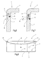
- a circumferential seal 35 may be provided on the cover 3 or alternatively also on the container 2 on the parting line 4, a circumferential seal 35, as it FIGS. 6 and 7 show schematically.
- the seal 35 may be inserted in a recess of the container 2 or the lid 3, injected there or otherwise secured.
- the seal may consist of an elastomer or else an adhesive material, which produces a moisture-tight connection between the lid 3 and the container 2.
- FIG. 7 further illustrates that between the lid 3 and the container 2, a locking means 36 may be effective.
- This is formed, for example, by some elastic springy interlocking means.
- a projection 37 which is formed on the lid 3, and an associated latching opening 38 in the edge projection 34 belong.
- this latching means 36 extends only over portions of the round edge of the container 2 or lid 3.
- the lid 3 can, as the figures illustrate, be formed as a simple slip-on lid whose function lies only in the closure of the interior 10. However, he can fulfill additional and additional functions, such as the function of fixing the felting needles 24.
- a spring element 39 may be provided. This can be formed by a plastic strip, which occupies the width of the lid more or less and, for example, from a narrow-side end 40 to the opposite narrow side End 41 extends.
- the ends 42, 43 of the spring element 39 can sit in corresponding pockets formed on the inside of the cover 3 in order to support themselves there.
- the spring element 39 is, for example, a spiral spring which bulges bulgingly into the interior 10. It is possible for the spring element 39 to be loosely and longitudinally displaceable with both ends in receiving pockets or to be stored on other storage means. Further, the spring element 39 can be firmly connected at one end to the lid 3 and be free at its other end.
- the interior 10 may be provided at one or more locations various depots 44, 45, 46, 47 of rust inhibitors, preservatives or other means to act during the storage time of the felting needles 24 on this.
- These depots are preferably arranged on the bottom 9, one of the side walls, for example the side wall 5, the partition wall 11, the lid 3 and / or the spring element 39 or other locations in the interior 10 of the felt-tip package 1 so as to be removed as needed can be to supply the felted needle 1 to the plastic recycling.
- the felt-tip package 1 is used as follows:
- each of the interior sections 21, 22 is filled with a bundle 29 consisting of felting needles 24.
- These can for example be provided with a paper band or loosely inserted.
- the bundle 29 and the not further illustrated other bundles are preferably oriented in opposite directions.
- the lid 3 is closed. He locked it with the container. 2 and thus hermetically closes the felting needles 24 to the outside.
- the felting needles 24 are urged in the box. Due to the flank contact, they preferably do not abut the outer wall 5 or 7 with their pointed ends of the working parts 25.
- the filling piece 17 can provide further protection for the working parts 25 of the felting needles 24.
- the container 2 may be provided with ribs or other protrusions 8a, 8b on its inside walls, for example, which improve the storage of the felting needles.
- the felted needle package 1 can be shipped and stored in the closed state. If necessary, it is opened, wherein the locking means 36 must be overcome. Preferably, they are designed so that they experience a certain destruction, so that the felting needle 1 is no longer permanently closed. This is used as an originality indicator.
- the felting needles 24 can now be removed individually or in bundles. The opening 12 facilitates removal from the interior 10th
- a felted needle package 1 consists of a cuboid box, the interior of which is subdivided by a dividing wall 11 running obliquely to the side walls but at right angles to the bottom 10.
- the partition wall 11 may have one or more interruptions, such as gripping openings. Other partitions may be provided.
- the partitions separate in the packaging in plan view wedge-shaped, ie prismatic subspaces, which serve to accommodate also wedge-shaped Filznadelbündeln.
Landscapes
- Engineering & Computer Science (AREA)
- Mechanical Engineering (AREA)
- Textile Engineering (AREA)
- Food Science & Technology (AREA)
- Packaging Of Annular Or Rod-Shaped Articles, Wearing Apparel, Cassettes, Or The Like (AREA)
- Nonwoven Fabrics (AREA)
- Details Of Rigid Or Semi-Rigid Containers (AREA)
- Wrappers (AREA)
- Dental Preparations (AREA)
- Organic Insulating Materials (AREA)
- Superconductors And Manufacturing Methods Therefor (AREA)
Abstract
Description
- Die Erfindung betrifft eine Filznadelverpackung.
- Filznadeln werden von Filzherstellern in sehr großer Anzahl benötigt. Sie sind Verschleißteile, die auf Vorrat gekauft und bereitgehalten und bei Bedarf eingesetzt werden. Dabei besteht seitens des Nadelherstellers das Problem, Filznadeln auf rationelle Weise so zu verpacken, dass sie in der Verpackung auch bei rauer Behandlung keinen Schaden nehmen und auf Dauer gelagert werden können. Sie sollen dabei aber auch so verpackt werden, dass die Entnahme der Filznadeln aus der Verpackung seitens des Nadelverbrauchers leicht möglich ist. Verletzungsgefahren sollen dabei minimiert werden.
- Die Filznadeln weisen einen länglichen Arbeitsteil und einen sich in Verlängerung desselben erstreckenden Halteteil mit abgewinkeltem Fuß auf. Die Arbeitsteile haben in der Regel einen geringeren Durchmesser als die Halteteile. Werden die Filznadeln Seite an Seite angeordnet und parallel orientiert, sowie zusammengedrückt, ergibt sich ein keilförmiges Bündel.
- Entsprechend schlägt die
DE 10 2005 036 329 A1 keilförmige Nadelverpackungen vor, von denen die Filznadel geordnet aufgenommen werden. Die keilförmige Verpackung kann in eine rechteckige Umverpackung eingesetzt werden. Dabei schlägt die genannte Schrift auch vor, zwei keilförmige Verpackungen in dem Innenraum der Umverpackung gegensinnig orientiert anzuordnen, um den Innenraum besser zu nutzen. Die verbleibenden Hohlräume der Umverpackung werden mit Schaumstoffkörpern oder dergleichen ausgefüllt. - Weitere Verpackungen sind beispielsweise zur Verpackung von Nähnadeln bekannt. Dazu wird auf die
WO 02/059016 A1 - Davon ausgehend, ist es Aufgabe der Erfindung, eine Platz sparende Filznadelverpackung zu schaffen, die einfach und übersichtlich aufgebaut ist und sowohl herstellerseitig als auch nadelverbraucherseitig einfach zu handhaben ist.
- Diese Aufgabe wird mit der Filznadelverpackung nach Anspruch 1 gelöst:
- Die erfindungsgemäße Filznadelverpackung weist einen Behälter mit einem Boden und von diesen aufragenden Wänden auf, die zusammen mit einem Deckel einen Innenraum zur Aufnahme von Filznadeln umschließen. In dem Innenraum ist mindestens eine Trennwand angeordnet, die in spitzem Winkel zu den Seitenwänden orientiert ist. Diese Trennwand unterteilt den Innenraum des Behälters in zwei oder mehrere, vorzugsweise gleich große, Aufnahmebereiche für Filznadeln. In der Draufsicht, d.h. beim Blick in den Behälter hinein, ist diese Trennwand ungefähr diagonal zwischen zwei der vier Ecken angeordnet. Die Höhe der Trennwand kann im Wesentlichen der Höhe des Behälters entsprechen oder auch geringfügig geringer sein. Durch die schräg angeordnete Trennwand wird der Innenraum des Behälters in mehrere, im Wesentlichen keilförmige Abteilungen unterteilt, wobei die Keilform an die Verjüngung der Filznadeln angepasst sein kann.
- In der erfindungsgemäßen Filznadelverpackung liegen die Filznadeln vorzugsweise gleichsinnig orientiert in dem jeweiligen abgeteilten Abschnitt des Innenraums beieinander. Die Arbeitsteile der Nadeln der betreffenden Abteilung zeigen in eine erste Richtung. Die Halteteile zeigen in eine zweite entgegen gesetzte Richtung. Die Nadeln des Nadelbündels des anderen von der Trennwand abgeteilten Aufnahmebereichs sind vorzugsweise entgegen gerichtet orientiert.
- Vorzugsweise ist die Trennwand mit mindestens einer Ausnehmung versehen, die beispielsweise mittig angeordnet ist und von ihrem oberen Rand bis zum Boden durchgehen kann. Diese oder auch eine kleinere Ausnehmung erleichtert das Herausnehmen der Filznadeln aus der Verpackung und regt den Bediener dazu an, die Nadeln mittig zu ergreifen. Dies reduziert die Gefahr der Verletzung durch Berührung der häufig sehr spitzen oder scharfkantigen Arbeitsteile, da diese Arbeitsteile im Endbereich der Nadeln angeordnet sind.
- Bei Bedarf kann in den Behälter ein zusätzliches Teil, beispielsweise in Form eines Winkelstücks, eingesetzt werden, um den Aufnahmeraum an seiner jeweiligen Spitze zu verkürzen.
- Diese Maßnahme kann beispielsweise zur Anpassung an kürzere Nadeln genutzt werden.
- Die Trennwand ist vorzugsweise mindestens mit der Seitenwand und/oder dem Boden, weiter vorzugsweise sowohl mit der Seitenwand als auch mit dem Boden verbunden, wodurch sich eine stabile Position der Trennwand in dem Behälter ergibt. In Einzelfällen kann es auch zweckmäßig sein, die Trennwand nur mit dem Boden oder nur mit der Seitenwand zu verbinden, um eine Flexibilität in der einen oder anderen Biegerichtung zu erzielen.
- Die Trennwand und/oder das Winkelstück können einstückig, nahtlos mit Behälter, dessen Boden und/oder wenigstens einer Wand verbunden sein. Der Behälter ist dann aus einem Teil gebildet.
- Vorzugsweise bestehen der Behälter und sein Deckel aus und dem gleichen Kunststoff. Auch ist die Trennwand vorzugsweise aus dem gleichen Kunststoff ausgebildet und beispielsweise mit dem übrigen Behälter einstückig und nahtlos verbunden. Das oben genannte Winkelstück oder sonstige Einsatzteil besteht vorzugsweise ebenfalls aus dem gleichen Kunststoff. Diese Maßnahme kommt dem Recycling entgegen. Vorzugsweise bestehen der Behälter und sein Deckel aus einem leicht recycelbaren Kunststoff, wie beispielsweise Polystyrol oder ABS.
- Der Deckel ist vorzugsweise als Multifunktionsdeckel ausgebildet. Er kann an dem Behälter an einer Winkelfuge anschließen, bei der der Behälter und der Deckel entlang des Behälterrands ineinander greifen. Zur Verbesserung der Abdichtung kann eine weiche Dichtung in den Deckel oder auch in den oberen Rand des Behälters integriert sein. Ein gesondertes, den Behälter außen umfassendes Klebeband kann dann entfallen.
- Der Deckel kann mit dem Rand des Behälters verrastet werden. Vorzugsweise können dort Rastmittel oder Clips vorgesehen werden, die sich nur durch Zerstörung öffnen lassen. Der Clip dient dann als Originalitätsverschluss.
- Es ist möglich in der Verpackung ein Rostschutzdepot vorzusehen. Dieses kann in dem Deckel oder ersatzweise auch an anderer Stelle in dem Behälter untergebracht werden. Vorzugsweise handelt es sich bei dem Depot um ein Rostschutzmittel in einer für die Automation geeigneten Form. Es kann beispielsweise in Form von Tabletten, in Form eines Gels, in Form kleiner Pulversäcke, getränkten Papiers, Pappstücke oder Vlies, usw., vorgesehen werden. Vorzugsweise ist das Depot mit den genannten Teilen des Deckels oder des Behälters nur haftend verbunden, um bedarfsweise vor dem Recycling entfernt werden zu können.
- Obwohl der Behälter außen eine Quaderform hat, ist sein Innenraum in keilförmige Kammern unterteilt. Die Anzahl der Kammern ist Zwei oder größer. Der Grundriss der Kammer kann ein Dreieck oder Trapez (Dreieck mit abgeschnittener Spitze) sein, wobei die Kammern durch eine oder mehrere Trennwände im Innenraum des nach oben offenen Behälters gebildet werden. Die Trennwände verlaufen, wie die Seitenwände des Behälters, vorzugsweise senkrecht, d.h. rechtwinklig zu dem Boden.
- Zur Fixierung der Nadeln kann eine im Deckel angebrachte Feder dienen. Diese Feder kann durch eine Kunststoffplatte oder einen Kunststoffstreifen oder ein sonstiges ähnliches Element gebildet werden, der mit einem oder vorzugsweise beiden Enden an dem Deckel abgestützt ist und der sich zu den Nadeln, d.h. in den Behälterinnenraum hinein wölbt.
- Weiter können an den Wänden des Behälters und/oder an seinem Boden Rippen oder sonstige Vorsprünge vorgesehen sein, um eine gute Anlage der Nadeln in dem Behälter zu ermöglichen.
- Weitere Einzelheiten vorteilhafter Ausführungsformen der Erfindung ergeben sich aus der Zeichnung, Ansprüchen oder der Beschreibung. Die Beschreibung beschränkt sich auf wesentliche Aspekte der Erfindung und sonstige Gegebenheiten. Die Zeichnung ist ergänzend heranzuziehen. Sie offenbart weitere Details. Es zeigen:
-
Fig. 1 eine Filznadelverpackung in geschlossenem Zustand, in perspektivischer Darstellung, -
Fig. 2 die Filznadelverpackung nachFigur 1 mit abgenommenen Deckel, in perspektivischer Ansicht, -
Fig. 3 eine Filznadel aus der Verpackung nachFigur 1 oder 2 , in schematischer Seitenansicht, -
Fig. 4 den Behälter der Filznadelverpackung nachFigur 2 , in schematischer Draufsicht, -
Fig. 5 den Behälter nachFigur 4 , in geschnittener Ansicht, geschnitten entlang der Linie V-V inFigur 4 , -
Fig. 6 und 7 die Filznadelverpackung, geschnitten an der Fuge zwischen Deckel und Behälter an zwei unterschiedlichen Stellen, und -
Fig. 8 die Nadelverpackung nachFigur 1 im Vertikalschnitt in einer abgewandelten Ausführungsform. - In
Figur 1 ist eine Filznadelverpackung 1 veranschaulicht, die als rechteckige Schachtel ausgebildet ist. Zu ihr gehören ein Behälter 2 und ein Deckel 3 zum Abschluss des Behälters 2 nach oben hin. Der Deckel 3 und der Behälter 2 stoßen an einer Trennfuge 4 aneinander. -
Figur 2 veranschaulicht den Behälter 2 detaillierter. Er umfasst vier Seitenwände 5, 6, 7, 8, die einen rechteckigen Innenraum umgrenzen. Sie ragen vorzugsweise im 90° Winkel von einem Boden 9 auf. Der entsprechende 90° Winkel α ist zum Beispiel ausFigur 5 ersichtlich. Der Boden 9 und die Seitenwände 5, 6, 7, 8 sind jeweils rechteckige, dünne, vorzugsweise im Wesentlichen ebene, plattenförmige Elemente, die aus dem gleichen Material bestehen und an ihren Kanten fugen- und nahtlos aneinander anschließen. Der Behälter 2 kann beispielsweise ein Kunststoff-Spritzgussteil sein. Vorzugsweise besteht er aus einem recyclingfähigen Kunststoff. - Der von dem Behälter 2 umschlossene Innenraum 10 ist durch eine Trennwand 11 schräg unterteilt. Die Trennwand 11 ist vorzugsweise einstückiger Bestandteil des Behälters 2. Sie ist in diesem Fall wiederum fugen- und nahtlos sowohl mit dem Boden 9 als auch mit zumindest einer der Seitenwände 5, 6, 7, 8 verbunden. Die Trennwand 11 kann mittig mit einer Öffnung 12 versehen sein, die bis zu dem Boden 9 durchgeht und sie somit in zwei Trennwandabschnitte 13, 14 unterteilt. Vorzugsweise fluchten diese miteinander und liegen somit im Wesentlich in einer gemeinsamen Ebene bzw. (siehe
Figur 4 ) auf einer gemeinsamen Linie. Diese Ebene oder Linie schneidet einander gegenüberliegende Seitenwände 5, 7 und liegt zumindest nahe bei der Diagonalen des von dem Boden 9 beschriebenen Rechtecks. Entsprechend schließen die Trennwand 11 und der Trennwandabschnitt 13 an die kleinere Seitenwand 7 an. Entsprechendes gilt für den Trennwandabschnitt 14, der an die kleinere Seitenwand 5 anschließt. Die größeren Seitenwände 6, 8 haben vorzugsweise keine anschließenden Trennwände. Der Trennwandabschnitt 13 schließt mit der Seitenwand 7 einen Winkel β ein, der kleiner als 90° ist. Mit der langen Seitenwand 8 schließt der Trennwandabschnitt 13 ebenfalls einen Winkel γ ein, der kleiner als 90° ist. Die Summe der beiden Winkel β und γ beträgt 90°. Mit dem Boden 9 schließt die Trennwand 11 im Ganzen und insbesondere der Trennwandabschnitt 14 bzw. 13 einen rechten Winkel δ ein (sieheFigur 5 ) . - Der im Wesentlichen ebene Trennwandabschnitt 13 kann an seiner der Öffnung 12 zugewandten Kante mit einem abgewinkelten Rand 15 versehen sein, der die Steifigkeit des Trennwandabschnitts 13 erhöht. Außerdem kann der Trennwandabschnitt 13 mit einer zu dem Rand 15 parallel verlaufenden Sicke 16 versehen sein, die eine der langen Seitenwand 6, 8 zugewandte Nut definiert. Diese Nut kann der Aufnahme eines Füllstücks 17 dienen, das beispielsweise als Winkelstück ausgebildet ist. Seine beiden Abschnitte 18, 19 die vorzugsweise die gleiche Geometrie und/oder Länge aufweisen schließen miteinander vorzugsweise einen rechten Winkel ein. Das Füllstück 17 kann von oben her in den Zwischenraum zwischen dem Trennwandabschnitt 13 und der langen Seitenwand 8 eingeschoben werden, wobei die Stirnseite des Abschnitts 18 in die Sicke 16 findet und eine Flachseite des Abschnitts 19 an der Seitenwand 8 anliegt.
- Wie
Figur 4 veranschaulicht, unterteilt die Trennwand 11 den Innenraum 10 in zwei Innenraumabschnitte 20, 21. Diese haben jeweils einen ungefähr dreieckigen Grundriss. Wenn die Trennwand 11 an die Ecken 22, 23 anschließt, ist der jeweilige Innenraumabschnitt 20, 21 exakt dreieckig. Ansonsten ist er, wie dargestellt, trapezförmig ausgebildet. Seine Länge kann durch das Füllstück 17 variiert werden, um eine Anpassung an verschieden lange Filznadeln vorzunehmen. -
Figur 3 veranschaulicht eine Filznadel 24 wie sie in großer Anzahl von der Filznadelverpackung 1 aufzunehmen ist. Sie weist einen Arbeitsteil 25 der an einem Ende eine Spitze und am gegenüberliegenden Ende einem sich an den Arbeitsteil 25 in gerader Verlängerung anschließenden dickeren Schaft 26 und einem Halteteil 27 auf, das sich wiederum in gerader Verlängerung an den Schaft 26 anschließt, dabei jedoch eine größere Dicke als der Schaft 26 aufweist. Das Ende des Halteteils 27 kann abgewinkelt sein, um einen Fuß 28 zu bilden. Solche Filznadeln bilden, wenn sie mit gleicher Orientierung Seite an Seite aneinander gelegt werden, ein keilförmiges Bündel 29. Ein solches ist inFigur 2 lediglich durch einige Linien schematisch angedeutet. Das Bündel 29 füllt den Innenraumabschnitt 20 weitgehend aus. Der Innenraumabschnitt 21 kann ein entgegengesetzt orientiertes ebenfalls keilförmiges Bündel von Filznadeln 24 aufnehmen, was jedoch inFigur 2 nicht näher veranschaulicht ist. - Die Verbindung zwischen dem Deckel 3 und dem Behälter 2 der Filznadelverpackung 1 ist vorzugsweise feuchtigkeitsdicht ausgebildet. Dazu kann die Trennfuge 4, wie die
Figuren 6 und 7 veranschaulichen, insbesondere als Winkelfuge ausgebildet sein. Dies bedeutet, dass die Fuge mehrere Flächen umfasst, die an mindestens einer, vorzugsweise mehreren, Linien 30, 31, 32 miteinander jeweils einen Winkel einschließen. Damit kann zum Beispiel der Deckel 3 eine Nut 33 aufweisen, in die ein Randvorsprung 34 des Behälters 2 ragt. An geeigneter Stelle kann an dem Deckel 3 oder alternativ auch an dem Behälter 2 an der Trennfuge 4 eine ringsum laufende Dichtung 35 vorgesehen sein, wie esFigur 6 und 7 schematisch zeigen. Die Dichtung 35 kann in einer Ausnehmung des Behälters 2 oder des Deckels 3 eingelegt, dort eingespritzt oder anderweitig befestigt sein. Die Dichtung kann aus einem Elastomer oder auch einem verklebenden Material bestehen, das eine feuchtigkeitsdichte Verbindung zwischen dem Deckel 3 und dem Behälter 2 herstellt. -
Figur 7 veranschaulicht weiter, dass zwischen dem Deckel 3 und dem Behälter 2 ein Rastmittel 36 wirksam sein kann. Dieses wird beispielsweise durch etwas elastische federnachgiebige ineinander greifende Mittel gebildet. Zu diesem können beispielsweise ein Vorsprung 37, der an dem Deckel 3 ausgebildet ist, und eine zugeordnete Rastöffnung 38 in dem Randvorsprung 34 gehören. Vorzugsweise erstreckt sich dieses Rastmittel 36 lediglich über Abschnitte des ringsum laufenden Rands des Behälters 2 bzw. Deckels 3. - Der Deckel 3 kann, wie die Figuren veranschaulichen, als einfacher Stülpdeckel ausgebildet sein, dessen Funktion lediglich in dem Verschluss des Innenraums 10 liegt. Er kann jedoch weitere und zusätzliche Funktionen erfüllen, beispielsweise die Funktion der Fixierung der Filznadeln 24. Dazu kann an dem Deckel 3, wie es
Figur 8 veranschaulicht, ein Federelement 39 vorgesehen sein. Dieses kann durch einen Kunststoffstreifen gebildet sein, der die Breite des Deckels mehr oder weniger einnimmt und sich zum Beispiel von einem schmalseitigen Ende 40 zu dem gegenüber liegenden schmalseitigen Ende 41 erstreckt. Die Enden 42, 43 des Federelements 39 können in entsprechenden innenseitig an dem Deckel 3 ausgebildeten Taschen sitzen, um sich dort abzustützen. Das Federelement 39 ist beispielsweise eine Biegefeder, die sich in den Innenraum 10 bauchig vorwölbt. Es ist möglich das Federelement 39 lose und längs verschiebbar mit beiden Enden in Aufnahmetaschen aufzunehmen oder an sonstigen Lagermitteln zu lagern. Weiter kann das Federelement 39 an einem Ende fest mit dem Deckel 3 verbunden und an seinem anderen Ende frei sein. - Der Innenraum 10 kann an einer oder mehreren Stellen verschiedene Depots 44, 45, 46, 47 von Rostschutzmittel, Konservierungsmittel oder anderen Mitteln versehen sein, die während der Lagerzeit der Filznadeln 24 auf diese einwirken sollen. Diese Depots sind vorzugsweise an dem Boden 9, eine der Seitenwände, zum Beispiel der Seitenwand 5, der Trennwand 11, dem Deckel 3 und/oder dem Federelement 39 oder anderen Stellen in dem Innenraum 10 der Filznadelverpackung 1 so angeordnet, dass sie bei Bedarf entfernt werden können, um die Filznadelverpackung 1 dem Kunststoffrecycling zuzuführen.
- Zum Bestücken wird jeder der Innenraumabschnitte 21, 22 mit einem Bündel 29 bestehend aus Filznadeln 24 gefüllt. Diese können beispielsweise mit einer Papierbanderole versehen sein oder auch lose eingelegt werden. Das Bündel 29 und das nicht weiter veranschaulichte andere Bündel werden dabei vorzugsweise gegensinnig orientiert. Ist dies geschehen, wird der Deckel 3 geschlossen. Er verrastet dabei mit dem Behälter 2 und schließt somit die Filznadeln 24 nach außen hermetisch ab.
- Die Filznadeln 24 liegen gedrängt in der Schachtel. Aufgrund der Flankenberührung stoßen sie vorzugsweise mit ihren spitzen Enden der Arbeitsteile 25 nicht an die Außenwand 5 bzw. 7. Außerdem kann das Füllstück 17 einen weiteren Schutz der Arbeitsteile 25 der Filznadeln 24 erbringen. Wie
Figur 4 veranschaulicht, kann der Behälter 2 außerdem zum Beispiel an seinen Seitenwänden innen mit Rippen oder sonstigen Vorsprüngen 8a, 8b versehen sein, die die Lagerung der Filznadeln verbessern. - Die Filznadelverpackung 1 kann in geschlossenem Zustand versandt und gelagert werden. Bei Bedarf wird sie geöffnet, wobei die Rastmittel 36 überwunden werden müssen. Vorzugsweise sind sie so beschaffen, dass sie dabei eine gewisse Zerstörung erfahren, so dass die Filznadelverpackung 1 nicht mehr dauerhaft fest verschließbar ist. Dies wird als Originalitätskennzeichen genutzt. Die Filznadeln 24 können nun einzeln oder bündelweise entnommen werden. Die Öffnung 12 erleichtert das Herausnehmen aus dem Innenraum 10.
- Eine erfindungsgemäße Filznadelverpackung 1 besteht aus einer quaderförmigen Schachtel, deren Innenraum durch eine schräg zu den Seitenwänden, aber rechtwinklig zu dem Boden 10 verlaufende Trennwand 11 unterteilt ist. Die Trennwand 11 kann eine oder mehrere Unterbrechungen, wie beispielsweise Greiföffnungen, aufweisen. Weitere Trennwände können vorgesehen sein. Die Trennwände trennen in der Verpackung in Draufsicht keilförmige, d.h. prismatische Teilräume ab, die zur Aufnahme von ebenfalls keilförmigen Filznadelbündeln dienen.
-
- 1
- Filznadelverpackung
- 2
- Behälter
- 3
- Deckel
- 4
- Trennfuge
- 5,6,7,8
- Seitenwände
- 8a, 8b
- Vorsprünge, Rippen
- 9
- Boden
- α
- Winkel
- 10
- Innenraum
- 11
- Trennwand
- 12
- Öffnung
- 13, 14
- Trennwandabschnitte
- β, γ, δ
- Winkel
- 15
- Rand
- 16
- Nut
- 17
- Füllstück
- 18, 19
- Abschnitte
- 20, 21
- Innenraumabschnitte, Nadelaufnahmeraum, Kammern
- 22, 23
- Ecke
- 24
- Filznadel
- 25
- Arbeitsteil
- 26
- Schaft
- 27
- Halteteil
- 28
- Fuß
- 29
- Bündel
- 30,31,32
- Linien
- 33
- Nut
- 34
- Randvorsprung
- 35
- Dichtung
- 36
- Rastmittel
- 37
- Rastvorsprung
- 38
- Rastöffnung
- 39
- Federelement, Niederhalter
- 40,41,42,43
- Enden
- 44,45,46,47
- Depots
Claims (15)
- Filznadelverpackung (1)
mit einem Behälter (2), der einen Boden (9) und sich von dem Boden (9) aufragende Wände (5, 6, 7, 8) aufweist, die zusammen mit einem Deckel (3) einen Innenraum (10) zur Aufnahme von Filznadeln (24) umschließen, und
mit mindestens einer Trennwand (11), die in einem spitzen Winkel (β) zu einer benachbarten Seitenwand (5, 7) orientiert und in dem Innenraum (10) angeordnet ist. - Filznadelverpackung nach Anspruch 1, dadurch gekennzeichnet, dass auf beiden Seiten der Trennwand (11) jeweils mindestens ein Nadelaufnahmeraum (20, 21) festgelegt ist, der an einer Seite von einer Seitenwand (6, 8) und an der gegenüberliegenden Seite von der Trennwand (11) begrenzt ist.
- Filznadelverpackung nach Anspruch 1, dadurch gekennzeichnet, dass die Trennwand (11) in dem Innenraum (10) keilförmige Kammern (20, 21) abtrennt.
- Filznadelverpackung nach Anspruch 1, dadurch gekennzeichnet, dass die Trennwand (11) mit dem Boden (9) und/oder zumindest einer Seitenwand (7) verbunden ist.
- Filznadelverpackung nach Anspruch 1, dadurch gekennzeichnet, dass der Boden (9) rechteckig ausgebildet ist.
- Filznadelverpackung nach Anspruch 1, dadurch gekennzeichnet, dass die Seitenwände (5, 6, 7, 8) mit dem Boden (9) jeweils einen rechten Winkel (α) einschließen.
- Filznadelverpackung nach Anspruch 1, dadurch gekennzeichnet, dass sich die Trennwand (11) von einer Ecke (22), an der zwei Seitenwände (7, 8) aneinander stoßen, oder von einem eckennahen Bereich einer Seitenwand (7) ausgehend zu der gegenüberliegenden Ecke (23) oder Seitenwand (5) erstreckt.
- Filznadelverpackung nach Anspruch 1, dadurch gekennzeichnet, dass die Trennwand (11) mindestens eine Ausnehmung (12) aufweist.
- Filznadelverpackung nach Anspruch 8, dadurch gekennzeichnet, dass die Ausnehmung (12) als Durchbruch in einem mittleren Abschnitt der Trennwand (11) angeordnet ist.
- Filznadelverpackung nach Anspruch 1, dadurch gekennzeichnet, dass der Deckel (3) mit den Seitenwänden (5, 6, 7, 8) über eine Winkelfuge (4) verbunden ist.
- Filznadelverpackung nach Anspruch 1, dadurch gekennzeichnet, dass der Deckel (3) und die Seitenwände (5, 6, 7, 8) über mindestens ein Rastmittel (36) miteinander verbunden sind.
- Filznadelverpackung nach Anspruch 1, dadurch gekennzeichnet, dass der Deckel (3) und/oder die Seitenwände (5, 6, 7, 8) mit einer integrierten Dichtung (35) verbunden sind.
- Filznadelverpackung nach Anspruch 1, dadurch gekennzeichnet, dass in dem Deckel (3) und/oder an dem Boden (9) und/oder an den Seitenwänden (5, 6, 7, 8) und/oder an der Trennwand (11) ein Depot eines Behandlungsmittels oder Konservierungsmittels angeordnet ist.
- Filznadelverpackung nach Anspruch 1, dadurch gekennzeichnet, dass an dem Deckel (3) ein Niederhalter (39) vorgesehen ist.
- Filznadelverpackung nach Anspruch 1, dadurch gekennzeichnet, dass der Niederhalter (39) durch eine Biegefeder mit zwei Enden (42, 43) gebildet ist, die beide an dem Deckel (3) abgestützt sind.
Priority Applications (13)
| Application Number | Priority Date | Filing Date | Title |
|---|---|---|---|
| EP20080156671 EP2123574B1 (de) | 2008-05-21 | 2008-05-21 | Filznadelverpackung |
| DE200850001714 DE502008001714D1 (de) | 2008-05-21 | 2008-05-21 | Filznadelverpackung |
| PL08156671T PL2123574T3 (pl) | 2008-05-21 | 2008-05-21 | Opakowanie igieł spilśniających |
| AT08156671T ATE486799T1 (de) | 2008-05-21 | 2008-05-21 | Filznadelverpackung |
| PT08156671T PT2123574E (pt) | 2008-05-21 | 2008-05-21 | Embalagem para agulhas de feltragem |
| ES08156671T ES2355424T3 (es) | 2008-05-21 | 2008-05-21 | Embalaje de agujas para fieltro. |
| BRPI0901538-8A BRPI0901538B1 (pt) | 2008-05-21 | 2009-05-14 | Estojo de agulha de feltragem |
| JP2009120415A JP5042273B2 (ja) | 2008-05-21 | 2009-05-18 | フェルト針パッケージ |
| KR1020090043382A KR101097032B1 (ko) | 2008-05-21 | 2009-05-19 | 펠트제 니들 패키지 |
| TW098116633A TWI370091B (en) | 2008-05-21 | 2009-05-20 | Felting needle package |
| RU2009119166A RU2420444C2 (ru) | 2008-05-21 | 2009-05-20 | Упаковка игл для валяния |
| US12/469,560 US8038005B2 (en) | 2008-05-21 | 2009-05-20 | Felting needle package |
| CN200910139000.9A CN101585438B (zh) | 2008-05-21 | 2009-05-21 | 制毡针包装 |
Applications Claiming Priority (1)
| Application Number | Priority Date | Filing Date | Title |
|---|---|---|---|
| EP20080156671 EP2123574B1 (de) | 2008-05-21 | 2008-05-21 | Filznadelverpackung |
Publications (2)
| Publication Number | Publication Date |
|---|---|
| EP2123574A1 true EP2123574A1 (de) | 2009-11-25 |
| EP2123574B1 EP2123574B1 (de) | 2010-11-03 |
Family
ID=39529773
Family Applications (1)
| Application Number | Title | Priority Date | Filing Date |
|---|---|---|---|
| EP20080156671 Active EP2123574B1 (de) | 2008-05-21 | 2008-05-21 | Filznadelverpackung |
Country Status (13)
| Country | Link |
|---|---|
| US (1) | US8038005B2 (de) |
| EP (1) | EP2123574B1 (de) |
| JP (1) | JP5042273B2 (de) |
| KR (1) | KR101097032B1 (de) |
| CN (1) | CN101585438B (de) |
| AT (1) | ATE486799T1 (de) |
| BR (1) | BRPI0901538B1 (de) |
| DE (1) | DE502008001714D1 (de) |
| ES (1) | ES2355424T3 (de) |
| PL (1) | PL2123574T3 (de) |
| PT (1) | PT2123574E (de) |
| RU (1) | RU2420444C2 (de) |
| TW (1) | TWI370091B (de) |
Citations (4)
| Publication number | Priority date | Publication date | Assignee | Title |
|---|---|---|---|---|
| FR1157155A (fr) | 1956-08-03 | 1958-05-27 | Boîte distributrice d'épingles | |
| DE9209580U1 (de) * | 1992-07-17 | 1992-11-12 | Theodor Groz & Söhne & Ernst Beckert Nadelfabrik KG, 7470 Albstadt | Verpackungs- und Aufbewahrungsbehältnis für Strickmaschinennadeln |
| WO2002059016A1 (de) | 2001-01-24 | 2002-08-01 | Groz-Beckert Kg | Nadelverpackung |
| DE102005036329A1 (de) | 2005-07-29 | 2007-02-01 | Groz-Beckert Kg | Filznadelverpackung |
Family Cites Families (18)
| Publication number | Priority date | Publication date | Assignee | Title |
|---|---|---|---|---|
| US1674352A (en) * | 1926-05-25 | 1928-06-19 | Adjustable Gun Case Corp | Gun case |
| US1799776A (en) * | 1927-07-20 | 1931-04-07 | Scovill Manufacturing Co | Package for pins |
| US2417331A (en) * | 1946-02-08 | 1947-03-11 | Glenn L Martin Co | Gun storage container |
| US3410391A (en) * | 1967-07-06 | 1968-11-12 | Hanson Whitney Company | Storage and shipping container |
| US3491909A (en) * | 1968-04-25 | 1970-01-27 | Gerald S Ikelheimer | Partitioned carrying case |
| US3758020A (en) * | 1971-10-19 | 1973-09-11 | Corrugated Prod Ltd | Pack for articles |
| SU1406060A1 (ru) * | 1986-12-02 | 1988-06-30 | Производственное Объединение "Полимер" | Герметична тара |
| JPH01130969A (ja) | 1987-11-16 | 1989-05-23 | Fuji Kagakushi Kogyo Co Ltd | シリアル型熱転写プリント方法 |
| SU1745622A1 (ru) * | 1989-10-23 | 1992-07-07 | Пензенский Филиал Научно-Исследовательского И Конструкторско-Технологического Института Местной Промышленности | Коробка |
| DE20006093U1 (de) | 2000-04-01 | 2000-09-14 | Jokey Plastik Gummersbach GmbH, 51645 Gummersbach | Kunststoffbehälter mit einrastbarem Deckel |
| US20020094942A1 (en) | 2000-09-06 | 2002-07-18 | The Procter & Gamble Company | Fabric additive articles and package therefor |
| JP2002146616A (ja) * | 2000-11-10 | 2002-05-22 | Kobun Shoin:Kk | 小型裁縫箱 |
| US20040211822A1 (en) * | 2003-04-22 | 2004-10-28 | Mao-Chia Lin | Shoe box |
| JP4584659B2 (ja) * | 2003-09-30 | 2010-11-24 | 株式会社リコー | 画像形成用粉体を内包する易変形性容器用容器収納箱 |
| RU50521U1 (ru) * | 2004-01-19 | 2006-01-20 | Дмитрий Александрович Шинкарюк | Герметичный пакет для мелкоштучных, готовых к употреблению маслянистых продуктов |
| KR20060000132A (ko) | 2004-06-28 | 2006-01-06 | (주)이우테크놀로지 | 환자의 주의사항 및 처방전을 자동으로 인쇄하여 제공하는방법 및 프로그램 |
| US20060124712A1 (en) * | 2004-12-14 | 2006-06-15 | Weimer Charles P Jr | Shipping and display tray |
| CN201031017Y (zh) | 2007-03-09 | 2008-03-05 | 孟娇 | 一种瓶盖 |
-
2008
- 2008-05-21 EP EP20080156671 patent/EP2123574B1/de active Active
- 2008-05-21 PL PL08156671T patent/PL2123574T3/pl unknown
- 2008-05-21 DE DE200850001714 patent/DE502008001714D1/de active Active
- 2008-05-21 ES ES08156671T patent/ES2355424T3/es active Active
- 2008-05-21 AT AT08156671T patent/ATE486799T1/de active
- 2008-05-21 PT PT08156671T patent/PT2123574E/pt unknown
-
2009
- 2009-05-14 BR BRPI0901538-8A patent/BRPI0901538B1/pt active IP Right Grant
- 2009-05-18 JP JP2009120415A patent/JP5042273B2/ja active Active
- 2009-05-19 KR KR1020090043382A patent/KR101097032B1/ko active Active
- 2009-05-20 RU RU2009119166A patent/RU2420444C2/ru active
- 2009-05-20 TW TW098116633A patent/TWI370091B/zh active
- 2009-05-20 US US12/469,560 patent/US8038005B2/en active Active
- 2009-05-21 CN CN200910139000.9A patent/CN101585438B/zh active Active
Patent Citations (4)
| Publication number | Priority date | Publication date | Assignee | Title |
|---|---|---|---|---|
| FR1157155A (fr) | 1956-08-03 | 1958-05-27 | Boîte distributrice d'épingles | |
| DE9209580U1 (de) * | 1992-07-17 | 1992-11-12 | Theodor Groz & Söhne & Ernst Beckert Nadelfabrik KG, 7470 Albstadt | Verpackungs- und Aufbewahrungsbehältnis für Strickmaschinennadeln |
| WO2002059016A1 (de) | 2001-01-24 | 2002-08-01 | Groz-Beckert Kg | Nadelverpackung |
| DE102005036329A1 (de) | 2005-07-29 | 2007-02-01 | Groz-Beckert Kg | Filznadelverpackung |
Also Published As
| Publication number | Publication date |
|---|---|
| CN101585438A (zh) | 2009-11-25 |
| US8038005B2 (en) | 2011-10-18 |
| RU2420444C2 (ru) | 2011-06-10 |
| DE502008001714D1 (de) | 2010-12-16 |
| KR101097032B1 (ko) | 2011-12-22 |
| TWI370091B (en) | 2012-08-11 |
| TW201016564A (en) | 2010-05-01 |
| PL2123574T3 (pl) | 2011-04-29 |
| JP2010006475A (ja) | 2010-01-14 |
| KR20090121226A (ko) | 2009-11-25 |
| PT2123574E (pt) | 2011-01-24 |
| CN101585438B (zh) | 2015-06-24 |
| ATE486799T1 (de) | 2010-11-15 |
| US20090288975A1 (en) | 2009-11-26 |
| ES2355424T3 (es) | 2011-03-25 |
| EP2123574B1 (de) | 2010-11-03 |
| BRPI0901538B1 (pt) | 2019-03-19 |
| BRPI0901538A2 (pt) | 2010-01-26 |
| JP5042273B2 (ja) | 2012-10-03 |
| RU2009119166A (ru) | 2010-11-27 |
| BRPI0901538A8 (pt) | 2018-07-31 |
Similar Documents
| Publication | Publication Date | Title |
|---|---|---|
| DE60317334T2 (de) | Kartonbehälter für zigarettenpackungen | |
| EP0745541B1 (de) | Klappschachtel für Zigaretten | |
| EP0801010B1 (de) | Klappschachtel, insbesondere für Zigaretten | |
| WO2017129377A1 (de) | Transportbehältersystem und transportbehälter | |
| WO2001012527A1 (de) | Klappschachtel für zigaretten | |
| EP0561737B1 (de) | Verpackung mit integrierter Unterteilung | |
| EP0835827A2 (de) | Quaderförmige Verpackung für Zigaretten sowie Zuschnitt für die Verpackung | |
| EP0625469A2 (de) | Verpackung, nämlich Klappschachtel | |
| DE2519345A1 (de) | Geschlossener karton aus zwei teilen | |
| WO2018036648A1 (de) | Packung für zigaretten | |
| EP0842868B1 (de) | Verpackung, insbesondere für Nähmaschinennadeln oder dergleichen längliche Gegenstände | |
| EP1353862B1 (de) | Nadelverpackung | |
| EP2123574B1 (de) | Filznadelverpackung | |
| DE10141208A1 (de) | Verpackung für mehrere in separaten Einzelverpackungen verpackte Einzelprodukte | |
| DE6919362U (de) | Kartonverpackung | |
| DE4130883A1 (de) | Faltschachtel | |
| DE29705638U1 (de) | Bechereinheit | |
| DE9203448U1 (de) | Zweischalenbehälter | |
| EP1834895B1 (de) | Verpackung | |
| DE3914398A1 (de) | Zweistoff-verpackung, insbesondere zweistoff-fluessigkeitsverpackung mit einem durch eine ausstanzung des aussenkartons nach aussen ziehbaren giessstutzen des innenbehaelters | |
| EP0565018A2 (de) | Verpackungsbehälter | |
| DE10023197A1 (de) | Verpackung und Zuschnitt für eien Verpackungseinsatz | |
| DE3843008A1 (de) | Verpackungsbehaelter | |
| DE4128975C2 (de) | ||
| DE9319229U1 (de) | Blisterpackung |
Legal Events
| Date | Code | Title | Description |
|---|---|---|---|
| PUAI | Public reference made under article 153(3) epc to a published international application that has entered the european phase |
Free format text: ORIGINAL CODE: 0009012 |
|
| AK | Designated contracting states |
Kind code of ref document: A1 Designated state(s): AT BE BG CH CY CZ DE DK EE ES FI FR GB GR HR HU IE IS IT LI LT LU LV MC MT NL NO PL PT RO SE SI SK TR |
|
| AX | Request for extension of the european patent |
Extension state: AL BA MK RS |
|
| 17P | Request for examination filed |
Effective date: 20091222 |
|
| GRAP | Despatch of communication of intention to grant a patent |
Free format text: ORIGINAL CODE: EPIDOSNIGR1 |
|
| AKX | Designation fees paid |
Designated state(s): AT BE BG CH CY CZ DE DK EE ES FI FR GB GR HR HU IE IS IT LI LT LU LV MC MT NL NO PL PT RO SE SI SK TR |
|
| GRAS | Grant fee paid |
Free format text: ORIGINAL CODE: EPIDOSNIGR3 |
|
| GRAA | (expected) grant |
Free format text: ORIGINAL CODE: 0009210 |
|
| AK | Designated contracting states |
Kind code of ref document: B1 Designated state(s): AT BE BG CH CY CZ DE DK EE ES FI FR GB GR HR HU IE IS IT LI LT LU LV MC MT NL NO PL PT RO SE SI SK TR |
|
| REG | Reference to a national code |
Ref country code: GB Ref legal event code: FG4D Free format text: NOT ENGLISH |
|
| REG | Reference to a national code |
Ref country code: CH Ref legal event code: EP |
|
| REG | Reference to a national code |
Ref country code: IE Ref legal event code: FG4D Free format text: LANGUAGE OF EP DOCUMENT: GERMAN |
|
| REF | Corresponds to: |
Ref document number: 502008001714 Country of ref document: DE Date of ref document: 20101216 Kind code of ref document: P |
|
| REG | Reference to a national code |
Ref country code: PT Ref legal event code: SC4A Free format text: AVAILABILITY OF NATIONAL TRANSLATION Effective date: 20110117 |
|
| REG | Reference to a national code |
Ref country code: NL Ref legal event code: VDEP Effective date: 20101103 |
|
| REG | Reference to a national code |
Ref country code: ES Ref legal event code: FG2A Ref document number: 2355424 Country of ref document: ES Kind code of ref document: T3 Effective date: 20110325 |
|
| LTIE | Lt: invalidation of european patent or patent extension |
Effective date: 20101103 |
|
| PG25 | Lapsed in a contracting state [announced via postgrant information from national office to epo] |
Ref country code: NO Free format text: LAPSE BECAUSE OF FAILURE TO SUBMIT A TRANSLATION OF THE DESCRIPTION OR TO PAY THE FEE WITHIN THE PRESCRIBED TIME-LIMIT Effective date: 20110203 Ref country code: LT Free format text: LAPSE BECAUSE OF FAILURE TO SUBMIT A TRANSLATION OF THE DESCRIPTION OR TO PAY THE FEE WITHIN THE PRESCRIBED TIME-LIMIT Effective date: 20101103 |
|
| REG | Reference to a national code |
Ref country code: PL Ref legal event code: T3 |
|
| REG | Reference to a national code |
Ref country code: IE Ref legal event code: FD4D |
|
| PG25 | Lapsed in a contracting state [announced via postgrant information from national office to epo] |
Ref country code: IS Free format text: LAPSE BECAUSE OF FAILURE TO SUBMIT A TRANSLATION OF THE DESCRIPTION OR TO PAY THE FEE WITHIN THE PRESCRIBED TIME-LIMIT Effective date: 20110303 Ref country code: FI Free format text: LAPSE BECAUSE OF FAILURE TO SUBMIT A TRANSLATION OF THE DESCRIPTION OR TO PAY THE FEE WITHIN THE PRESCRIBED TIME-LIMIT Effective date: 20101103 Ref country code: NL Free format text: LAPSE BECAUSE OF FAILURE TO SUBMIT A TRANSLATION OF THE DESCRIPTION OR TO PAY THE FEE WITHIN THE PRESCRIBED TIME-LIMIT Effective date: 20101103 Ref country code: LV Free format text: LAPSE BECAUSE OF FAILURE TO SUBMIT A TRANSLATION OF THE DESCRIPTION OR TO PAY THE FEE WITHIN THE PRESCRIBED TIME-LIMIT Effective date: 20101103 Ref country code: HR Free format text: LAPSE BECAUSE OF FAILURE TO SUBMIT A TRANSLATION OF THE DESCRIPTION OR TO PAY THE FEE WITHIN THE PRESCRIBED TIME-LIMIT Effective date: 20101103 Ref country code: SI Free format text: LAPSE BECAUSE OF FAILURE TO SUBMIT A TRANSLATION OF THE DESCRIPTION OR TO PAY THE FEE WITHIN THE PRESCRIBED TIME-LIMIT Effective date: 20101103 Ref country code: SE Free format text: LAPSE BECAUSE OF FAILURE TO SUBMIT A TRANSLATION OF THE DESCRIPTION OR TO PAY THE FEE WITHIN THE PRESCRIBED TIME-LIMIT Effective date: 20101103 Ref country code: BG Free format text: LAPSE BECAUSE OF FAILURE TO SUBMIT A TRANSLATION OF THE DESCRIPTION OR TO PAY THE FEE WITHIN THE PRESCRIBED TIME-LIMIT Effective date: 20110203 |
|
| PG25 | Lapsed in a contracting state [announced via postgrant information from national office to epo] |
Ref country code: GR Free format text: LAPSE BECAUSE OF FAILURE TO SUBMIT A TRANSLATION OF THE DESCRIPTION OR TO PAY THE FEE WITHIN THE PRESCRIBED TIME-LIMIT Effective date: 20110204 |
|
| PG25 | Lapsed in a contracting state [announced via postgrant information from national office to epo] |
Ref country code: EE Free format text: LAPSE BECAUSE OF FAILURE TO SUBMIT A TRANSLATION OF THE DESCRIPTION OR TO PAY THE FEE WITHIN THE PRESCRIBED TIME-LIMIT Effective date: 20101103 Ref country code: IE Free format text: LAPSE BECAUSE OF FAILURE TO SUBMIT A TRANSLATION OF THE DESCRIPTION OR TO PAY THE FEE WITHIN THE PRESCRIBED TIME-LIMIT Effective date: 20101103 |
|
| PG25 | Lapsed in a contracting state [announced via postgrant information from national office to epo] |
Ref country code: DK Free format text: LAPSE BECAUSE OF FAILURE TO SUBMIT A TRANSLATION OF THE DESCRIPTION OR TO PAY THE FEE WITHIN THE PRESCRIBED TIME-LIMIT Effective date: 20101103 Ref country code: SK Free format text: LAPSE BECAUSE OF FAILURE TO SUBMIT A TRANSLATION OF THE DESCRIPTION OR TO PAY THE FEE WITHIN THE PRESCRIBED TIME-LIMIT Effective date: 20101103 Ref country code: RO Free format text: LAPSE BECAUSE OF FAILURE TO SUBMIT A TRANSLATION OF THE DESCRIPTION OR TO PAY THE FEE WITHIN THE PRESCRIBED TIME-LIMIT Effective date: 20101103 |
|
| PLBE | No opposition filed within time limit |
Free format text: ORIGINAL CODE: 0009261 |
|
| STAA | Information on the status of an ep patent application or granted ep patent |
Free format text: STATUS: NO OPPOSITION FILED WITHIN TIME LIMIT |
|
| 26N | No opposition filed |
Effective date: 20110804 |
|
| REG | Reference to a national code |
Ref country code: DE Ref legal event code: R097 Ref document number: 502008001714 Country of ref document: DE Effective date: 20110804 |
|
| PG25 | Lapsed in a contracting state [announced via postgrant information from national office to epo] |
Ref country code: MC Free format text: LAPSE BECAUSE OF NON-PAYMENT OF DUE FEES Effective date: 20110531 Ref country code: MT Free format text: LAPSE BECAUSE OF FAILURE TO SUBMIT A TRANSLATION OF THE DESCRIPTION OR TO PAY THE FEE WITHIN THE PRESCRIBED TIME-LIMIT Effective date: 20101103 |
|
| REG | Reference to a national code |
Ref country code: CH Ref legal event code: PL |
|
| PG25 | Lapsed in a contracting state [announced via postgrant information from national office to epo] |
Ref country code: CH Free format text: LAPSE BECAUSE OF NON-PAYMENT OF DUE FEES Effective date: 20120531 Ref country code: LI Free format text: LAPSE BECAUSE OF NON-PAYMENT OF DUE FEES Effective date: 20120531 |
|
| PG25 | Lapsed in a contracting state [announced via postgrant information from national office to epo] |
Ref country code: LU Free format text: LAPSE BECAUSE OF NON-PAYMENT OF DUE FEES Effective date: 20110521 Ref country code: CY Free format text: LAPSE BECAUSE OF EXPIRATION OF PROTECTION Effective date: 20101103 |
|
| PG25 | Lapsed in a contracting state [announced via postgrant information from national office to epo] |
Ref country code: TR Free format text: LAPSE BECAUSE OF FAILURE TO SUBMIT A TRANSLATION OF THE DESCRIPTION OR TO PAY THE FEE WITHIN THE PRESCRIBED TIME-LIMIT Effective date: 20101103 |
|
| PG25 | Lapsed in a contracting state [announced via postgrant information from national office to epo] |
Ref country code: HU Free format text: LAPSE BECAUSE OF FAILURE TO SUBMIT A TRANSLATION OF THE DESCRIPTION OR TO PAY THE FEE WITHIN THE PRESCRIBED TIME-LIMIT Effective date: 20101103 |
|
| REG | Reference to a national code |
Ref country code: AT Ref legal event code: MM01 Ref document number: 486799 Country of ref document: AT Kind code of ref document: T Effective date: 20130521 |
|
| PG25 | Lapsed in a contracting state [announced via postgrant information from national office to epo] |
Ref country code: AT Free format text: LAPSE BECAUSE OF NON-PAYMENT OF DUE FEES Effective date: 20130521 |
|
| REG | Reference to a national code |
Ref country code: FR Ref legal event code: PLFP Year of fee payment: 9 |
|
| REG | Reference to a national code |
Ref country code: FR Ref legal event code: PLFP Year of fee payment: 10 |
|
| REG | Reference to a national code |
Ref country code: FR Ref legal event code: PLFP Year of fee payment: 11 |
|
| REG | Reference to a national code |
Ref country code: FR Ref legal event code: PLFP Year of fee payment: 16 |
|
| PGFP | Annual fee paid to national office [announced via postgrant information from national office to epo] |
Ref country code: PL Payment date: 20250310 Year of fee payment: 18 |
|
| PGFP | Annual fee paid to national office [announced via postgrant information from national office to epo] |
Ref country code: GB Payment date: 20250327 Year of fee payment: 18 |
|
| PGFP | Annual fee paid to national office [announced via postgrant information from national office to epo] |
Ref country code: ES Payment date: 20250606 Year of fee payment: 18 |
|
| PGFP | Annual fee paid to national office [announced via postgrant information from national office to epo] |
Ref country code: BE Payment date: 20250410 Year of fee payment: 18 |
|
| PGFP | Annual fee paid to national office [announced via postgrant information from national office to epo] |
Ref country code: PT Payment date: 20250520 Year of fee payment: 18 |
|
| PGFP | Annual fee paid to national office [announced via postgrant information from national office to epo] |
Ref country code: FR Payment date: 20260309 Year of fee payment: 19 |
|
| PGFP | Annual fee paid to national office [announced via postgrant information from national office to epo] |
Ref country code: IT Payment date: 20260422 Year of fee payment: 19 |
|
| PGFP | Annual fee paid to national office [announced via postgrant information from national office to epo] |
Ref country code: DE Payment date: 20260531 Year of fee payment: 19 |
|
| PGFP | Annual fee paid to national office [announced via postgrant information from national office to epo] |
Ref country code: CZ Payment date: 20260512 Year of fee payment: 19 |