EP2122174B1 - Integrierte innenzahnradpumpeneinheit mit elektrischem motor - Google Patents
Integrierte innenzahnradpumpeneinheit mit elektrischem motor Download PDFInfo
- Publication number
- EP2122174B1 EP2122174B1 EP08773826A EP08773826A EP2122174B1 EP 2122174 B1 EP2122174 B1 EP 2122174B1 EP 08773826 A EP08773826 A EP 08773826A EP 08773826 A EP08773826 A EP 08773826A EP 2122174 B1 EP2122174 B1 EP 2122174B1
- Authority
- EP
- European Patent Office
- Prior art keywords
- outer ring
- rotor
- rotor pump
- magnets
- recesses
- Prior art date
- Legal status (The legal status is an assumption and is not a legal conclusion. Google has not performed a legal analysis and makes no representation as to the accuracy of the status listed.)
- Not-in-force
Links
Images


Classifications
-
- F—MECHANICAL ENGINEERING; LIGHTING; HEATING; WEAPONS; BLASTING
- F04—POSITIVE - DISPLACEMENT MACHINES FOR LIQUIDS; PUMPS FOR LIQUIDS OR ELASTIC FLUIDS
- F04C—ROTARY-PISTON, OR OSCILLATING-PISTON, POSITIVE-DISPLACEMENT MACHINES FOR LIQUIDS; ROTARY-PISTON, OR OSCILLATING-PISTON, POSITIVE-DISPLACEMENT PUMPS
- F04C2/00—Rotary-piston machines or pumps
- F04C2/08—Rotary-piston machines or pumps of intermeshing-engagement type, i.e. with engagement of co-operating members similar to that of toothed gearing
- F04C2/10—Rotary-piston machines or pumps of intermeshing-engagement type, i.e. with engagement of co-operating members similar to that of toothed gearing of internal-axis type with the outer member having more teeth or tooth-equivalents, e.g. rollers, than the inner member
- F04C2/102—Rotary-piston machines or pumps of intermeshing-engagement type, i.e. with engagement of co-operating members similar to that of toothed gearing of internal-axis type with the outer member having more teeth or tooth-equivalents, e.g. rollers, than the inner member the two members rotating simultaneously around their respective axes
-
- F—MECHANICAL ENGINEERING; LIGHTING; HEATING; WEAPONS; BLASTING
- F04—POSITIVE - DISPLACEMENT MACHINES FOR LIQUIDS; PUMPS FOR LIQUIDS OR ELASTIC FLUIDS
- F04C—ROTARY-PISTON, OR OSCILLATING-PISTON, POSITIVE-DISPLACEMENT MACHINES FOR LIQUIDS; ROTARY-PISTON, OR OSCILLATING-PISTON, POSITIVE-DISPLACEMENT PUMPS
- F04C15/00—Component parts, details or accessories of machines, pumps or pumping installations, not provided for in groups F04C2/00 - F04C14/00
- F04C15/0057—Driving elements, brakes, couplings, transmission specially adapted for machines or pumps
- F04C15/008—Prime movers
-
- F—MECHANICAL ENGINEERING; LIGHTING; HEATING; WEAPONS; BLASTING
- F04—POSITIVE - DISPLACEMENT MACHINES FOR LIQUIDS; PUMPS FOR LIQUIDS OR ELASTIC FLUIDS
- F04C—ROTARY-PISTON, OR OSCILLATING-PISTON, POSITIVE-DISPLACEMENT MACHINES FOR LIQUIDS; ROTARY-PISTON, OR OSCILLATING-PISTON, POSITIVE-DISPLACEMENT PUMPS
- F04C2/00—Rotary-piston machines or pumps
- F04C2/08—Rotary-piston machines or pumps of intermeshing-engagement type, i.e. with engagement of co-operating members similar to that of toothed gearing
- F04C2/082—Details specially related to intermeshing engagement type machines or pumps
- F04C2/084—Toothed wheels
-
- F—MECHANICAL ENGINEERING; LIGHTING; HEATING; WEAPONS; BLASTING
- F05—INDEXING SCHEMES RELATING TO ENGINES OR PUMPS IN VARIOUS SUBCLASSES OF CLASSES F01-F04
- F05C—INDEXING SCHEME RELATING TO MATERIALS, MATERIAL PROPERTIES OR MATERIAL CHARACTERISTICS FOR MACHINES, ENGINES OR PUMPS OTHER THAN NON-POSITIVE-DISPLACEMENT MACHINES OR ENGINES
- F05C2201/00—Metals
- F05C2201/02—Light metals
- F05C2201/021—Aluminium
-
- F—MECHANICAL ENGINEERING; LIGHTING; HEATING; WEAPONS; BLASTING
- F05—INDEXING SCHEMES RELATING TO ENGINES OR PUMPS IN VARIOUS SUBCLASSES OF CLASSES F01-F04
- F05C—INDEXING SCHEME RELATING TO MATERIALS, MATERIAL PROPERTIES OR MATERIAL CHARACTERISTICS FOR MACHINES, ENGINES OR PUMPS OTHER THAN NON-POSITIVE-DISPLACEMENT MACHINES OR ENGINES
- F05C2225/00—Synthetic polymers, e.g. plastics; Rubber
Definitions
- the invention relates to a rotor pump with the features of the preamble of claim 1.
- an externally toothed inner ring rolls in an externally toothed outer ring, wherein the inner ring is eccentric to the outer ring and is driven by means of a suitable drive. If the inner ring has e.g. five teeth, then they roll between six teeth of the outer ring. Per revolution of the inner ring, the fluid is sucked into five working chambers and then displaced from them.
- an internal gear pump of this type is known in which the outer ring is driven by means of a hollow shaft motor.
- the rotor of the hollow shaft motor carrying permanent magnets, wherein the outer ring and the rotor are connected to one another in a suitable manner, so that the rotor can drive the outer ring.
- a disadvantage is considered that such a réelleffyradpumpe has large dimensions in the radial direction and that a large number of parts needed and must be mounted.
- the JP 2 027 181 A discloses all the features of the preamble of claim 1 and shows a pump with an internally toothed outer ring with magnets arranged in the teeth.
- the invention has for its object to provide a rotor pump, which has smaller dimensions with the same capacity and has fewer components.
- the integration of the rotor of the hollow shaft motor in the outer ring has the significant advantage that a component is saved and that at the same time the radial dimension can be reduced. In addition to the savings of components, such a rotor pump is also easier. In addition, the assembly is facilitated because no rotor must be connected to the outer ring.
- the inner ring runs loosely around an axis. It is advantageous that relatively large rotational or tangential forces can be transmitted, and there is no danger that vibrations or extreme temperature fluctuations cause a detachment of the rotor from the outer ring.
- the magnets for the hollow shaft motor are arranged between the tooth gaps or in the teeth of the outer ring. This also reduces the size, since the space within the teeth is used to receive the magnets for the hollow shaft motor.
- the magnets can take special, adapted to the tooth shape shapes.
- the outer ring has for receiving the magnets recesses, which are formed by openings or depressions. From the apertures relatively large magnets can be added, whereas in the depressions from both sides magnets can be inserted.
- the recesses In order to be able to optimally utilize the existing space between the tooth gaps, the recesses have according to the invention a substantially lens-shaped cross section. The cross-sectional shape of the magnets are adjusted accordingly.
- Optimal driving forces are generated by equating the pitch of the stator as the pitch of the outer ring or an integral multiple of the pitch of the outer ring.
- a simple variant provides that the outer ring made of aluminum or plastic. As a result, the weight of the rotor pump is further reduced and such a rotor can be manufactured inexpensively.
- Reference numeral 10 denotes a rotor pump with which, for example, fluid, in particular oil for an engine, such as an internal combustion engine, or urea for an exhaust gas purification system, is conveyed.
- the rotor pump 10 has an inlet 12 and an outlet 14.
- the inlet 12 and the outlet 14 are provided in a housing cover 16, which is flanged to a housing pot 18.
- the inlet 12 and the outlet 14 change when the direction of rotation.
- the rotor pump 10 is self-contained and only open to the outside via the inlet 12 and the outlet 14. No drive shaft or the like leads into the rotor pump 10, so that seals are unnecessary for this purpose.
- Such a rotor pump 10 fulfills high tightness requirements.
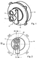
- FIG. 2 shows a plan view of the housing cover 16 and it can be seen through the inlet 12 and outlet 14 displacement chambers 20.
- FIG. 3 shows the rotor pump 10 in side view and the FIG. 4 in longitudinal section with removed housing pot 18th
- the displacement chambers 20 between an outer ring 22 and an inner ring 24 are formed.
- the outer ring 22 is internally toothed and has in the illustrated embodiment a total of six inwardly projecting teeth 26, between which tooth gaps 36 are located.
- the inner ring 24 is externally toothed and has a total of five outwardly facing teeth 28; which engage in the tooth gaps 36.
- the teeth 26 and 28 mesh and thereby form the Displacement spaces 20.
- the outer ring 22 and the inner ring 24 are aligned coaxially with each other, whereas their axes 30 and 32 have a distance 34 (eccentricity) to each other.
- the outer ring 22 forms the rotor 38 of a hollow shaft motor 40 and is rotatably mounted in a stator 42.
- This stator 42 has longitudinally extending and radially outwardly open receptacles 44 for (not shown) coils, whereas the rotor 38 forming outer ring 22 recesses 46 for magnets 48 (FIGS. FIG. 4 ) having.
- the recesses 46 of the illustrated embodiment are designed as depressions, so that a magnet 48 can be used from each side.
- the cross-section of the recesses 46 is substantially lenticular with a first radially outer peripheral surface 50 curved about the axis 30 and a second radially inner peripheral surface 52 following the profile of the tooth 26.
- FIG. 5 It is also clearly seen that rotation of the outer ring 22 causes rotation of the inner ring 24 about its axis 32, so that the teeth 26 and 28 mesh, thereby changing the size of the displacement spaces 20.
- Such a rotor pump 10 is not only simple, but also has a low weight and is easy to install and also has a larger flow at the same speed.
- the radial dimensions due to the integration of the magnets 48 in the outer ring 22 are low.
- the housing of the rotor pump 10 that is, the housing cover 16 and the housing pot 18, is penetrated by no components, and therefore no leaks are to be feared.
Landscapes
- Engineering & Computer Science (AREA)
- Mechanical Engineering (AREA)
- General Engineering & Computer Science (AREA)
- Rotary Pumps (AREA)
- Details And Applications Of Rotary Liquid Pumps (AREA)
Description
- Die Erfindung betrifft eine Rotorpumpe mit den Merkmalen des Oberbegriffs des Anspruchs 1.
- Es ist allgemein bekannt, dass mittels Rotorpumpen Fluide gefördert und Gase auch komprimiert werden können. Hierfür wälzt sich in einem innenverzahnten Außenring ein außenverzahnter Innenring ab, wobei der Innenring exzentrisch zum Außenring steht und mittels eines geeigneten Antriebs angetrieben wird. Weist der Innenring z.B. fünf Zähne auf, dann wälzen diese sich zwischen sechs Zähnen des Außenrings ab. Pro Umdrehung des Innenrings wird das Fluid in fünf Arbeitskammern angesaugt und aus diesen dann verdrängt.
- Aus der
DE 299 13 367 U1 ist eine Innenzahnradpumpe dieser Art bekannt, bei der der Außenring mittels eines Hohlwellenmotors angetrieben wird. Um den Außenring ist der Permanentmagnete tragende Rotor des Hohlwellenmotors angeordnet, wobei der Außenring und der Rotor in geeigneter Weise miteinander verbunden sind, so dass der Rotor den Außenring antreiben kann. Als nachteilig wird angesehen, dass eine derartige Innenzahnradpumpe in radialer Richtung große Abmessungen besitzt und dass eine Vielzahl von Teilen benötigt und montiert werden müssen. - Aus der
EP 1 803 938 A1 ist eine Rotorpumpe bekannt, bei der der Rotor des Antriebs mit dem Außenring gekoppelt ist. Antriebsmotor und Außenring stellen also zwei Bauteile dar, die miteinander verbunden werden müssen. - Die
JP 2 027 181 A - Der Erfindung liegt die Aufgabe zugrunde, eine Rotorpumpe bereitzustellen, welche bei gleicher Förderleistung kleinere Abmessungen besitzt und die weniger Bauteile aufweist.
- Diese Aufgabe wird mit einer Rotorpumpe gelöst, die die Merkmale des Anspruchs 1 aufweist.
- Die Integration des Rotors des Hohlwellenmotors in den Außenrings hat den wesentlichen Vorteil, dass ein Bauteil eingespart wird und dass gleichzeitig die radiale Abmessung reduziert werden kann. Neben der Einsparung von Bauteilen ist eine derartige Rotorpumpe auch leichter. Außerdem wird die Montage erleichtert, da kein Rotor mit dem Außenring verbunden werden muss. Der Innenring läuft lose um eine Achse mit. Von Vorteil ist, dass relativ große Rotations- oder Tangentialkräfte übertragen werden können, und es besteht keine die Gefahr, dass Vibrationen oder extreme Temperaturschwankungen ein Lösen des Rotors vom Außenring bewirken.
- Dabei sind zwischen den Zahnlücken oder in den Zähnen des Außenrings die Magnete für den Hohlwellenmotor angeordnet. Auch hierdurch wird die Baugröße vermindert, da der Platz innerhalb der Zähne dazu genutzt wird, die Magnete für den Hohlwellenmotor aufzunehmen. Dabei können die Magnete spezielle, an die Zahnform angepasste Formen annehmen.
- Der Außenring weist zur Aufnahme der Magnete Ausnehmungen auf, die von Durchbrüchen oder Einsenkungen gebildet werden. Von den Durchbrüche können relativ große Magnete aufgenommen werden, wohingegen in die Einsenkungen von beiden Seiten Magnete eingelegt werden können.
- Um den vorhandenen Raum zwischen den Zahnlücken optimal ausnutzen zu können, weisen die Ausnehmungen erfindungsgemäß einen im Wesentlichen linsenförmigen Querschnitt auf. Die Querschnittsform der Magnete sind entsprechend angepasst.
- Optimale Antriebskräfte werden dadurch erzeugt, dass die Teilung des Stators gleich ist, wie die Teilung des Außenringes, oder einem ganzzahligen vielfachen der Teilung des Außenringes entspricht.
- Eine einfache Variante sieht vor, dass der Außenring aus Aluminium oder Kunststoff besteht. Hierdurch wird das Gewicht der Rotorpumpe weiter reduziert und ein derartiger Rotor kann preiswert hergestellt werden.
- Weitere Merkmale, Vorteile und Einzelheiten der Erfindung ergeben sich aus den Unteransprüchen sowie der nachfolgenden Beschreibung, in der unter Bezugnahme auf die Zeichnung ein besonders bevorzugtes Ausführungsbeispiel im Einzelnen beschrieben ist. Dabei können die in der Zeichnung dargestellten sowie in der Beschreibung und in den Ansprüchen erwähnten Merkmale jeweils einzeln für sich oder in beliebiger Kombination erfindungswesentlich sein.
- In der Zeichnung zeigen:
- Figur 1
- eine perspektivische Darstellung der erfindungsgemäßen Rotorpumpe;
- Figur 2
- eine Draufsicht auf die Rotorpumpe;
- Figur 3
- eine Seitenansicht der Rotorpumpe in Richtung des Pfeils III gemäß
Figur 2 ; - Figur 4
- einen Schnitt IV-IV gemäß
Figur 2 ; und - Figur 5
- einen Schnitt V-V gemäß
Figur 3 . - In der
Figur 1 ist mit dem Bezugszeichen 10 eine Rotorpumpe dargestellt, mit welcher zum Beispiel Flüssigkeit, insbesondere Öl für einen Motor, wie Verbrennungsmotor, oder Harnstoff für ein Abgasreinigungssystem, gefördert wird. Hierfür weist die Rotorpumpe 10 einen Einlass 12 und einen Auslass 14 auf. Der Einlass 12 und der Auslass 14 sind in einem Gehäusedeckel 16 vorgesehen, welcher an einem Gehäusetopf 18 angeflanscht ist. Dabei wechseln der Einlass 12 und der Auslass 14 bei einem Wechsel der Drehrichtung. Deutlich erkennbar ist, dass die Rotorpumpe 10 in sich abgeschlossen und lediglich über den Einlass 12 und den Auslass 14 nach außen offen ist. In die Rotorpumpe 10 führt keine Antriebswelle oder dergleichen hinein, so dass sich Abdichtungen hierfür erübrigen. Eine derartige Rotorpumpe 10 erfüllt hohe Dichtigkeitsansprüche. - Die
Figur 2 zeigt eine Draufsicht auf den Gehäusedeckel 16 und es sind durch den Einlass 12 und Auslass 14 Verdrängungsräume 20 erkennbar. DieFigur 3 zeigt die Rotorpumpe 10 in Seitenansicht und dieFigur 4 im Längsschnitt mit abgenommenem Gehäusetopf 18. - Wie auch aus dem Querschnitt gemäß der
Figur 5 ersichtlich, werden die Verdrängungsräume 20 zwischen einem Außenring 22 und einem Innenring 24 gebildet. Dabei ist der Außenring 22 innenverzahnt und weist beim dargestellten Ausführungsbeispiel insgesamt sechs nach innen ragende Zähne 26 auf, zwischen denen sich Zahnlücken 36 befinden. Der Innenring 24 ist außenverzahnt und weist insgesamt fünf nach außen weisende Zähne 28 auf; die in die Zahnlücken 36 greifen. Die Zähne 26 und 28 kämmen und bilden dabei die Verdrängungsräume 20. Außerdem sind der Außenring 22 und der Innenring 24 koaxial zueinander ausgerichtet, wohingegen ihre Achsen 30 und 32 einen Abstand 34 (Exzentrizität) zueinander aufweisen. - Der Außenring 22 bildet den Rotor 38 eines Hohlwellenmotors 40 und ist in einem Stator 42 drehbar gelagert. Dieser Stator 42 weist in Längsrichtung verlaufende und radial nach außen offene Aufnahmen 44 für (nicht dargestellte) Spulen auf, wohingegen der den Rotor 38 bildende Außenring 22 Ausnehmungen 46 für Magnete 48 (
Figur 4 ) aufweist. Dabei sind die Ausnehmungen 46 des dargestellten Ausführungsbeispiels als Einsenkungen ausgeführt, so dass von jeder Seite ein Magnet 48 eingesetzt werden kann. Der Querschnitt der Ausnehmungen 46 ist im Wesentlichen linsenförmig mit einer ersten, radial äußeren Umfangsfläche 50, die um die Achse 30 gekrümmt ist, und einer zweiten, radial inneren Umfangsfläche 52, die dem Profil des Zahns 26 folgt. - Aus
Figur 5 ist außerdem deutlich erkennbar, dass Eine Drehung des Außenrings 22 eine Drehung des Innenrings 24 um dessen Achse 32 bewirkt, so dass die Zähne 26 und 28 kämmen, wodurch die Größe der Verdrängungsräume 20 verändert wird. - Eine derartige Rotorpumpe 10 ist nicht nur einfach aufgebaut, sondern besitzt auch ein geringes Gewicht und ist mühelos montierbar und besitzt zudem ein größeres Fördervolumen bei gleicher Drehzahl. Außerdem sind die radialen Abmessungen aufgrund der Integration der Magnete 48 in den Außenring 22 gering. Ferner ist deutlich in
Figur 5 erkennbar, dass das Gehäuse der Rotorpumpe 10, d.h. deren Gehäusedeckel 16 und deren Gehäusetopf 18, von keinen Bauteilen durchsetzt wird, und daher keine Undichtigkeiten zu befürchten sind.
Claims (4)
- Rotorpumpe (10) mit einem innenverzahnten Außenring (22) und einem darin gelagerten und mit diesem kämmenden, außenverzahnten Innenring (24), wobei der Außenring (22) und der Innenring (24) achsparallel zueinander angeordnet sind und die Achse (30) des Außenrings (22) und die Achse (32) des Innenrings (24) einen Abstand (34) zueinander aufweisen, wobei der Außenring (22) mittels eines Hohlwellenmotors (40) mit einem Wicklungen tragenden Stator (42) und einem darin drehbar gelagerten Rotor (38) angetrieben wird, und wobei der Außenring (22) den Rotor (38) des Hohlwellenmotors (40) bildet, wobei zwischen den Zahnlücken (36) des Außenrings (22) Magnete (48) angeordnet sind und der Außenring (22) zur Aufnahme der Magnete (48) Ausnehmungen (46) aufweist, die von Durchbrüchen oder Einsenkungen gebildet werden, dadurch gekennzeichnet, dass die Ausnehmungen (46) einen im Wesentlichen linsenförmigen Querschnitt aufweisen.
- Rotorpumpe nach Anspruch 1, dadurch gekennzeichnet, dass die Teilung des Stators (42) gleich ist, wie die Teilung des Außenringes (22), oder einem ganzzahligen vielfachen der Teilung des Außenringes (22) entspricht.
- Rotorpumpe nach einem der vorhergehenden Ansprüche,
dadurch gekennzeichnet, dass der Außenring (22) aus Aluminium oder Kunststoff besteht. - Rotorpumpe nach einem der vorhergehenden Ansprüche,
dadurch gekennzeichnet, dass alle Bauteile innerhalb oder an der Innenseite des Gehäuses (16, 18) der Rotorpumpe (10) gelagert sind und das Gehäuse (16, 18) von Bauteilen nicht durchsetzt wird.
Applications Claiming Priority (2)
| Application Number | Priority Date | Filing Date | Title |
|---|---|---|---|
| DE102007035239A DE102007035239A1 (de) | 2007-07-25 | 2007-07-25 | Rotorpumpe |
| PCT/EP2008/005415 WO2009012872A1 (de) | 2007-07-25 | 2008-07-03 | Integrierte innenzahnradpumpeneinheit mit elektrischem motor |
Publications (2)
| Publication Number | Publication Date |
|---|---|
| EP2122174A1 EP2122174A1 (de) | 2009-11-25 |
| EP2122174B1 true EP2122174B1 (de) | 2012-09-05 |
Family
ID=39790354
Family Applications (1)
| Application Number | Title | Priority Date | Filing Date |
|---|---|---|---|
| EP08773826A Not-in-force EP2122174B1 (de) | 2007-07-25 | 2008-07-03 | Integrierte innenzahnradpumpeneinheit mit elektrischem motor |
Country Status (5)
| Country | Link |
|---|---|
| US (1) | US8113794B2 (de) |
| EP (1) | EP2122174B1 (de) |
| CN (1) | CN101711313A (de) |
| DE (1) | DE102007035239A1 (de) |
| WO (1) | WO2009012872A1 (de) |
Families Citing this family (15)
| Publication number | Priority date | Publication date | Assignee | Title |
|---|---|---|---|---|
| US8376720B2 (en) * | 2010-03-05 | 2013-02-19 | GM Global Technology Operations LLC | Outer ring driven gerotor pump |
| DE102010029338A1 (de) * | 2010-05-27 | 2011-12-01 | Robert Bosch Gmbh | Innenzahnradpumpe |
| US8840385B2 (en) | 2011-03-03 | 2014-09-23 | Ti Group Automotive Systems, L.L.C. | Positive displacement fluid pump |
| DE102011082705A1 (de) * | 2011-09-14 | 2013-03-14 | Robert Bosch Gmbh | Pumpe, insbesondere Ölpumpe für eine Brennkraftmaschine |
| KR101326838B1 (ko) * | 2011-11-02 | 2013-11-11 | 현대자동차주식회사 | 요소수 펌프 구조 |
| WO2013127626A2 (de) * | 2012-02-27 | 2013-09-06 | Ixetic Bad Homburg Gmbh | Pumpenanordnung |
| JP5771560B2 (ja) * | 2012-05-30 | 2015-09-02 | 日立アプライアンス株式会社 | ギヤポンプ及びこれを備えた冷蔵庫 |
| US10590935B2 (en) * | 2012-10-29 | 2020-03-17 | Pierburg Pump Technology Gmbh | Automotive electric liquid pump |
| JP5952723B2 (ja) * | 2012-11-30 | 2016-07-13 | 株式会社日本自動車部品総合研究所 | 回転式ポンプおよびそれを備えたブレーキ装置 |
| CN103967780B (zh) * | 2014-04-11 | 2016-08-17 | 西安交通大学 | 一种开关磁通电机驱动的双联三齿轮内啮合复合电机泵 |
| US9724787B2 (en) * | 2014-08-07 | 2017-08-08 | Illinois Tool Works Inc. | System and method of monitoring a welding environment |
| DE102015207748A1 (de) * | 2015-04-28 | 2016-11-03 | Gkn Sinter Metals Engineering Gmbh | Fluidpumpe |
| IT201600129613A1 (it) * | 2016-12-21 | 2018-06-21 | Bosch Gmbh Robert | Pompa elettrica a ingranaggi |
| CN111779673B (zh) * | 2020-07-03 | 2021-12-10 | 浙江凯斯特动力科技有限公司 | 一种电机同轴内啮合齿轮泵 |
| CN115183046A (zh) * | 2022-09-13 | 2022-10-14 | 浙江大学高端装备研究院 | 一种紧凑型电液驱动执行器 |
Family Cites Families (16)
| Publication number | Priority date | Publication date | Assignee | Title |
|---|---|---|---|---|
| US19661A (en) * | 1858-03-16 | Metallic sash | ||
| JPS6211348Y2 (de) * | 1981-06-16 | 1987-03-17 | ||
| JPS6062850A (ja) * | 1983-09-16 | 1985-04-11 | Teijin Seiki Co Ltd | ギヤドモ−タ |
| JPH01182585A (ja) * | 1988-01-13 | 1989-07-20 | Komatsu Ltd | プラスチック製ギヤポンプ |
| JP2819024B2 (ja) | 1988-07-14 | 1998-10-30 | 株式会社タツノ・メカトロニクス | 超電導ロータリーポンプ |
| JP2924263B2 (ja) * | 1991-04-15 | 1999-07-26 | 住友電気工業株式会社 | 高強度アルミニウム合金製ポンプロータ |
| USH1966H1 (en) * | 1997-08-28 | 2001-06-05 | The United States Of America As Represented By The Secretary Of The Navy | Integrated motor/gear pump |
| JPH11210642A (ja) * | 1998-01-20 | 1999-08-03 | Zexel:Kk | 内接ギアポンプ |
| DE29810548U1 (de) * | 1998-06-16 | 1998-12-17 | Joma-Polytec GmbH, 72411 Bodelshausen | Zahnrad für eine Zahnradpumpe |
| US7186101B2 (en) * | 1998-07-31 | 2007-03-06 | The Texas A&M University System | Gerotor apparatus for a quasi-isothermal Brayton cycle Engine |
| DE29913367U1 (de) | 1999-07-30 | 1999-12-09 | Pumpenfabrik Ernst Scherzinger GmbH & Co. KG, 78120 Furtwangen | Innen-Zahnradpumpe, deren Hohlrad das Innere eines Rotors eines Elektromotors ist |
| JP2003164082A (ja) * | 2001-11-22 | 2003-06-06 | Hitachi Metals Ltd | フェライト磁石および回転機、フェライト磁石の製造方法 |
| DE10248933C1 (de) * | 2002-10-19 | 2003-12-11 | Pumpenfabrik Ernst Scherzinger | Innen-Zahnradpumpe mit einem verzahnten Hohlrad und einem damit kämmenden Laufrad |
| JP4237731B2 (ja) * | 2005-05-31 | 2009-03-11 | 株式会社日立製作所 | モータ一体型内接歯車式ポンプ及びその製造方法並びに電子機器 |
| EP1803938A1 (de) | 2005-12-27 | 2007-07-04 | Techspace Aero S.A. | Hochintegrierte Pumpeneinheit mit elektrischem Motor |
| DE102006007554A1 (de) * | 2006-02-16 | 2007-08-23 | Hydraulik-Ring Gmbh | Förderpumpe, insbesondere für Harnstoffwasserlösung als Abgasnachbehandlungsmedium |
-
2007
- 2007-07-25 DE DE102007035239A patent/DE102007035239A1/de not_active Withdrawn
-
2008
- 2008-07-03 WO PCT/EP2008/005415 patent/WO2009012872A1/de not_active Ceased
- 2008-07-03 EP EP08773826A patent/EP2122174B1/de not_active Not-in-force
- 2008-07-03 CN CN200880020585A patent/CN101711313A/zh active Pending
-
2010
- 2010-01-06 US US12/652,811 patent/US8113794B2/en active Active
Also Published As
| Publication number | Publication date |
|---|---|
| US20100111722A1 (en) | 2010-05-06 |
| EP2122174A1 (de) | 2009-11-25 |
| WO2009012872A1 (de) | 2009-01-29 |
| CN101711313A (zh) | 2010-05-19 |
| DE102007035239A1 (de) | 2009-01-29 |
| US8113794B2 (en) | 2012-02-14 |
Similar Documents
| Publication | Publication Date | Title |
|---|---|---|
| EP2122174A1 (de) | Integrierte innenzahnradpumpeneinheit mit elektrischem motor | |
| DE69515564T2 (de) | Seitenkanal-Pumpe mit geräuschdämpfender Vorrichtung | |
| DE10015139A1 (de) | Motorpumpenaggregat | |
| DE102005018956A1 (de) | Vorrichtung zur Nockenwellenverstellung einer Brennkraftmaschine | |
| EP3507496B1 (de) | Trockenverdichtende vakuumpumpe | |
| DE2258135A1 (de) | Mehrgaengiges rotor-schraubentriebwerk | |
| EP1252444B1 (de) | Antrieb einer schraubenspindelpumpe | |
| DE102019204189A1 (de) | Getriebe und Antriebsstrang für ein Kraftfahrzeug | |
| DE10304121A1 (de) | Motorpumpenaggregat | |
| EP1536139B1 (de) | Pumpenaggregat mit einer Zahnradpumpe und einem Elektromotor | |
| DE1934467A1 (de) | Rotor-Statorradsatz fuer Arbeitsmaschinen | |
| EP3827170B1 (de) | Fluidfördereinrichtung | |
| DE102009006521A1 (de) | Drehkolbenmaschine | |
| EP2556256B1 (de) | Drehkolbenpumpe und verfahren zum betreiben einer drehkolbenpumpe | |
| CH664193A5 (de) | Abgasbetriebener rotationskolbenlader. | |
| DE19940730A1 (de) | Außenzahnradpumpe | |
| DE10349752B4 (de) | Motorpumpenaggregat | |
| DE68901750T2 (de) | Druckschmiervorrichtung fuer getriebesysteme fuer motorfahrzeuge mit querliegendem getriebegehaeuse. | |
| EP2625427B1 (de) | Strömungsgetriebe | |
| DE102009037199A1 (de) | Hydraulische Zahnradmaschine | |
| EP3441613B1 (de) | Hydrostatische zahnrad-kreiskolbenmaschine | |
| DE102022206319A1 (de) | Elektrische Zahnradpumpe für ein Kraftfahrzeug, insbesondere Gerotor-Pumpe sowie Set aus mehreren Zahnradpumpen | |
| DE202014006761U1 (de) | Hydrostatische Kreiskolbenmaschine nach dem Orbitprinzip | |
| DE102012206797A1 (de) | Drehkolbenmaschine, die als Pumpe, Verdichter oder Motor für ein Fluid wirkt | |
| DE102021209030A1 (de) | Pumpe mit Pulsationskompensation |
Legal Events
| Date | Code | Title | Description |
|---|---|---|---|
| PUAI | Public reference made under article 153(3) epc to a published international application that has entered the european phase |
Free format text: ORIGINAL CODE: 0009012 |
|
| 17P | Request for examination filed |
Effective date: 20090910 |
|
| AK | Designated contracting states |
Kind code of ref document: A1 Designated state(s): AT BE BG CH CY CZ DE DK EE ES FI FR GB GR HR HU IE IS IT LI LT LU LV MC MT NL NO PL PT RO SE SI SK TR |
|
| RAP1 | Party data changed (applicant data changed or rights of an application transferred) |
Owner name: JOMA-POLYTEC GMBH |
|
| DAX | Request for extension of the european patent (deleted) | ||
| 17Q | First examination report despatched |
Effective date: 20111213 |
|
| GRAP | Despatch of communication of intention to grant a patent |
Free format text: ORIGINAL CODE: EPIDOSNIGR1 |
|
| GRAS | Grant fee paid |
Free format text: ORIGINAL CODE: EPIDOSNIGR3 |
|
| GRAA | (expected) grant |
Free format text: ORIGINAL CODE: 0009210 |
|
| AK | Designated contracting states |
Kind code of ref document: B1 Designated state(s): AT BE BG CH CY CZ DE DK EE ES FI FR GB GR HR HU IE IS IT LI LT LU LV MC MT NL NO PL PT RO SE SI SK TR |
|
| REG | Reference to a national code |
Ref country code: GB Ref legal event code: FG4D Free format text: NOT ENGLISH |
|
| REG | Reference to a national code |
Ref country code: CH Ref legal event code: EP |
|
| REG | Reference to a national code |
Ref country code: AT Ref legal event code: REF Ref document number: 574256 Country of ref document: AT Kind code of ref document: T Effective date: 20120915 |
|
| REG | Reference to a national code |
Ref country code: IE Ref legal event code: FG4D Free format text: LANGUAGE OF EP DOCUMENT: GERMAN |
|
| REG | Reference to a national code |
Ref country code: DE Ref legal event code: R096 Ref document number: 502008008112 Country of ref document: DE Effective date: 20121031 |
|
| REG | Reference to a national code |
Ref country code: NL Ref legal event code: VDEP Effective date: 20120905 |
|
| PG25 | Lapsed in a contracting state [announced via postgrant information from national office to epo] |
Ref country code: HR Free format text: LAPSE BECAUSE OF FAILURE TO SUBMIT A TRANSLATION OF THE DESCRIPTION OR TO PAY THE FEE WITHIN THE PRESCRIBED TIME-LIMIT Effective date: 20120905 Ref country code: NO Free format text: LAPSE BECAUSE OF FAILURE TO SUBMIT A TRANSLATION OF THE DESCRIPTION OR TO PAY THE FEE WITHIN THE PRESCRIBED TIME-LIMIT Effective date: 20121205 Ref country code: CY Free format text: LAPSE BECAUSE OF FAILURE TO SUBMIT A TRANSLATION OF THE DESCRIPTION OR TO PAY THE FEE WITHIN THE PRESCRIBED TIME-LIMIT Effective date: 20120905 Ref country code: FI Free format text: LAPSE BECAUSE OF FAILURE TO SUBMIT A TRANSLATION OF THE DESCRIPTION OR TO PAY THE FEE WITHIN THE PRESCRIBED TIME-LIMIT Effective date: 20120905 Ref country code: LT Free format text: LAPSE BECAUSE OF FAILURE TO SUBMIT A TRANSLATION OF THE DESCRIPTION OR TO PAY THE FEE WITHIN THE PRESCRIBED TIME-LIMIT Effective date: 20120905 |
|
| REG | Reference to a national code |
Ref country code: LT Ref legal event code: MG4D Effective date: 20120905 |
|
| PG25 | Lapsed in a contracting state [announced via postgrant information from national office to epo] |
Ref country code: SE Free format text: LAPSE BECAUSE OF FAILURE TO SUBMIT A TRANSLATION OF THE DESCRIPTION OR TO PAY THE FEE WITHIN THE PRESCRIBED TIME-LIMIT Effective date: 20120905 Ref country code: SI Free format text: LAPSE BECAUSE OF FAILURE TO SUBMIT A TRANSLATION OF THE DESCRIPTION OR TO PAY THE FEE WITHIN THE PRESCRIBED TIME-LIMIT Effective date: 20120905 Ref country code: GR Free format text: LAPSE BECAUSE OF FAILURE TO SUBMIT A TRANSLATION OF THE DESCRIPTION OR TO PAY THE FEE WITHIN THE PRESCRIBED TIME-LIMIT Effective date: 20121206 Ref country code: LV Free format text: LAPSE BECAUSE OF FAILURE TO SUBMIT A TRANSLATION OF THE DESCRIPTION OR TO PAY THE FEE WITHIN THE PRESCRIBED TIME-LIMIT Effective date: 20120905 |
|
| PG25 | Lapsed in a contracting state [announced via postgrant information from national office to epo] |
Ref country code: IS Free format text: LAPSE BECAUSE OF FAILURE TO SUBMIT A TRANSLATION OF THE DESCRIPTION OR TO PAY THE FEE WITHIN THE PRESCRIBED TIME-LIMIT Effective date: 20130105 Ref country code: RO Free format text: LAPSE BECAUSE OF FAILURE TO SUBMIT A TRANSLATION OF THE DESCRIPTION OR TO PAY THE FEE WITHIN THE PRESCRIBED TIME-LIMIT Effective date: 20120905 Ref country code: NL Free format text: LAPSE BECAUSE OF FAILURE TO SUBMIT A TRANSLATION OF THE DESCRIPTION OR TO PAY THE FEE WITHIN THE PRESCRIBED TIME-LIMIT Effective date: 20120905 Ref country code: CZ Free format text: LAPSE BECAUSE OF FAILURE TO SUBMIT A TRANSLATION OF THE DESCRIPTION OR TO PAY THE FEE WITHIN THE PRESCRIBED TIME-LIMIT Effective date: 20120905 Ref country code: EE Free format text: LAPSE BECAUSE OF FAILURE TO SUBMIT A TRANSLATION OF THE DESCRIPTION OR TO PAY THE FEE WITHIN THE PRESCRIBED TIME-LIMIT Effective date: 20120905 |
|
| PG25 | Lapsed in a contracting state [announced via postgrant information from national office to epo] |
Ref country code: SK Free format text: LAPSE BECAUSE OF FAILURE TO SUBMIT A TRANSLATION OF THE DESCRIPTION OR TO PAY THE FEE WITHIN THE PRESCRIBED TIME-LIMIT Effective date: 20120905 Ref country code: PT Free format text: LAPSE BECAUSE OF FAILURE TO SUBMIT A TRANSLATION OF THE DESCRIPTION OR TO PAY THE FEE WITHIN THE PRESCRIBED TIME-LIMIT Effective date: 20130107 Ref country code: PL Free format text: LAPSE BECAUSE OF FAILURE TO SUBMIT A TRANSLATION OF THE DESCRIPTION OR TO PAY THE FEE WITHIN THE PRESCRIBED TIME-LIMIT Effective date: 20120905 |
|
| PLBE | No opposition filed within time limit |
Free format text: ORIGINAL CODE: 0009261 |
|
| STAA | Information on the status of an ep patent application or granted ep patent |
Free format text: STATUS: NO OPPOSITION FILED WITHIN TIME LIMIT |
|
| PG25 | Lapsed in a contracting state [announced via postgrant information from national office to epo] |
Ref country code: BG Free format text: LAPSE BECAUSE OF FAILURE TO SUBMIT A TRANSLATION OF THE DESCRIPTION OR TO PAY THE FEE WITHIN THE PRESCRIBED TIME-LIMIT Effective date: 20121205 Ref country code: DK Free format text: LAPSE BECAUSE OF FAILURE TO SUBMIT A TRANSLATION OF THE DESCRIPTION OR TO PAY THE FEE WITHIN THE PRESCRIBED TIME-LIMIT Effective date: 20120905 |
|
| 26N | No opposition filed |
Effective date: 20130606 |
|
| REG | Reference to a national code |
Ref country code: DE Ref legal event code: R097 Ref document number: 502008008112 Country of ref document: DE Effective date: 20130606 |
|
| PG25 | Lapsed in a contracting state [announced via postgrant information from national office to epo] |
Ref country code: ES Free format text: LAPSE BECAUSE OF FAILURE TO SUBMIT A TRANSLATION OF THE DESCRIPTION OR TO PAY THE FEE WITHIN THE PRESCRIBED TIME-LIMIT Effective date: 20121216 |
|
| PGFP | Annual fee paid to national office [announced via postgrant information from national office to epo] |
Ref country code: IT Payment date: 20130729 Year of fee payment: 6 |
|
| BERE | Be: lapsed |
Owner name: JOMA-POLYTEC G.M.B.H. Effective date: 20130731 |
|
| PG25 | Lapsed in a contracting state [announced via postgrant information from national office to epo] |
Ref country code: MC Free format text: LAPSE BECAUSE OF FAILURE TO SUBMIT A TRANSLATION OF THE DESCRIPTION OR TO PAY THE FEE WITHIN THE PRESCRIBED TIME-LIMIT Effective date: 20120905 |
|
| REG | Reference to a national code |
Ref country code: CH Ref legal event code: PL |
|
| GBPC | Gb: european patent ceased through non-payment of renewal fee |
Effective date: 20130703 |
|
| REG | Reference to a national code |
Ref country code: IE Ref legal event code: MM4A |
|
| PG25 | Lapsed in a contracting state [announced via postgrant information from national office to epo] |
Ref country code: LI Free format text: LAPSE BECAUSE OF NON-PAYMENT OF DUE FEES Effective date: 20130731 Ref country code: GB Free format text: LAPSE BECAUSE OF NON-PAYMENT OF DUE FEES Effective date: 20130703 Ref country code: CH Free format text: LAPSE BECAUSE OF NON-PAYMENT OF DUE FEES Effective date: 20130731 Ref country code: BE Free format text: LAPSE BECAUSE OF NON-PAYMENT OF DUE FEES Effective date: 20130731 |
|
| PG25 | Lapsed in a contracting state [announced via postgrant information from national office to epo] |
Ref country code: IE Free format text: LAPSE BECAUSE OF NON-PAYMENT OF DUE FEES Effective date: 20130703 |
|
| REG | Reference to a national code |
Ref country code: AT Ref legal event code: MM01 Ref document number: 574256 Country of ref document: AT Kind code of ref document: T Effective date: 20130703 |
|
| PG25 | Lapsed in a contracting state [announced via postgrant information from national office to epo] |
Ref country code: AT Free format text: LAPSE BECAUSE OF NON-PAYMENT OF DUE FEES Effective date: 20130703 |
|
| PGFP | Annual fee paid to national office [announced via postgrant information from national office to epo] |
Ref country code: FR Payment date: 20140724 Year of fee payment: 7 |
|
| PG25 | Lapsed in a contracting state [announced via postgrant information from national office to epo] |
Ref country code: IT Free format text: LAPSE BECAUSE OF NON-PAYMENT OF DUE FEES Effective date: 20140703 |
|
| PG25 | Lapsed in a contracting state [announced via postgrant information from national office to epo] |
Ref country code: TR Free format text: LAPSE BECAUSE OF FAILURE TO SUBMIT A TRANSLATION OF THE DESCRIPTION OR TO PAY THE FEE WITHIN THE PRESCRIBED TIME-LIMIT Effective date: 20120905 Ref country code: MT Free format text: LAPSE BECAUSE OF FAILURE TO SUBMIT A TRANSLATION OF THE DESCRIPTION OR TO PAY THE FEE WITHIN THE PRESCRIBED TIME-LIMIT Effective date: 20120905 |
|
| PG25 | Lapsed in a contracting state [announced via postgrant information from national office to epo] |
Ref country code: HU Free format text: LAPSE BECAUSE OF FAILURE TO SUBMIT A TRANSLATION OF THE DESCRIPTION OR TO PAY THE FEE WITHIN THE PRESCRIBED TIME-LIMIT; INVALID AB INITIO Effective date: 20080703 Ref country code: LU Free format text: LAPSE BECAUSE OF NON-PAYMENT OF DUE FEES Effective date: 20130703 |
|
| REG | Reference to a national code |
Ref country code: FR Ref legal event code: ST Effective date: 20160331 |
|
| PG25 | Lapsed in a contracting state [announced via postgrant information from national office to epo] |
Ref country code: FR Free format text: LAPSE BECAUSE OF NON-PAYMENT OF DUE FEES Effective date: 20150731 |
|
| P01 | Opt-out of the competence of the unified patent court (upc) registered |
Effective date: 20230621 |
|
| PGFP | Annual fee paid to national office [announced via postgrant information from national office to epo] |
Ref country code: DE Payment date: 20240920 Year of fee payment: 17 |
|
| REG | Reference to a national code |
Ref country code: DE Ref legal event code: R119 Ref document number: 502008008112 Country of ref document: DE |
|
| PG25 | Lapsed in a contracting state [announced via postgrant information from national office to epo] |
Ref country code: DE Free format text: LAPSE BECAUSE OF NON-PAYMENT OF DUE FEES Effective date: 20260203 |