EP2119392B1 - Device, system and method for magnetically maneuvering an in vivo device - Google Patents
Device, system and method for magnetically maneuvering an in vivo device Download PDFInfo
- Publication number
- EP2119392B1 EP2119392B1 EP09160289.6A EP09160289A EP2119392B1 EP 2119392 B1 EP2119392 B1 EP 2119392B1 EP 09160289 A EP09160289 A EP 09160289A EP 2119392 B1 EP2119392 B1 EP 2119392B1
- Authority
- EP
- European Patent Office
- Prior art keywords
- vivo
- magnetic field
- imaging
- capsule
- transceiver
- Prior art date
- Legal status (The legal status is an assumption and is not a legal conclusion. Google has not performed a legal analysis and makes no representation as to the accuracy of the status listed.)
- Active
Links
- 238000001727 in vivo Methods 0.000 title description 46
- 238000000034 method Methods 0.000 title description 24
- 238000003384 imaging method Methods 0.000 claims description 30
- 238000011503 in vivo imaging Methods 0.000 claims description 14
- 239000002775 capsule Substances 0.000 description 32
- 230000033001 locomotion Effects 0.000 description 18
- 210000001519 tissue Anatomy 0.000 description 14
- 238000012545 processing Methods 0.000 description 13
- 230000003287 optical effect Effects 0.000 description 12
- 210000001035 gastrointestinal tract Anatomy 0.000 description 9
- 210000002784 stomach Anatomy 0.000 description 8
- 238000005286 illumination Methods 0.000 description 7
- 230000005484 gravity Effects 0.000 description 6
- 210000003238 esophagus Anatomy 0.000 description 5
- 210000000056 organ Anatomy 0.000 description 5
- 230000005540 biological transmission Effects 0.000 description 4
- 238000001574 biopsy Methods 0.000 description 4
- 230000008569 process Effects 0.000 description 4
- 238000004458 analytical method Methods 0.000 description 3
- 239000000090 biomarker Substances 0.000 description 3
- 230000005672 electromagnetic field Effects 0.000 description 3
- 230000006870 function Effects 0.000 description 3
- 230000036541 health Effects 0.000 description 3
- 241001465754 Metazoa Species 0.000 description 2
- 210000004204 blood vessel Anatomy 0.000 description 2
- 238000007405 data analysis Methods 0.000 description 2
- 238000001514 detection method Methods 0.000 description 2
- 210000000981 epithelium Anatomy 0.000 description 2
- 230000002496 gastric effect Effects 0.000 description 2
- 238000010191 image analysis Methods 0.000 description 2
- 210000005000 reproductive tract Anatomy 0.000 description 2
- 238000005096 rolling process Methods 0.000 description 2
- NDVLTYZPCACLMA-UHFFFAOYSA-N silver oxide Chemical compound [O-2].[Ag+].[Ag+] NDVLTYZPCACLMA-UHFFFAOYSA-N 0.000 description 2
- 235000017060 Arachis glabrata Nutrition 0.000 description 1
- 241001553178 Arachis glabrata Species 0.000 description 1
- 235000010777 Arachis hypogaea Nutrition 0.000 description 1
- 235000018262 Arachis monticola Nutrition 0.000 description 1
- WHXSMMKQMYFTQS-UHFFFAOYSA-N Lithium Chemical compound [Li] WHXSMMKQMYFTQS-UHFFFAOYSA-N 0.000 description 1
- 108010001267 Protein Subunits Proteins 0.000 description 1
- 208000027418 Wounds and injury Diseases 0.000 description 1
- 238000005299 abrasion Methods 0.000 description 1
- 230000004913 activation Effects 0.000 description 1
- 239000000654 additive Substances 0.000 description 1
- 230000000712 assembly Effects 0.000 description 1
- 238000000429 assembly Methods 0.000 description 1
- 230000008859 change Effects 0.000 description 1
- 210000001072 colon Anatomy 0.000 description 1
- 230000000295 complement effect Effects 0.000 description 1
- 239000002131 composite material Substances 0.000 description 1
- 150000001875 compounds Chemical group 0.000 description 1
- 230000006378 damage Effects 0.000 description 1
- 239000003814 drug Substances 0.000 description 1
- 229940079593 drug Drugs 0.000 description 1
- 230000002708 enhancing effect Effects 0.000 description 1
- 230000005284 excitation Effects 0.000 description 1
- 208000014674 injury Diseases 0.000 description 1
- 238000007689 inspection Methods 0.000 description 1
- 229910052744 lithium Inorganic materials 0.000 description 1
- 229910044991 metal oxide Inorganic materials 0.000 description 1
- 150000004706 metal oxides Chemical class 0.000 description 1
- 239000013307 optical fiber Substances 0.000 description 1
- 238000001139 pH measurement Methods 0.000 description 1
- 235000020232 peanut Nutrition 0.000 description 1
- 230000000737 periodic effect Effects 0.000 description 1
- 230000002093 peripheral effect Effects 0.000 description 1
- 230000008855 peristalsis Effects 0.000 description 1
- 238000012805 post-processing Methods 0.000 description 1
- 239000004065 semiconductor Substances 0.000 description 1
- 230000001953 sensory effect Effects 0.000 description 1
- 229910001923 silver oxide Inorganic materials 0.000 description 1
- 239000000126 substance Chemical group 0.000 description 1
- 230000001225 therapeutic effect Effects 0.000 description 1
- 210000001635 urinary tract Anatomy 0.000 description 1
- 210000001835 viscera Anatomy 0.000 description 1
Images
Classifications
-
- A—HUMAN NECESSITIES
- A61—MEDICAL OR VETERINARY SCIENCE; HYGIENE
- A61B—DIAGNOSIS; SURGERY; IDENTIFICATION
- A61B1/00—Instruments for performing medical examinations of the interior of cavities or tubes of the body by visual or photographical inspection, e.g. endoscopes; Illuminating arrangements therefor
- A61B1/04—Instruments for performing medical examinations of the interior of cavities or tubes of the body by visual or photographical inspection, e.g. endoscopes; Illuminating arrangements therefor combined with photographic or television appliances
- A61B1/041—Capsule endoscopes for imaging
-
- A—HUMAN NECESSITIES
- A61—MEDICAL OR VETERINARY SCIENCE; HYGIENE
- A61B—DIAGNOSIS; SURGERY; IDENTIFICATION
- A61B1/00—Instruments for performing medical examinations of the interior of cavities or tubes of the body by visual or photographical inspection, e.g. endoscopes; Illuminating arrangements therefor
- A61B1/00147—Holding or positioning arrangements
- A61B1/00158—Holding or positioning arrangements using magnetic field
-
- A—HUMAN NECESSITIES
- A61—MEDICAL OR VETERINARY SCIENCE; HYGIENE
- A61B—DIAGNOSIS; SURGERY; IDENTIFICATION
- A61B34/00—Computer-aided surgery; Manipulators or robots specially adapted for use in surgery
- A61B34/70—Manipulators specially adapted for use in surgery
-
- A—HUMAN NECESSITIES
- A61—MEDICAL OR VETERINARY SCIENCE; HYGIENE
- A61B—DIAGNOSIS; SURGERY; IDENTIFICATION
- A61B34/00—Computer-aided surgery; Manipulators or robots specially adapted for use in surgery
- A61B34/70—Manipulators specially adapted for use in surgery
- A61B34/72—Micromanipulators
-
- A—HUMAN NECESSITIES
- A61—MEDICAL OR VETERINARY SCIENCE; HYGIENE
- A61B—DIAGNOSIS; SURGERY; IDENTIFICATION
- A61B34/00—Computer-aided surgery; Manipulators or robots specially adapted for use in surgery
- A61B34/70—Manipulators specially adapted for use in surgery
- A61B34/73—Manipulators for magnetic surgery
-
- A—HUMAN NECESSITIES
- A61—MEDICAL OR VETERINARY SCIENCE; HYGIENE
- A61B—DIAGNOSIS; SURGERY; IDENTIFICATION
- A61B5/00—Measuring for diagnostic purposes; Identification of persons
- A61B5/06—Devices, other than using radiation, for detecting or locating foreign bodies ; determining position of probes within or on the body of the patient
- A61B5/065—Determining position of the probe employing exclusively positioning means located on or in the probe, e.g. using position sensors arranged on the probe
-
- A—HUMAN NECESSITIES
- A61—MEDICAL OR VETERINARY SCIENCE; HYGIENE
- A61B—DIAGNOSIS; SURGERY; IDENTIFICATION
- A61B5/00—Measuring for diagnostic purposes; Identification of persons
- A61B5/07—Endoradiosondes
- A61B5/073—Intestinal transmitters
-
- A—HUMAN NECESSITIES
- A61—MEDICAL OR VETERINARY SCIENCE; HYGIENE
- A61B—DIAGNOSIS; SURGERY; IDENTIFICATION
- A61B5/00—Measuring for diagnostic purposes; Identification of persons
- A61B5/145—Measuring characteristics of blood in vivo, e.g. gas concentration, pH value; Measuring characteristics of body fluids or tissues, e.g. interstitial fluid, cerebral tissue
- A61B5/14539—Measuring characteristics of blood in vivo, e.g. gas concentration, pH value; Measuring characteristics of body fluids or tissues, e.g. interstitial fluid, cerebral tissue for measuring pH
-
- A—HUMAN NECESSITIES
- A61—MEDICAL OR VETERINARY SCIENCE; HYGIENE
- A61B—DIAGNOSIS; SURGERY; IDENTIFICATION
- A61B1/00—Instruments for performing medical examinations of the interior of cavities or tubes of the body by visual or photographical inspection, e.g. endoscopes; Illuminating arrangements therefor
- A61B1/00002—Operational features of endoscopes
- A61B1/00025—Operational features of endoscopes characterised by power management
- A61B1/00036—Means for power saving, e.g. sleeping mode
-
- A—HUMAN NECESSITIES
- A61—MEDICAL OR VETERINARY SCIENCE; HYGIENE
- A61B—DIAGNOSIS; SURGERY; IDENTIFICATION
- A61B1/00—Instruments for performing medical examinations of the interior of cavities or tubes of the body by visual or photographical inspection, e.g. endoscopes; Illuminating arrangements therefor
- A61B1/273—Instruments for performing medical examinations of the interior of cavities or tubes of the body by visual or photographical inspection, e.g. endoscopes; Illuminating arrangements therefor for the upper alimentary canal, e.g. oesophagoscopes, gastroscopes
- A61B1/2736—Gastroscopes
-
- A—HUMAN NECESSITIES
- A61—MEDICAL OR VETERINARY SCIENCE; HYGIENE
- A61B—DIAGNOSIS; SURGERY; IDENTIFICATION
- A61B1/00—Instruments for performing medical examinations of the interior of cavities or tubes of the body by visual or photographical inspection, e.g. endoscopes; Illuminating arrangements therefor
- A61B1/31—Instruments for performing medical examinations of the interior of cavities or tubes of the body by visual or photographical inspection, e.g. endoscopes; Illuminating arrangements therefor for the rectum, e.g. proctoscopes, sigmoidoscopes, colonoscopes
Definitions
- the present invention relates to an in-vivo device and method such as for imaging an in-vivo lumen. More specifically, the present invention relates to a method and apparatus in an in-vivo system for magnetically positioning and maneuvering an in-vivo imaging device.
- Known devices may be helpful in providing in-vivo sensing, such as imaging or pH sensing.
- Autonomous in-vivo sensing devices such as swallowable or ingestible capsules or other devices, may move through a body lumen, sensing as they move along.
- the devices are typically autonomous in-vivo sensing device such as an imaging device and may include, for example, an imager for obtaining images from inside a body cavity or lumen, such as the gastrointestinal (GI) tract while the in-vivo imaging device passes through the GI lumen.
- the imager may, for example, be associated with an optical system, and optionally a transceiver and an antenna. Some of these devices use a wireless connection to transmit image data.
- Other devices, systems and methods for in-vivo sensing of passages or cavities within a body, and for sensing and gathering information are known in the art.
- Such devices may passively or actively progress through a body lumen, e.g., the gastrointestinal (GI) tract, for example, pushed along by natural peristalsis.
- GI gastrointestinal
- Magnetically controlling movement of an in vivo device has been described, for example in US Patent Number 4,278,077 in which there is described a current source that generats a magnetic field outside a patient's body.
- the magnetic field acts on a permanent magnets in a miniature camera device swallowed by the patient and thus moves the camera device in the stomach.
- US Patent Number 6,776,165 to Jin discloses a navigation system and navigatable capsules for remote-controlled imaging, biopsy and programmable drug release within the body of an animal.
- the components of the system comprise a capsule dimensioned and shaped to move within the body.
- An anisotropic magnetic component is mechanically coupled to the capsule to move or orient the body in relation to an applied magnetic field, and a magnetic field generating system external of the body generates a three dimensionally oriented magnetic field within the body to move or orient capsule.
- US Patent Number 7,182,089 to Ries discloses a magnetically navigable device with a magnet element that has a greater extent in one direction.
- the magnet element is arranged asymmetrically with respect to a central axis of the device, which points in the direction in which the magnet element extends.
- the magnetic element interacts with a gravitational force and a compensating magnetic force generated by external magnetic field gradients, which cause rotation of the magnetic element around the axis of the device to a to position counter to the gravitational force.
- Prior art methods typically enable a specific but fixed point of view to an in vivo imaging, not easily enabling widening and/or changing the viewing angle during the device's progress in the lumen. Additionally, prior art methods of moving a device in vivo typically cause the device to be pulled or dragged in the lumen, possibly causing patient discomfort and abrasion of the tissue lining.
- US 2003/0229268 discloses an encapsulated endoscope system that includes an encapsulated endoscope that rotates to develop a thrust, and an imaging unit and an image processing unit.
- the image processing unit produces an image that results from rotation of the image data, according to the rotational phase of the encapsulated endoscope.
- US 2006/0063974 discloses a guided capsule 3 that includes a magnet 16 to act on a rotating electromagnetic field, and that has a spiral projection portion 12 provided on the outer peripheral surface of the capsule in order to convert a rotational movement of the capsule, which is generated by the magnet 16 and a rotating electromagnetic field, into a thrust force.
- WO 2008/026549 discloses a capsule guiding system that includes an electrode pad (7), a head (3) for fixing/arranging the electrode pad (7), a magnetic field generation device (1) for moving an encapsulated endoscope (6), a position/direction calculation unit (12), and a control unit (13).
- An absolute position and/or absolute direction of the encapsulated endoscope (6) with respect to the magnetic field generation device (1) is obtained, and the control unit (13) controls the magnetic field generation device (1) according to the absolute position and/or the absolute direction of the encapsulated endoscope (6).
- Embodiments of the invention provide a system for controlling movement of an imaging device in vivo which do not suffer from the shortcomings of the prior art.
- an in vivo imaging system comprising:
- parameters of the rotating magnetic field can be controlled either automatically or manually. According to some embodiments controlling parameters of the rotating magnetic field based on input from the imaging device (such as image data or other data that may be collected by the device).
- the imaging device may be caused to halt at a point in the patient's esophagus, said point enabling the device a view of the patient's z-line; and causing the device to rotate around its longitudinal axis.
- the swallowable capsule may be produced by enclosing within a capsule shaped housing an imager and illumination elements, thereby producing an imaging capsule; calculating the center of mass of the imaging capsule; and positioning a magnetic component within or on the imaging capsule, such that the magnetic component position does not coincide with the center of mass.
- the swallowable capsule may alternatively be produced by enclosing within a device housing, said housing having at a viewing end a viewing window, a magnetic component, an imager and illumination elements, thereby producing an imaging device; and creating a center of mass of the device at an end of the device opposite the viewing end.
- Some embodiments of the present invention are directed to an in-vivo device that may be inserted into a body lumen, e.g., the gastro-intestinal (GI) tract, for example, from outside the body. Some embodiments are directed to a typically one time use or partially single use detection and/or analysis device. Some embodiments are directed to in-vivo sensing devices that may be passed through other body lumens, for example, through blood vessels, the reproductive tract, or the like.
- the in-vivo device may be, for example, a sensing device, an imaging device, a diagnostic device, a detection device, an analysis device, a therapeutic device, or a combination thereof.
- the in-vivo device may include an image sensor or an imager and/or other suitable components. Some embodiments of the present invention may be directed to other imaging devices, not necessarily in-vivo imaging.
- Controlling and positioning an in vivo imaging device may be useful in certain cases.
- the health care professional may want to closely examine the patient's esophagus, and spend extra time around the the border between the squamous lined epithelium of the esophagus and the columnar epithelium of the stomach (the Z-line), in order to make sure it is fully viewed from several directions by the imaging device.
- it may be useful to stop the device at a certain point in the esophagus, for example just before the Z-line, and twist or rotate it around its longitudinal axis in a circular manner in order to capture a complete view of the in vivo area.
- the images of the Z-line are captured from different directions.
- the health care professional may wish to inspect the patient's stomach, an organ which is typically much larger than the imaging device.
- a capsule When a capsule is moving independently with no external control, it may tumble arbitrarily around the stomach.
- the doctor would want to make sure that all of the stomach's tissue is examined, and that images covering the whole area of interest are captured by the device.
- Devices, systems and methods according to some embodiments of the present invention may be similar to embodiments described in United States Patent Number 5,604,531 to Iddan et al. , entitled “In-vivo Video Camera System”, and/or in United States Patent Number 7,009,634 to Iddan et al. , entitled “Device for In-Vivo Imaging", all of which are hereby incorporated by reference in their entirety.
- Devices, systems and methods according to some embodiments of the present invention may be similar to embodiments described in PCT Patent Application Publication Number WO2006059331 , entitled “TWO-WAY COMMUNICATION IN AN AUTONOMOUS IN VIVO DEVICE”, which discloses an autonomous in-vivo sensing device that includes an in-vivo transceiver to both transmit wireless signals to for example an external receiver, and to receive wireless signals from for example an external transmitter.
- wireless signals received by the in-vivo transceiver may be or may include command or control signals that may activate, de-activate or alter an operational state of one or more functions of the in-vivo device.
- the wireless signals transmitted by the in-vivo transceiver may be or include sensory data such as for example image data that may be collected by the in-vivo sensing device.
- Devices and systems as described herein may have other configurations and/or sets of components.
- an external receiver/recorder unit, a processor and a monitor e.g., in a workstation such as those described in the above publications, may be suitable for use with some embodiments of the present invention.
- the present invention may be practiced using an endoscope, needle, stent, catheter, etc.
- Some in-vivo devices may be capsule shaped, or may have other shapes, for example, a peanut shape or tubular, spherical, conical, or other suitable shapes.
- Some embodiments of the present invention may include, for example, a typically swallowable in-vivo device.
- the in-vivo device need not be swallowable, and may have other shapes or configurations.
- Some embodiments may be used in various body lumens, for example, the GI tract, blood vessels, the urinary tract, the reproductive tract, or the like.
- Embodiments of the in-vivo device of the present invention are typically controllable by an external magnetic force.
- the in-vivo device may be or may include a capsule or other unit where all the components are substantially contained within a container, housing or shell, and where the in-vivo device does not require any wires or cables to, for example, receive power/commands or transmit information.
- the in-vivo device may communicate with an external receiving and display system to provide display of data, control, or other functions.
- power may be provided by an internal battery or an internal power source, or using a wired or wireless power-receiving system.
- Other embodiments may have other configurations and capabilities.
- components may be distributed over multiple sites or units. Control information or other information may typically be received from an external source.
- Devices, systems and methods in accordance with some embodiments of the invention may be used, for example, in conjunction with a device which may be inserted into a human body or swallowed by a person.
- embodiments of the invention are not limited in this regard, and may be used, for example, in conjunction with a device which may be inserted into, or swallowed by, a non-human body or an animal body.
- Other embodiments of the invention need not be used with in vivo imaging devices, and may be used for enhancing images obtained by other types of imaging devices, such as digital cameras, or virtual imaging devices.
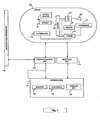
- Figure 1 schematically illustrates an in-vivo system in accordance with some embodiments of the present invention.
- One or more components of the system may be used in conjunction with, or may be operatively associated with, the devices and/or components described herein or other in-vivo devices in accordance with embodiments of the invention.
- the system may include a device 140 having a sensor, e.g., an imager 146, one or more illumination sources 142, an optical system 150, an internal magnet 151, a power source 145, and a transceiver 141.
- device 140 may be implemented using a swallowable capsule, but other sorts of devices or suitable implementations may be used. Outside a patient's body may be, for example, an external receiving unit 112, a magnetic field generator 125 and an external capsule position control unit 122.
- a storage unit 119 which may be or include for example one or more of a memory, a database, etc. or other storage systems, a processor 114, and a monitor 118. In some embodiments, for example, processor 114, storage unit 119 and/or monitor 118 may be implemented as a workstation 117, e.g., a computer or a computing platform.
- Transceiver 141 may operate using radio waves; but in some embodiments, such as those where device 140 is or is included within an endoscope, transceiver 141 may transmit/receive data via, for example, wire, optical fiber and/or other suitable methods. Other known wireless methods of transmission may be used. Transceiver 141 may include, for example, a transmitter module or sub-unit and a receiver module or sub-unit, or an integrated transceiver or transmitterreceiver. In one embodiment, transceiver 141 includes at least a modulator for receiving an image signal from the sensor 146, a radio frequency (RF) amplifier, an impedance matcher and an antenna 148.
- RF radio frequency
- the modulator converts the input image signal having a cutoff frequency f c of less than 5 MHz to an RF signal having a carrier frequency f r , typically in the range of 1 GHz. While in one embodiment, the signal is an analog signal, the modulating signal may be digital rather than analog.
- the carrier frequency may be in other bands, e . g . a 400MHz band.
- the modulated RF signal has a bandwidth of f t .
- the impedance matcher matches the impedance of the circuit to that of the antenna.
- Other transceivers or arrangements of transceiver components may be used. For example, alternate embodiments may not include a matched antenna or may include a transceiver without a matching circuit.
- the device 140 may have different configurations and include other sets of components. Other frequencies may be used.
- sensors other than image sensors may be used, such as pH meters, temperature sensors, pressure sensors, etc. and input RF signals other than image signals may be used.
- the transceiver 141 may send different types of signals, including for example telemetry signals, image signals and beacon signals. Other types of signals may be transmitted by transceiver 141.
- the signal types may vary in several parameters, such as the length of the signal burst, the transmission frequency of the signal, the rate of sending the signal, the power used to transmit the signal, the content of the sent signal, etc.
- Information sent from the device 140 may include information sensed by sensors in the device such as images, pH, temperature, location and pressure.
- Information sent from the device 140 may include telemetry information, regarding the capsule ID, time counter, image type data and the status of components in the device, such as current image capturing mode of the imager or estimated remaining power of the device power source.
- the signals may be sent separately or as part as a larger frame, for example a frame including both telemetry-type and image-type signals. Beacon signals may typically be transmitted separately, and not in a frame which may include image data or other types of signals.
- Device 140 typically may be or may include an autonomous swallowable capsule, but device 140 may have other shapes and need not be swallowable or autonomous. Embodiments of device 140 are typically autonomous, and are typically self-contained. For example, device 140 may be a capsule or other unit where all the components are substantially contained within a container or shell, and where device 140 does not require any wires or cables to, for example, receive power or transmit information. In some embodiments, device 140 may be autonomous and non-remote-controllable; in another embodiment, device 140 may be partially or entirely remote-controllable.
- device 140 may include an in-vivo video camera, for example, imager 146, which may capture and transmit images of, for example, the GI tract while device 140 passes through the GI lumen. Other lumens and/or body cavities may be imaged and/or sensed by device 140.
- imager 146 may include, for example, a Charge Coupled Device (CCD) camera or imager, a Complementary Metal Oxide Semiconductor (CMOS) camera or imager, a digital camera, a stills camera, a video camera, or other suitable imagers, cameras, or image acquisition components.
- CCD Charge Coupled Device
- CMOS Complementary Metal Oxide Semiconductor
- imager 146 in device 140 may be operationally connected to transceiver 141.
- Transceiver 141 may transmit images to, for example, external transceiver or receiver/recorder 112 (e.g., through one or more antennas), which may send the data to processor 114 and/or to storage unit 119.
- Transceiver 141 may also include control capability, although control capability may be included in a separate component, e.g., processor 147.
- Transceiver 141 may include any suitable transmitter able to transmit image data, other sensed data, and/or other data (e.g., control data, beacon signal, etc.) to a receiving device.
- Transceiver 141 may also be capable of receiving signals/commands, for example from an external transceiver.
- transceiver 141 may include an ultra low power Radio Frequency (RF) high bandwidth transmitter, possibly provided in Chip Scale Package (CSP).
- RF Radio Frequency
- CSP Chip Scale Package
- transceiver 141 may transmit/receive via antenna 148.
- Transceiver 141 and/or another unit in device 140 e.g., a controller or processor 147, may include control capability, for example, one or more control modules, processing module, circuitry and/or functionality for controlling device 140, for controlling the operational mode or settings of device 140, and/or for performing control operations or processing operations within device 140.
- transceiver 141 may include a receiver which may receive signals (e.g., from outside the patient's body), for example, through antenna 148 or through a different antenna or receiving element
- signals or data may be received by a separate receiving component in device 140.
- Power source 145 may include one or more batteries or power cells.
- power source 145 may include silver oxide batteries, lithium batteries, other suitable electrochemical cells having a high energy density, or the like. Other suitable power sources may be used.
- power source 145 may receive power or energy from an external power source (e.g., an electromagnetic field generator), which may be used to transmit power or energy to in-vivo device 140.
- an external power source e.g., an electromagnetic field generator
- transceiver 141 may include a processing unit, processor or controller for example, to process signals and/or data generated by imager 146.
- the processing unit may be implemented using a separate component within device 140, e.g., controller or processor 147, or may be implemented as an integral part of imager 146, transceiver 141, or another component, or may not be needed.
- the processing unit may include, for example, a Central Processing Unit (CPU), a Digital Signal Processor (DSP), a microprocessor, a controller, a chip, a microchip, a controller, circuitry, an Integrated Circuit (IC), an Application-Specific Integrated Circuit (ASIC), or any other suitable multi-purpose or specific processor, controller, circuitry or circuit.
- the processing unit or controller may be embedded in or integrated with transceiver 141, and may be implemented, for example, using an ASIC.
- imager 146 may acquire in-vivo images continuously, substantially continuously, or in a non-discrete manner, for example, not necessarily upon-demand, or not necessarily upon a triggering event or an external activation or external excitation, or in a periodic manner, an intermittent manner, or an otherwise non-continuous manner.
- device 140 may include one or more illumination sources 142, for example one or more Light Emitting Diodes (LEDs), "white LEDs", or other suitable light sources.
- Illumination sources 142 may, for example, illuminate a body lumen or cavity being imaged and/or sensed.
- An optical system 150 including, for example, one or more optical elements, such as one or more lenses or composite lens assemblies, one or more suitable optical filters, or any other suitable optical elements, may optionally be included in device 140 and may aid in focusing reflected light onto imager 146, focusing illuminating light, and/or performing other light processing operations.
- device 140 may include a magnetic element 151.
- the magnetic element may be cylindrically-shaped, oval, or spherical. Other shapes may be used, for example a cubic magnet.
- the magnetic element may be positioned inside the capsule's shell, adjacent to or near the capsule's inner wall or inner side of its shell. Such positioning may prevent injury of the tissue when the device is maneuvered by external forces, and may by advantageous for the maneuvering process itself since the control of the capsule may be more precise.
- Magnetic field generator 125 may produce a magnetic force, for example to exert a moment force on the magnet 151 located in the in vivo device, thereby causing the in vivo device to be maneuvered in the somersault manner described below.
- a position control unit 122 may be used to control the strength and direction of the magnetic field generator 125, according to the direction that the user may want to maneuver the device.
- the magnetic field generator 125 may be included in a mobile unit, for example a hand-held unit, that may be movable by a health care specialist adjacent a patient's body, in order to control the position of the in vivo device while it is in vivo.
- the position control unit 122 may operate by getting feedback from the device 140, for example, feedback based on image analysis or analysis of input from sensors other than an image sensor that may be included in device 140. Based on image analysis (or for example pressure data analysis or temperature data analysis) the position control unit 122 or any other suitable processor which may be in communication with position control unit 122, may cause changes in the external magnetic field that may stop or spin or otherwise automatically control movement of the device 140.
- the components of device 140 may be enclosed within a housing or shell, e.g., capsule-shaped, oval, or having other suitable shapes.
- the housing or shell may be substantially transparent, and/or may include one or more portions, windows or domes that may be substantially transparent
- one or more illumination source(s) 142 within device 140 may illuminate a body lumen through a transparent, window or dome; and light reflected from the body lumen may enter the device 140, for example, through the same transparent or portion, window or dome, or, optionally, through another transparent portion, window or dome, and may be received by optical system 150 and/or imager 146.
- optical system 150 and/or imager 146 may receive light, reflected from a body lumen, through the same window or dome through which illumination source(s) 142 illuminate the body lumen.
- the device 140 while device 140 traverses a patient's GI tract, the device 140 transmits image and possibly other data to components located outside the patient's body, which receive and process the data.
- receiving unit 112 is located outside the patient's body in one or more locations.
- the receiving unit 112 may typically include, or be operatively associated with, for example, one or more antennas, or an antenna array (not shown), for receiving and/or transmitting signals from/to device 140.
- Receiving unit 112 typically includes an image receiver storage unit.
- the image receiver 112 and image receiver storage unit are small and portable, and are typically worn on the patient's body (or located in close proximity to the patient's body) during recording of the images, at least until the image capturing procedure is determined to be terminated.
- device 140 may communicate with an external receiving and display system (e.g., workstation 117 or monitor 118) to provide display of data, control, or other functions.
- an external receiving and display system e.g., workstation 117 or monitor 118
- power may be provided to device 140 using an internal battery, an internal power source, or a wireless system able to receive power.
- Other embodiments may have other configurations and capabilities. For example, components may be distributed over multiple sites or units, and control information or other information may be received from an external source.
- Processor 114 may include a processing unit, processor or controller.
- the processing unit may include, for example, a CPU, a DSP, a microprocessor, a controller, a chip, a microchip, a controller, circuitry, an IC, an ASIC, or any other suitable multi-purpose or specific processor, controller, circuitry or circuit.
- Data processor 114 may analyze the data received via external receiver/recorder 112 from device 140, and may be in communication with storage unit 119, e.g., transferring frame data to and from storage unit 119. Data processor 114 may provide the analyzed data to monitor 118, where a user (e.g., a physician) may view or otherwise use the data. In some embodiments, data processor 114 may be configured for real time processing and/or for post processing to be performed and/or viewed at a later time.
- control capability e.g., delay, timing, etc
- a suitable external device such as, for example, data processor 114 or external receiver/recorder 112 having a transmitter or transceiver
- Monitor 118 may include, for example, one or more screens, monitors, or suitable display units. Monitor 118, for example, may display one or more images or a stream of images captured and/or transmitted by device 140, e.g., images of the GI tract or of other imaged body lumen or cavity. Additionally or alternatively, monitor 118 may display, for example, control data, location or position data (e.g., data describing or indicating the location or the relative location of device 140), orientation data, and various other suitable data. In some embodiments, for example, both an image and its position (e.g., relative to the body lumen being imaged) or location may be presented using monitor 118 and/or may be stored using storage unit 119. Other systems and methods of storing and/or displaying collected image data and/or other data may be used.
- device 140 may transmit image information in discrete portions. Each portion may typically correspond to an image or a frame; other suitable transmission methods may be used. For example, in some embodiments, device 140 may capture and/or acquire an image once every half second, and may transmit the image data to the external receiving unit 112. Other constant and/or variable capture rates and/or transmission rates may be used.
- the device may be moved along the body lumen, for example pulled in the direction of the gradient vector of the external magnetic force. Such type of movement may injure the delicate tissue wall.
- a permanent magnet or other suitable compomnent having a magnetic dipole When placed in a magnetic field, magnetic dipoles typically align their axes to be parallel with the field line.
- a permanent magnet or other suitable compomnent having a magnetic dipole which is placed within or on an in vivo device, when placed in a rotating magnetic field, will typically rotate so as to maintain alignment with the field.
- the rotating motion of the magnet will cause the device body to rotate with it, enbling the device to progress through a body lumen in a rotating, typically head to toe or sumersaulting motion.
- the rotating motion is caused by a N/S rotation of a magnet outside a patient's body.
- the rotating magnetic field may be produced by other means, such as a rotating magnetic field generator.
- control of the rotating field may be manual or without manual intervention.
- the device is preferably rolled around its center of mass, in a somersault manner, and the movement of the capsule is performed by head-to-tail rolling along the longitudinal axis of the device, instead of dragging or pulling it along the lumen without rotation.
- rolling or a somersaulting motion of the device is most effective in voluminous lumens, such as the stomach or colon.
- Such motion of a device may also be used in tube like lumens, such as the esophagus.
- the capsule may initially be positioned at P1 in a certain orientation, then may be rolled around its longitudinal axis to position and orientation P2, then P3.
- Such movement may reduce the risk of injured tissue, since the device does not graze the tissue of the walls or rub against it,.
- the position of the internal magnet or magnets within the device may preferably be away from the center of mass of the device.
- the center of mass is typically calculated without the magnets' addition, and the magnets are positioned on one side of the center of mass, in order to create an asymmetrical center of mass in the capsule.
- the magnet may be positioned on the side of the device which is near the imager.
- the device may have two imagers, for example one on each side of the longitudinal axis of the device.
- the two images may have different functional capabilities.
- One imager may be narrowly focused for viewing the near tissue, and the other may be configured for imaging a wider field of view.
- the magnet may be positioned on the side of the imager with the narrow field of view, focused on the near tissue, in order that the center of mass may be located closer to that side, and the device may rest on the tissue as a result
- the device may have one type of sensor, i.e. an imager, on one side, and another type of sensor on the other side, i.e. a pressure sensor, a pH sensor or an image sensor accompanied by an optical system to perform an optical biopsy.
- the magnet may typically be positioned near the side of the device which may functionally be required to be positioned closer to the GI tract wall tissue.
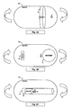
- Figs. 3A, 3B and 3C are schematic side view illustrations of an in vivo imaging device according to three different embodiments of the invention.
- the device changes position and/or orientation by applying an external moment force, which causes the somersault-type movement, rather than applying an external gradient force which creates the pulling movement and may injure the tissue.
- the moment force may be created around the center of gravity of the device.
- the magnetic force applied to create a moment force that may move the device may be weaker than the force required to move the capsule in a certain gradient. Therefore, embodiments of the invention may be advantageous in enery consumption.
- Fig. 3A shows the in vivo imaging device with the center of mass marked by point G.
- the position of the magnet affects the center of mass of the device, and is chosen to be on the side of the device which needs to be closer to the tissue.
- the imager needs to be close to the tissue in order to enable optical biopsy functionality.
- the location of the device's center of gravity (and the magnet) will be selected as the side with the optical biopsy imager.
- the device may be configured for performing a thorough scanning of the stomach, as will be described in Fig. 3 hereinbelow.
- Fig. 3B shows another embodiment of the magnetic elements within the capsule device.
- the in vivo device includes a tube element which may hold the magnet.
- the tube can be positioned along a longitudinal axis of the device, but can also be positioned diagonally or along latitudinal axis.
- the magnet element placed within the tube can move freely from one side of the tube to the other.
- the device's center of gravity, G may also change with the movement of the magnet element
- the center of gravity of the in vivo device may be controlled externally by changing the direction or the intensity of the external magnetic field.
- the field of view of the device may be controlled externally by the magnetic field.
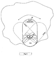
- Fig. 4 illustrates an exemplary movement of the in vivo imaging device in a relatively large organ such as the stomach.
- the center of gravity may be selected to be on the side of the device which is opposit the imaging side, and the device may be controlled to move the imaging head in a circular manner in order to cover the whole organ.
- the heavier side of the device which is the side of the center of gravity, may be the side of the magnet placement. In a preferred embodiment, this side of the device may be close to the tissue or may rest on it as shown in the embodiments of Figs. 3A-C , and may be positioned in a specific spot in the organ.
- the imaging head position may be controlled externally by the magnetic field generated by magnetic field generator 125 and controlled to a certain wanted position by position control unit 122.
- the device may be controlled to move in a circular manner, in order to cover 360° and obtain a complete view of the organ.
- Another embodiment which may use a similar configuration is a device which is configured to catch bio-markers. The wider span of motion performed by the lighter side of the device may be used to attract bio-markers, thereby increasing the chance of catching the biomarker during the procedure.
Landscapes
- Health & Medical Sciences (AREA)
- Life Sciences & Earth Sciences (AREA)
- Surgery (AREA)
- Engineering & Computer Science (AREA)
- General Health & Medical Sciences (AREA)
- Veterinary Medicine (AREA)
- Public Health (AREA)
- Animal Behavior & Ethology (AREA)
- Molecular Biology (AREA)
- Medical Informatics (AREA)
- Biomedical Technology (AREA)
- Heart & Thoracic Surgery (AREA)
- Physics & Mathematics (AREA)
- Biophysics (AREA)
- Nuclear Medicine, Radiotherapy & Molecular Imaging (AREA)
- Pathology (AREA)
- Optics & Photonics (AREA)
- Robotics (AREA)
- Radiology & Medical Imaging (AREA)
- Human Computer Interaction (AREA)
- Endoscopes (AREA)
- Measurement Of The Respiration, Hearing Ability, Form, And Blood Characteristics Of Living Organisms (AREA)
Description
- The present invention relates to an in-vivo device and method such as for imaging an in-vivo lumen. More specifically, the present invention relates to a method and apparatus in an in-vivo system for magnetically positioning and maneuvering an in-vivo imaging device.
- Known devices may be helpful in providing in-vivo sensing, such as imaging or pH sensing. Autonomous in-vivo sensing devices, such as swallowable or ingestible capsules or other devices, may move through a body lumen, sensing as they move along. The devices are typically autonomous in-vivo sensing device such as an imaging device and may include, for example, an imager for obtaining images from inside a body cavity or lumen, such as the gastrointestinal (GI) tract while the in-vivo imaging device passes through the GI lumen. The imager may, for example, be associated with an optical system, and optionally a transceiver and an antenna. Some of these devices use a wireless connection to transmit image data. Other devices, systems and methods for in-vivo sensing of passages or cavities within a body, and for sensing and gathering information (e.g., image information, pH information, temperature information, electrical impedance information, pressure information, etc.), are known in the art.
- Such devices may passively or actively progress through a body lumen, e.g., the gastrointestinal (GI) tract, for example, pushed along by natural peristalsis. However, in some cases it may be useful to control the position of the device, for example if a doctor wants to view a specific internal area, or in order to make sure that an internal organ was completely covered by the imaging device.
- Magnetically controlling movement of an in vivo device has been described, for example in
US Patent Number 4,278,077 in which there is described a current source that generats a magnetic field outside a patient's body. The magnetic field acts on a permanent magnets in a miniature camera device swallowed by the patient and thus moves the camera device in the stomach. -
US Patent Number 6,776,165 to Jin discloses a navigation system and navigatable capsules for remote-controlled imaging, biopsy and programmable drug release within the body of an animal. The components of the system comprise a capsule dimensioned and shaped to move within the body. An anisotropic magnetic component is mechanically coupled to the capsule to move or orient the body in relation to an applied magnetic field, and a magnetic field generating system external of the body generates a three dimensionally oriented magnetic field within the body to move or orient capsule.US Patent Number 7,182,089 to Ries discloses a magnetically navigable device with a magnet element that has a greater extent in one direction. The magnet element is arranged asymmetrically with respect to a central axis of the device, which points in the direction in which the magnet element extends. The magnetic element interacts with a gravitational force and a compensating magnetic force generated by external magnetic field gradients, which cause rotation of the magnetic element around the axis of the device to a to position counter to the gravitational force. - Prior art methods typically enable a specific but fixed point of view to an in vivo imaging, not easily enabling widening and/or changing the viewing angle during the device's progress in the lumen. Additionally, prior art methods of moving a device in vivo typically cause the device to be pulled or dragged in the lumen, possibly causing patient discomfort and abrasion of the tissue lining.
-
US 2003/0229268 (Uchiyama et al. ) discloses an encapsulated endoscope system that includes an encapsulated endoscope that rotates to develop a thrust, and an imaging unit and an image processing unit. The image processing unit produces an image that results from rotation of the image data, according to the rotational phase of the encapsulated endoscope. -
US 2006/0063974 (Uchiyama et al. ) discloses a guided capsule 3 that includes a magnet 16 to act on a rotating electromagnetic field, and that has a spiral projection portion 12 provided on the outer peripheral surface of the capsule in order to convert a rotational movement of the capsule, which is generated by the magnet 16 and a rotating electromagnetic field, into a thrust force. -
WO 2008/026549 (Uchiyama et al. ) discloses a capsule guiding system that includes an electrode pad (7), a head (3) for fixing/arranging the electrode pad (7), a magnetic field generation device (1) for moving an encapsulated endoscope (6), a position/direction calculation unit (12), and a control unit (13). An absolute position and/or absolute direction of the encapsulated endoscope (6) with respect to the magnetic field generation device (1) is obtained, and the control unit (13) controls the magnetic field generation device (1) according to the absolute position and/or the absolute direction of the encapsulated endoscope (6). - According to the present invention, there is provided a system as set forth in the appended claims.
- Embodiments of the invention provide a system for controlling movement of an imaging device in vivo which do not suffer from the shortcomings of the prior art.
- According to one embodiment, there is provided an in vivo imaging system comprising:
- an imaging device having a longitudinal axis, a centre of mass and a magnetic component, wherein the magnetic component is positioned within the imaging device so that it does not coincide with the centre of mass, said device to be inserted into a patient's body; and
- a magnetic field generator for generating a rotating magnetic field outside the patient's body;
- wherein the magnetic field generator is provided with control means to advance the rotating magnetic field along the patient's body in a desired direction.
- According to some embodiments parameters of the rotating magnetic field can be controlled either automatically or manually. According to some embodiments controlling parameters of the rotating magnetic field based on input from the imaging device (such as image data or other data that may be collected by the device).
- The imaging device may be caused to halt at a point in the patient's esophagus, said point enabling the device a view of the patient's z-line; and causing the device to rotate around its longitudinal axis.
- . The swallowable capsule may be produced by enclosing within a capsule shaped housing an imager and illumination elements, thereby producing an imaging capsule; calculating the center of mass of the imaging capsule; and positioning a magnetic component within or on the imaging capsule, such that the magnetic component position does not coincide with the center of mass.
- The swallowable capsule may alternatively be produced by enclosing within a device housing, said housing having at a viewing end a viewing window, a magnetic component, an imager and illumination elements, thereby producing an imaging device; and creating a center of mass of the device at an end of the device opposite the viewing end.
- The principles and operation of the system, apparatus, and method according to the present invention may be better understood with reference to the drawings, and the following description, it being understood that these drawings are given for illustrative purposes only and are not meant to be limiting, wherein:
-
Figure 1 is a schematic illustration of an in-vivo system according to an embodiment of the invention; -
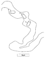
Figure 2 is a schematic illustration of an in-vivo device tumbling along a GI tract according to an embodiment of the present invention; -
Figures 3A, 3B and 3C , are schematic side view illustrations of an in vivo imaging device according to three different embodiments of the invention; and -
Figure 4 is a schematic illustration of an in-vivo imaging device according to one embodiment of the invention. - In the following detailed description, numerous specific details are set forth in order to provide a thorough understanding of the present invention. However, it will be understood by those skilled in the art that the present invention may be practiced without these specific details. In other instances, well-known methods, procedures, and components have not been described in detail so as not to obscure the present invention.
- Some embodiments of the present invention are directed to an in-vivo device that may be inserted into a body lumen, e.g., the gastro-intestinal (GI) tract, for example, from outside the body. Some embodiments are directed to a typically one time use or partially single use detection and/or analysis device. Some embodiments are directed to in-vivo sensing devices that may be passed through other body lumens, for example, through blood vessels, the reproductive tract, or the like. The in-vivo device may be, for example, a sensing device, an imaging device, a diagnostic device, a detection device, an analysis device, a therapeutic device, or a combination thereof. In some embodiments, the in-vivo device may include an image sensor or an imager and/or other suitable components. Some embodiments of the present invention may be directed to other imaging devices, not necessarily in-vivo imaging.
- Controlling and positioning an in vivo imaging device, for example a swallowable imaging capsule, may be useful in certain cases. For example, when the patient complains about pain in the throat, the health care professional may want to closely examine the patient's esophagus, and spend extra time around the the border between the squamous lined epithelium of the esophagus and the columnar epithelium of the stomach (the Z-line), in order to make sure it is fully viewed from several directions by the imaging device. In this case, it may be useful to stop the device at a certain point in the esophagus, for example just before the Z-line, and twist or rotate it around its longitudinal axis in a circular manner in order to capture a complete view of the in vivo area. In a preferred embodiment, the images of the Z-line are captured from different directions. The health care professional may wish to inspect the patient's stomach, an organ which is typically much larger than the imaging device. When a capsule is moving independently with no external control, it may tumble arbitrarily around the stomach. Preferably, the doctor would want to make sure that all of the stomach's tissue is examined, and that images covering the whole area of interest are captured by the device.
- Devices, systems and methods according to some embodiments of the present invention, including for example in-vivo sensing devices, receiving systems and/or display systems, may be similar to embodiments described in United States Patent Number
5,604,531 to Iddan et al. , entitled "In-vivo Video Camera System", and/or in United States Patent Number7,009,634 to Iddan et al. , entitled "Device for In-Vivo Imaging", all of which are hereby incorporated by reference in their entirety. Devices, systems and methods according to some embodiments of the present invention, may be similar to embodiments described in PCT Patent Application Publication NumberWO2006059331 , entitled "TWO-WAY COMMUNICATION IN AN AUTONOMOUS IN VIVO DEVICE", which discloses an autonomous in-vivo sensing device that includes an in-vivo transceiver to both transmit wireless signals to for example an external receiver, and to receive wireless signals from for example an external transmitter. The application further discloses that wireless signals received by the in-vivo transceiver may be or may include command or control signals that may activate, de-activate or alter an operational state of one or more functions of the in-vivo device. The wireless signals transmitted by the in-vivo transceiver may be or include sensory data such as for example image data that may be collected by the in-vivo sensing device. - Devices and systems as described herein may have other configurations and/or sets of components. For example, an external receiver/recorder unit, a processor and a monitor, e.g., in a workstation such as those described in the above publications, may be suitable for use with some embodiments of the present invention. The present invention may be practiced using an endoscope, needle, stent, catheter, etc. Some in-vivo devices may be capsule shaped, or may have other shapes, for example, a peanut shape or tubular, spherical, conical, or other suitable shapes.
- Some embodiments of the present invention may include, for example, a typically swallowable in-vivo device. The in-vivo device need not be swallowable, and may have other shapes or configurations. Some embodiments may be used in various body lumens, for example, the GI tract, blood vessels, the urinary tract, the reproductive tract, or the like.
- Embodiments of the in-vivo device of the present invention are typically controllable by an external magnetic force. The in-vivo device may be or may include a capsule or other unit where all the components are substantially contained within a container, housing or shell, and where the in-vivo device does not require any wires or cables to, for example, receive power/commands or transmit information. The in-vivo device may communicate with an external receiving and display system to provide display of data, control, or other functions. For example, power may be provided by an internal battery or an internal power source, or using a wired or wireless power-receiving system. Other embodiments may have other configurations and capabilities. For example, components may be distributed over multiple sites or units. Control information or other information may typically be received from an external source.
- Devices, systems and methods in accordance with some embodiments of the invention may be used, for example, in conjunction with a device which may be inserted into a human body or swallowed by a person. However, embodiments of the invention are not limited in this regard, and may be used, for example, in conjunction with a device which may be inserted into, or swallowed by, a non-human body or an animal body. Other embodiments of the invention need not be used with in vivo imaging devices, and may be used for enhancing images obtained by other types of imaging devices, such as digital cameras, or virtual imaging devices.
-
Figure 1 schematically illustrates an in-vivo system in accordance with some embodiments of the present invention. One or more components of the system may be used in conjunction with, or may be operatively associated with, the devices and/or components described herein or other in-vivo devices in accordance with embodiments of the invention. - In some embodiments, the system may include a
device 140 having a sensor, e.g., animager 146, one ormore illumination sources 142, anoptical system 150, aninternal magnet 151, apower source 145, and atransceiver 141. In some embodiments,device 140 may be implemented using a swallowable capsule, but other sorts of devices or suitable implementations may be used. Outside a patient's body may be, for example, anexternal receiving unit 112, amagnetic field generator 125 and an external capsuleposition control unit 122. Astorage unit 119 which may be or include for example one or more of a memory, a database, etc. or other storage systems, aprocessor 114, and amonitor 118. In some embodiments, for example,processor 114,storage unit 119 and/or monitor 118 may be implemented as aworkstation 117, e.g., a computer or a computing platform. -
Transceiver 141 may operate using radio waves; but in some embodiments, such as those wheredevice 140 is or is included within an endoscope,transceiver 141 may transmit/receive data via, for example, wire, optical fiber and/or other suitable methods. Other known wireless methods of transmission may be used.Transceiver 141 may include, for example, a transmitter module or sub-unit and a receiver module or sub-unit, or an integrated transceiver or transmitterreceiver. In one embodiment,transceiver 141 includes at least a modulator for receiving an image signal from thesensor 146, a radio frequency (RF) amplifier, an impedance matcher and anantenna 148. The modulator converts the input image signal having a cutoff frequency fc of less than 5 MHz to an RF signal having a carrier frequency fr, typically in the range of 1 GHz. While in one embodiment, the signal is an analog signal, the modulating signal may be digital rather than analog. The carrier frequency may be in other bands, e.g. a 400MHz band. The modulated RF signal has a bandwidth of ft. The impedance matcher matches the impedance of the circuit to that of the antenna. Other transceivers or arrangements of transceiver components may be used. For example, alternate embodiments may not include a matched antenna or may include a transceiver without a matching circuit. In alternate embodiments, thedevice 140 may have different configurations and include other sets of components. Other frequencies may be used. In yet further embodiments, sensors other than image sensors may be used, such as pH meters, temperature sensors, pressure sensors, etc. and input RF signals other than image signals may be used. - The
transceiver 141 may send different types of signals, including for example telemetry signals, image signals and beacon signals. Other types of signals may be transmitted bytransceiver 141. The signal types may vary in several parameters, such as the length of the signal burst, the transmission frequency of the signal, the rate of sending the signal, the power used to transmit the signal, the content of the sent signal, etc. Information sent from thedevice 140 may include information sensed by sensors in the device such as images, pH, temperature, location and pressure. Information sent from thedevice 140 may include telemetry information, regarding the capsule ID, time counter, image type data and the status of components in the device, such as current image capturing mode of the imager or estimated remaining power of the device power source. The signals may be sent separately or as part as a larger frame, for example a frame including both telemetry-type and image-type signals. Beacon signals may typically be transmitted separately, and not in a frame which may include image data or other types of signals. -
Device 140 typically may be or may include an autonomous swallowable capsule, butdevice 140 may have other shapes and need not be swallowable or autonomous. Embodiments ofdevice 140 are typically autonomous, and are typically self-contained. For example,device 140 may be a capsule or other unit where all the components are substantially contained within a container or shell, and wheredevice 140 does not require any wires or cables to, for example, receive power or transmit information. In some embodiments,device 140 may be autonomous and non-remote-controllable; in another embodiment,device 140 may be partially or entirely remote-controllable. - In some embodiments,
device 140 may include an in-vivo video camera, for example,imager 146, which may capture and transmit images of, for example, the GI tract whiledevice 140 passes through the GI lumen. Other lumens and/or body cavities may be imaged and/or sensed bydevice 140. In some embodiments,imager 146 may include, for example, a Charge Coupled Device (CCD) camera or imager, a Complementary Metal Oxide Semiconductor (CMOS) camera or imager, a digital camera, a stills camera, a video camera, or other suitable imagers, cameras, or image acquisition components. - In some embodiments,
imager 146 indevice 140 may be operationally connected totransceiver 141.Transceiver 141 may transmit images to, for example, external transceiver or receiver/recorder 112 (e.g., through one or more antennas), which may send the data toprocessor 114 and/or tostorage unit 119.Transceiver 141 may also include control capability, although control capability may be included in a separate component, e.g.,processor 147.Transceiver 141 may include any suitable transmitter able to transmit image data, other sensed data, and/or other data (e.g., control data, beacon signal, etc.) to a receiving device.Transceiver 141 may also be capable of receiving signals/commands, for example from an external transceiver. For example, in some embodiments,transceiver 141 may include an ultra low power Radio Frequency (RF) high bandwidth transmitter, possibly provided in Chip Scale Package (CSP). - In some embodiments,
transceiver 141 may transmit/receive viaantenna 148.Transceiver 141 and/or another unit indevice 140, e.g., a controller orprocessor 147, may include control capability, for example, one or more control modules, processing module, circuitry and/or functionality for controllingdevice 140, for controlling the operational mode or settings ofdevice 140, and/or for performing control operations or processing operations withindevice 140. According to some embodiments,transceiver 141 may include a receiver which may receive signals (e.g., from outside the patient's body), for example, throughantenna 148 or through a different antenna or receiving element According to some embodiments, signals or data may be received by a separate receiving component indevice 140. -
Power source 145 may include one or more batteries or power cells. For example,power source 145 may include silver oxide batteries, lithium batteries, other suitable electrochemical cells having a high energy density, or the like. Other suitable power sources may be used. For example,power source 145 may receive power or energy from an external power source (e.g., an electromagnetic field generator), which may be used to transmit power or energy to in-vivo device 140. - Optionally, in some embodiments,
transceiver 141 may include a processing unit, processor or controller for example, to process signals and/or data generated byimager 146. In another embodiment, the processing unit may be implemented using a separate component withindevice 140, e.g., controller orprocessor 147, or may be implemented as an integral part ofimager 146,transceiver 141, or another component, or may not be needed. The processing unit may include, for example, a Central Processing Unit (CPU), a Digital Signal Processor (DSP), a microprocessor, a controller, a chip, a microchip, a controller, circuitry, an Integrated Circuit (IC), an Application-Specific Integrated Circuit (ASIC), or any other suitable multi-purpose or specific processor, controller, circuitry or circuit. In some embodiments for example, the processing unit or controller may be embedded in or integrated withtransceiver 141, and may be implemented, for example, using an ASIC. - In some embodiments,
imager 146 may acquire in-vivo images continuously, substantially continuously, or in a non-discrete manner, for example, not necessarily upon-demand, or not necessarily upon a triggering event or an external activation or external excitation, or in a periodic manner, an intermittent manner, or an otherwise non-continuous manner. - In some embodiments,
device 140 may include one ormore illumination sources 142, for example one or more Light Emitting Diodes (LEDs), "white LEDs", or other suitable light sources.Illumination sources 142 may, for example, illuminate a body lumen or cavity being imaged and/or sensed. Anoptical system 150, including, for example, one or more optical elements, such as one or more lenses or composite lens assemblies, one or more suitable optical filters, or any other suitable optical elements, may optionally be included indevice 140 and may aid in focusing reflected light ontoimager 146, focusing illuminating light, and/or performing other light processing operations. - In a preferred embodiment,
device 140 may include amagnetic element 151. The magnetic element may be cylindrically-shaped, oval, or spherical. Other shapes may be used, for example a cubic magnet. Preferably, the magnetic element may be positioned inside the capsule's shell, adjacent to or near the capsule's inner wall or inner side of its shell. Such positioning may prevent injury of the tissue when the device is maneuvered by external forces, and may by advantageous for the maneuvering process itself since the control of the capsule may be more precise. -
Magnetic field generator 125 may produce a magnetic force, for example to exert a moment force on themagnet 151 located in the in vivo device, thereby causing the in vivo device to be maneuvered in the somersault manner described below. Aposition control unit 122 may be used to control the strength and direction of themagnetic field generator 125, according to the direction that the user may want to maneuver the device. Themagnetic field generator 125 may be included in a mobile unit, for example a hand-held unit, that may be movable by a health care specialist adjacent a patient's body, in order to control the position of the in vivo device while it is in vivo. - According to some embodiments the
position control unit 122 may operate by getting feedback from thedevice 140, for example, feedback based on image analysis or analysis of input from sensors other than an image sensor that may be included indevice 140. Based on image analysis (or for example pressure data analysis or temperature data analysis) theposition control unit 122 or any other suitable processor which may be in communication withposition control unit 122, may cause changes in the external magnetic field that may stop or spin or otherwise automatically control movement of thedevice 140. - In some embodiments, the components of
device 140 may be enclosed within a housing or shell, e.g., capsule-shaped, oval, or having other suitable shapes. The housing or shell may be substantially transparent, and/or may include one or more portions, windows or domes that may be substantially transparent For example, one or more illumination source(s) 142 withindevice 140 may illuminate a body lumen through a transparent, window or dome; and light reflected from the body lumen may enter thedevice 140, for example, through the same transparent or portion, window or dome, or, optionally, through another transparent portion, window or dome, and may be received byoptical system 150 and/orimager 146. In some embodiments, for example,optical system 150 and/orimager 146 may receive light, reflected from a body lumen, through the same window or dome through which illumination source(s) 142 illuminate the body lumen. - According to one embodiment, while
device 140 traverses a patient's GI tract, thedevice 140 transmits image and possibly other data to components located outside the patient's body, which receive and process the data. Typically, receivingunit 112 is located outside the patient's body in one or more locations. The receivingunit 112 may typically include, or be operatively associated with, for example, one or more antennas, or an antenna array (not shown), for receiving and/or transmitting signals from/todevice 140. Receivingunit 112 typically includes an image receiver storage unit. According to one embodiment, theimage receiver 112 and image receiver storage unit are small and portable, and are typically worn on the patient's body (or located in close proximity to the patient's body) during recording of the images, at least until the image capturing procedure is determined to be terminated. - In some embodiments,
device 140 may communicate with an external receiving and display system (e.g.,workstation 117 or monitor 118) to provide display of data, control, or other functions. For example, power may be provided todevice 140 using an internal battery, an internal power source, or a wireless system able to receive power. Other embodiments may have other configurations and capabilities. For example, components may be distributed over multiple sites or units, and control information or other information may be received from an external source. -
Processor 114 may include a processing unit, processor or controller. The processing unit may include, for example, a CPU, a DSP, a microprocessor, a controller, a chip, a microchip, a controller, circuitry, an IC, an ASIC, or any other suitable multi-purpose or specific processor, controller, circuitry or circuit. -
Data processor 114 may analyze the data received via external receiver/recorder 112 fromdevice 140, and may be in communication withstorage unit 119, e.g., transferring frame data to and fromstorage unit 119.Data processor 114 may provide the analyzed data to monitor 118, where a user (e.g., a physician) may view or otherwise use the data. In some embodiments,data processor 114 may be configured for real time processing and/or for post processing to be performed and/or viewed at a later time. In the case that control capability (e.g., delay, timing, etc) is external todevice 140, a suitable external device (such as, for example,data processor 114 or external receiver/recorder 112 having a transmitter or transceiver) may transmit one or more control signals todevice 140. -
Monitor 118 may include, for example, one or more screens, monitors, or suitable display units.Monitor 118, for example, may display one or more images or a stream of images captured and/or transmitted bydevice 140, e.g., images of the GI tract or of other imaged body lumen or cavity. Additionally or alternatively, monitor 118 may display, for example, control data, location or position data (e.g., data describing or indicating the location or the relative location of device 140), orientation data, and various other suitable data. In some embodiments, for example, both an image and its position (e.g., relative to the body lumen being imaged) or location may be presented usingmonitor 118 and/or may be stored usingstorage unit 119. Other systems and methods of storing and/or displaying collected image data and/or other data may be used. - Typically,
device 140 may transmit image information in discrete portions. Each portion may typically correspond to an image or a frame; other suitable transmission methods may be used. For example, in some embodiments,device 140 may capture and/or acquire an image once every half second, and may transmit the image data to theexternal receiving unit 112. Other constant and/or variable capture rates and/or transmission rates may be used. - In prior solutions, the device may be moved along the body lumen, for example pulled in the direction of the gradient vector of the external magnetic force. Such type of movement may injure the delicate tissue wall.
- When placed in a magnetic field, magnetic dipoles typically align their axes to be parallel with the field line. In a method according to an embodiment of the inevntion a permanent magnet or other suitable compomnent having a magnetic dipole, which is placed within or on an in vivo device, when placed in a rotating magnetic field, will typically rotate so as to maintain alignment with the field. The rotating motion of the magnet will cause the device body to rotate with it, enbling the device to progress through a body lumen in a rotating, typically head to toe or sumersaulting motion.
- According to one embodiment the rotating motion is caused by a N/S rotation of a magnet outside a patient's body. Accroding to other embodiments the rotating magnetic field may be produced by other means, such as a rotating magnetic field generator. Thus control of the rotating field may be manual or without manual intervention.
- Referring to
Fig. 2 , according to an embodiment of the present invention, the device is preferably rolled around its center of mass, in a somersault manner, and the movement of the capsule is performed by head-to-tail rolling along the longitudinal axis of the device, instead of dragging or pulling it along the lumen without rotation. - According to some embodiments rolling or a somersaulting motion of the device is most effective in voluminous lumens, such as the stomach or colon. Such motion of a device may also be used in tube like lumens, such as the esophagus.
- For example, as shown in
Fig. 2 , the capsule may initially be positioned at P1 in a certain orientation, then may be rolled around its longitudinal axis to position and orientation P2, then P3. Such movement may reduce the risk of injured tissue, since the device does not graze the tissue of the walls or rub against it,. To achieve such manner of movement, the position of the internal magnet or magnets within the device may preferably be away from the center of mass of the device. The center of mass is typically calculated without the magnets' addition, and the magnets are positioned on one side of the center of mass, in order to create an asymmetrical center of mass in the capsule. For example, in a device with a single imaging head, the magnet may be positioned on the side of the device which is near the imager. In another embodiment, the device may have two imagers, for example one on each side of the longitudinal axis of the device. The two images may have different functional capabilities. One imager may be narrowly focused for viewing the near tissue, and the other may be configured for imaging a wider field of view. In such embodiments, the magnet may be positioned on the side of the imager with the narrow field of view, focused on the near tissue, in order that the center of mass may be located closer to that side, and the device may rest on the tissue as a result In another embodiment, the device may have one type of sensor, i.e. an imager, on one side, and another type of sensor on the other side, i.e. a pressure sensor, a pH sensor or an image sensor accompanied by an optical system to perform an optical biopsy. The magnet may typically be positioned near the side of the device which may functionally be required to be positioned closer to the GI tract wall tissue. - Reference is now made to
Figs. 3A, 3B and 3C , which are schematic side view illustrations of an in vivo imaging device according to three different embodiments of the invention. In all these embodiments, the device changes position and/or orientation by applying an external moment force, which causes the somersault-type movement, rather than applying an external gradient force which creates the pulling movement and may injure the tissue. The moment force may be created around the center of gravity of the device. According to an embodiment of the invention, the magnetic force applied to create a moment force that may move the device may be weaker than the force required to move the capsule in a certain gradient. Therefore, embodiments of the invention may be advantageous in enery consumption. - In the first embodiment.
Fig. 3A shows the in vivo imaging device with the center of mass marked by point G. Typically, the position of the magnet affects the center of mass of the device, and is chosen to be on the side of the device which needs to be closer to the tissue. For example, in one embodiment, the imager needs to be close to the tissue in order to enable optical biopsy functionality. The location of the device's center of gravity (and the magnet) will be selected as the side with the optical biopsy imager. In another embodiment, the device may be configured for performing a thorough scanning of the stomach, as will be described inFig. 3 hereinbelow. -
Fig. 3B shows another embodiment of the magnetic elements within the capsule device. -
Fig. 3C illustrates a third embodiment according to the invention. In this embodiment, the in vivo device includes a tube element which may hold the magnet. The tube can be positioned along a longitudinal axis of the device, but can also be positioned diagonally or along latitudinal axis. The magnet element placed within the tube can move freely from one side of the tube to the other. The device's center of gravity, G, may also change with the movement of the magnet element In this embodiment, the center of gravity of the in vivo device may be controlled externally by changing the direction or the intensity of the external magnetic field. The field of view of the device may be controlled externally by the magnetic field. - Reference is now made to
Fig. 4 , which illustrates an exemplary movement of the in vivo imaging device in a relatively large organ such as the stomach. The center of gravity may be selected to be on the side of the device which is opposit the imaging side, and the device may be controlled to move the imaging head in a circular manner in order to cover the whole organ. The heavier side of the device, which is the side of the center of gravity, may be the side of the magnet placement. In a preferred embodiment, this side of the device may be close to the tissue or may rest on it as shown in the embodiments ofFigs. 3A-C , and may be positioned in a specific spot in the organ. The imaging head position may be controlled externally by the magnetic field generated bymagnetic field generator 125 and controlled to a certain wanted position byposition control unit 122. For example, the device may be controlled to move in a circular manner, in order to cover 360° and obtain a complete view of the organ. Another embodiment which may use a similar configuration is a device which is configured to catch bio-markers. The wider span of motion performed by the lighter side of the device may be used to attract bio-markers, thereby increasing the chance of catching the biomarker during the procedure.
Throughout the description and claims of this specification, the words "comprise" and "contain" and variations of them mean "including but not limited to", and they are not intended to (and do not) exclude other moieties, additives, components, integers or steps. Throughout the description and claims of this specification, the singular encompasses the plural unless the context otherwise requires. In particular, where the indefinite article is used, the specification is to be understood as contemplating plurality as well as singularity, unless the context requires otherwise.
Features, integers, characteristics, compounds, chemical moieties or groups described in conjunction with a particular aspect, embodiment or example of the invention are to be understood to be applicable to any other aspect, embodiment or example described herein unless incompatible therewith. All of the features disclosed in this specification (including any accompanying claims, abstract and drawings), and/or all of the steps of any method or process so disclosed, may be combined in any combination, except combinations where at least some of such features and/or steps are mutually exclusive. The invention is not restricted to the details of any foregoing embodiments.
The reader's attention is directed to all papers and documents which are filed concurrently with or previous to this specification in connection with this application and which are open to public inspection with this specification.
Claims (4)
- An in vivo imaging system comprising:an imaging device (140, 240) having a longitudinal axis, a centre of mass (G) and a magnetic component (20, 21, 23, 151), wherein the magnetic component (20, 21, 23, 151) is positioned within the imaging device (140, 240) so that it does not coincide with the centre of mass (G), said device (140, 240) to be inserted into a patient's body; anda magnetic field generator (125) for generating a rotating magnetic field outside the patient's body;wherein the magnetic field generator (125) is provided with control means to advance the rotating magnetic field along the patient's body in a desired direction (P1, P2, P3).
- The system as claimed in claim 1, wherein the control means comprises a position control unit (122) linked to a computer (117).
- The system as claimed in claim 2, wherein the position control unit (122) is operable to control parameters of the rotating magnetic field.
- The system as claimed in claim 3, wherein the computer (117) is configured to receive input signals from the imaging device (140, 240), and wherein the position control unit (122) is operable to control parameters of the rotating magnetic field based on the input signals from the imaging device (140, 240).
Applications Claiming Priority (1)
| Application Number | Priority Date | Filing Date | Title |
|---|---|---|---|
| US12/121,432 US8428685B2 (en) | 2001-09-05 | 2008-05-15 | System and method for magnetically maneuvering an in vivo device |
Publications (3)
| Publication Number | Publication Date |
|---|---|
| EP2119392A2 EP2119392A2 (en) | 2009-11-18 |
| EP2119392A3 EP2119392A3 (en) | 2009-12-30 |
| EP2119392B1 true EP2119392B1 (en) | 2014-04-16 |
Family
ID=40957572
Family Applications (1)
| Application Number | Title | Priority Date | Filing Date |
|---|---|---|---|
| EP09160289.6A Active EP2119392B1 (en) | 2008-05-15 | 2009-05-14 | Device, system and method for magnetically maneuvering an in vivo device |
Country Status (3)
| Country | Link |
|---|---|
| US (1) | US8428685B2 (en) |
| EP (1) | EP2119392B1 (en) |
| JP (1) | JP5873230B2 (en) |
Families Citing this family (20)
| Publication number | Priority date | Publication date | Assignee | Title |
|---|---|---|---|---|
| DE102006019987A1 (en) * | 2006-04-26 | 2007-10-31 | Siemens Ag | Endoscopic capsule for investigation of body openings, has induction coil with elongation along one axis, and magnetic element having magnetic dipole moment aligned perpendicular to longitudinal axis of induction coil |
| US8241206B2 (en) * | 2008-07-08 | 2012-08-14 | Olympus Medical Systems Corp. | System for guiding capsule medical device |
| US8235888B2 (en) * | 2008-07-08 | 2012-08-07 | Olympus Medical Systems Corp. | System for guiding capsule medical device |
| US20100010306A1 (en) * | 2008-07-08 | 2010-01-14 | Olympus Medical Systems Corp. | System for guiding capsule medical device |
| US20100130837A1 (en) * | 2008-11-25 | 2010-05-27 | The Smart Pill Corporation | Modular ingestible capsule |
| WO2011078028A1 (en) * | 2009-12-25 | 2011-06-30 | 株式会社堀場製作所 | Liquid characteristic analyzing apparatus |
| EP2347699B1 (en) * | 2010-01-22 | 2018-11-07 | Novineon Healthcare Technology Partners Gmbh | Capsule type endoscope including magnetic drive |
| CN103370001B (en) | 2010-12-30 | 2016-12-21 | 基文影像公司 | The system and method for image stream self-navigation capsule based on internal seizure |
| DE102011004825B4 (en) * | 2011-02-28 | 2019-05-02 | Siemens Healthcare Gmbh | A method of controlling the transport of a magnetic moment endoscope capsule |
| US9743942B2 (en) * | 2013-03-15 | 2017-08-29 | Christopher V. Beckman | Nanotechnology and other small scale injectable machines with multistage external magnetic and electrostatic actuation |
| US20130267788A1 (en) * | 2012-04-04 | 2013-10-10 | Ankon Technologies Co. Ltd. | System and Method for Orientation and Movement of Remote Objects |
| WO2013164826A1 (en) | 2012-05-04 | 2013-11-07 | Given Imaging Ltd. | System and method for automatic navigation of a capsule based on image stream captured in-vivo |
| EP2849627B1 (en) * | 2012-05-19 | 2020-07-08 | Capso Vision, Inc. | Optical wireless docking system for capsule camera |
| DE102012216797A1 (en) * | 2012-09-19 | 2014-03-20 | Siemens Aktiengesellschaft | Complete medical system for magnetic navigation |
| WO2015029033A1 (en) * | 2013-08-29 | 2015-03-05 | Given Imaging Ltd. | System and method for maneuvering coils power optimization |
| TWI520708B (en) * | 2013-09-26 | 2016-02-11 | 連吉時 | Magnetic control system for capsule endoscope |
| CN106659425B (en) | 2014-07-10 | 2020-09-18 | 基文影像公司 | Sensor strip configured to position an in vivo device and method of positioning |
| CN111543924A (en) * | 2020-05-28 | 2020-08-18 | 江苏数字鹰科技股份有限公司 | Ultra-miniature peep-in robot |
| CN111772558B (en) * | 2020-06-23 | 2023-03-17 | 李大欢 | Positioning device for digestive tract pathologic change endoscope |
| RU2771414C1 (en) * | 2021-01-28 | 2022-05-04 | Владимир Станиславович Крушельницкий | Apparatus for correcting the location of a video capsule in the small intestine |
Family Cites Families (85)
| Publication number | Priority date | Publication date | Assignee | Title |
|---|---|---|---|---|
| US3322374A (en) * | 1964-09-30 | 1967-05-30 | Jr James F King | Magnetohydrodynamic propulsion apparatus |
| US3683389A (en) * | 1971-01-20 | 1972-08-08 | Corning Glass Works | Omnidirectional loop antenna array |
| US3971362A (en) * | 1972-10-27 | 1976-07-27 | The United States Of America As Represented By The Administrator Of The National Aeronautics And Space Administration | Miniature ingestible telemeter devices to measure deep-body temperature |
| JPS5519124A (en) * | 1978-07-27 | 1980-02-09 | Olympus Optical Co | Camera system for medical treatment |
| US4431005A (en) * | 1981-05-07 | 1984-02-14 | Mccormick Laboratories, Inc. | Method of and apparatus for determining very accurately the position of a device inside biological tissue |
| US4429328A (en) * | 1981-07-16 | 1984-01-31 | Cjm Associates | Three-dimensional display methods using vertically aligned points of origin |
| US4651201A (en) * | 1984-06-01 | 1987-03-17 | Arnold Schoolman | Stereoscopic endoscope arrangement |
| JPH0820230B2 (en) | 1984-06-08 | 1996-03-04 | オリンパス光学工業株式会社 | Measuring endoscope |
| DE3440177A1 (en) | 1984-11-02 | 1986-05-15 | Friedrich Dipl.-Ing. 8031 Eichenau Hilliges | Television recording and replay device for endoscopy on human and animal bodies |
| US4689621A (en) * | 1986-03-31 | 1987-08-25 | The United States Of America As Represented By The Administrator Of The National Aeronautics And Space Administration | Temperature responsive transmitter |
| JPH0664243B2 (en) * | 1986-04-30 | 1994-08-22 | オリンパス光学工業株式会社 | Endoscope |
| US4844076A (en) * | 1988-08-26 | 1989-07-04 | The Johns Hopkins University | Ingestible size continuously transmitting temperature monitoring pill |
| JP2579372B2 (en) | 1989-12-04 | 1997-02-05 | 日本テキサス・インスツルメンツ株式会社 | Low power imaging device |
| JPH045833A (en) | 1990-04-23 | 1992-01-09 | Nec Corp | Junction-gate field-effect transistor |
| JPH04109927A (en) | 1990-08-31 | 1992-04-10 | Toshiba Corp | Electronic endoscope apparatus |
| JP2948900B2 (en) | 1990-11-16 | 1999-09-13 | オリンパス光学工業株式会社 | Medical capsule |
| JP2768029B2 (en) | 1991-02-19 | 1998-06-25 | 日新電機株式会社 | Digestive system diagnostic device |
| JP3078085B2 (en) * | 1991-03-26 | 2000-08-21 | オリンパス光学工業株式会社 | Image processing apparatus and image processing method |
| US5279607A (en) * | 1991-05-30 | 1994-01-18 | The State University Of New York | Telemetry capsule and process |
| JP3347385B2 (en) * | 1992-03-27 | 2002-11-20 | オリンパス光学工業株式会社 | Endoscope image processing device |
| JP3150448B2 (en) | 1992-10-05 | 2001-03-26 | オリンパス光学工業株式会社 | Medical capsule device |
| US5459605A (en) * | 1992-12-17 | 1995-10-17 | Paul S. Kempf | 3-D endoscope apparatus |
| JP3321235B2 (en) | 1993-04-07 | 2002-09-03 | オリンパス光学工業株式会社 | Medical capsule and medical capsule detection device |
| WO1996005768A1 (en) | 1994-08-19 | 1996-02-29 | Biosense, Inc. | Medical diagnosis, treatment and imaging systems |
| IL108352A (en) * | 1994-01-17 | 2000-02-29 | Given Imaging Ltd | In vivo video camera system |
| CA2145232A1 (en) * | 1994-03-24 | 1995-09-25 | Arie Avny | Viewing method and apparatus particularly useful for viewing the interior of the large intestine |
| JP3631265B2 (en) | 1994-04-27 | 2005-03-23 | オリンパス株式会社 | In-vivo observation device |
| US5515853A (en) * | 1995-03-28 | 1996-05-14 | Sonometrics Corporation | Three-dimensional digital ultrasound tracking system |
| US5924989A (en) * | 1995-04-03 | 1999-07-20 | Polz; Hans | Method and device for capturing diagnostically acceptable three-dimensional ultrasound image data records |
| US5697377A (en) * | 1995-11-22 | 1997-12-16 | Medtronic, Inc. | Catheter mapping system and method |
| GB9619470D0 (en) | 1996-09-18 | 1996-10-30 | Univ London | Imaging apparatus |
| US6248074B1 (en) * | 1997-09-30 | 2001-06-19 | Olympus Optical Co., Ltd. | Ultrasonic diagnosis system in which periphery of magnetic sensor included in distal part of ultrasonic endoscope is made of non-conductive material |
| US6240312B1 (en) * | 1997-10-23 | 2001-05-29 | Robert R. Alfano | Remote-controllable, micro-scale device for use in in vivo medical diagnosis and/or treatment |
| US6120453A (en) * | 1997-11-17 | 2000-09-19 | Sharp; William A. | Three-dimensional ultrasound system based on the coordination of multiple ultrasonic transducers |
| IL122578A (en) * | 1997-12-12 | 2000-08-13 | Super Dimension Ltd | Wireless six-degree-of-freedom locator |
| JP2000023980A (en) | 1998-07-08 | 2000-01-25 | Olympus Optical Co Ltd | Ultrasonograph |
| AU4644799A (en) | 1998-08-02 | 2000-03-14 | Super Dimension Ltd. | Intrabody navigation system for medical applications |
| WO2000047621A1 (en) * | 1999-02-12 | 2000-08-17 | Baxter Aktiengesellschaft | A method for producing a preparation based on fibrinogen and fibronectin as well as protein compositions obtainable according to this method |
| US7116352B2 (en) * | 1999-02-25 | 2006-10-03 | Visionsense Ltd. | Capsule |
| US8636648B2 (en) * | 1999-03-01 | 2014-01-28 | West View Research, Llc | Endoscopic smart probe |
| US6233476B1 (en) * | 1999-05-18 | 2001-05-15 | Mediguide Ltd. | Medical positioning system |
| WO2001006917A1 (en) | 1999-07-26 | 2001-02-01 | Super Dimension Ltd. | Linking of an intra-body tracking system to external reference coordinates |
| GB2352636B (en) | 1999-08-03 | 2003-05-14 | Univ College London Hospitals | Improved passage-travelling device |
| JP4295865B2 (en) | 1999-08-06 | 2009-07-15 | Hoya株式会社 | Radio capsule receiving system |
| JP4472069B2 (en) | 1999-11-10 | 2010-06-02 | オリンパス株式会社 | Medical capsule endoscope |
| IL134017A (en) | 2000-01-13 | 2008-04-13 | Capsule View Inc | Camera for viewing inside intestines |
| JP4338280B2 (en) | 2000-02-15 | 2009-10-07 | Hoya株式会社 | Capsule endoscope |
| JP2001224553A (en) | 2000-02-17 | 2001-08-21 | Asahi Optical Co Ltd | Imaging instrument for capusle endoscope |
| DE20122488U1 (en) | 2000-03-08 | 2005-12-15 | Given Imaging Ltd. | In vivo imaging system for use in applications such as imaging digestive tract, uses camera, illumination source and transmitter enclosed in capsule suitable for insertion into and passing through body lumens or cavities |
| US6632175B1 (en) * | 2000-11-08 | 2003-10-14 | Hewlett-Packard Development Company, L.P. | Swallowable data recorder capsule medical device |
| US20020177779A1 (en) * | 2001-03-14 | 2002-11-28 | Doron Adler | Method and system for detecting colorimetric abnormalities in vivo |
| EP1418845A4 (en) * | 2001-04-04 | 2006-06-07 | Given Imaging Ltd | Induction powered in vivo imaging device |
| IL143260A (en) | 2001-05-20 | 2006-09-05 | Given Imaging Ltd | Array system and method for locating an in vivo signal source |
| IL143259A (en) | 2001-05-20 | 2006-08-01 | Given Imaging Ltd | Method for moving an object through the colon |
| AU2002304266A1 (en) * | 2001-06-20 | 2003-01-02 | Given Imaging Ltd. | Motility analysis within a gastrointestinal tract |
| US6939292B2 (en) * | 2001-06-20 | 2005-09-06 | Olympus Corporation | Capsule type endoscope |
| US20030043263A1 (en) * | 2001-07-26 | 2003-03-06 | Arkady Glukhovsky | Diagnostic device using data compression |
| US20030117491A1 (en) * | 2001-07-26 | 2003-06-26 | Dov Avni | Apparatus and method for controlling illumination in an in-vivo imaging device |
| IL151049A0 (en) * | 2001-08-02 | 2003-04-10 | Given Imaging Ltd | In vivo imaging methods and devices |
| EP1432345B1 (en) * | 2001-09-24 | 2011-11-09 | Given Imaging Ltd. | System for controlling a device in vivo |
| JP4106895B2 (en) | 2001-10-31 | 2008-06-25 | Dic株式会社 | Molded laminated sheet |
| IL153510A0 (en) * | 2001-12-18 | 2003-07-06 | Given Imaging Ltd | Device, system and method for capturing in-vivo images with three-dimensional aspects |
| US7474327B2 (en) * | 2002-02-12 | 2009-01-06 | Given Imaging Ltd. | System and method for displaying an image stream |
| JP4234605B2 (en) * | 2002-02-12 | 2009-03-04 | ギブン イメージング リミテッド | System and method for displaying an image stream |
| US20030195415A1 (en) * | 2002-02-14 | 2003-10-16 | Iddan Gavriel J. | Device, system and method for accoustic in-vivo measuring |
| JP4009473B2 (en) * | 2002-03-08 | 2007-11-14 | オリンパス株式会社 | Capsule endoscope |
| JP3895618B2 (en) * | 2002-03-08 | 2007-03-22 | オリンパス株式会社 | Capsule endoscope |
| JP4363843B2 (en) * | 2002-03-08 | 2009-11-11 | オリンパス株式会社 | Capsule endoscope |
| JP3917885B2 (en) * | 2002-04-08 | 2007-05-23 | オリンパス株式会社 | Capsule endoscope system |
| US20030216622A1 (en) * | 2002-04-25 | 2003-11-20 | Gavriel Meron | Device and method for orienting a device in vivo |
| JP2004008341A (en) | 2002-06-04 | 2004-01-15 | Olympus Corp | Label for medical instrument and medical instrument |
| US7473218B2 (en) * | 2002-08-06 | 2009-01-06 | Olympus Corporation | Assembling method of capsule medical apparatus |
| JP4109927B2 (en) | 2002-08-20 | 2008-07-02 | セイコークロック株式会社 | Radio correction watch and method |
| US6776165B2 (en) | 2002-09-12 | 2004-08-17 | The Regents Of The University Of California | Magnetic navigation system for diagnosis, biopsy and drug delivery vehicles |
| WO2004028336A2 (en) | 2002-09-30 | 2004-04-08 | Given Imaging Ltd. | Reduced size imaging device |
| US7866322B2 (en) | 2002-10-15 | 2011-01-11 | Given Imaging Ltd. | Device, system and method for transfer of signals to a moving device |
| IL155175A (en) | 2003-03-31 | 2012-01-31 | Given Imaging Ltd | Diagnostic device using data compression |
| JP4153845B2 (en) * | 2003-08-11 | 2008-09-24 | オリンパス株式会社 | Medical device guidance system |
| DE10343494B4 (en) * | 2003-09-19 | 2006-06-14 | Siemens Ag | Magnetically navigable device for use in the field of medical endoscopy |
| JP4891535B2 (en) * | 2004-09-21 | 2012-03-07 | オリンパス株式会社 | Medical device guidance system |
| DE112005003031T5 (en) | 2004-12-01 | 2007-11-08 | Given Imaging Ltd. | Two-way communication in an autonomous device in the living organism |
| JP5064018B2 (en) * | 2005-12-28 | 2012-10-31 | オリンパスメディカルシステムズ株式会社 | Intra-subject introduction system |
| JP5015515B2 (en) | 2006-08-02 | 2012-08-29 | 伊藤超短波株式会社 | Muscle training equipment |
| US20090318761A1 (en) * | 2006-08-10 | 2009-12-24 | Elisha Rabinovitz | System and method for in vivo imaging |
| JP5084200B2 (en) | 2006-08-29 | 2012-11-28 | オリンパスメディカルシステムズ株式会社 | Capsule guidance system |
-
2008
- 2008-05-15 US US12/121,432 patent/US8428685B2/en active Active
-
2009
- 2009-05-14 EP EP09160289.6A patent/EP2119392B1/en active Active
- 2009-05-15 JP JP2009119052A patent/JP5873230B2/en active Active
Also Published As
| Publication number | Publication date |
|---|---|
| EP2119392A3 (en) | 2009-12-30 |
| US8428685B2 (en) | 2013-04-23 |
| JP2009273893A (en) | 2009-11-26 |
| JP5873230B2 (en) | 2016-03-01 |
| EP2119392A2 (en) | 2009-11-18 |
| US20090048484A1 (en) | 2009-02-19 |
Similar Documents
| Publication | Publication Date | Title |
|---|---|---|
| EP2119392B1 (en) | Device, system and method for magnetically maneuvering an in vivo device | |
| EP2113188B1 (en) | System and methods for determination of procedure termination | |
| EP1965698B1 (en) | System and method of in-vivo magnetic position determination | |
| Basar et al. | Ingestible wireless capsule technology: A review of development and future indication | |
| KR101111672B1 (en) | Medical wireless capsule-type endoscope system | |
| US8449452B2 (en) | In-vivo sensing system | |
| US7704205B2 (en) | System and method of obtaining images of a subject using a capsule type medical device | |
| JP3974769B2 (en) | Capsule medical device | |
| JP4166509B2 (en) | Capsule endoscope | |
| US20090318761A1 (en) | System and method for in vivo imaging | |
| JP2007167214A (en) | Apparatus and system for photographing in vivo image | |
| WO2006059338A2 (en) | Device, system and method of in-vivo electro-stimulation | |
| US8540623B2 (en) | Apparatus, system and method to indicate in-vivo device location | |
| JP2013511320A (en) | System and method for controlling power consumption of in-vivo devices | |
| US8206285B2 (en) | Apparatus, system and method to indicate in-vivo device location | |
| Uehara et al. | Capsule endoscope NORIKA system | |
| US8734329B2 (en) | Capsule medical device guiding system and magnetic field generating device | |
| JP5248911B2 (en) | Capsule medical device | |
| CN110269580A (en) | Robot system is peeped in a kind of micro radio | |
| JP5419333B2 (en) | In-vivo imaging device for observing the lumen of a human body | |
| JP2009125100A (en) | Radio feed system | |
| JP2005278817A (en) | Position detecting system for inside of examinee's body | |
| Sharma et al. | Finding the Possibility of a Wireless-Based e-Pill for Biomedical Applications | |
| EP1949847A1 (en) | Memory-type two-section endoscopic system |
Legal Events
| Date | Code | Title | Description |
|---|---|---|---|
| PUAI | Public reference made under article 153(3) epc to a published international application that has entered the european phase |
Free format text: ORIGINAL CODE: 0009012 |
|
| 17P | Request for examination filed |
Effective date: 20090514 |
|
| AK | Designated contracting states |
Kind code of ref document: A2 Designated state(s): AT BE BG CH CY CZ DE DK EE ES FI FR GB GR HR HU IE IS IT LI LT LU LV MC MK MT NL NO PL PT RO SE SI SK TR |
|
| PUAL | Search report despatched |
Free format text: ORIGINAL CODE: 0009013 |
|
| AK | Designated contracting states |
Kind code of ref document: A3 Designated state(s): AT BE BG CH CY CZ DE DK EE ES FI FR GB GR HR HU IE IS IT LI LT LU LV MC MK MT NL NO PL PT RO SE SI SK TR |
|
| 17Q | First examination report despatched |
Effective date: 20120320 |
|
| GRAP | Despatch of communication of intention to grant a patent |
Free format text: ORIGINAL CODE: EPIDOSNIGR1 |
|
| INTG | Intention to grant announced |
Effective date: 20140205 |
|
| RIN1 | Information on inventor provided before grant (corrected) |
Inventor name: GERBER, JEREMY PINCHAS Inventor name: AIZENSHTARK, BOAZ Inventor name: RABINOVITZ, ELISHA Inventor name: MANZ, BERTRAM Inventor name: SWAIN, PAUL CHRISTOPHER Inventor name: BENECKE, MARTIN Inventor name: VOLKE, FRANK |
|
| GRAS | Grant fee paid |
Free format text: ORIGINAL CODE: EPIDOSNIGR3 |
|
| GRAA | (expected) grant |
Free format text: ORIGINAL CODE: 0009210 |
|
| AK | Designated contracting states |
Kind code of ref document: B1 Designated state(s): AT BE BG CH CY CZ DE DK EE ES FI FR GB GR HR HU IE IS IT LI LT LU LV MC MK MT NL NO PL PT RO SE SI SK TR |
|
| REG | Reference to a national code |
Ref country code: GB Ref legal event code: FG4D |
|
| REG | Reference to a national code |
Ref country code: CH Ref legal event code: EP |
|
| REG | Reference to a national code |
Ref country code: AT Ref legal event code: REF Ref document number: 662010 Country of ref document: AT Kind code of ref document: T Effective date: 20140515 |
|
| REG | Reference to a national code |
Ref country code: IE Ref legal event code: FG4D |
|
| REG | Reference to a national code |
Ref country code: DE Ref legal event code: R096 Ref document number: 602009023237 Country of ref document: DE Effective date: 20140528 |
|
| REG | Reference to a national code |
Ref country code: AT Ref legal event code: MK05 Ref document number: 662010 Country of ref document: AT Kind code of ref document: T Effective date: 20140416 |
|
| REG | Reference to a national code |
Ref country code: NL Ref legal event code: VDEP Effective date: 20140416 |
|
| REG | Reference to a national code |
Ref country code: LT Ref legal event code: MG4D |
|
| PG25 | Lapsed in a contracting state [announced via postgrant information from national office to epo] |
Ref country code: LT Free format text: LAPSE BECAUSE OF FAILURE TO SUBMIT A TRANSLATION OF THE DESCRIPTION OR TO PAY THE FEE WITHIN THE PRESCRIBED TIME-LIMIT Effective date: 20140416 Ref country code: NL Free format text: LAPSE BECAUSE OF FAILURE TO SUBMIT A TRANSLATION OF THE DESCRIPTION OR TO PAY THE FEE WITHIN THE PRESCRIBED TIME-LIMIT Effective date: 20140416 Ref country code: CY Free format text: LAPSE BECAUSE OF FAILURE TO SUBMIT A TRANSLATION OF THE DESCRIPTION OR TO PAY THE FEE WITHIN THE PRESCRIBED TIME-LIMIT Effective date: 20140416 Ref country code: NO Free format text: LAPSE BECAUSE OF FAILURE TO SUBMIT A TRANSLATION OF THE DESCRIPTION OR TO PAY THE FEE WITHIN THE PRESCRIBED TIME-LIMIT Effective date: 20140716 Ref country code: GR Free format text: LAPSE BECAUSE OF FAILURE TO SUBMIT A TRANSLATION OF THE DESCRIPTION OR TO PAY THE FEE WITHIN THE PRESCRIBED TIME-LIMIT Effective date: 20140717 Ref country code: IS Free format text: LAPSE BECAUSE OF FAILURE TO SUBMIT A TRANSLATION OF THE DESCRIPTION OR TO PAY THE FEE WITHIN THE PRESCRIBED TIME-LIMIT Effective date: 20140816 Ref country code: FI Free format text: LAPSE BECAUSE OF FAILURE TO SUBMIT A TRANSLATION OF THE DESCRIPTION OR TO PAY THE FEE WITHIN THE PRESCRIBED TIME-LIMIT Effective date: 20140416 Ref country code: BG Free format text: LAPSE BECAUSE OF FAILURE TO SUBMIT A TRANSLATION OF THE DESCRIPTION OR TO PAY THE FEE WITHIN THE PRESCRIBED TIME-LIMIT Effective date: 20140716 |
|
| PG25 | Lapsed in a contracting state [announced via postgrant information from national office to epo] |
Ref country code: SE Free format text: LAPSE BECAUSE OF FAILURE TO SUBMIT A TRANSLATION OF THE DESCRIPTION OR TO PAY THE FEE WITHIN THE PRESCRIBED TIME-LIMIT Effective date: 20140416 Ref country code: ES Free format text: LAPSE BECAUSE OF FAILURE TO SUBMIT A TRANSLATION OF THE DESCRIPTION OR TO PAY THE FEE WITHIN THE PRESCRIBED TIME-LIMIT Effective date: 20140416 Ref country code: AT Free format text: LAPSE BECAUSE OF FAILURE TO SUBMIT A TRANSLATION OF THE DESCRIPTION OR TO PAY THE FEE WITHIN THE PRESCRIBED TIME-LIMIT Effective date: 20140416 Ref country code: LV Free format text: LAPSE BECAUSE OF FAILURE TO SUBMIT A TRANSLATION OF THE DESCRIPTION OR TO PAY THE FEE WITHIN THE PRESCRIBED TIME-LIMIT Effective date: 20140416 Ref country code: PL Free format text: LAPSE BECAUSE OF FAILURE TO SUBMIT A TRANSLATION OF THE DESCRIPTION OR TO PAY THE FEE WITHIN THE PRESCRIBED TIME-LIMIT Effective date: 20140416 Ref country code: HR Free format text: LAPSE BECAUSE OF FAILURE TO SUBMIT A TRANSLATION OF THE DESCRIPTION OR TO PAY THE FEE WITHIN THE PRESCRIBED TIME-LIMIT Effective date: 20140416 |
|
| PG25 | Lapsed in a contracting state [announced via postgrant information from national office to epo] |
Ref country code: PT Free format text: LAPSE BECAUSE OF FAILURE TO SUBMIT A TRANSLATION OF THE DESCRIPTION OR TO PAY THE FEE WITHIN THE PRESCRIBED TIME-LIMIT Effective date: 20140818 |
|
| REG | Reference to a national code |
Ref country code: CH Ref legal event code: PL |
|
| REG | Reference to a national code |
Ref country code: DE Ref legal event code: R097 Ref document number: 602009023237 Country of ref document: DE |
|
| PG25 | Lapsed in a contracting state [announced via postgrant information from national office to epo] |
Ref country code: MC Free format text: LAPSE BECAUSE OF FAILURE TO SUBMIT A TRANSLATION OF THE DESCRIPTION OR TO PAY THE FEE WITHIN THE PRESCRIBED TIME-LIMIT Effective date: 20140416 Ref country code: EE Free format text: LAPSE BECAUSE OF FAILURE TO SUBMIT A TRANSLATION OF THE DESCRIPTION OR TO PAY THE FEE WITHIN THE PRESCRIBED TIME-LIMIT Effective date: 20140416 Ref country code: BE Free format text: LAPSE BECAUSE OF FAILURE TO SUBMIT A TRANSLATION OF THE DESCRIPTION OR TO PAY THE FEE WITHIN THE PRESCRIBED TIME-LIMIT Effective date: 20140416 Ref country code: LI Free format text: LAPSE BECAUSE OF NON-PAYMENT OF DUE FEES Effective date: 20140531 Ref country code: DK Free format text: LAPSE BECAUSE OF FAILURE TO SUBMIT A TRANSLATION OF THE DESCRIPTION OR TO PAY THE FEE WITHIN THE PRESCRIBED TIME-LIMIT Effective date: 20140416 Ref country code: SK Free format text: LAPSE BECAUSE OF FAILURE TO SUBMIT A TRANSLATION OF THE DESCRIPTION OR TO PAY THE FEE WITHIN THE PRESCRIBED TIME-LIMIT Effective date: 20140416 Ref country code: CH Free format text: LAPSE BECAUSE OF NON-PAYMENT OF DUE FEES Effective date: 20140531 Ref country code: RO Free format text: LAPSE BECAUSE OF FAILURE TO SUBMIT A TRANSLATION OF THE DESCRIPTION OR TO PAY THE FEE WITHIN THE PRESCRIBED TIME-LIMIT Effective date: 20140416 Ref country code: CZ Free format text: LAPSE BECAUSE OF FAILURE TO SUBMIT A TRANSLATION OF THE DESCRIPTION OR TO PAY THE FEE WITHIN THE PRESCRIBED TIME-LIMIT Effective date: 20140416 |
|
| PLBE | No opposition filed within time limit |
Free format text: ORIGINAL CODE: 0009261 |
|
| STAA | Information on the status of an ep patent application or granted ep patent |
Free format text: STATUS: NO OPPOSITION FILED WITHIN TIME LIMIT |
|
| REG | Reference to a national code |
Ref country code: IE Ref legal event code: MM4A |
|
| 26N | No opposition filed |
Effective date: 20150119 |
|
| PG25 | Lapsed in a contracting state [announced via postgrant information from national office to epo] |
Ref country code: IT Free format text: LAPSE BECAUSE OF FAILURE TO SUBMIT A TRANSLATION OF THE DESCRIPTION OR TO PAY THE FEE WITHIN THE PRESCRIBED TIME-LIMIT Effective date: 20140416 |
|
| PG25 | Lapsed in a contracting state [announced via postgrant information from national office to epo] |
Ref country code: IE Free format text: LAPSE BECAUSE OF NON-PAYMENT OF DUE FEES Effective date: 20140514 |
|
| REG | Reference to a national code |
Ref country code: DE Ref legal event code: R097 Ref document number: 602009023237 Country of ref document: DE Effective date: 20150119 |
|
| PG25 | Lapsed in a contracting state [announced via postgrant information from national office to epo] |
Ref country code: SI Free format text: LAPSE BECAUSE OF FAILURE TO SUBMIT A TRANSLATION OF THE DESCRIPTION OR TO PAY THE FEE WITHIN THE PRESCRIBED TIME-LIMIT Effective date: 20140416 |
|
| PG25 | Lapsed in a contracting state [announced via postgrant information from national office to epo] |
Ref country code: MT Free format text: LAPSE BECAUSE OF FAILURE TO SUBMIT A TRANSLATION OF THE DESCRIPTION OR TO PAY THE FEE WITHIN THE PRESCRIBED TIME-LIMIT Effective date: 20140416 |
|
| REG | Reference to a national code |
Ref country code: FR Ref legal event code: PLFP Year of fee payment: 8 |
|
| PG25 | Lapsed in a contracting state [announced via postgrant information from national office to epo] |
Ref country code: TR Free format text: LAPSE BECAUSE OF FAILURE TO SUBMIT A TRANSLATION OF THE DESCRIPTION OR TO PAY THE FEE WITHIN THE PRESCRIBED TIME-LIMIT Effective date: 20140416 Ref country code: HU Free format text: LAPSE BECAUSE OF FAILURE TO SUBMIT A TRANSLATION OF THE DESCRIPTION OR TO PAY THE FEE WITHIN THE PRESCRIBED TIME-LIMIT; INVALID AB INITIO Effective date: 20090514 Ref country code: LU Free format text: LAPSE BECAUSE OF NON-PAYMENT OF DUE FEES Effective date: 20140514 |
|
| REG | Reference to a national code |
Ref country code: FR Ref legal event code: PLFP Year of fee payment: 9 |
|
| REG | Reference to a national code |
Ref country code: FR Ref legal event code: PLFP Year of fee payment: 10 |
|
| PG25 | Lapsed in a contracting state [announced via postgrant information from national office to epo] |
Ref country code: MK Free format text: LAPSE BECAUSE OF FAILURE TO SUBMIT A TRANSLATION OF THE DESCRIPTION OR TO PAY THE FEE WITHIN THE PRESCRIBED TIME-LIMIT Effective date: 20140416 |
|
| REG | Reference to a national code |
Ref country code: DE Ref legal event code: R082 Ref document number: 602009023237 Country of ref document: DE Representative=s name: BAUER WAGNER PELLENGAHR SROKA PATENT- & RECHTS, DE |
|
| PGFP | Annual fee paid to national office [announced via postgrant information from national office to epo] |
Ref country code: GB Payment date: 20240419 Year of fee payment: 16 |
|
| PGFP | Annual fee paid to national office [announced via postgrant information from national office to epo] |
Ref country code: DE Payment date: 20240418 Year of fee payment: 16 |
|
| PGFP | Annual fee paid to national office [announced via postgrant information from national office to epo] |
Ref country code: FR Payment date: 20240418 Year of fee payment: 16 |