JP3895618B2 - Capsule endoscope - Google Patents
Capsule endoscope Download PDFInfo
- Publication number
- JP3895618B2 JP3895618B2 JP2002064018A JP2002064018A JP3895618B2 JP 3895618 B2 JP3895618 B2 JP 3895618B2 JP 2002064018 A JP2002064018 A JP 2002064018A JP 2002064018 A JP2002064018 A JP 2002064018A JP 3895618 B2 JP3895618 B2 JP 3895618B2
- Authority
- JP
- Japan
- Prior art keywords
- optical system
- objective optical
- capsule endoscope
- visual field
- lens
- Prior art date
- Legal status (The legal status is an assumption and is not a legal conclusion. Google has not performed a legal analysis and makes no representation as to the accuracy of the status listed.)
- Expired - Fee Related
Links
Images


Classifications
-
- A—HUMAN NECESSITIES
- A61—MEDICAL OR VETERINARY SCIENCE; HYGIENE
- A61B—DIAGNOSIS; SURGERY; IDENTIFICATION
- A61B1/00—Instruments for performing medical examinations of the interior of cavities or tubes of the body by visual or photographical inspection, e.g. endoscopes; Illuminating arrangements therefor
- A61B1/04—Instruments for performing medical examinations of the interior of cavities or tubes of the body by visual or photographical inspection, e.g. endoscopes; Illuminating arrangements therefor combined with photographic or television appliances
- A61B1/041—Capsule endoscopes for imaging
-
- A—HUMAN NECESSITIES
- A61—MEDICAL OR VETERINARY SCIENCE; HYGIENE
- A61B—DIAGNOSIS; SURGERY; IDENTIFICATION
- A61B1/00—Instruments for performing medical examinations of the interior of cavities or tubes of the body by visual or photographical inspection, e.g. endoscopes; Illuminating arrangements therefor
- A61B1/04—Instruments for performing medical examinations of the interior of cavities or tubes of the body by visual or photographical inspection, e.g. endoscopes; Illuminating arrangements therefor combined with photographic or television appliances
Description
【0001】
【発明の属する技術分野】
本発明は生体内を検査する飲み込み型のカプセル型内視鏡に関する。
【0002】
【従来の技術】
近年、内視鏡は医療用分野及び工業用分野で広く採用されるようになった。また、最近、内視鏡における挿入部を必要としないで、カプセル形状にしたカプセル型内視鏡を患者が飲み込むことにより、挿入部による挿入の苦痛を軽減できるようにしたものが医療用分野で使用される状況になった。
例えば、特開2001−91860号公報や、PCT出願のWO 01/65995 A2の公報がある。
【0003】
前者の従来例では、略半球状の透明カバーの内部に対物レンズと、これを挟むように対称に設けた発光ダイオードによる照明手段とを内蔵し、発光ダイオードにより照明された被写体は観察範囲となる部分が対物レンズによりイメージセンサ上に結像するようにしている。
また、後者の従来例でも、ほぼ同様の構成となっている。
【0004】
【発明が解決しようとする課題】
これらの従来例では、略半球状の透明カバー内に対物レンズと照明体を固定したものであり、視野中心部分と視野周辺部分の曲率半径が同じものであるため、管腔臓器の粘膜が透明カバーの中心部分まで密着しやすいという不具合があった。
【0005】
また、略半球状の中心から周辺まで同じ曲率の透明カバーの場合は、透明カバーに繋がるカプセル外径によって曲率半径が決まるので外径が太くなってしまう不具合もあった。
【0006】
(発明の目的)
本発明は、上述した点に鑑みてなされたもので、中心部分での突出量を抑制できて全長を短くして飲み込み性を向上でき、また中央部分を体腔内粘膜に接触しにくくして視野を確保できるようにしたカプセル型内視鏡を提供することを目的とする。
【0007】
【課題を解決するための手段】
本発明の一態様によるカプセル型内視鏡は、生体内を照明する照明手段と、該照明手段によって照明された部位を撮像する撮像手段と、該撮像手段前方の対物光学系と、を密閉カプセルに内蔵し、前記対物光学系前方の前方に前記カプセルの少なくとも一部を構成する透明カバーを配置したカプセル型内視鏡において、
前記透明カバーの前記対物光学系の視野範囲の中心から周辺付近までの部分を該対物光学系の外表面と略平行にして、前記視野範囲の境界付近から外側の曲率半径を中心側よりも小さくなるように構成した。
【0008】
【発明の実施の形態】
以下、図面を参照して本発明の実施の形態を説明する。
(第1の実施の形態)
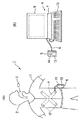
図1及び図2は本発明の第1の実施の形態に係り、図1は第1の実施の形態を備えたカプセル型内視鏡装置等の構成を示し、図2は第1の実施の形態のカプセル型内視鏡の構成を示す。
【0009】
図1(A)に示すように本発明の第1の実施の形態を備えた内視鏡検査を行うカプセル型内視鏡装置1は、患者2の口部から飲み込まれることにより体腔内管路を通過する際に体腔内管路内壁面を光学的に撮像した画像信号を無線で送信するカプセル型内視鏡3と、このカプセル型内視鏡3で送信された信号を患者2の体外に設けたアンテナユニット4により受け、画像を保存する機能を有する、(患者2の体外に配置される)体外ユニット5とから構成される。
【0010】
この体外ユニット5には、画像データを保存するために、容量が例えば1GBのコンパクトフラッシュ(R)サイズのハードディスクが内蔵されている。
そして、体外ユニット5に蓄積された画像データは検査中或いは検査終了後に図1(B)の表示システム6に接続して、画像を表示することができる。
【0011】
つまり、図1(B)に示すようにこの体外ユニット5は、表示システム6を構成するパーソナルコンピュータ(以下、パソコンと略記)7とUSBケーブル8等の通信を行う通信ケーブルで着脱自在に接続される。
【0012】
そして、パソコン7により体外ユニット5に保存した画像を取り込み、内部のハードディスクに保存したり、表示するため等の処理を行い表示部9により保存した画像を表示できるようにしている。このパソコン7にはデータ入力操作等を行う操作盤としての例えばキーボード10が接続されている。
【0013】
USBケーブル8としては、USB1.0、USB1.1、USB2のいずれの通信規格でも良い。また、この他にRS−232C、IEEE1394の規格のシリラルのデータ通信を行うものでも良いし、シリアルのデータ通信を行うものに限定されるものでなく、パラレルのデータ通信を行うものでも良い。
【0014】
図1(A)に示すようにカプセル型内視鏡3を飲み込んで内視鏡検査を行う場合には、患者2が着るシールド機能を持つシールドシャツ11の内側には複数のアンテナ12が取り付けられたアンテナユニット4が装着され、カプセル型内視鏡3により撮像され、それに内蔵されたアンテナから送信された信号を受け、このアンテナユニット4に接続された体外ユニット5に撮像した画像を保存するようにしている。この体外ユニット5は、例えば患者2のベルトに着脱自在のフックにより取り付けられる。
【0015】
また、この体外ユニット5は例えば箱形状であり、前面には画像表示を行う表示装置としての例えば液晶モニタ13と、制御操作を行う操作ボタン14とが設けてある。また、体外ユニット5の内部には、送受信回路(通信回路)、制御回路、画像データ表示回路、電源を備えている。
【0016】
図2に示すようにカプセル型内視鏡3は、筒状でその先端側をほぼ半球形状にした透明な前カバー16と、筒形状でその後端をほぼ半球形状にした後カバー17との後端及び前端を嵌合させてその内部に水密的な密閉構造のカプセル容器を形成し、その内部に対物光学系18等を収納している。
【0017】
前カバー16に対向する中央位置には、第1レンズ枠20と第2レンズ枠21とにそれぞれ第1レンズと第2レンズを取り付けて形成した対物光学系18が配置され、その結像位置には基板22の前面に取り付けたCMOSイメージャ23が配置されている。
また第1レンズ枠20に嵌合するようにして固定された基板2には白色LED25が取り付けられている。
【0018】
CMOSイメージャ23を取り付けた基板22は接続部26で駆動処理回路27を形成し、電気部品を実装した基板に電気的に接続されている。また、この駆動処理回路27を形成する基板の背面にはメモリ等を実装し、画像データを記憶する処理を行う記憶回路28を構成する基板が接続部29で接続するようにして配置されている。
【0019】
この記憶回路28を構成する基板の背面には無線通信を行う無線通信回路30を構成する基板が接続部31で接続するようにして配置されている。
【0020】
さらにこの無線通信回路30を構成する基板の背面にはボタン型の2つの電池32が配置されている。
また、駆動処理回路27を形成する基板に隣接する側部にはアンテナ33が配置され、無線通信回路30と接続されている。
【0021】
また、電池32は、例えばその負極が無線通信回路30等のグランドに接続され、無線通信回路30等の(正の)電源端にはバネ状接点部材35のリード部の一端と接続されている。
【0022】
このバネ状接点部材35は電池32の背面で接点部36aとなり、この接点部36aに近接するようにして電池32の正極に接続された他方の接点部36bが配置され、通常はその間に絶縁性のひも状部材37が介挿されて、OFFの状態に設定されている。
【0023】
この絶縁性のひも状部材37の一部は後カバー17に設けた弁部(或いはゴム栓部)38の小さな切り欠きを通して外部に露出し、この絶縁性のひも状部材37を引き抜くことにより接点部36a、36bは接触してONとなる。また、弁部38は閉じて水密を保持する。
【0024】
前カバー16におけるその前面となるドーム形状部分の内面及び外面は、その視野範囲(その範囲内の角度をθで示す)の周辺付近までは一定の曲率半径Ri及びRoに設定されている。本実施の形態では、例えばRi=6.0mm及びRo=6.5mmに設定されている。
【0025】
また、曲率半径Ri及びRoの中心位置が対物光学系18の入射瞳40の位置となるように設定されている。なお、本実施の形態では前カバー16の肉厚は均一にしている。
【0026】
また、視野範囲の周辺付近では、例えば外面の曲率半径Rpを曲率半径Ri及びRoより小さい値(具体的にはRp=4.0mm)に設定してその外径部分側と滑らかに繋ぐようにしている。なお、本実施の形態ではこのカプセル型内視鏡3の外径Dを11mmに設定している。
【0027】
また、第1のレンズ枠20の円錐形状の前面はその表面を粗面41等にすることにより反射防止する機能を持たせている。
また、本実施の形態では、視野範囲の角度θは例えば90°〜110°程度に設定されている。
【0028】
このように本実施の形態のカプセル型内視鏡3においては、図2に示すようにその前カバー16の前面側を略半球面形状にしているが、その場合対物光学系18の視野範囲の中心側の曲率半径(具体的には内面の曲率半径Ri、外面の曲率半径Ro)よりも、周辺側の曲率半径(具体的には外面の曲率半径Rp)を小さくしていることが特徴となっている。
【0029】
このような構成にすることにより、周辺側の曲率半径を中心側の曲率半径と同じにした場合よりも、カプセル型内視鏡3で内視鏡検査を行う場合に、カプセル型内視鏡3における前カバー16の視野中央部分が管腔臓器の粘膜等に密着してしまうのを防止ないしは軽減できるようにすると共に、カプセル型内視鏡3を小型化できるようにしている。
【0030】
次に本実施の形態の作用を説明する。
図1(A)で示すように口部からカプセル型内視鏡3を飲み込んで体腔内に挿入した場合、体腔内では図2に示すように体腔内の管腔臓器の粘膜42にはカプセル型内視鏡3の前カバー16における視野中心側よりも周辺部側が接触し易くなる。
【0031】
つまり、中心側の曲率半径は大きく、周辺部側の曲率半径が小さく屈曲しているので、より屈曲している周辺部側が粘膜42に接触し、中央部側は密着しないで観察できる観察視野を確保できる状態或いは広い観察可能範囲を持つようにできる。
【0032】
また、図2において、周辺側も中心側と同じ曲率半径にすると、外径が太くなって大型化してしまい、飲み込みにくくなったり、挿入(移動)性が低下する欠点が生じるが、本実施の形態の構造にすることにより、小さなサイズにして飲み込み性を向上できると共に、円滑な移動性等も確保できる。
【0033】
具体的に説明すると、図2の場合には外径D(=11mm)を、前カバー16の視野中心付近での外径の曲率半径Ro(=6.5mm)の2倍よりも小さくできる(これに対して、周辺側も中心側と同じ曲率半径にすると、外径Dは13mmになって、本実施の形態よりも太くなってしまう)。
【0034】
また、周辺側に対して中央側の曲率半径を大きくすること(その極端な場合として、図3に示すように曲率半径を無限大にした平面の場合がより分かり易い)により、中央部分の突出量を抑えることができ、全長を短くして飲み込み性を向上できる。
【0035】
従って、本実施の形態は以下の効果を有する。
外径や全長を小さくでき、飲み込み易くできると共に、広い観察視野を確保できる効果がある。
【0036】
(第2の実施の形態)
次に本発明の第2の実施の形態を図3を参照して説明する。図3は本発明の第2の実施の形態のカプセル型内視鏡51を示す。
このカプセル型内視鏡51は、筒状でその後端を丸くして閉塞した外装カバー52の前端に略半球形状の透明カバー53を嵌合させて接着等して、その内部を水密構造にし、対物光学系54等を収納している。
【0037】
透明カバー53に対向する中央位置には、第1レンズ枠55と第2レンズ枠56とにそれぞれ第1レンズと第2レンズを取り付けて形成した対物光学系54が配置され、その結像位置には基板57の前面に設けた凹部の平面部にCMOSイメージャ58が実装配置されている。
また、第1レンズ枠55に嵌合する第2レンズ枠56の筒部に(嵌合して接着剤等で)固定された基板60には、白色光を出射する白色LED61が複数取り付けられている。
【0038】
また、CMOSイメージャ58を取り付けた基板57の背面に駆動処理&記憶回路62を形成する基板が配置され、さらにその背面には無線通信回路63を構成する基板が配置されている。この基板の両面にはチップ部品64等が実装されている。
【0039】
この無線通信回路63を構成する基板の背面側にはボタン型の2つの電池32が配置されている。
また、駆動処理回路62を形成する基板に隣接する側部にアンテナ65が配置され、無線通信回路63と接続されている。
【0040】
また、電池32は、図2で説明した場合と同様にバネ状接点部材35と接続され、絶縁性のひも状部材37が介挿されて、OFFの状態に設定され、この絶縁性のひも状部材37を引き抜くことにより接点部36a、36bは接触してONとなり、弁部38は閉じて密閉状態を維持する。
【0041】
本実施の形態では透明カバー53のドーム形状部分の内面及び外面は、その視野範囲の周辺付近まではほぼ平面に近い形状(従って、その曲率半径RaはRa≒∞)に設定されている。なお、視野範囲は、例えば90°〜110°程度に設定されている。
【0042】
また、視野範囲θの境界付近から外側(周辺側)はその曲率半径Rp1或いはRp2に示すように中心側よりも小さな曲率半径にして滑らかに外径部分(の透明カバー53)に繋ぐようにしている。
【0043】
この場合の曲率半径Rp1或いはRp2としては、例えば1mm〜5mmの範囲内に設定されている。なお、本実施の形態でも透明カバー53の肉厚は均一にしている。
【0044】
また、本実施の形態では、図3に示すように視野範囲内では2点鎖線で示す部分の内側部分がピントが合わないピンボケ部分となり、これより外側がピントが合う部分となる。
【0045】
図3では光軸上では対物光学系54の第1レンズの前面から距離a+b部分がピンボケ部分となり、これより遠距離側がピントが合う部分となる。
【0046】
この場合、対物光学系54の第1レンズの前面の光軸上の位置をYとし、その光軸上前方で透明カバー53の外表面の位置をXとすると、その間の距離をbで、この位置Xと2点鎖線で曲面までの距離をaで示している。
【0047】
そして、このように透明カバー53の視野の中心側を平面状にすることにより、中心部分での突出量を抑制でき、カプセル型内視鏡51の全長を短くできる。従って、飲み込み性を向上できる。
【0048】
また、中心側を平面形状にすることにより、中央側が粘膜42に接触しにくくでき、視野を確保できる。この場合、透明カバー53の外面の位置ではピントが合わないが、実質的には支障ない(突出量を抑えた分、全長を短くできる利点がある)。
【0049】
(第3の実施の形態)
次に本発明の第3の実施の形態を図4ないし図6を参照して説明する。図4は第3の実施の形態のカプセル型内視鏡を示し、図5は対物光学系の構成例を示し、図6は図5の場合における収差図を示す。
【0050】
図4に示すカプセル型内視鏡71は、円筒形状でその後端を半球状に丸くして閉塞した外装ケース72の先端側となる開口する端部に半球面形状の透明カバー73を水密的に接続固定してその内側を密閉し、その密閉したカプセル状容器内に以下の内蔵物を収納している。
【0051】
透明カバー73に対向する中央部には、レンズ枠75に取り付けられた対物光学系76が配置され、その結像位置にはカバーレンズ77で保護されたCMOSイメージャ78が配置されている。このCMOSイメージャ78は例えば基板79の前面に実装されている。なお、CMOSイメージャ78の代わりにCCDでも良い。
また、対物光学系76は2枚の凸平レンズで構成され、その後レンズとなる凸平レンズの後面をカバーガラス77に接着して固定されている。そして、ピント出しを行う場合には、後レンズに対してその外径に嵌合する内径のレンズ枠75側を光軸O方向に移動して調整し、調整後には接着剤などで固定される。
【0052】
また、レンズ枠75には白色LED80を取り付けた基板81がその中央に設けた孔をレンズ枠75に嵌合させて固定されている。この基板81はチップ部品が実装されており、白色LED80を間欠的にフラッシュ発光させるように駆動する駆動回路を形成している。
【0053】
また、CMOSイメージャ78を取り付けた基板79の背面には、基板79とでCMOSイメージャ78を駆動すると共に、出力信号に対する処理を行う駆動&処理回路82を構成する基板が配置されている。
【0054】
この駆動&処理回路82を構成する基板の背面には画像信号を無線で行う処理をする無線回路83を構成する基板が配置され、この無線回路83を構成する基板の背面にはボタン型の電池84が配置されている。
【0055】
また、このボタン型の電池84の背面側でカプセル状容器の後端となる内側には電源のONを外部から行うスイッチ85が収納されている。
また、無線回路83の側面に隣接してアンテナ86が配置されている。
【0056】
本実施の形態では、対物光学系76による光学特性を図4に示すように設定している。
つまり、この対物光学系76の被写界深度の近点位置を視野範囲(その範囲内の角度をθで示す)の視野中心側部分に対して、視野周辺部分側ではより近くなるように設定している。
【0057】
具体的には、図4に示すように光軸Oに沿った方向では対物光学系76の第1レンズ面の前から距離aまでがぼける範囲で、その距離aより遠方側の距離範囲Laがピントが合う被写界深度に設定され、また視野範囲の境界では対物光学系76の第1レンズ面の前から距離bまでがぼける範囲で、その距離bより遠方側の距離範囲Lbがピントが合う被写界深度に設定されている。
【0058】
つまり、光軸O上ではaが被写界深度の近点であり、視野境界部分ではbが被写界深度の近点であり、この場合にはa>bに設定され、またLa>Lbに設定されている。この場合の具体例としては、a=10mmで、La=10mm〜40mm、b=5.5mmでLb=5.5mm〜20mmである。なお、図4においては、ぼける範囲を斜線部分で示している。
【0059】
図4に示す対物光学系76の第1レンズ及び第2レンズは例えば図5(A)に拡大して示すように径の小さい凸平レンズ87aと、それより径が大きい凸平レンズ87bとから構成され、第1レンズ87aの前面には明るさ絞り88が配置されている。
そして、これらの第1レンズ及び第2レンズにより、CMOSイメージャ78の撮像面に像を結ぶ。
【0060】
この場合、レンズ設計の際には例えば撮像面が図5(A)の2点鎖線で示すようにレンズ側に中央部が凹となるような湾曲した撮像面を考えて、この湾曲した撮像面に結像するように設計する。
【0061】
このように設計することにより、実際には撮像面は光軸Oと垂直となっているので、光軸Oに近い部分の撮像面に結像する領域では湾曲しない場合とほぼ同様の撮像面となるので、この領域でピントが合った状態で結像した場合には、周辺側ではより近距離側に設定された物体に対してピントが合う状態となる。
【0062】
図5(A)に示した対物光学系76で、視野角を90°に設定した場合における収差図を図6(A)に示す。図6(A)において、横軸は近軸の結像位置からの距離を符号を含めて示し、縦軸は像の高さを示す。この収差図から実線で示すサジタル像面sでの収差とメリジオナル像面mの収差の中間の1点鎖線で示す曲線がベスト像面の収差となる。
【0063】
図5(A)の光学系の場合には、視野角が90°を越えると収差が急激に大きくなるため、より大きな視野角の場合には、図5(B)に示すような光学系に設定することが望ましい。
【0064】
図5(B)では図5(A)における第1レンズとして(ミニ)メニスカスレンズ87cを採用している。このメニスカスレンズ87cは前面側が比較的大きな曲率半径で凹面となり、全体としては凸パワーのレンズ機能(特性)を示す。
【0065】
この光学系を用いて例えば120°の視野角に設定した場合の収差図を図6(B)に示す。この場合には、視野角を大きくした場合にも、その収差が大きくなるのを軽減できる。
【0066】
このように設定した背景等を補足説明すると以下のようになる。
従来の内視鏡のように、体腔内に挿入された撮像部と、体外にあって撮像部の視野方向を制御する操作部がつながっている場合には、視野方向を観察者の意図した方向に自在に調節できるので、観察対象が常に視野内の観察しやすい位置にあるように調整して観察することができる。このため撮像部に用いられる対物光学系には、画角の小さい視野の中心付近から画角の大きい視野の周辺まで諸収差を良好に補正されたものが用いられる。
【0067】
これに対し、カプセル型内視鏡では、撮像部の視野方向を自在に制御することは難しい。このため、観察対象が視野の中心付近にあっても、視野の周辺部にあっても常にピントのあった観察画像が得られることが望ましい。
【0068】
例えば管腔状の内壁部分を観察する場合には、観察対象となる前記内壁部分は視野の周辺に位置することが多い。また、前記撮像部の前方には曲面で構成された透明カバーが設けられており、前記内壁部分と前記透明カバーの外面が密着した状態で観察が行われる場合が想定される。このとき、視野の周辺部では少なくとも前記透明カバーの外面でピントが合っている必要があるが、視野中心付近ではピントがあっている必要はない。
【0069】
そこで、本実施の形態のカプセル型内視鏡71の撮像部に用いられる対物光学系76は、この対物光学系76を故意に像面湾曲が発生するレンズ構成とし、視野中心付近のピント位置と視野の周辺でのピント位置をずらすように設計したことを特徴としている。
【0070】
この対物光学系76を、凸パワーをもった2枚のレンズで構成すると、ペッツバール和が大きくなり、画角の大きい視野周辺での結像位置を近軸の結像位置に比べて被写体側に大きく傾けることができる。ここで、撮像面は光軸Oに対して垂直に配置されるから、前記撮像面を前記近軸の結像位置に置けば、視野周辺部分でのピント位置と視野中心付近のピント位置をずらすことができる。
【0071】
図5(A)は2枚の平凸レンズ87a、87bで構成され、50°〜110°程度の視野角をもつ対物光学系76の非点収差の発生状況を示した収差図の1例であり、縦軸は像の高さ、横軸は近軸の結像位置からの距離を表している。
【0072】
この対物光学系76のメリジオナル面内の屈折力とサジタル面内の屈折力の差によって、サジタル像面sとメリジオナル像面mには非点格差が生じる。この例ではサジタル像面sがメリジオナル像面mに比べて負の側に大きく傾いており、この結果、サジタル像面sとメリジオナル像面mのほぼ中間に位置するベスト像面も負の側に傾いている。
【0073】
また、カプセル型内視鏡71においては、対物光学系76の視野を広角化して、できるだけ広い範囲をもれなく観察できるようにするのが好ましい。この場合、前記対物光学系76に求められる視野角は90°〜140°になる。このように広角な対物光学系76を上記のように平凸レンズ2枚で構成すると、画角の大きい視野周辺での非点格差が急激に増大してしまい、ベスト像面が傾きすぎたり画質が劣化する不具合が生じる。
【0074】
上記不具合に対応するために、図5(B)に示すような凸パワーを持ったメニスカスレンズ87cと平凸レンズ87bからなる対物光学系76を用いる。
また図6(B)にはメニスカスレンズ87cと平凸レンズ87bとからなる視野角120°の対物光学系76の収差図を示した。
【0075】
この対物光学系76では第1レンズ87cに凹面を設けて他の凸面で発生する非点収差を適宜補正し、像面の傾きをコントロールしたことを特徴とするものであり、広角な視野を有しながら適度な像面湾曲をもち、しかも画像劣化のない光学系を実現できる点で、カプセル型内視鏡71に最適な構成であることが分かる。
【0076】
メニスカスレンズ87cは平凸レンズ87bに比べて加工性が悪くなるが、光学プラスチックを所望の形状に射出成型することで、加工性を大幅に改善することができる。
また、平凸レンズ87bも同様に光学プラスチックを射出成型すれば加工コストの安い対物光学系76を実現できる。
【0077】
本実施の形態によれば、視野中央側では遠方側にピントが合い、一方視野の周辺側では近距離側にピントが合って、体腔内における管腔形状部分を通過させて画像を得る場合の内視鏡検査に適したカプセル型内視鏡を実現できる。
【0078】
(第4の実施の形態)
次に本発明の第4の実施の形態を図7を参照して説明する。図7は第4の実施の形態のカプセル型内視鏡91を示す。
このカプセル型内視鏡91は例えば第1の実施の形態とほぼ同様な構成にして、その対物光学系18の代わりに特性が異なる対物光学系92を採用することにより、その特性を第3の実施の形態と同様にその対物光学系92の被写界深度の近点位置を視野中心部分に対して、視野周辺部分を近くに設定している。
【0079】
つまり、この対物光学系92は視野範囲内における視野中心側では、第3の実施の形態で説明したようにその被写界深度の範囲を遠距離側(遠距離寄り)に設定し、視野周辺側ではその被写界深度の範囲を近距離側(近距離寄り)に設定している。
【0080】
具体的には、図7に示すように光軸Oに沿った方向では対物光学系92の第1レンズ面の前から距離aまでがぼける範囲で、その距離aより遠方側の距離範囲Laがピントが合う被写界深度に設定され、また視野範囲の境界では対物光学系92の第1レンズ面の前から距離bまでがぼける範囲で、その距離bより遠方側の距離範囲Lbがピントが合う被写界深度に設定されている。
【0081】
つまり、光軸O上ではaが被写界深度の近点であり、視野境界部分ではbが被写界深度の近点であり、この場合にはa>bに設定され、またLa>Lbに設定されている。本実施の形態の場合の具体例としては、a=8mmで、La=8mm〜30mm、b=6mmでLb=6mm〜25mmである。なお、図7においては、ぼける範囲を斜線部分で示している。
【0082】
また、本実施の形態では、前カバー16におけるその前面となるドーム形状部分の内面及び外面は、その視野範囲(その範囲内の角度をθで示す)の周辺付近までは一定の曲率半径Ri及びRoに設定されている。
【0083】
本実施の形態では、例えばRi=6.0mm及びRo=6.5mmに設定されている。また、視野周辺からそれより外側にかけては前カバーのドーム形状部分の曲率半径Ri、Roより小さい曲率半径、例えばRp=4mmで外径部分側と滑らかに繋ぐようにしている。
【0084】
このようにすることにより、第3の実施の形態と同様に管腔部分を観察するのに適した効果を有すると共に、第1或いは第2の実施の形態のように前カバー16におけるそのドーム形状部分の中心付近での突出量を抑制してカプセル全長を短いサイズにでき、良好な飲み込み性等を確保できる。
【0085】
[付記]
4.請求項1において、前記対物光学系の被写界深度の近点位置を視野中心部分に対して、視野周辺部分を近くに設定した。
5.生体内を照明する照明手段と、該照明手段によって照明された部位を撮像する撮像手段と、該撮像手段前方の対物光学系と、該対物光学系前方の透明カバーと、を密閉カプセルに内蔵したカプセル型内視鏡において、
前記対物光学系の被写界深度の近点位置を視野中心部分に対して、視野周辺部分を近くに設定したことを特徴とするカプセル型内視鏡。
【0086】
6.付記5において、さらに前記撮像手段が撮像し、出力した画像信号を体外に送信する送信手段を有する。
7.付記5において、該対物光学系は凸レンズ又は凸平レンズの組み合わせにより構成した。
8.付記5において、該対物光学系は凸パワーを持ったメニスカスレンズと凸平レンズの組み合わせにより構成した。
9.付記7、8において、レンズは光学プラスチックを射出成型した。
【0087】
(付記5〜8の背景)
従来例として、特開2001−91860とPCTWO 01/65995 A2とがある。
(従来技術の概要と不具合)
前者は、略半球状の透明カバー内に対物レンズと照明体を固定したものであり、対物レンズは凹レンズと凸レンズを組み合わせた構成であり、対物光学系の被写界深度に関しては何ら開示されていない。また、略半球状の透明カバーの視野中心部分と視野周辺部分の曲率半径が同じものであった。このため、管腔臓器の粘膜が透明カバーの中心部分まで密着しやすいという不具合があり、また、略半球状の中心から周辺まで同じ曲率の透明カバーの場合は、透明カバーに繋がるカプセル外径によって曲率半径が決まるので外径が太い時には全長が長くなるという不具合もあった。
【0088】
また後者は撮像手段としてCMOSを使ったもので、対物レンズは凸凸レンズ1個で構成されているものであり、前者と同じく対物光学系の被写界深度に関しては何ら開示されていない。前者と同じ不具合があった。
(付記5〜8の目的)
簡単な構成で、カプセルの全長を長くすることなく、視野中心から周辺まで良好な画像を得ることができるカプセル型内視鏡を提供することを目的とする。 また、透明カバーの視野周辺部分は、視野中心部分に対して、体腔内で管腔臓器の粘膜が密着しやすいので、近点寄りに設定でき、これに対して、視野中心部分は視野周辺部分に比べて管腔臓器の奥まで見えるように周辺よりは遠点寄りに設定できるものを提供することを目的とする。そのため、付記5〜8の構成にした。
【0089】
以上説明したように本発明によれば、中心部分での突出量を抑制できて全長を短くして飲み込み性を向上でき、また中央部分を体腔内粘膜に接触しにくくして視野を確保できる効果を有する。
【図面の簡単な説明】
【図1】本発明の第1の実施の形態を備えたカプセル型内視鏡装置等の構成を示す図。
【図2】第1の実施の形態のカプセル型内視鏡の内部構成を示す断面図。
【図3】本発明の第2の実施の形態のカプセル型内視鏡の内部構成を示す断面図。
【図4】本発明の第3の実施の形態のカプセル型内視鏡を示す断面図。
【図5】対物光学系の構成例を示す図。
【図6】図5の場合における収差図。
【図7】本発明の第4の実施の形態のカプセル型内視鏡の内部構成を示す断面図。
【符号の説明】
1…カプセル型内視鏡装置
2…患者
3…カプセル型内視鏡
4…アンテナユニット
5…体外ユニット
6…表示システム
7…パソコン
8…USBケーブル
11…シールドシャツ
12…アンテナ
13…液晶モニタ
16…前カバー
17…後カバー
18…対物光学系
20、21…レンズ枠
23…CMOSイメージャ
25…白色LED
27…駆動処理回路
28…記憶回路
30…無線通信回路
32…電池
33…アンテナ
40…入射瞳
41…粗面[0001]
BACKGROUND OF THE INVENTION
The present invention relates to a swallowable capsule endoscope that inspects a living body.
[0002]
[Prior art]
In recent years, endoscopes have been widely adopted in the medical field and the industrial field. In recent years, the medical field has been able to reduce the pain of insertion due to insertion by a patient swallowing a capsule-type capsule endoscope without the need for an insertion part in an endoscope. The situation is now in use.
For example, there are JP 2001-91860 A and PCT application WO 01/65995 A2.
[0003]
In the former conventional example, an objective lens and an illuminating means using a light emitting diode provided symmetrically so as to sandwich the objective lens are incorporated inside a substantially hemispherical transparent cover, and an object illuminated by the light emitting diode becomes an observation range. The portion is imaged on the image sensor by the objective lens.
The latter conventional example has almost the same configuration.
[0004]
[Problems to be solved by the invention]
In these conventional examples, the objective lens and the illuminator are fixed in a substantially hemispherical transparent cover, and the curvature radius of the central part of the visual field and the peripheral part of the visual field are the same. There was a problem that it was easy to adhere to the center of the cover.
[0005]
In addition, in the case of a transparent cover having the same curvature from the center to the periphery of a substantially hemispherical shape, the curvature radius is determined by the outer diameter of the capsule connected to the transparent cover.
[0006]
(Object of invention)
The present invention has been made in view of the above points, and can suppress the amount of protrusion at the central portion, shorten the overall length, improve swallowability, and make the central portion difficult to contact the mucous membrane in the body cavity. An object of the present invention is to provide a capsule endoscope that can ensure the above.
[0007]
[Means for Solving the Problems]
A capsule endoscope according to an aspect of the present invention includes an illuminating unit that illuminates a living body, an imaging unit that images a portion illuminated by the illuminating unit, an objective optical system in front of the imaging unit, In a sealed capsule, and a transparent cover constituting at least a part of the capsule is arranged in front of the objective optical system In the capsule endoscope
A portion from the center of the visual field range of the objective optical system to the vicinity of the periphery of the transparent cover is made substantially parallel to the outer surface of the objective optical system, and the radius of curvature outside the boundary of the visual field range is larger than the center side. It comprised so that it might become small.
[0008]
DETAILED DESCRIPTION OF THE INVENTION
Embodiments of the present invention will be described below with reference to the drawings.
(First embodiment)
1 and 2 relate to a first embodiment of the present invention. FIG. 1 shows the configuration of a capsule endoscope apparatus or the like provided with the first embodiment, and FIG. 2 shows the first embodiment. The structure of the capsule endoscope of a form is shown.
[0009]
As shown in FIG. 1 (A), a capsule endoscope apparatus 1 for performing an endoscopic examination provided with the first embodiment of the present invention is infused from the mouth of a
[0010]
The
The image data stored in the
[0011]
That is, as shown in FIG. 1B, the
[0012]
Then, the image stored in the
[0013]
The USB cable 8 may be any communication standard of USB1.0, USB1.1, and USB2. In addition to this, serial data communication of RS-232C and IEEE 1394 standards may be performed, and the present invention is not limited to serial data communication, and may be parallel data communication.
[0014]
As shown in FIG. 1A, when performing an endoscopic examination by swallowing the
[0015]
The
[0016]
As shown in FIG. 2, the
[0017]
An objective
A
[0018]
The
[0019]
A substrate constituting the
[0020]
Further, two button-
An
[0021]
The
[0022]
The spring-
[0023]
A part of the insulating string-
[0024]
The inner surface and the outer surface of the dome-shaped portion that is the front surface of the
[0025]
Further, the center positions of the curvature radii Ri and Ro are set to be the position of the
[0026]
Further, in the vicinity of the periphery of the visual field range, for example, the curvature radius Rp of the outer surface is set to a value smaller than the curvature radii Ri and Ro (specifically, Rp = 4.0 mm) so as to smoothly connect to the outer diameter portion side. ing. In the present embodiment, the outer diameter D of the
[0027]
Further, the conical front surface of the
In the present embodiment, the angle θ of the visual field range is set to about 90 ° to 110 °, for example.
[0028]
As described above, in the
[0029]
By adopting such a configuration, the
[0030]
Next, the operation of this embodiment will be described.
As shown in FIG. 1A, when the
[0031]
That is, since the radius of curvature on the center side is large and the radius of curvature on the peripheral side is small and bent, an observation field of view that can be observed without contact with the
[0032]
Further, in FIG. 2, if the peripheral side has the same radius of curvature as the central side, the outer diameter becomes thick and the size increases, which makes it difficult to swallow and lowers insertion (movability). By adopting the structure of the form, it is possible to improve the swallowability by reducing the size, and to ensure smooth mobility and the like.
[0033]
Specifically, in the case of FIG. 2, the outer diameter D (= 11 mm) can be made smaller than twice the radius of curvature Ro (= 6.5 mm) of the outer diameter near the center of the field of view of the front cover 16 ( On the other hand, if the peripheral side has the same radius of curvature as the central side, the outer diameter D becomes 13 mm, which is thicker than in the present embodiment.
[0034]
Further, by increasing the radius of curvature on the center side with respect to the peripheral side (as an extreme case, it is easier to understand the case of a plane having an infinite radius of curvature as shown in FIG. 3), so that the center portion protrudes. The amount can be reduced, and the overall length can be shortened to improve swallowability.
[0035]
Therefore, this embodiment has the following effects.
The outer diameter and overall length can be reduced, the swallowing can be facilitated, and a wide observation field of view can be secured.
[0036]
(Second Embodiment)
Next, a second embodiment of the present invention will be described with reference to FIG. FIG. 3 shows a
The
[0037]
An objective
In addition, a plurality of
[0038]
Further, a substrate for forming the drive processing &
[0039]
Two button-
In addition, an
[0040]
Further, the
[0041]
In the present embodiment, the inner surface and the outer surface of the dome-shaped portion of the
[0042]
Further, from the vicinity of the boundary of the visual field range θ to the outside (peripheral side), as shown by the curvature radius Rp1 or Rp2, the curvature radius is smaller than that of the center side so as to be smoothly connected to the outer diameter portion (the transparent cover 53). Yes.
[0043]
In this case, the curvature radius Rp1 or Rp2 is set, for example, within a range of 1 mm to 5 mm. Note that the thickness of the
[0044]
In the present embodiment, as shown in FIG. 3, the inner portion of the portion indicated by the two-dot chain line is the out-of-focus portion within the field of view, and the outer portion is the portion in focus.
[0045]
In FIG. 3, on the optical axis, the distance a + b from the front surface of the first lens of the objective
[0046]
In this case, if the position on the optical axis of the front surface of the first lens of the objective
[0047]
And by making the center side of the visual field of the
[0048]
Moreover, by making the center side into a planar shape, the center side can hardly contact the
[0049]
(Third embodiment)
Next, a third embodiment of the present invention will be described with reference to FIGS. FIG. 4 shows a capsule endoscope according to the third embodiment, FIG. 5 shows a configuration example of the objective optical system, and FIG. 6 shows aberration diagrams in the case of FIG.
[0050]
A
[0051]
An objective
The objective
[0052]
Further, a
[0053]
Further, on the back surface of the
[0054]
A substrate constituting a
[0055]
In addition, a
An
[0056]
In the present embodiment, the optical characteristics of the objective
That is, the near point position of the depth of field of the objective
[0057]
Specifically, as shown in FIG. 4, in the direction along the optical axis O, the distance range La on the far side from the distance a is a range in which the distance a is deviated from the front of the first lens surface of the objective
[0058]
That is, a is the near point of the depth of field on the optical axis O, and b is the near point of the depth of field at the field boundary portion. In this case, a> b is set, and La> Lb. Is set to As a specific example in this case, a = 10 mm, La = 10 mm to 40 mm, b = 5.5 mm, and Lb = 5.5 mm to 20 mm. In FIG. 4, the blurred range is indicated by the hatched portion.
[0059]
The first lens and the second lens of the objective
Then, an image is formed on the imaging surface of the
[0060]
In this case, when designing the lens, for example, consider a curved imaging surface having a concave central portion on the lens side as indicated by a two-dot chain line in FIG. Designed to form an image.
[0061]
By designing in this way, the imaging surface is actually perpendicular to the optical axis O. Therefore, the imaging surface is almost the same as when the image is not curved in the region where the imaging surface near the optical axis O is imaged. Therefore, when an image is formed in a focused state in this region, the peripheral side is in a focused state with respect to an object set closer to the short distance side.
[0062]
FIG. 6 (A) shows aberration diagrams when the viewing angle is set to 90 ° in the objective
[0063]
In the case of the optical system in FIG. 5A, the aberration increases rapidly when the viewing angle exceeds 90 °. Therefore, in the case of a larger viewing angle, the optical system as shown in FIG. It is desirable to set.
[0064]
In FIG. 5B, a (mini)
[0065]
FIG. 6B shows an aberration diagram when the viewing angle is set to 120 °, for example, using this optical system. In this case, even when the viewing angle is increased, the increase in the aberration can be reduced.
[0066]
A supplementary explanation of the background set in this way is as follows.
When the imaging unit inserted into the body cavity and the operation unit that controls the visual field direction of the imaging unit are connected outside the body like a conventional endoscope, the visual field direction is the direction intended by the observer Therefore, the observation object can be adjusted and observed so that the observation target is always in a position where it can be easily observed in the visual field. For this reason, an objective optical system used in the image pickup unit is one in which various aberrations are favorably corrected from the vicinity of the center of the field of view with a small field angle to the periphery of the field of view with a large field angle.
[0067]
On the other hand, in the capsule endoscope, it is difficult to freely control the viewing direction of the imaging unit. For this reason, it is desirable to always obtain a focused observation image regardless of whether the observation target is near the center of the visual field or the peripheral part of the visual field.
[0068]
For example, when observing a lumen-like inner wall portion, the inner wall portion to be observed is often located around the visual field. In addition, a transparent cover formed of a curved surface is provided in front of the imaging unit, and it is assumed that observation is performed in a state where the inner wall portion and the outer surface of the transparent cover are in close contact with each other. At this time, it is necessary to focus at least on the outer surface of the transparent cover in the peripheral portion of the visual field, but it is not necessary to focus in the vicinity of the center of the visual field.
[0069]
Therefore, the objective
[0070]
If this objective
[0071]
FIG. 5A is an example of an aberration diagram showing the occurrence of astigmatism in the objective
[0072]
Due to the difference between the refractive power in the meridional plane and the refractive power in the sagittal plane of the objective
[0073]
In the
[0074]
In order to deal with the above problem, an objective
FIG. 6B shows an aberration diagram of the objective
[0075]
This objective
[0076]
The
Similarly, the plano-
[0077]
According to the present embodiment, when the center of the visual field is focused on the far side, while the peripheral side of the visual field is focused on the short distance side, the image is obtained by passing through the lumen-shaped part in the body cavity. A capsule endoscope suitable for endoscopy can be realized.
[0078]
(Fourth embodiment)
Next, a fourth embodiment of the present invention will be described with reference to FIG. FIG. 7 shows a
The
[0079]
That is, the objective
[0080]
Specifically, as shown in FIG. 7, in the direction along the optical axis O, the distance range La on the far side from the distance a is a range in which the distance from the front of the first lens surface of the objective
[0081]
That is, a is the near point of the depth of field on the optical axis O, and b is the near point of the depth of field at the field boundary portion. In this case, a> b is set, and La> Lb. Is set to As a specific example in the present embodiment, a = 8 mm, La = 8 mm to 30 mm, b = 6 mm, and Lb = 6 mm to 25 mm. In FIG. 7, the blurred range is indicated by the hatched portion.
[0082]
Further, in the present embodiment, the inner surface and the outer surface of the dome-shaped portion that is the front surface of the
[0083]
In the present embodiment, for example, Ri = 6.0 mm and Ro = 6.5 mm are set. Further, from the periphery of the visual field to the outside, the curvature radius Ri, Ro of the front cover is smaller than that of the dome-shaped portion, for example, Rp = 4 mm, and is smoothly connected to the outer diameter portion side.
[0084]
By doing in this way, it has an effect suitable for observing the lumen part as in the third embodiment, and the dome shape in the
[0085]
[Appendix]
4). In claim 1, the near point position of the depth of field of the objective optical system is set near the visual field center part and the visual field peripheral part is set close.
5). A sealed capsule includes an illuminating unit that illuminates the inside of the living body, an imaging unit that images a portion illuminated by the illuminating unit, an objective optical system in front of the imaging unit, and a transparent cover in front of the objective optical system. In a capsule endoscope,
A capsule endoscope characterized in that a near point position of a depth of field of the objective optical system is set close to a center portion of a field of view and a peripheral portion of the field of view is set close.
[0086]
6). In
7). In
8). In
9. In appendices 7 and 8, the optical plastic was injection molded for the lens.
[0087]
(Background of Appendix 5-8)
Conventional examples include JP-A-2001-91860 and PCTWO 01/65995 A2.
(Overview of conventional technology and problems)
In the former, an objective lens and an illuminating body are fixed in a substantially hemispherical transparent cover. The objective lens has a configuration in which a concave lens and a convex lens are combined. Nothing is disclosed regarding the depth of field of the objective optical system. Absent. Moreover, the curvature radius of the visual field center part and visual field periphery part of the substantially hemispherical transparent cover was the same. For this reason, there is a problem that the mucous membrane of the luminal organ tends to adhere to the central part of the transparent cover, and in the case of a transparent cover with the same curvature from the center to the periphery of the substantially hemispherical, Since the radius of curvature is determined, there is a problem that the total length becomes long when the outer diameter is large.
[0088]
The latter uses CMOS as an imaging means, and the objective lens is composed of one convex lens, and no depth of field of the objective optical system is disclosed as in the former. There was the same problem as the former.
(Purpose of appendices 5-8)
An object of the present invention is to provide a capsule endoscope that can obtain a good image from the center of the visual field to the periphery with a simple configuration without increasing the total length of the capsule. In addition, the peripheral part of the visual field of the transparent cover can be set closer to the near point because the mucous membrane of the luminal organ easily adheres to the central part of the visual field in the body cavity, whereas the central part of the visual field is the peripheral part of the visual field It is an object of the present invention to provide a device that can be set closer to a far point than the periphery so that it can be seen deep inside the hollow organ. Therefore, it was set as the structure of appendixes 5-8.
[0089]
As described above, according to the present invention, The amount of protrusion at the central part can be suppressed, the overall length can be shortened to improve swallowing, and the central part can be made difficult to contact the mucous membrane in the body cavity to secure a visual field. Has an effect.
[Brief description of the drawings]
FIG. 1 is a diagram showing a configuration of a capsule endoscope apparatus or the like provided with a first embodiment of the present invention.
FIG. 2 is a cross-sectional view showing an internal configuration of the capsule endoscope according to the first embodiment.
FIG. 3 is a cross-sectional view showing an internal configuration of a capsule endoscope according to a second embodiment of the present invention.
FIG. 4 is a cross-sectional view showing a capsule endoscope according to a third embodiment of the present invention.
FIG. 5 is a diagram illustrating a configuration example of an objective optical system.
FIG. 6 is an aberration diagram in the case of FIG. 5;
FIG. 7 is a cross-sectional view showing an internal configuration of a capsule endoscope according to a fourth embodiment of the present invention.
[Explanation of symbols]
1 ... Capsule endoscope device
2 ... Patient
3 ... Capsule endoscope
4 ... Antenna unit
5 ... Extracorporeal unit
6 ... Display system
7 ... PC
8 ... USB cable
11 ... Shield shirt
12 ... Antenna
13 ... LCD monitor
16 ... Front cover
17 ... Rear cover
18 ... Objective optical system
20, 21 ... Lens frame
23 ... CMOS imager
25 ... White LED
27 ... Drive processing circuit
28: Memory circuit
30. Wireless communication circuit
32 ... Battery
33 ... Antenna
40 ... Entrance pupil
41 ... rough surface
Claims (5)
前記透明カバーの前記対物光学系の視野範囲の中心から周辺付近までの部分を該対物光学系の外表面と略平行にして、前記視野範囲の境界付近から外側の曲率半径を中心側よりも小さくなるように構成したことを特徴とするカプセル型内視鏡。An illuminating means for illuminating the inside of the living body, an imaging means for imaging the portion illuminated by the illuminating means, and an objective optical system in front of the imaging means are incorporated in a sealed capsule, and the front in front of the objective optical system In a capsule endoscope in which a transparent cover constituting at least a part of a capsule is arranged ,
The portion of the transparent cover from the center of the visual field range of the objective optical system to the vicinity thereof is made substantially parallel to the outer surface of the objective optical system, and the radius of curvature outside the boundary of the visual field range is smaller than the central side. A capsule endoscope characterized by being configured as described above.
Priority Applications (3)
| Application Number | Priority Date | Filing Date | Title |
|---|---|---|---|
| JP2002064018A JP3895618B2 (en) | 2002-03-08 | 2002-03-08 | Capsule endoscope |
| US10/347,325 US6939295B2 (en) | 2002-03-08 | 2003-01-21 | Capsule endoscope |
| US11/200,129 US7244229B2 (en) | 2002-03-08 | 2005-08-10 | Capsule endoscope |
Applications Claiming Priority (1)
| Application Number | Priority Date | Filing Date | Title |
|---|---|---|---|
| JP2002064018A JP3895618B2 (en) | 2002-03-08 | 2002-03-08 | Capsule endoscope |
Publications (3)
| Publication Number | Publication Date |
|---|---|
| JP2003260024A JP2003260024A (en) | 2003-09-16 |
| JP2003260024A5 JP2003260024A5 (en) | 2005-09-02 |
| JP3895618B2 true JP3895618B2 (en) | 2007-03-22 |
Family
ID=28670974
Family Applications (1)
| Application Number | Title | Priority Date | Filing Date |
|---|---|---|---|
| JP2002064018A Expired - Fee Related JP3895618B2 (en) | 2002-03-08 | 2002-03-08 | Capsule endoscope |
Country Status (2)
| Country | Link |
|---|---|
| US (2) | US6939295B2 (en) |
| JP (1) | JP3895618B2 (en) |
Families Citing this family (84)
| Publication number | Priority date | Publication date | Assignee | Title |
|---|---|---|---|---|
| US7813789B2 (en) * | 1999-06-15 | 2010-10-12 | Given Imaging Ltd. | In-vivo imaging device, optical system and method |
| US7996067B2 (en) * | 1999-06-15 | 2011-08-09 | Given Imaging Ltd. | In-vivo imaging device, optical system and method |
| IL130486A (en) * | 1999-06-15 | 2005-08-31 | Given Imaging Ltd | Optical system |
| IL143259A (en) | 2001-05-20 | 2006-08-01 | Given Imaging Ltd | Method for moving an object through the colon |
| US7727169B1 (en) | 2001-06-11 | 2010-06-01 | Given Imaging, Ltd. | Device for in vivo sensing |
| EP1418833B1 (en) | 2001-06-18 | 2008-08-13 | Given Imaging Ltd. | Swallowable in vivo sensing capsule with a circuit board having rigid sections and flexible sections |
| EP1428178A4 (en) * | 2001-09-05 | 2009-01-14 | Given Imaging Ltd | System and method for three dimensional display of body lumens |
| US8428685B2 (en) * | 2001-09-05 | 2013-04-23 | Given Imaging Ltd. | System and method for magnetically maneuvering an in vivo device |
| US20030174208A1 (en) * | 2001-12-18 | 2003-09-18 | Arkady Glukhovsky | Device, system and method for capturing in-vivo images with three-dimensional aspects |
| US6958034B2 (en) * | 2002-02-11 | 2005-10-25 | Given Imaging Ltd. | Self propelled device |
| US6939290B2 (en) * | 2002-02-11 | 2005-09-06 | Given Imaging Ltd | Self propelled device having a magnetohydrodynamic propulsion system |
| JP4363843B2 (en) * | 2002-03-08 | 2009-11-11 | オリンパス株式会社 | Capsule endoscope |
| US7662094B2 (en) | 2002-05-14 | 2010-02-16 | Given Imaging Ltd. | Optical head assembly with dome, and device for use thereof |
| JP2005525896A (en) | 2002-05-16 | 2005-09-02 | シー2キュア インコーポレイティド | Small camera head |
| US7473218B2 (en) * | 2002-08-06 | 2009-01-06 | Olympus Corporation | Assembling method of capsule medical apparatus |
| AU2003249551A1 (en) * | 2002-08-13 | 2004-02-25 | Given Imaging Ltd. | System for in vivo sampling and analysis |
| US7662093B2 (en) * | 2002-09-30 | 2010-02-16 | Given Imaging, Ltd. | Reduced size imaging device |
| US8449452B2 (en) * | 2002-09-30 | 2013-05-28 | Given Imaging Ltd. | In-vivo sensing system |
| AU2003274635A1 (en) | 2002-10-15 | 2004-05-04 | Given Imaging Ltd. | Device, system and method for transfer of signals to a moving device |
| US20040087832A1 (en) * | 2002-10-30 | 2004-05-06 | Arkady Glukhovsky | Device and method for blocking activation of an in-vivo sensor |
| US20080045788A1 (en) * | 2002-11-27 | 2008-02-21 | Zvika Gilad | Method and device of imaging with an in vivo imager |
| US7637865B2 (en) * | 2002-12-26 | 2009-12-29 | Given Imaging, Ltd. | In vivo imaging device |
| JP2006512130A (en) | 2002-12-26 | 2006-04-13 | ギブン・イメージング・リミテツド | Immobilizable in vivo sensing device |
| JP4422679B2 (en) * | 2003-04-25 | 2010-02-24 | オリンパス株式会社 | Capsule endoscope and capsule endoscope system |
| WO2004096008A2 (en) * | 2003-05-01 | 2004-11-11 | Given Imaging Ltd. | Panoramic field of view imaging device |
| EP1641390A4 (en) * | 2003-06-26 | 2008-06-04 | Given Imaging Ltd | Methods, device and system for in vivo detection |
| JP4128505B2 (en) * | 2003-09-05 | 2008-07-30 | オリンパス株式会社 | Capsule endoscope |
| JP4128504B2 (en) * | 2003-09-05 | 2008-07-30 | オリンパス株式会社 | Capsule endoscope |
| US7557433B2 (en) | 2004-10-25 | 2009-07-07 | Mccain Joseph H | Microelectronic device with integrated energy source |
| US8639314B2 (en) * | 2003-12-24 | 2014-01-28 | Given Imaging Ltd. | Device, system and method for in-vivo imaging of a body lumen |
| ATE520337T1 (en) * | 2003-12-24 | 2011-09-15 | Given Imaging Ltd | DEVICE FOR IN VIVO IMAGINATION OF A BODY LUMEN |
| US7821564B2 (en) * | 2003-12-30 | 2010-10-26 | Given Imaging Ltd. | Assembly for aligning an optical system |
| US8142350B2 (en) | 2003-12-31 | 2012-03-27 | Given Imaging, Ltd. | In-vivo sensing device with detachable part |
| DE602005021052D1 (en) | 2004-01-19 | 2010-06-17 | Olympus Corp | MEDICAL TREATMENT DEVICE OF CAPSULE TYPE |
| EP2572627A1 (en) * | 2004-01-19 | 2013-03-27 | Olympus Corporation | Imaging device for endoscope and capsule type endoscope |
| JP2005205077A (en) * | 2004-01-26 | 2005-08-04 | Olympus Corp | Capsule type endoscope |
| WO2005087083A1 (en) * | 2004-03-18 | 2005-09-22 | Yiqun Lu | A kind of capsule pattern endoscopic |
| JP2005334237A (en) * | 2004-05-26 | 2005-12-08 | Olympus Corp | Endoscope apparatus |
| DE102004026004B4 (en) * | 2004-05-27 | 2006-09-21 | Stm Medizintechnik Starnberg Gmbh | Endoscope with visual device for all-round view |
| US7596403B2 (en) | 2004-06-30 | 2009-09-29 | Given Imaging Ltd. | System and method for determining path lengths through a body lumen |
| US7643865B2 (en) * | 2004-06-30 | 2010-01-05 | Given Imaging Ltd. | Autonomous in-vivo device |
| US20060015013A1 (en) * | 2004-06-30 | 2006-01-19 | Zvika Gilad | Device and method for in vivo illumination |
| US8500630B2 (en) * | 2004-06-30 | 2013-08-06 | Given Imaging Ltd. | In vivo device with flexible circuit board and method for assembly thereof |
| US7336833B2 (en) * | 2004-06-30 | 2008-02-26 | Given Imaging, Ltd. | Device, system, and method for reducing image data captured in-vivo |
| JP4589048B2 (en) * | 2004-08-04 | 2010-12-01 | オリンパス株式会社 | Capsule endoscope |
| US20070238921A1 (en) * | 2004-11-01 | 2007-10-11 | Weirich John P | Capsule imaging device using fluorescent light |
| IL171772A (en) * | 2004-11-04 | 2009-11-18 | Given Imaging Ltd | Apparatus and method for receiving device selection and combining |
| US20060169294A1 (en) * | 2004-12-15 | 2006-08-03 | Kaler Karan V | Inertial navigation method and apparatus for wireless bolus transit monitoring in gastrointestinal tract |
| US8235055B2 (en) * | 2005-01-11 | 2012-08-07 | Uti Limited Partnership | Magnetic levitation of intraluminal microelectronic capsule |
| US8852083B2 (en) * | 2005-02-04 | 2014-10-07 | Uti Limited Partnership | Self-stabilized encapsulated imaging system |
| JP4668642B2 (en) * | 2005-02-17 | 2011-04-13 | オリンパスメディカルシステムズ株式会社 | Storage holder for portable medical device and capsule endoscope medical care system |
| JP2006228567A (en) * | 2005-02-17 | 2006-08-31 | Olympus Medical Systems Corp | Portable electronic device and capsule type endoscope diagnostic system |
| US20060217593A1 (en) * | 2005-03-24 | 2006-09-28 | Zvika Gilad | Device, system and method of panoramic multiple field of view imaging |
| US20060231110A1 (en) * | 2005-03-24 | 2006-10-19 | Mintchev Martin P | Ingestible capsule for esophageal monitoring |
| IL167782A (en) * | 2005-03-31 | 2011-12-29 | Given Imaging Ltd | Antenna for in-vivo imaging system |
| US20060224040A1 (en) * | 2005-03-31 | 2006-10-05 | Given Imaging Ltd. | In vivo imaging device and method of manufacture thereof |
| IL174531A0 (en) * | 2005-04-06 | 2006-08-20 | Given Imaging Ltd | System and method for performing capsule endoscopy diagnosis in remote sites |
| JP4709579B2 (en) | 2005-04-26 | 2011-06-22 | オリンパスメディカルシステムズ株式会社 | Capsule endoscope |
| JP4516475B2 (en) * | 2005-04-27 | 2010-08-04 | オリンパスメディカルシステムズ株式会社 | Imaging optical system for an endoscope having a substantially spherical observation window |
| JP4981316B2 (en) * | 2005-12-16 | 2012-07-18 | オリンパスメディカルシステムズ株式会社 | Intra-subject introduction device |
| US9320417B2 (en) | 2005-12-29 | 2016-04-26 | Given Imaging Ltd. | In-vivo optical imaging device with backscatter blocking |
| US20070167834A1 (en) * | 2005-12-29 | 2007-07-19 | Amit Pascal | In-vivo imaging optical device and method |
| US20070156051A1 (en) * | 2005-12-29 | 2007-07-05 | Amit Pascal | Device and method for in-vivo illumination |
| US9084547B2 (en) * | 2006-03-30 | 2015-07-21 | Given Imaging Ltd. | System and method for checking the status of an in-vivo imaging device |
| JP4674906B2 (en) * | 2006-07-03 | 2011-04-20 | オリンパス株式会社 | Optical system |
| FR2916056A1 (en) * | 2007-05-10 | 2008-11-14 | St Microelectronics Sa | EXPLORING A CAVITY WITH MULTIPLE IMAGE SENSORS |
| JP2009288682A (en) * | 2008-05-30 | 2009-12-10 | Olympus Medical Systems Corp | Objective optical system for endoscopes |
| JP5172490B2 (en) * | 2008-06-17 | 2013-03-27 | 富士フイルム株式会社 | Imaging lens and capsule endoscope |
| CN101744601B (en) * | 2008-12-05 | 2013-04-24 | 德昌电机(深圳)有限公司 | Capsule type imaging device and internal image capturing system |
| WO2010110349A1 (en) * | 2009-03-24 | 2010-09-30 | 富士フイルム株式会社 | Image-capturing optical system for capsule endoscope |
| US8516691B2 (en) | 2009-06-24 | 2013-08-27 | Given Imaging Ltd. | Method of assembly of an in vivo imaging device with a flexible circuit board |
| US20140320621A1 (en) * | 2009-09-16 | 2014-10-30 | Medigus Ltd. | Small diameter video camera heads and visualization probes and medical devices containing them |
| US8724868B2 (en) * | 2009-10-12 | 2014-05-13 | Capso Vision, Inc. | System and method for display of panoramic capsule images |
| CN201658404U (en) * | 2010-03-08 | 2010-12-01 | 豪威科技(上海)有限公司 | Disposable visual uterine-cavity suction tube |
| GB201006238D0 (en) * | 2010-04-15 | 2010-06-02 | Smiths Medical Int Ltd | Video apparatus |
| CN104105437B (en) * | 2012-02-24 | 2016-11-09 | 卡普索影像股份有限公司 | Power supply for medical capsule controls |
| US8749897B2 (en) | 2012-11-07 | 2014-06-10 | Omnivision Technologies, Inc. | Large-field-of-view lens system for capsule endoscope and capsule endoscope having large-field-of-view lens system |
| US9257763B2 (en) | 2013-07-02 | 2016-02-09 | Gyrus Acmi, Inc. | Hybrid interconnect |
| US9510739B2 (en) | 2013-07-12 | 2016-12-06 | Gyrus Acmi, Inc. | Endoscope small imaging system |
| CN105451631B (en) | 2013-08-29 | 2018-05-18 | 基文影像公司 | For the system and method for operating coil power optimization |
| US10334163B2 (en) | 2014-02-26 | 2019-06-25 | Ecole Polytechnique Federale De Lausanne (Epfl) | Large field of view multi-camera endoscopic apparatus with omni-directional illumination |
| CN104939793A (en) * | 2015-07-06 | 2015-09-30 | 上海理工大学 | Variable-focus 3-D capsule endoscope system based on liquid lens |
| WO2021109405A1 (en) * | 2019-12-06 | 2021-06-10 | 深圳市资福医疗技术有限公司 | Laser welding and sealing process for capsule endoscope shells |
| CN111390903A (en) * | 2020-03-13 | 2020-07-10 | 北京理工大学 | Device and method for monitoring interaction distance of magnetic control robot |
Family Cites Families (9)
| Publication number | Priority date | Publication date | Assignee | Title |
|---|---|---|---|---|
| US4864137A (en) * | 1985-12-11 | 1989-09-05 | Hughes Aircraft Company | Optical sensing system |
| US4932764A (en) * | 1989-02-21 | 1990-06-12 | Eastman Kodak Company | Optical system for use in photographic devices |
| JP3012373B2 (en) * | 1991-06-05 | 2000-02-21 | 旭光学工業株式会社 | Endoscope tip |
| EP1008882A4 (en) * | 1997-08-01 | 2009-10-21 | Olympus Optical Co | Objective of endoscope |
| US6038079A (en) * | 1997-10-09 | 2000-03-14 | Imagyn Medical Technologies, Inc. | Sapphire objective system |
| IL130486A (en) | 1999-06-15 | 2005-08-31 | Given Imaging Ltd | Optical system |
| JP2001091860A (en) | 1999-09-22 | 2001-04-06 | Asahi Optical Co Ltd | Capsule endoscope |
| ATE511785T1 (en) | 2000-03-08 | 2011-06-15 | Given Imaging Ltd | DEVICE FOR INVIVO IMAGING |
| US20030158503A1 (en) * | 2002-01-18 | 2003-08-21 | Shinya Matsumoto | Capsule endoscope and observation system that uses it |
-
2002
- 2002-03-08 JP JP2002064018A patent/JP3895618B2/en not_active Expired - Fee Related
-
2003
- 2003-01-21 US US10/347,325 patent/US6939295B2/en not_active Expired - Lifetime
-
2005
- 2005-08-10 US US11/200,129 patent/US7244229B2/en not_active Expired - Fee Related
Also Published As
| Publication number | Publication date |
|---|---|
| US7244229B2 (en) | 2007-07-17 |
| US20050288557A1 (en) | 2005-12-29 |
| JP2003260024A (en) | 2003-09-16 |
| US20030171648A1 (en) | 2003-09-11 |
| US6939295B2 (en) | 2005-09-06 |
Similar Documents
| Publication | Publication Date | Title |
|---|---|---|
| JP3895618B2 (en) | Capsule endoscope | |
| JP4128505B2 (en) | Capsule endoscope | |
| JP4128504B2 (en) | Capsule endoscope | |
| US8535218B2 (en) | Capsule endoscope | |
| JP5203962B2 (en) | Capsule endoscope | |
| JP4363843B2 (en) | Capsule endoscope | |
| JP4598498B2 (en) | Intra-subject introduction device | |
| JP4009473B2 (en) | Capsule endoscope | |
| US10517468B2 (en) | Capsule medical device having positioning member with abutment surfaces | |
| US20030158503A1 (en) | Capsule endoscope and observation system that uses it | |
| JP2003260025A (en) | Capsule endoscope | |
| JP5189762B2 (en) | In vivo imaging optical device | |
| JP4363931B2 (en) | Capsule endoscope | |
| JP4827667B2 (en) | Capsule endoscope | |
| JP2009136387A (en) | Imaging lens and capsule endoscope | |
| CN109521558A (en) | Squint endoscope and camera system | |
| JP4767618B2 (en) | In vivo information acquisition device | |
| JP2009136385A (en) | Imaging lens and capsule endoscope | |
| JP6760622B2 (en) | Endoscope device | |
| JP2009300796A (en) | Imaging lens and capsule type endoscope | |
| JP2009136386A (en) | Imaging lens and capsule endoscope | |
| WO2008018300A1 (en) | Capsule endoscope | |
| JP2009297308A (en) | Imaging lens and capsule type endoscope | |
| JP2008110003A (en) | Capsule endoscope | |
| JP2009297307A (en) | Imaging lens and capsule type endoscope |
Legal Events
| Date | Code | Title | Description |
|---|---|---|---|
| A521 | Request for written amendment filed |
Free format text: JAPANESE INTERMEDIATE CODE: A523 Effective date: 20050303 |
|
| A621 | Written request for application examination |
Free format text: JAPANESE INTERMEDIATE CODE: A621 Effective date: 20050303 |
|
| A977 | Report on retrieval |
Free format text: JAPANESE INTERMEDIATE CODE: A971007 Effective date: 20060803 |
|
| A131 | Notification of reasons for refusal |
Free format text: JAPANESE INTERMEDIATE CODE: A131 Effective date: 20061010 |
|
| A521 | Request for written amendment filed |
Free format text: JAPANESE INTERMEDIATE CODE: A523 Effective date: 20061116 |
|
| TRDD | Decision of grant or rejection written | ||
| A01 | Written decision to grant a patent or to grant a registration (utility model) |
Free format text: JAPANESE INTERMEDIATE CODE: A01 Effective date: 20061212 |
|
| A61 | First payment of annual fees (during grant procedure) |
Free format text: JAPANESE INTERMEDIATE CODE: A61 Effective date: 20061214 |
|
| R151 | Written notification of patent or utility model registration |
Ref document number: 3895618 Country of ref document: JP Free format text: JAPANESE INTERMEDIATE CODE: R151 |
|
| FPAY | Renewal fee payment (event date is renewal date of database) |
Free format text: PAYMENT UNTIL: 20101222 Year of fee payment: 4 |
|
| FPAY | Renewal fee payment (event date is renewal date of database) |
Free format text: PAYMENT UNTIL: 20111222 Year of fee payment: 5 |
|
| FPAY | Renewal fee payment (event date is renewal date of database) |
Free format text: PAYMENT UNTIL: 20111222 Year of fee payment: 5 |
|
| FPAY | Renewal fee payment (event date is renewal date of database) |
Free format text: PAYMENT UNTIL: 20121222 Year of fee payment: 6 |
|
| FPAY | Renewal fee payment (event date is renewal date of database) |
Free format text: PAYMENT UNTIL: 20131222 Year of fee payment: 7 |
|
| S531 | Written request for registration of change of domicile |
Free format text: JAPANESE INTERMEDIATE CODE: R313531 |
|
| R350 | Written notification of registration of transfer |
Free format text: JAPANESE INTERMEDIATE CODE: R350 |
|
| LAPS | Cancellation because of no payment of annual fees |