JP4009473B2 - Capsule endoscope - Google Patents
Capsule endoscope Download PDFInfo
- Publication number
- JP4009473B2 JP4009473B2 JP2002064017A JP2002064017A JP4009473B2 JP 4009473 B2 JP4009473 B2 JP 4009473B2 JP 2002064017 A JP2002064017 A JP 2002064017A JP 2002064017 A JP2002064017 A JP 2002064017A JP 4009473 B2 JP4009473 B2 JP 4009473B2
- Authority
- JP
- Japan
- Prior art keywords
- lens
- cover member
- imaging
- optical system
- imaging sensor
- Prior art date
- Legal status (The legal status is an assumption and is not a legal conclusion. Google has not performed a legal analysis and makes no representation as to the accuracy of the status listed.)
- Expired - Fee Related
Links
- 239000002775 capsule Substances 0.000 title claims description 30
- 238000003384 imaging method Methods 0.000 claims description 126
- 230000003287 optical effect Effects 0.000 claims description 54
- 239000000758 substrate Substances 0.000 description 23
- 238000012986 modification Methods 0.000 description 18
- 230000004048 modification Effects 0.000 description 18
- 239000000853 adhesive Substances 0.000 description 14
- 230000001070 adhesive effect Effects 0.000 description 14
- 238000004891 communication Methods 0.000 description 12
- 239000000428 dust Substances 0.000 description 8
- 230000000694 effects Effects 0.000 description 7
- 230000006870 function Effects 0.000 description 6
- 238000010586 diagram Methods 0.000 description 5
- 238000007789 sealing Methods 0.000 description 5
- 238000005286 illumination Methods 0.000 description 3
- 238000003780 insertion Methods 0.000 description 3
- 230000037431 insertion Effects 0.000 description 3
- 210000001747 pupil Anatomy 0.000 description 3
- 125000006850 spacer group Chemical group 0.000 description 3
- 230000005540 biological transmission Effects 0.000 description 2
- 239000011521 glass Substances 0.000 description 2
- 230000002093 peripheral effect Effects 0.000 description 2
- 238000012545 processing Methods 0.000 description 2
- 229920005989 resin Polymers 0.000 description 2
- 239000011347 resin Substances 0.000 description 2
- 230000009747 swallowing Effects 0.000 description 2
- 229920003002 synthetic resin Polymers 0.000 description 2
- 239000000057 synthetic resin Substances 0.000 description 2
- 239000004642 Polyimide Substances 0.000 description 1
- 238000006243 chemical reaction Methods 0.000 description 1
- 238000012937 correction Methods 0.000 description 1
- 238000005516 engineering process Methods 0.000 description 1
- 238000005530 etching Methods 0.000 description 1
- 230000010354 integration Effects 0.000 description 1
- 239000004973 liquid crystal related substance Substances 0.000 description 1
- 238000004519 manufacturing process Methods 0.000 description 1
- 239000000463 material Substances 0.000 description 1
- 238000000465 moulding Methods 0.000 description 1
- 230000001151 other effect Effects 0.000 description 1
- 229920003217 poly(methylsilsesquioxane) Polymers 0.000 description 1
- 229920001721 polyimide Polymers 0.000 description 1
- 239000012945 sealing adhesive Substances 0.000 description 1
- 239000007787 solid Substances 0.000 description 1
Images


Classifications
-
- A—HUMAN NECESSITIES
- A61—MEDICAL OR VETERINARY SCIENCE; HYGIENE
- A61B—DIAGNOSIS; SURGERY; IDENTIFICATION
- A61B1/00—Instruments for performing medical examinations of the interior of cavities or tubes of the body by visual or photographical inspection, e.g. endoscopes; Illuminating arrangements therefor
- A61B1/04—Instruments for performing medical examinations of the interior of cavities or tubes of the body by visual or photographical inspection, e.g. endoscopes; Illuminating arrangements therefor combined with photographic or television appliances
- A61B1/041—Capsule endoscopes for imaging
-
- A—HUMAN NECESSITIES
- A61—MEDICAL OR VETERINARY SCIENCE; HYGIENE
- A61B—DIAGNOSIS; SURGERY; IDENTIFICATION
- A61B1/00—Instruments for performing medical examinations of the interior of cavities or tubes of the body by visual or photographical inspection, e.g. endoscopes; Illuminating arrangements therefor
- A61B1/04—Instruments for performing medical examinations of the interior of cavities or tubes of the body by visual or photographical inspection, e.g. endoscopes; Illuminating arrangements therefor combined with photographic or television appliances
-
- H—ELECTRICITY
- H04—ELECTRIC COMMUNICATION TECHNIQUE
- H04N—PICTORIAL COMMUNICATION, e.g. TELEVISION
- H04N23/00—Cameras or camera modules comprising electronic image sensors; Control thereof
- H04N23/50—Constructional details
- H04N23/52—Elements optimising image sensor operation, e.g. for electromagnetic interference [EMI] protection or temperature control by heat transfer or cooling elements
-
- H—ELECTRICITY
- H04—ELECTRIC COMMUNICATION TECHNIQUE
- H04N—PICTORIAL COMMUNICATION, e.g. TELEVISION
- H04N23/00—Cameras or camera modules comprising electronic image sensors; Control thereof
- H04N23/50—Constructional details
- H04N23/54—Mounting of pick-up tubes, electronic image sensors, deviation or focusing coils
-
- H—ELECTRICITY
- H04—ELECTRIC COMMUNICATION TECHNIQUE
- H04N—PICTORIAL COMMUNICATION, e.g. TELEVISION
- H04N23/00—Cameras or camera modules comprising electronic image sensors; Control thereof
- H04N23/50—Constructional details
- H04N23/55—Optical parts specially adapted for electronic image sensors; Mounting thereof
-
- H—ELECTRICITY
- H04—ELECTRIC COMMUNICATION TECHNIQUE
- H04N—PICTORIAL COMMUNICATION, e.g. TELEVISION
- H04N23/00—Cameras or camera modules comprising electronic image sensors; Control thereof
- H04N23/50—Constructional details
- H04N23/555—Constructional details for picking-up images in sites, inaccessible due to their dimensions or hazardous conditions, e.g. endoscopes or borescopes
Landscapes
- Health & Medical Sciences (AREA)
- Life Sciences & Earth Sciences (AREA)
- Engineering & Computer Science (AREA)
- Surgery (AREA)
- Signal Processing (AREA)
- Multimedia (AREA)
- Physics & Mathematics (AREA)
- Pathology (AREA)
- Public Health (AREA)
- Optics & Photonics (AREA)
- Biomedical Technology (AREA)
- Heart & Thoracic Surgery (AREA)
- Medical Informatics (AREA)
- Molecular Biology (AREA)
- Animal Behavior & Ethology (AREA)
- General Health & Medical Sciences (AREA)
- Radiology & Medical Imaging (AREA)
- Veterinary Medicine (AREA)
- Nuclear Medicine, Radiotherapy & Molecular Imaging (AREA)
- Biophysics (AREA)
- Electromagnetism (AREA)
- Endoscopes (AREA)
- Transforming Light Signals Into Electric Signals (AREA)
- Closed-Circuit Television Systems (AREA)
- Studio Devices (AREA)
- Instruments For Viewing The Inside Of Hollow Bodies (AREA)
Description
【0001】
【発明の属する技術分野】
本発明は生体内を検査する飲み込み型のカプセル型内視鏡に関する。
【0002】
【従来の技術】
近年、内視鏡は医療用分野及び工業用分野で広く採用されるようになった。また、最近、内視鏡における挿入部を必要としないで、カプセル形状にしたカプセル型内視鏡を患者が飲み込むことにより、挿入部による挿入の苦痛を軽減できるようにしたものが医療用分野で使用される状況になった。
例えば、特開2001−91860号公報がある。
【0003】
この従来例では、略半球状の透明カバーの内部に対物レンズと、これを挟むように対称に設けた発光素子による照明手段とを内蔵し、発光素子により照明された被写体は観察範囲となる部分が対物光学系によりイメージセンサ上に結像するようにしている。
【0004】
また、この従来例では透明カバー内に対物レンズを固定したものであり、剥き出しのイメージセンサに対して、対物レンズの鏡筒を移動させてピント出しを行った後、固定ネジでレンズ保持筒に固定する構造と考えられる。
【0005】
【発明が解決しようとする課題】
このため、上記従来例では、ピント出し時に生じるレンズ枠の削れカス等のごみが撮像(イメージ)センサの前面に付着し、ごみによって良好画像が得られなくなったり、撮像エリアを損傷させる可能性が高いという不具合があった。
【0006】
(発明の目的)
本発明は、上述した点に鑑みてなされたもので、対物光学系のピント出し調整を行う前に、透明カバー部材に設けた凸面部によって撮像センサの撮像エリアの表面と間隔を開けて封止することにより、ピント出し調整の際にゴミが出ても撮像エリアに入って付着することを防止でき、また撮像エリアの損傷を防止できるカプセル型内視鏡を提供することを目的とする。
【0007】
【課題を解決するための手段】
本発明の一態様によるカプセル型内視鏡は、撮像センサと、前記撮像センサ前方の対物光学系とを密閉カプセルに内蔵するカプセル型内視鏡において、
少なくとも前記撮像センサの撮像エリア部分をカバーする透明カバー部材を、前記撮像センサ外表面を覆うように固定し、更に前記透明カバー部材の外表面に対物光学系を構成する第2レンズを密着固定し、前記対物光学系を構成する第1レンズを取り付けたレンズ枠の内径を第2レンズ外径より大きくて、移動ガイドを使って第2レンズに対して第1レンズ側を前後に移動してピント出し調整を行う際に、3次元的な位置合わせを行って固定する。
【0008】
【発明の実施の形態】
以下、図面を参照して本発明の実施の形態を説明する。
(第1の実施の形態)
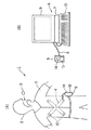
図1ないし図6は本発明の第1の実施の形態に係り、図1は第1の実施の形態を備えたカプセル型内視鏡装置等の構成を示し、図2は第1の実施の形態のカプセル型内視鏡の構成を示し、図3は第2レンズと一体化された透明なカバー部材を示し、図4は撮像部周辺の具体的な構造を示し、図5は変形例における撮像部の構造を示し、図6は変形例における第2レンズと一体化された透明なカバー部材を示す。
【0009】
図1(A)に示すように本発明の第1の実施の形態を備えた内視鏡検査を行うカプセル型内視鏡装置1は、患者2の口部から飲み込まれることにより体腔内管路を通過する際に体腔内管路内壁面を光学的に撮像した画像信号を無線で送信するカプセル型内視鏡3と、このカプセル型内視鏡3で送信された信号を患者2の体外に設けたアンテナユニット4により受け、画像を保存する機能を有する、(患者2の体外に配置される)体外ユニット5とから構成される。
【0010】
この体外ユニット5には、画像データを保存するために、容量が例えば1GBのコンパクトフラッシュ(R)サイズのハードディスクが内蔵されている。
そして、体外ユニット5に蓄積された画像データは検査中或いは検査終了後に図1(B)の表示システム6に接続して、画像を表示することができる。
【0011】
つまり、図1(B)に示すようにこの体外ユニット5は、表示システム6を構成するパーソナルコンピュータ(以下、パソコンと略記)7とUSBケーブル8等の通信を行う通信ケーブルで着脱自在に接続される。
【0012】
そして、パソコン7により体外ユニット5に保存した画像を取り込み、内部のハードディスクに保存したり、表示するため等の処理を行い表示部9により保存した画像を表示できるようにしている。このパソコン7にはデータ入力操作等を行う操作盤としての例えばキーボード10が接続されている。
【0013】
USBケーブル8としては、USB1.0、USB1.1、USB2のいずれの通信規格でも良い。また、この他にRS−232C、IEEE1394の規格のシリラルのデータ通信を行うものでも良いし、シリアルのデータ通信を行うものに限定されるものでなく、パラレルのデータ通信を行うものでも良い。
【0014】
図1(A)に示すようにカプセル型内視鏡3を飲み込んで内視鏡検査を行う場合には、患者2が着るシールド機能を持つシールドシャツ11の内側には複数のアンテナ12が取り付けられたアンテナユニット4が装着され、カプセル型内視鏡3により撮像され、それに内蔵されたアンテナから送信された信号を受け、このアンテナユニット4に接続された体外ユニット5に撮像した画像を保存するようにしている。この体外ユニット5は、例えば患者2のベルトに着脱自在のフックにより取り付けられる。
【0015】
また、この体外ユニット5は例えば箱形状であり、前面には画像表示を行う表示装置としての例えば液晶モニタ13と、制御操作を行う操作ボタン14とが設けてある。また、体外ユニット5の内部には、送受信回路(通信回路)、制御回路、画像データ表示回路、電源を備えている。
【0016】
図2に示すように第1の実施の形態のカプセル型内視鏡3は、円筒形状でその後端を丸くして閉塞した外装ケース16の先端側となる開口する端部に半球面形状の透明カバー17を水密的に接続固定してその内側を密閉し、その密閉したカプセル状容器内に以下の内蔵物を収納している。
【0017】
透明カバー17に対向する中央部には、遮光性のレンズ枠20に固定された対物光学系21が配置され、その結像位置には、基板22の前面に取り付けられたCMOSイメージャ或いはCCD等の撮像センサ23が配置される。
【0018】
この場合、レンズ枠20には対物光学系を構成する第1レンズ24が取り付けられ、第2レンズ25はその後面側に同じ部材で一体成形した透明なカバー部材26が撮像センサ23に取り付けられ、この第2レンズ23の外径に嵌合する内径のレンズ枠20側を光軸O方向に移動してピント出し調整を行い、レンズ枠20側を固定するようにしている。なお、この一体成形する透明な部材としては、ガラス或いは合成樹脂製である。
【0019】
つまり、第2レンズ25は図3(A)及び図3(B)に示すように、前面側は凸となり、その後面側に透明なカバー部材26が一体的に形成されている。なお、図3(A)は側面図を示し、図3(B)は図3(A)の左側から見た正面図を示す。
【0020】
このカバー部材26には撮像センサ(23に取り付けられる)側となる後面は平面部とし、その平面部における四角状の周囲は平面部から同じ高さで突出させた凸面部27が設けてあり、この凸面部27が図4(A)に示すように撮像センサ23の撮像エリア23aの周囲の面に圧着され、封止用の接着剤28で接着固定されている。つまり、撮像センサ23は透明なカバー部材26により、その撮像エリア23aと間隔をあけてカバー部材26で封止するように固定されている。
【0021】
また、レンズ枠20には照明手段としての白色LED31をその前面に取り付けた基板32がその中央に設けた孔部にレンズ枠20を嵌合させて接着剤などで固定されている。
【0022】
この白色LED31には、その発光面に拡散させる機能を持つ拡散板33が取り付けられており、白色LED31のみの場合よりも広範囲の角度で白色の照明光を出射できるようにしている。
また、基板32の背面には、この白色LED31をフラッシュ発光させるLED駆動回路を構成するチップ部品34が実装されている。
【0023】
また、撮像センサをその前面に取り付けた基板22の背面には基板22とで撮像センサ23を駆動すると共に、その出力信号に対する信号処理や、全体の制御を行う駆動&制御回路35、撮像センサ23で撮像した画像情報を無線で送信するための信号処理を行う無線通信回路36、無線通信回路36等に電力を供給するボタン型の2つの電池37がその長手方向に積層するようにして配置されている。
【0024】
また、駆動&制御回路35及び無線通信回路36に隣接する側部には無線通信回路36に接続され、電波で画像情報を送信等するアンテナ38が配置されている。
【0025】
なお、対物光学系21の第1レンズ24の前面には明るさ絞り39(図4(A)参照)が配置され、その入射瞳40の位置は透明カバー17の略半球形状の内面及び外面の曲率半径の中心位置に配置され、その周辺に配置された白色LED31による照明光が内面等で反射された場合にも対物光学系21に入射しないようにしている。なお、図2では対物光学系21による視野角をφで示しており、例えば視野角φは90°〜140°程度である。
【0026】
図4はカプセル状容器内に実際に組み込まれる状態の撮像部周辺(具体的には撮像センサ23周辺及び対物光学系21周辺)の構造を具体的に示したものである。なお、図4(A)は撮像センサ23周辺部の構造を断面を示し、図4(B)は図4(A)のA矢視図を示す。また、図4(A)は図4(B)のB−B′断面を示す。
【0027】
図4(A)に示すように撮像センサ23の撮像面の中央部の撮像(光電変換)を行う撮像エリア23aを覆うように(2次元的に配置された微小レンズアレイからなる)マイクロレンズ41が取り付けられており、このマイクロレンズ41により、(これを設けない場合よりも)撮像エリア23aの各画素に入射される光量を増大してS/Nの良い撮像を行うことができるようにしている。
【0028】
本実施の形態では、このマイクロレンズ41の上面から第2レンズ25と一体成形されたカバー部材26に設けた凸面部27の下面(凸面)で撮像エリア23aの周囲のマイクロレンズ41の上面を圧着し、速効性の接着剤による点付け接着等で短時間にカバー部材26側を固定し、その周囲を接着剤28で封止するように接着している。
【0029】
なお、カバー部材26の凸面部27の高さhは例えば0.05mm〜0.1mm程度であり、この凸面部27によって撮像エリア23aを覆うマイクロレンズ41部分を損傷させないで封止するようにしている。つまり、撮像エリア23a部分は、これに取り付けたマイクロレンズ41から高さh離間して透明なカバー部材26の(凸面部27から引っ込んだ)平面部が平行となるようにして取り付けられる(換言すると、第2レンズ25の光軸が撮像エリア23aの表面に垂直となるようにして取り付けられるようにしている)。
【0030】
また、本実施の形態ではカバー部材26における凸部27の高さを除く厚さdは0.3mm〜0.5mm程度に設定している。また、撮像面と凸部27の下面との間隔φは20ミクロン程度である。さらに第1レンズ25の厚さsは1mm〜1.5mm程度に設定している。
【0031】
そして、本実施の形態では第2レンズ25に嵌合するレンズ枠20を、この第2レンズ25に嵌合させて図4(A)の矢印cで示すように光軸O方向に移動させてピント出し調整を行い、その後に黒色等、遮光性の接着剤42で接着固定するようにしている。
【0032】
このように本実施の形態では、対物光学系21のピント出し調整を行う前に、カバー部材26(に設けた凸面部27)で撮像センサ23の撮像エリア23aの表面と間隔を開けて封止することにより、ピント出し調整の際にゴミが出ても撮像エリア23aに入って付着するようなことを防止すると共に、撮像エリア23aを損傷させるようなことも防止するようにしている。
【0033】
また、図4(A)及び図4(B)に示すように、撮像センサ23のチップは撮像エリア23aの両側の部分でワイヤボンディング43により基板22と電気的に接続されている。
【0034】
なお、図4(A)に示す例では基板22は下側(背面側)の中央部が凹部となる短筒状基板が採用され、その下側の平面には制御用電気部品或いはメモリ部品44が実装されている。そして、ワイヤボンディング45で基板22と電気的に接続され、その周囲は封止樹脂46で封止されている。
【0035】
このような構成の本実施の形態のカプセル型内視鏡3においては、上述したように、カバー部材26(に設けた凸面部27)で撮像センサ23の撮像エリア23aの表面と間隔を開けて封止した後に、対物光学系21のピント出し調整を行う構成になっている。
【0036】
従って、ピント出し調整の際にゴミが出ても撮像エリア23aに入って付着するようなことを防止できると共に、撮像エリア23aを損傷させるようなことも防止できる。
【0037】
従って、本実施の形態は以下の効果を有する。
対物光学系21のピント出し調整を行う前に、カバー部材26(に設けた凸部27)で撮像センサ23の撮像エリア23aの表面と間隔を開けて封止しているので、ピント出し調整の際にゴミが出ても撮像エリア23aに入ってしまうことを防止できると共に、撮像エリア23aを損傷させるようなことも防止でき、良好な画像を得ることができる。
【0038】
また、第2レンズ25はこれと、一体成形したカバー部材26を撮像センサ23の撮像エリア23a周囲の部分に固定する構造にしているので、第2レンズ25を取り付けるレンズ枠を不必要として、他方の第1レンズ24を取り付けた1つのレンズ枠20を第2レンズ25に嵌合移動させてピント出しを行うことができるので、複数のレンズ枠を用いた場合よりもレンズ枠による部品公差によるバラツキを少なくでき、品質の良好な撮像光学系を実現できる。従って、品質の良好な観察画像を得ることができる。
【0039】
図5は変形例による撮像部周辺の構造を示す。本変形例では、レンズ枠20′の内径は第2レンズ25の外径より僅かに大きく形成されており、ピント出し調整を行う場合に、第2レンズ25側に対してレンズ枠20′を図示しない調整治具或いは移動ガイド治具で保持して、図5の光軸O方向に移動する調整の他に、この光軸O方向と直交する2つの方向D、E方向にも調整を行った後、遮光性の接着剤42で固定するようにしている。
【0040】
その他は第1の実施の形態と同様の構成である。本変形例によれば、ピント出し調整を単に光軸O方向の他にこれと直交する2つの方向D,Eに対しても調整を行って固定する、つまり3次元的にピント出し調整を行うので、より精度の良いピント出し状態に設定することができ、より良好な画像を得ることができるようになる。又、第2レンズ25に成形にて使った時の抜き勾配があっても、直接レンズ枠20′を密着させないので問題なく、各部品の精度も厳しくする必要がないので全ての部品を安価な成形品で作れるというメリットがある。
【0041】
図6は変形例のカバー部材26′を示す。
図3では第2レンズ25に一体的に設けたカバー部材26の凸部27の内側は撮像エリア23aより僅かに広い正方形であったが、図6に示す変形例のカバー部材26′のように、撮像エリア23aより僅かに広い円形にしても良い。
【0042】
(第2の実施の形態)
次に本発明の第2の実施の形態を図7及び図8を参照して説明する。図7は第2の実施の形態における撮像部周辺の構造を示し、図8はカバー部材を示す。
第1の実施の形態では、第2レンズ25にカバー部材26を一体的に設けていたが、本実施の形態では第2レンズ25とカバー部材26とを別体にしている。
つまり、撮像センサ23には第1の実施の形態と同様にカバー部材26が撮像エリア23aの周囲のマイクロレンズ41を圧着するようにして取り付けられ、その周囲を接着剤28で封止固定される。
【0043】
そして、このカバー部材26の上面に、第2レンズ25が透明な光学系用接着剤51で位置決めして接合される。その後、第1レンズ24を取り付けたレンズ枠20が第2レンズ25に嵌合し、その光軸O方向に移動してピント出し調整された後、遮光性の接着剤42で固定される。
【0044】
このように本実施の形態では、撮像センサ23の撮像エリア23a部分をカバーする透明カバー部材26を、撮像センサ23の外表面部分のマイクロレンズ41上面に直接、圧着或いは密着して固定し、更に透明カバー部材26の外表面に対物光学系21の第2レンズを密着固定する構成にしていることが特徴となっている。
【0045】
なお、本実施の形態では、凸面部27の高さhは100ミクロン程度、透明なカバー部材26の厚さdは0.4mm〜0.5mm程度に設定され、また撮像面と凸部27の下面との間隔φは20ミクロン程度である。
【0046】
本実施の形態におけるカバー部材26を図8に示す。このカバー部材26は円板形状であり、その周縁は突出する凸面部27が形成されている。この場合、凸面部27の内側の平面部は、例えば円形面となるようにエッチングで形成される。
【0047】
その他の構成は第1の実施の形態と同様である。また、本実施の形態の作用は第1の実施の形態と同様である。
本実施の形態は第1の実施の形態と同様の効果を有すると共に、透明なカバー部材26を金型を用いないで、削り加工で作れるので、材料選択幅を広げることができる。
【0048】
図9は第1変形例における撮像部周辺の構成を示す。第2の実施の形態では、第2レンズ25よりカバー部材26の方がその半径方向のサイズが大きかったが、本変形例では、図9に示すように第2レンズ25の外径D1とカバー部材26の外径D2とを等しくした。
【0049】
そして、レンズ枠20の内径Eに嵌合するサイズにした。つまり、E=D1=D2にした。そして、この図9に示すようにレンズ枠20の嵌合長Lをカバー部材26に嵌合させることができるようになるので、より長くできる。なお、本変形例では基板22は円板形状のものが採用されている。その他は第2の実施の形態と同様の構成である。
【0050】
本変形例によれば、嵌合長Lを長くできるので、第1レンズ24及び第2レンズ25間の光軸O方向からの傾きを減らすことができる。
また接合強度を大きくできる。さらに組立性が向上する。その他は第2の実施の形態と同様の効果がある。
【0051】
図10は第2変形例における撮像部周辺の構成を示す。第1変形例では第2レンズ25の外径D1とカバー部材26の外径D2とを等しくしたが、本変形例では第2レンズ25の外径D1をカバー部材26の外径D2より大きくした。
その他は第1変形例と同様の構成である。
本変形例も第1変形例とほぼ同様の作用効果がある。
【0052】
(第3の実施の形態)
次に本発明の第3の実施の形態を図11及び図12を参照して説明する。図11は第3の実施の形態における対物光学系を取り付ける前の撮像部付近の構成を側面図で示し、図12は上から見た平面図で示す。
本実施の形態では、撮像センサ23は正方形の薄板形状であるが、その撮像エリア23aは図12に示すように円形に形成されている。また、この撮像エリア23を覆うマイクロレンズ41も円形に形成されている。
【0053】
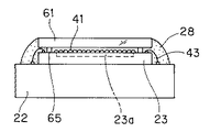
また、本実施の形態では、この撮像面における撮像エリア23a周囲の複数箇所、具体的には撮像センサ23の4隅部分に円板形状で上方に同じ高さで突出する凸面部62が、例えば一体的に設けてある。
【0054】
そして、この凸面部62を設けた撮像センサ23の上面に、例えば正方形の平板形状の透明なカバー部材61がその4隅の凸面部62に、加圧して点付け接着等して、撮像面の前面をカバー部材26が平行となるようにして覆うようにしている。
【0055】
そして、ワイヤボンディング63部分も含めて封止用の接着剤28でその周囲を封止するようにしている。
なお、凸面部62の高さhは例えば50ミクロン程度である。このカバー部材26の上面には例えば、図7に示す対物光学系21を形成する第2レンズ25が接合され、さらにこの第2レンズ25の外径に嵌合し、第1レンズ24を取り付けたレンズ枠20がピント出しして固定される。
本実施の形態によれば、第2の実施の形態と同様の作用効果がある。
【0056】
(第4の実施の形態)
次に本発明の第4の実施の形態を図13及び図14を参照して説明する。図13は第4の実施の形態における対物光学系を取り付ける前の撮像部付近の構成を側面図で示し、図14は上から見た平面図で示す。
【0057】
第3の実施の形態では、撮像センサ23における撮像エリア23a周囲の4隅に凸面部62を設けていたが、図13及び図14に示す本実施の形態では、撮像センサ23における撮像エリア23a周囲の上面にポリイミド等の薄板や両面テープ等のスペーサ部材65を介してカバー部材61を取り付けるようにしている。
【0058】
つまり、撮像センサ23の撮像エリア23aの周囲の上面部分にスペーサ部材65を取り付け、その上面からカバー部材61を取り付け、接着剤28で封止するようにしている。つまり、本実施の形態では、撮像センサ23やカバー部材61と別のスペーサ部材65を介挿して、撮像センサ23にカバー部材61を取り付けるようにしている。
【0059】
その他は第3の実施の形態と同様の構成である。また、本実施の形態の作用効果は第3の実施の形態とほぼ同様である。
【0060】
(第5の実施の形態)
次に本発明の第5の実施の形態を図15を参照して説明する。図15は第5の実施の形態における撮像部付近の構成を断面図で示す。
本実施の形態では、(対物光学系21を構成する)第2レンズ25には透明なカバー部材71が一体的に設けてあり、このカバー部材71は第2レンズ25の外径より外側に平板状に延出した延出部72が形成されており、この延出部72を短筒状の基板73の上面に当接させて点着け接着し、その後、その接続部周囲を封止用の接着剤28で接着してその内部を封止している。
【0061】
また、短筒状の基板73の内側は2段の段差で中央の平面部が形成され、この平面部には撮像センサ23が取り付けられ、その撮像エリア23aを覆うにマイクロレンズ41が設けてある。そして、そのマイクロレンズ41の両側の部分でワイヤボンディング43により基板73の回路と電気的に接続されている。
【0062】
本実施の形態では、カバー部材71は、第2レンズ25に対向する部分が厚肉にされ、その下面がマイクロレンズ41と僅かに離間するようにして、カバー部材71の周辺の延出部72を基板73に、この延出部72の平面が撮像エリア23aの面と平行となるようにして固定している。
【0063】
なお、第2レンズ25には、例えば第1の実施の形態のようにして、第1レンズを取り付けたレンズ枠20がピント出し調整して取り付けられる。
本実施の形態によれば、第1の実施の形態と同様に部品点数を削減でき、製造コストを削減できる。また、バラツキ低減化することもできる。
【0064】
(第6の実施の形態)
次に本発明の第6の実施の形態を図16を参照して説明する。図16は第6の実施の形態における撮像部付近の構成を断面図で示す。
第5の実施の形態では、カバー部材71は板状の延出部72を設けてその周縁部を基板73に固定していたが、本実施の形態では、カバー部材71には図15の延出部72の端部からさらに筒状にした筒部75が形成され、この筒部75の端面を基板76に点付け接着し、延出部72の平面が撮像エリア23aの面と平行となるように固定し、その後接着剤28で接着してその内部を封止するようにしている。
【0065】
また、本実施の形態では基板76はその上面側は平面形状で、その中央部に撮像センサ23が取り付けられ、中央の撮像エリア23aの両側でワイヤボンディング43により基板76と電気的に接続されている。
【0066】
また、この基板76の裏面側は第1の実施の形態と同様に短筒状にされ、電気部品やメモリ部品44が実装され、ワイヤボンディング45で基板76と接続され、その周囲は封止樹脂46で封止されている。
【0067】
本実施の形態は第5の実施の形態とほぼ同様の作用効果を有する。
なお、上述した各実施の形態等を部分的等で組み合わせて構成される実施の形態等も本発明に属する。
【0068】
[付記]
4.請求項1において、前記撮像センサの周辺には白色LEDが配置され、さらに前記撮像センサの前面には、白色LEDの色補正フィルタが装着されていることを特徴とする。
5.請求項1において、前記撮像センサは、MOS型イメージセンサである。
6.前記撮像センサは、CCD型イメージセンサである。
7.請求項1において、前記撮像エリア表面に対向する透明カバー部材表面が略平行となるように、撮像センサ表面の撮像エリア以外の部分に凸部を設けた。
【0069】
7−1.付記7において、前記凸部は撮像センサに一体的に形成される。
7−2.付記7において、前記凸部は撮像センサと別体の部材によって形成される。
【0070】
8.請求項1において、前記撮像エリア表面に対向する透明カバー部材表面が略平行となるように、透明カバー部材は撮像センサが取り付けられた基板に固定される。
9.請求項1において、透明カバー部材の周辺部に凸部を設け、該凸部は複数箇所で撮像センサ表面に固定され、撮像エリア表面と対向する透明カバー部材表面が略平行となるように設けた。
10.請求項1において、前記透明カバー部材の外面に直接、対物光学系の第2レンズを密着固定する構成にした。
【0071】
11.請求項1において、前記透明カバー部材の外径と対物光学系の第2レンズの外径は略同一径もしくは、第2の対物レンズ外面の方が若干大きくなるように設定している。
12.請求項1において、前記透明カバー部材の撮像センサ側は平坦面で外面側は凸レンズ状に構成し、上記透明カバー部材と対物光学系の第2レンズを一つの部材で兼用する構成とした。
13.付記12において、透明カバー部材と凸レンズは合成樹脂またはガラス製の一体成形品である。
14.請求項1において、前記対物光学系の入射瞳の位置は前記透明カバー部材における半球状の曲率半径の中心位置に配置される。
【0072】
15.撮像センサと、該撮像センサ前方の対物光学系と、を密閉カプセルに内蔵するカプセル型内視鏡において、
少なくとも該撮像センサの撮像エリア部分をカバーする透明カバー部材を、該撮像センサ外表面を覆うように固定し、更に透明カバー部材の外表面に対物光学系を構成する第2レンズを密着固定したことを特徴とするカプセル型内視鏡。
【0073】
16.付記15において、前記撮像センサが撮像し、出力した画像信号を体外に送信する送信手段を有する。
17.付記15において、前記透明カバー部材の外面と対物光学系の第2レンズの外経は略同一径もしくは、第2レンズ外経の方が若干大きくなるように設定してある。
【0074】
18.付記15において、前記透明カバー部材の撮像センサ側は平坦面で外面側は凸レンズ状に構成し、上記透明カバー部材と第2レンズを一つの部材で兼用する構成とした。
19.付記15において、前記対物光学系を構成する第1レンズを取り付けたレンズ枠の内径は、第2レンズ外径より大きく、移動ガイドを使って第2レンズに対して第1レンズ側を前後に移動してピント出し調整を行う際に、3次元的な位置合わせを行って固定する構成とした。
【0075】
20.付記15において、前記対物光学系の第1レンズは遮光枠に固定してあり、遮光枠内面と第2レンズの外径を略嵌合して両者を相対的に移動させることで、対物光学系のピント出し調整を行う構成とした。
21.付記15において、前記対物光学系は第1レンズと第2レンズとで構成され、両レンズは共に凸レンズで構成される。
22.付記15において、対物光学系を構成する第1レンズが取り付けられた遮光枠の周囲に生体内を照明する照明手段を固定し、照明手段と対物光学系の前方を透明カバーで覆うようにした。
【0076】
23.撮像センサと、該撮像センサ前方の対物光学系と、を密閉カプセルに内蔵するカプセル型内視鏡において、
少なくとも該撮像センサの撮像エリア部分をカバーする透明カバー部材を、該撮像センサ外表面を覆うように固定し、更に透明カバー部材の外表面に対物光学系を構成する第2レンズを一体又は別体で固定し、この第2レンズの外径に嵌合する第1レンズを取り付けた単一のレンズ枠を光軸方向に相対的に移動してピント出しして固定するようにしたことを特徴とするカプセル型内視鏡。
【0077】
(付記15〜23の背景)
従来技術として特開2001−91860号公報がある。
(従来技術の概要と不具合)
略半球状の透明カバー内に対物レンズと照明体を固定したものであり、剥き出しのイメージセンサを固定した回路基盤を収納した電気要素保持筒に対して、対物レンズ鏡筒を移動させてピント出しを行った後、固定ネジで対物レンズ鏡筒をレンズ保持筒に固定するものであった。
このため、ピント出し時に生じるレンズ枠の削れカス等のごみが剥き出しの撮像(イメージ)センサの前面に付着し、ごみによって良好画像が得られなくなる可能性が高いと共に、イメージセンサと対物レンズとは複数の部材を介して位置出しを行う構成のために、多くの部品公差の積算によるバラツキにより画角や被写界深度等の光学性能が固体毎に大きくバラツクという不具合があった。
【0078】
(目的)
複数の枠部材を使わずにピント出しでき、しかもピント出し時のごみの影響を少なくでき、且つレンズ枠部材の部品公差によるバラツキを少なくできるカプセル型内視鏡を提供することを目的とする。そして、この目的を達成するために、付記15〜23の構成にした。
【0079】
【発明の効果】
以上説明したように本発明によれば、対物光学系のピント出し調整を行う前に、透明カバー部材に設けた凸面部によって撮像センサの撮像エリアの表面と間隔を開けて封止することにより、ピント出し調整の際にゴミが出ても撮像エリアに入って付着することを防止でき、また撮像エリアの損傷を防止できる。
【図面の簡単な説明】
【図1】本発明の第1の実施の形態を備えたカプセル型内視鏡装置等の構成を示す図。
【図2】第1の実施の形態のカプセル型内視鏡の構成を示す断面図。
【図3】第2レンズと一体化された透明なカバー部材を示す図。
【図4】撮像部周辺の具体的な構造を示す図。
【図5】変形例における撮像部周辺の構造を示す断面図。
【図6】変形例における第2レンズと一体化された透明なカバー部材を示す図。
【図7】本発明の第2の実施の形態における撮像部周辺の構造を示す断面図。
【図8】カバー部材を示す図。
【図9】第1変形例における撮像部周辺の構造を示す断面図。
【図10】第2変形例における撮像部周辺の構造を示す断面図。
【図11】本発明の第3の実施の形態における対物光学系を取り付ける前の撮像部の構造を示す側面図。
【図12】図11の上から見た平面図。
【図13】本発明の第4の実施の形態における撮像部の構造を示す図。
【図14】図13の上から見た平面図。
【図15】本発明の第5の実施の形態における撮像部の構造を示す図。
【図16】本発明の第6の実施の形態における撮像部の構造を示す図。
【符号の説明】
1…カプセル型内視鏡装置
2…患者
3…カプセル型内視鏡
4…アンテナユニット
5…体外ユニット
6…表示システム
7…パソコン
8…USBケーブル
11…シールドシャツ
12…アンテナ
13…液晶モニタ
16…外装ケース
17…透明カバー
20…レンズ枠
21…対物光学系
22、32…基板
23…CMOSイメージャ
23a…撮像エリア
24…第1レンズ
25…第2レンズ
26…カバー部材
27…凸面部
28、42…接着剤
31…白色LED
35…駆動&制御回路
36…無線通信回路
37…電池
38…アンテナ
40…入射瞳
41…マイクロレンズ
43…ワイヤボンディング[0001]
BACKGROUND OF THE INVENTION
The present invention relates to a swallowable capsule endoscope that inspects a living body.
[0002]
[Prior art]
In recent years, endoscopes have been widely adopted in the medical field and the industrial field. In recent years, the medical field has been able to reduce the pain of insertion due to insertion by a patient swallowing a capsule-type capsule endoscope without the need for an insertion part in an endoscope. The situation is now in use.
For example, there exists Unexamined-Japanese-Patent No. 2001-91860.
[0003]
In this conventional example, the objective lens and the illumination means by the light emitting element provided symmetrically so as to sandwich the objective lens are incorporated inside the substantially hemispherical transparent cover, and the object illuminated by the light emitting element is a portion that is an observation range Is imaged on the image sensor by the objective optical system.
[0004]
In this conventional example, the objective lens is fixed in the transparent cover. After the object lens barrel is moved and focused with respect to the exposed image sensor, the lens holding cylinder is fixed with a fixing screw. It is considered to be a fixed structure.
[0005]
[Problems to be solved by the invention]
For this reason, in the above conventional example, dust such as scraped lens frames generated at the time of focusing adheres to the front surface of the imaging sensor, and it is difficult to obtain a good image or damage the imaging area. There was a problem that it was expensive.
[0006]
(Object of invention)
The present invention has been made in view of the above points.Before adjusting the focus of the objective optical system, by sealing the surface of the imaging area of the imaging sensor with a convex portion provided on the transparent cover member,Focus adjustmentAt the time ofEven if garbage comes outPrevents sticking into the imaging area and prevents damage to the imaging areaAn object of the present invention is to provide a capsule endoscope.
[0007]
[Means for Solving the Problems]
A capsule endoscope according to an aspect of the present invention is a capsule endoscope in which an imaging sensor and an objective optical system in front of the imaging sensor are incorporated in a sealed capsule.
A transparent cover member that covers at least the imaging area portion of the imaging sensor is fixed so as to cover the outer surface of the imaging sensor, and a second lens that constitutes the objective optical system is closely fixed to the outer surface of the transparent cover member. The inner diameter of the lens frame to which the first lens constituting the objective optical system is attached is larger than the outer diameter of the second lens, and the first lens side is moved back and forth with respect to the second lens using a moving guide. When the adjustment is performed, three-dimensional alignment is performed and fixed.
[0008]
DETAILED DESCRIPTION OF THE INVENTION
Embodiments of the present invention will be described below with reference to the drawings.
(First embodiment)
1 to 6 relate to a first embodiment of the present invention, FIG. 1 shows a configuration of a capsule endoscope apparatus or the like provided with the first embodiment, and FIG. 2 shows a first embodiment. FIG. 3 shows a transparent cover member integrated with the second lens, FIG. 4 shows a specific structure around the imaging unit, and FIG. FIG. 6 shows a transparent cover member integrated with the second lens in the modification.
[0009]
As shown in FIG. 1 (A), a
[0010]
The extracorporeal unit 5 has a built-in compact flash (R) hard disk having a capacity of, for example, 1 GB in order to store image data.
The image data stored in the extracorporeal unit 5 can be connected to the
[0011]
That is, as shown in FIG. 1B, the extracorporeal unit 5 is detachably connected to a personal computer (hereinafter abbreviated as a personal computer) 7 constituting the
[0012]
Then, the image stored in the external unit 5 is captured by the
[0013]
The
[0014]
As shown in FIG. 1A, when performing an endoscopic examination by swallowing the capsule endoscope 3, a plurality of
[0015]
The extracorporeal unit 5 has, for example, a box shape, and is provided with, for example, a
[0016]
As shown in FIG. 2, the capsule endoscope 3 according to the first embodiment has a cylindrical shape and a hemispherical transparent shape at the open end which is the front end side of the
[0017]
An objective
[0018]
In this case, the
[0019]
That is, as shown in FIGS. 3A and 3B, the
[0020]
This
[0021]
Further, a
[0022]
The
On the back surface of the
[0023]
In addition, the
[0024]
In addition, an
[0025]
Note that an aperture stop 39 (see FIG. 4A) is disposed on the front surface of the
[0026]
FIG. 4 specifically shows the structure around the imaging unit (specifically, around the
[0027]
As shown in FIG. 4A, a microlens 41 (comprising a microlens array arranged two-dimensionally) so as to cover an
[0028]
In the present embodiment, the upper surface of the
[0029]
The height h of the
[0030]
In the present embodiment, the thickness d excluding the height of the
[0031]
In this embodiment, the
[0032]
As described above, in this embodiment, before the focus adjustment of the objective
[0033]
Also, as shown in FIGS. 4A and 4B, the chip of the
[0034]
In the example shown in FIG. 4A, the
[0035]
In the capsule endoscope 3 of the present embodiment having such a configuration, as described above, the cover member 26 (
[0036]
Therefore, even if dust comes out during focus adjustment, it can be prevented from entering and adhering to the
[0037]
Therefore, this embodiment has the following effects.
Before the focus adjustment of the objective
[0038]
Further, since the
[0039]
FIG. 5 shows a structure around the imaging unit according to a modification. In this modification, the inner diameter of the
[0040]
The other configuration is the same as that of the first embodiment. According to this modification, the focus adjustment is not only performed in the direction of the optical axis O but also fixed in two directions D and E perpendicular to the optical axis O, that is, three-dimensional focus adjustment is performed. Therefore, it is possible to set a more accurate focus state, and it is possible to obtain a better image. Even if the
[0041]
FIG. 6 shows a cover member 26 'according to a modification.
In FIG. 3, the inside of the
[0042]
(Second Embodiment)
Next, a second embodiment of the present invention will be described with reference to FIGS. FIG. 7 shows a structure around the imaging unit in the second embodiment, and FIG. 8 shows a cover member.
In the first embodiment, the
That is, as in the first embodiment, the
[0043]
The
[0044]
As described above, in the present embodiment, the
[0045]
In the present embodiment, the height h of the
[0046]
The
[0047]
Other configurations are the same as those of the first embodiment. The operation of the present embodiment is the same as that of the first embodiment.
The present embodiment has the same effects as the first embodiment, and the
[0048]
FIG. 9 shows a configuration around the imaging unit in the first modification. In the second embodiment, the radial size of the
[0049]
And it was set as the size fitted to the inner diameter E of the
[0050]
According to this modification, since the fitting length L can be increased, the inclination from the optical axis O direction between the
Also, the bonding strength can be increased. Furthermore, the assemblability is improved. Other effects are the same as those of the second embodiment.
[0051]
FIG. 10 shows a configuration around the imaging unit in the second modification. In the first modification, the outer diameter D1 of the
Other configurations are the same as those of the first modification.
This modification also has substantially the same function and effect as the first modification.
[0052]
(Third embodiment)
Next, a third embodiment of the present invention will be described with reference to FIGS. FIG. 11 is a side view showing the configuration in the vicinity of the imaging unit before the objective optical system is attached in the third embodiment, and FIG. 12 is a plan view seen from above.
In the present embodiment, the
[0053]
Further, in the present embodiment, the
[0054]
Then, on the upper surface of the
[0055]
Then, the periphery including the wire bonding 63 portion is sealed with a sealing
The height h of the
According to the present embodiment, there are the same functions and effects as those of the second embodiment.
[0056]
(Fourth embodiment)
Next, a fourth embodiment of the present invention will be described with reference to FIGS. FIG. 13 is a side view showing the configuration in the vicinity of the imaging unit before attaching the objective optical system in the fourth embodiment, and FIG. 14 is a plan view seen from above.
[0057]
In the third embodiment, the
[0058]
That is, the
[0059]
The other configuration is the same as that of the third embodiment. The operational effects of the present embodiment are almost the same as those of the third embodiment.
[0060]
(Fifth embodiment)
Next, a fifth embodiment of the present invention will be described with reference to FIG. FIG. 15 is a cross-sectional view showing the configuration in the vicinity of the imaging unit in the fifth embodiment.
In the present embodiment, a
[0061]
Further, the inner side of the short
[0062]
In the present embodiment, the
[0063]
For example, as in the first embodiment, the
According to the present embodiment, the number of parts can be reduced as in the first embodiment, and the manufacturing cost can be reduced. In addition, variation can be reduced.
[0064]
(Sixth embodiment)
Next, a sixth embodiment of the present invention will be described with reference to FIG. FIG. 16 is a cross-sectional view showing the configuration in the vicinity of the imaging unit in the sixth embodiment.
In the fifth embodiment, the
[0065]
Further, in the present embodiment, the
[0066]
Further, the back surface side of the
[0067]
The present embodiment has substantially the same function and effect as the fifth embodiment.
Note that embodiments and the like configured by partially combining the above-described embodiments and the like also belong to the present invention.
[0068]
[Appendix]
4). In
5. 2. The imaging sensor according to
6). The imaging sensor is a CCD image sensor.
7. In
[0069]
7-1. In
7-2. In
[0070]
8). In
9. In
10. In
[0071]
11. In
12 According to a first aspect of the present invention, the imaging sensor side of the transparent cover member is a flat surface and the outer surface side is formed in a convex lens shape, and the transparent cover member and the second lens of the objective optical system are used as a single member.
13. In
14 In
[0072]
15. In a capsule endoscope in which an imaging sensor and an objective optical system in front of the imaging sensor are incorporated in a sealed capsule,
A transparent cover member that covers at least the imaging area of the imaging sensor is fixed so as to cover the outer surface of the imaging sensor, and a second lens constituting the objective optical system is closely fixed to the outer surface of the transparent cover member. Capsule endoscope characterized by this.
[0073]
16. In Supplementary Note 15, the image sensor includes a transmission unit that captures an image and transmits the output image signal outside the body.
17. In Supplementary Note 15, the outer diameter of the transparent cover member and the outer diameter of the second lens of the objective optical system are set to be substantially the same diameter, or the second lens outer diameter is slightly larger.
[0074]
18. In Supplementary Note 15, the imaging sensor side of the transparent cover member is configured as a flat surface and the outer surface side is configured as a convex lens, and the transparent cover member and the second lens are combined into one member.
19. In Additional Statement 15, the inner diameter of the lens frame to which the first lens constituting the objective optical system is attached is larger than the outer diameter of the second lens, and the first lens side is moved back and forth with respect to the second lens using a moving guide. Thus, when the focus adjustment is performed, a three-dimensional alignment is performed and fixed.
[0075]
20. In Supplementary Note 15, the first lens of the objective optical system is fixed to the light shielding frame, and the objective optical system is moved by relatively fitting the inner surface of the light shielding frame and the outer diameter of the second lens to relatively move both. The focus adjustment is adjusted.
21. In Supplementary Note 15, the objective optical system includes a first lens and a second lens, and both the lenses include a convex lens.
22. In Supplementary Note 15, the illuminating means for illuminating the inside of the living body is fixed around the light shielding frame to which the first lens constituting the objective optical system is attached, and the front of the illuminating means and the objective optical system is covered with a transparent cover.
[0076]
23. In a capsule endoscope in which an imaging sensor and an objective optical system in front of the imaging sensor are incorporated in a sealed capsule,
A transparent cover member that covers at least the imaging area portion of the imaging sensor is fixed so as to cover the outer surface of the imaging sensor, and a second lens constituting the objective optical system is integrated or separated on the outer surface of the transparent cover member. A single lens frame attached with the first lens fitted to the outer diameter of the second lens is moved relative to the optical axis direction to focus out and be fixed. Capsule type endoscope.
[0077]
(Background to Appendix 15-23)
There exists Unexamined-Japanese-Patent No. 2001-91860 as a prior art.
(Overview of conventional technology and problems)
The objective lens and illuminator are fixed in a substantially hemispherical transparent cover, and the objective lens barrel is moved out of focus with respect to the electric element holding cylinder containing the circuit board on which the exposed image sensor is fixed. Then, the objective lens barrel was fixed to the lens holding cylinder with a fixing screw.
For this reason, dust such as scraped debris from the lens frame that is generated when focusing is adhered to the front surface of the exposed imaging (image) sensor, and there is a high possibility that a good image will not be obtained due to dust, and the image sensor and objective lens Due to the configuration in which positioning is performed via a plurality of members, there has been a problem that optical performance such as angle of field and depth of field greatly varies from one solid to another due to variations due to the integration of many component tolerances.
[0078]
(the purpose)
It is an object of the present invention to provide a capsule endoscope that can be focused without using a plurality of frame members, can reduce the influence of dust at the time of focusing, and can reduce variations due to component tolerances of the lens frame members. And in order to achieve this objective, it was set as the structure of additional remarks 15-23.
[0079]
【The invention's effect】
As described above, according to the present invention,Before adjusting the focus of the objective optical system, the convex surface provided on the transparent cover member is sealed with a gap from the surface of the imaging area of the imaging sensor so that dust can be removed during focus adjustment. It is possible to prevent adhering to the imaging area and to prevent the imaging area from being damaged.
[Brief description of the drawings]
FIG. 1 is a diagram showing a configuration of a capsule endoscope apparatus or the like provided with a first embodiment of the present invention.
FIG. 2 is a cross-sectional view showing the configuration of the capsule endoscope according to the first embodiment.
FIG. 3 is a view showing a transparent cover member integrated with a second lens.
FIG. 4 is a diagram showing a specific structure around an imaging unit.
FIG. 5 is a cross-sectional view showing a structure around an imaging unit in a modified example.
FIG. 6 is a view showing a transparent cover member integrated with a second lens in a modified example.
FIG. 7 is a cross-sectional view showing a structure around an imaging unit according to a second embodiment of the present invention.
FIG. 8 is a view showing a cover member.
FIG. 9 is a cross-sectional view showing a structure around an imaging unit in a first modification.
FIG. 10 is a cross-sectional view showing a structure around an imaging unit in a second modification.
FIG. 11 is a side view showing a structure of an imaging unit before an objective optical system is attached in the third embodiment of the present invention.
12 is a plan view seen from above in FIG.
FIG. 13 is a diagram illustrating a structure of an imaging unit according to a fourth embodiment of the present invention.
14 is a plan view seen from above in FIG. 13;
FIG. 15 is a diagram showing a structure of an imaging unit in a fifth embodiment of the present invention.
FIG. 16 is a diagram illustrating a structure of an imaging unit according to a sixth embodiment of the present invention.
[Explanation of symbols]
1 ... Capsule endoscope device
2 ... Patient
3 ... Capsule endoscope
4 ... Antenna unit
5 ... Extracorporeal unit
6 ... Display system
7 ... PC
8 ... USB cable
11 ... Shield shirt
12 ... Antenna
13 ... LCD monitor
16 ... exterior case
17 ... Transparent cover
20 ... Lens frame
21 ... Objective optical system
22, 32 ... substrate
23 ... CMOS imager
23a ... Imaging area
24 ... 1st lens
25. Second lens
26: Cover member
27 ... Convex part
28, 42 ... Adhesive
31 ... White LED
35 ... Drive & control circuit
36. Wireless communication circuit
37 ... Battery
38 ... Antenna
40 ... Entrance pupil
41 ... Microlens
43 ... Wire bonding
Claims (1)
少なくとも前記撮像センサの撮像エリア部分をカバーする透明カバー部材を、前記撮像センサ外表面を覆うように固定し、更に前記透明カバー部材の外表面に対物光学系を構成する第2レンズを密着固定し、前記対物光学系を構成する第1レンズを取り付けたレンズ枠の内径を第2レンズ外径より大きくて、移動ガイドを使って第2レンズに対して第1レンズ側を前後に移動してピント出し調整を行う際に、3次元的な位置合わせを行って固定することを特徴とするカプセル型内視鏡。In a capsule endoscope in which an imaging sensor and an objective optical system in front of the imaging sensor are incorporated in a sealed capsule,
A transparent cover member that covers at least the imaging area portion of the imaging sensor is fixed so as to cover the outer surface of the imaging sensor, and a second lens that constitutes the objective optical system is closely fixed to the outer surface of the transparent cover member. The inner diameter of the lens frame to which the first lens constituting the objective optical system is attached is larger than the outer diameter of the second lens, and the first lens side is moved back and forth with respect to the second lens using a moving guide. A capsule endoscope characterized by performing three-dimensional alignment and fixing when performing adjustment.
Priority Applications (2)
| Application Number | Priority Date | Filing Date | Title |
|---|---|---|---|
| JP2002064017A JP4009473B2 (en) | 2002-03-08 | 2002-03-08 | Capsule endoscope |
| US10/352,110 US7022066B2 (en) | 2002-03-08 | 2003-01-28 | Capsule endoscope |
Applications Claiming Priority (1)
| Application Number | Priority Date | Filing Date | Title |
|---|---|---|---|
| JP2002064017A JP4009473B2 (en) | 2002-03-08 | 2002-03-08 | Capsule endoscope |
Publications (3)
| Publication Number | Publication Date |
|---|---|
| JP2003260023A JP2003260023A (en) | 2003-09-16 |
| JP2003260023A5 JP2003260023A5 (en) | 2005-09-02 |
| JP4009473B2 true JP4009473B2 (en) | 2007-11-14 |
Family
ID=28670973
Family Applications (1)
| Application Number | Title | Priority Date | Filing Date |
|---|---|---|---|
| JP2002064017A Expired - Fee Related JP4009473B2 (en) | 2002-03-08 | 2002-03-08 | Capsule endoscope |
Country Status (2)
| Country | Link |
|---|---|
| US (1) | US7022066B2 (en) |
| JP (1) | JP4009473B2 (en) |
Families Citing this family (97)
| Publication number | Priority date | Publication date | Assignee | Title |
|---|---|---|---|---|
| IL130486A (en) * | 1999-06-15 | 2005-08-31 | Given Imaging Ltd | Optical system |
| US7996067B2 (en) * | 1999-06-15 | 2011-08-09 | Given Imaging Ltd. | In-vivo imaging device, optical system and method |
| US7813789B2 (en) * | 1999-06-15 | 2010-10-12 | Given Imaging Ltd. | In-vivo imaging device, optical system and method |
| IL143259A (en) | 2001-05-20 | 2006-08-01 | Given Imaging Ltd | Method for moving an object through the colon |
| US7727169B1 (en) | 2001-06-11 | 2010-06-01 | Given Imaging, Ltd. | Device for in vivo sensing |
| US7998065B2 (en) | 2001-06-18 | 2011-08-16 | Given Imaging Ltd. | In vivo sensing device with a circuit board having rigid sections and flexible sections |
| US8428685B2 (en) * | 2001-09-05 | 2013-04-23 | Given Imaging Ltd. | System and method for magnetically maneuvering an in vivo device |
| WO2003021529A2 (en) * | 2001-09-05 | 2003-03-13 | Given Imaging Ltd. | System and method for three dimensional display of body lumens |
| IL153510A0 (en) * | 2001-12-18 | 2003-07-06 | Given Imaging Ltd | Device, system and method for capturing in-vivo images with three-dimensional aspects |
| US6958034B2 (en) * | 2002-02-11 | 2005-10-25 | Given Imaging Ltd. | Self propelled device |
| US6939290B2 (en) * | 2002-02-11 | 2005-09-06 | Given Imaging Ltd | Self propelled device having a magnetohydrodynamic propulsion system |
| JP4363843B2 (en) | 2002-03-08 | 2009-11-11 | オリンパス株式会社 | Capsule endoscope |
| US7662094B2 (en) | 2002-05-14 | 2010-02-16 | Given Imaging Ltd. | Optical head assembly with dome, and device for use thereof |
| AU2003224415A1 (en) | 2002-05-16 | 2003-12-02 | Cbyond Inc. | Miniature camera head |
| US7473218B2 (en) * | 2002-08-06 | 2009-01-06 | Olympus Corporation | Assembling method of capsule medical apparatus |
| WO2004014227A1 (en) * | 2002-08-13 | 2004-02-19 | Given Imaging Ltd. | System for in vivo sampling and analysis |
| US8449452B2 (en) * | 2002-09-30 | 2013-05-28 | Given Imaging Ltd. | In-vivo sensing system |
| US7662093B2 (en) * | 2002-09-30 | 2010-02-16 | Given Imaging, Ltd. | Reduced size imaging device |
| JP4746876B2 (en) | 2002-10-15 | 2011-08-10 | ギブン イメージング リミテッド | Apparatus, system and method for transferring a signal to a mobile device |
| JP4634707B2 (en) * | 2002-10-30 | 2011-02-16 | ギブン イメージング リミテッド | In-vivo device, in-vivo sensing device, in-vivo device operating method, and autonomous in-vivo sensing device operating method |
| US20080045788A1 (en) * | 2002-11-27 | 2008-02-21 | Zvika Gilad | Method and device of imaging with an in vivo imager |
| US7637865B2 (en) * | 2002-12-26 | 2009-12-29 | Given Imaging, Ltd. | In vivo imaging device |
| WO2004058041A2 (en) | 2002-12-26 | 2004-07-15 | Given Imaging Ltd. | Immobilizable in vivo sensing device |
| JP4550048B2 (en) * | 2003-05-01 | 2010-09-22 | ギブン イメージング リミテッド | Panorama field of view imaging device |
| KR100539234B1 (en) * | 2003-06-11 | 2005-12-27 | 삼성전자주식회사 | A CMOS type image sensor module having transparent polymeric encapsulation material |
| EP1641390A4 (en) * | 2003-06-26 | 2008-06-04 | Given Imaging Ltd | Methods, device and system for in vivo detection |
| EP2316328B1 (en) | 2003-09-15 | 2012-05-09 | Super Dimension Ltd. | Wrap-around holding device for use with bronchoscopes |
| DE602004022432D1 (en) | 2003-09-15 | 2009-09-17 | Super Dimension Ltd | SYSTEM FROM ACCESSORIES FOR USE WITH BRONCHOSCOPES |
| JP3958735B2 (en) * | 2003-10-24 | 2007-08-15 | オリンパス株式会社 | Intra-subject introduction device |
| US8639314B2 (en) * | 2003-12-24 | 2014-01-28 | Given Imaging Ltd. | Device, system and method for in-vivo imaging of a body lumen |
| US7821564B2 (en) * | 2003-12-30 | 2010-10-26 | Given Imaging Ltd. | Assembly for aligning an optical system |
| WO2005062717A2 (en) | 2003-12-31 | 2005-07-14 | Given Imaging Ltd. | In-vivo sensing device with detachable part |
| EP1707102B1 (en) | 2004-01-19 | 2010-05-05 | Olympus Corporation | Capsule type medical treatment device |
| WO2005067783A1 (en) * | 2004-01-19 | 2005-07-28 | Olympus Corporation | Imaging device for endoscope and capsule type endoscope |
| JP2005205077A (en) * | 2004-01-26 | 2005-08-04 | Olympus Corp | Capsule type endoscope |
| US8764725B2 (en) | 2004-02-09 | 2014-07-01 | Covidien Lp | Directional anchoring mechanism, method and applications thereof |
| US20050195785A1 (en) * | 2004-03-08 | 2005-09-08 | Pentax Corporation | Image signal processing device |
| JP2005245937A (en) * | 2004-03-08 | 2005-09-15 | Pentax Corp | Clothing with communication function and endoscope system |
| US8500630B2 (en) * | 2004-06-30 | 2013-08-06 | Given Imaging Ltd. | In vivo device with flexible circuit board and method for assembly thereof |
| WO2006003650A2 (en) * | 2004-06-30 | 2006-01-12 | Given Imaging Ltd. | In-vivo sensing system device and method for real time viewing |
| US7336833B2 (en) * | 2004-06-30 | 2008-02-26 | Given Imaging, Ltd. | Device, system, and method for reducing image data captured in-vivo |
| US20060015013A1 (en) * | 2004-06-30 | 2006-01-19 | Zvika Gilad | Device and method for in vivo illumination |
| US7596403B2 (en) | 2004-06-30 | 2009-09-29 | Given Imaging Ltd. | System and method for determining path lengths through a body lumen |
| TWM267483U (en) * | 2004-07-16 | 2005-06-11 | Kingpak Tech Inc | Image sensor module |
| US7057833B2 (en) * | 2004-09-03 | 2006-06-06 | Yeow-Thiam Ooi | Image capture device |
| IL171772A (en) * | 2004-11-04 | 2009-11-18 | Given Imaging Ltd | Apparatus and method for receiving device selection and combining |
| JP2006149461A (en) * | 2004-11-25 | 2006-06-15 | Olympus Corp | Device for acquiring information inside subject |
| JP2006149462A (en) * | 2004-11-25 | 2006-06-15 | Olympus Corp | Device for acquiring information inside subject |
| US20060164510A1 (en) * | 2005-01-24 | 2006-07-27 | Doron Adler | Sensor with narrow mounting profile |
| AU2006209044A1 (en) * | 2005-01-27 | 2006-08-03 | Super Dimension Ltd. | Endoscope with miniature imaging arrangement |
| US20060217593A1 (en) * | 2005-03-24 | 2006-09-28 | Zvika Gilad | Device, system and method of panoramic multiple field of view imaging |
| IL167782A (en) * | 2005-03-31 | 2011-12-29 | Given Imaging Ltd | Antenna for in-vivo imaging system |
| IL174531A0 (en) * | 2005-04-06 | 2006-08-20 | Given Imaging Ltd | System and method for performing capsule endoscopy diagnosis in remote sites |
| JP2007007227A (en) * | 2005-07-01 | 2007-01-18 | Pentax Corp | Image pick up device for electronic endoscope |
| JP4864364B2 (en) * | 2005-07-11 | 2012-02-01 | Hoya株式会社 | Imaging unit for electronic endoscope |
| US9320417B2 (en) | 2005-12-29 | 2016-04-26 | Given Imaging Ltd. | In-vivo optical imaging device with backscatter blocking |
| US20070167834A1 (en) * | 2005-12-29 | 2007-07-19 | Amit Pascal | In-vivo imaging optical device and method |
| US20070156051A1 (en) * | 2005-12-29 | 2007-07-05 | Amit Pascal | Device and method for in-vivo illumination |
| KR100741619B1 (en) * | 2006-01-03 | 2007-07-23 | 킹팍 테크놀로지 인코포레이티드 | Method for manufacturing an image sensor module structure |
| US9084547B2 (en) * | 2006-03-30 | 2015-07-21 | Given Imaging Ltd. | System and method for checking the status of an in-vivo imaging device |
| CN101404922B (en) * | 2006-04-25 | 2011-02-02 | 奥林巴斯医疗株式会社 | Encapsulated endoscope |
| JP4308233B2 (en) | 2006-09-01 | 2009-08-05 | オリンパスメディカルシステムズ株式会社 | Imaging module for endoscope |
| WO2008026199A1 (en) * | 2006-09-01 | 2008-03-06 | Stryker Gi Ltd. | Pcb board for hybrid circuit of an image sensor |
| US8512241B2 (en) | 2006-09-06 | 2013-08-20 | Innurvation, Inc. | Methods and systems for acoustic data transmission |
| US8905920B2 (en) | 2007-09-27 | 2014-12-09 | Covidien Lp | Bronchoscope adapter and method |
| US8529441B2 (en) | 2008-02-12 | 2013-09-10 | Innurvation, Inc. | Ingestible endoscopic optical scanning device |
| US20100016662A1 (en) * | 2008-02-21 | 2010-01-21 | Innurvation, Inc. | Radial Scanner Imaging System |
| JP4659848B2 (en) * | 2008-03-06 | 2011-03-30 | オリンパスメディカルシステムズ株式会社 | Imaging module |
| WO2010005571A2 (en) | 2008-07-09 | 2010-01-14 | Innurvation, Inc. | Displaying image data from a scanner capsule |
| US8932207B2 (en) | 2008-07-10 | 2015-01-13 | Covidien Lp | Integrated multi-functional endoscopic tool |
| DE102008051111B4 (en) * | 2008-10-09 | 2013-01-24 | Reiner Kunz | Holding and guiding device for an endoscopic instrument |
| US20100123209A1 (en) * | 2008-11-19 | 2010-05-20 | Jacques Duparre | Apparatus and Method of Manufacture for Movable Lens on Transparent Substrate |
| US8516691B2 (en) | 2009-06-24 | 2013-08-27 | Given Imaging Ltd. | Method of assembly of an in vivo imaging device with a flexible circuit board |
| US8724868B2 (en) * | 2009-10-12 | 2014-05-13 | Capso Vision, Inc. | System and method for display of panoramic capsule images |
| US9610133B2 (en) * | 2010-03-16 | 2017-04-04 | Covidien Lp | Wireless laparoscopic camera |
| US8647259B2 (en) | 2010-03-26 | 2014-02-11 | Innurvation, Inc. | Ultrasound scanning capsule endoscope (USCE) |
| KR20130024910A (en) | 2010-04-01 | 2013-03-08 | 콘티 테믹 마이크로일렉트로닉 게엠베하 | Device comprising an optical module and support plate |
| JP2011237525A (en) * | 2010-05-07 | 2011-11-24 | Olympus Corp | Imaging module |
| US10582834B2 (en) | 2010-06-15 | 2020-03-10 | Covidien Lp | Locatable expandable working channel and method |
| JP5721981B2 (en) | 2010-09-10 | 2015-05-20 | オリンパス株式会社 | Imaging unit and endoscope including imaging unit |
| WO2012056851A1 (en) * | 2010-10-25 | 2012-05-03 | オリンパスメディカルシステムズ株式会社 | Endoscope |
| JP5450704B2 (en) | 2012-03-26 | 2014-03-26 | 株式会社フジクラ | Electrical cable and imaging mechanism with external cylinder, endoscope, electrical cable and method of manufacturing imaging mechanism with external cylinder |
| US9257763B2 (en) | 2013-07-02 | 2016-02-09 | Gyrus Acmi, Inc. | Hybrid interconnect |
| US9510739B2 (en) | 2013-07-12 | 2016-12-06 | Gyrus Acmi, Inc. | Endoscope small imaging system |
| US10070932B2 (en) | 2013-08-29 | 2018-09-11 | Given Imaging Ltd. | System and method for maneuvering coils power optimization |
| US9723186B2 (en) * | 2014-02-19 | 2017-08-01 | Stmicroelectronics Pte Ltd | Low profile camera module with image compensation |
| US10952593B2 (en) | 2014-06-10 | 2021-03-23 | Covidien Lp | Bronchoscope adapter |
| US9715078B2 (en) * | 2015-05-14 | 2017-07-25 | Microsoft Technology Licensing, Llc | Adjustable lens mount |
| US10426555B2 (en) | 2015-06-03 | 2019-10-01 | Covidien Lp | Medical instrument with sensor for use in a system and method for electromagnetic navigation |
| CN104932095A (en) * | 2015-06-15 | 2015-09-23 | 特殊光电科技(中山)有限公司 | Endoscope used for endoscopic image capturing |
| JP6595232B2 (en) | 2015-07-02 | 2019-10-23 | ソニー・オリンパスメディカルソリューションズ株式会社 | Endoscope imaging apparatus, endoscope apparatus, and endoscope cable |
| US9942452B2 (en) * | 2016-08-25 | 2018-04-10 | NINGBO WISE OptoMech Technology Corporation | Optoelectronic module and an imaging apparatus comprising the same |
| CN107019485B (en) * | 2017-04-07 | 2018-02-06 | 南方医科大学南方医院 | A kind of colon capsule endoscope floated in intestinal juice |
| CN110914993B (en) * | 2017-07-25 | 2023-08-15 | 索尼半导体解决方案公司 | Solid-state image pickup device |
| DE102018102587B3 (en) * | 2018-02-06 | 2019-01-10 | Schölly Fiberoptic GmbH | Visualization module, endoscope and method for producing a visualization module |
| CN111698392B (en) * | 2019-03-12 | 2022-01-07 | 杭州海康威视数字技术股份有限公司 | Video camera |
| CN118251167A (en) * | 2021-07-07 | 2024-06-25 | 爱普罗(日本)股份有限公司 | Endoscope and method for producing an endoscope |
Family Cites Families (21)
| Publication number | Priority date | Publication date | Assignee | Title |
|---|---|---|---|---|
| US4575750A (en) * | 1984-05-31 | 1986-03-11 | Marty Callahan | Communications apparatus for use with cable television systems |
| JPS6365840A (en) * | 1986-04-04 | 1988-03-24 | オリンパス光学工業株式会社 | Endoscope |
| US4918521A (en) * | 1987-01-20 | 1990-04-17 | Olympus Optical Co., Ltd. | Solid state imaging apparatus |
| JPS63308375A (en) * | 1987-06-10 | 1988-12-15 | Hitachi Ltd | Solid-state image sensing device |
| JP2991299B2 (en) * | 1989-08-04 | 1999-12-20 | 株式会社東芝 | Endoscope device |
| JP3017245B2 (en) * | 1989-09-22 | 2000-03-06 | オリンパス光学工業株式会社 | Endoscope |
| US5548323A (en) * | 1994-03-30 | 1996-08-20 | Hollyanne Corp. | Multiple input processor for cable television head end controller |
| JPH08243078A (en) * | 1995-03-07 | 1996-09-24 | Fuji Photo Optical Co Ltd | Image pickup element assembly body of electronic endoscope |
| US6795120B2 (en) * | 1996-05-17 | 2004-09-21 | Sony Corporation | Solid-state imaging apparatus and camera using the same |
| US6020913A (en) * | 1997-04-29 | 2000-02-01 | Trilithic, Inc. | Emergency alert system signal handling method and apparatus |
| JPH10321827A (en) * | 1997-05-16 | 1998-12-04 | Sony Corp | Image-pickup device and camera |
| US5932875A (en) * | 1997-07-07 | 1999-08-03 | Rockwell Science Center, Inc. | Single piece integrated package and optical lid |
| JP2000019427A (en) * | 1998-07-06 | 2000-01-21 | Fuji Photo Optical Co Ltd | Image-pickup device assembly unit for endoscope |
| EP0978251B1 (en) * | 1998-08-07 | 2005-01-26 | Olympus Corporation | Endoscope capable of being autoclaved |
| IL130486A (en) | 1999-06-15 | 2005-08-31 | Given Imaging Ltd | Optical system |
| JP2001091860A (en) | 1999-09-22 | 2001-04-06 | Asahi Optical Co Ltd | Capsule endoscope |
| JP3607160B2 (en) * | 2000-04-07 | 2005-01-05 | 三菱電機株式会社 | Imaging device |
| EP1180718A1 (en) * | 2000-08-11 | 2002-02-20 | EM Microelectronic-Marin SA | Apparatus for taking images of small dimensions, particularly still or motion picture camera |
| US6683298B1 (en) * | 2000-11-20 | 2004-01-27 | Agilent Technologies Inc. | Image sensor packaging with package cavity sealed by the imaging optics |
| WO2002080753A2 (en) * | 2001-04-04 | 2002-10-17 | Given Imaging Ltd. | Induction powered in vivo imaging device |
| JP4393866B2 (en) * | 2001-08-02 | 2010-01-06 | ギブン イメージング リミテッド | In vivo imaging capsule |
-
2002
- 2002-03-08 JP JP2002064017A patent/JP4009473B2/en not_active Expired - Fee Related
-
2003
- 2003-01-28 US US10/352,110 patent/US7022066B2/en not_active Expired - Lifetime
Also Published As
| Publication number | Publication date |
|---|---|
| JP2003260023A (en) | 2003-09-16 |
| US7022066B2 (en) | 2006-04-04 |
| US20030171649A1 (en) | 2003-09-11 |
Similar Documents
| Publication | Publication Date | Title |
|---|---|---|
| JP4009473B2 (en) | Capsule endoscope | |
| JP4754221B2 (en) | Optical lens alignment assembly for centering the optical lens on the image sensor | |
| CN100508872C (en) | Leading-in apparatus in tested object | |
| JP4363843B2 (en) | Capsule endoscope | |
| US8353821B2 (en) | Capsule-type medical apparatus and method of manufacturing capsule-type medical apparatus | |
| JP3895618B2 (en) | Capsule endoscope | |
| US6855111B2 (en) | Capsule endoscope | |
| EP1709899B1 (en) | Capsule-type endoscope | |
| US7955276B2 (en) | Capsule endoscope | |
| US10517468B2 (en) | Capsule medical device having positioning member with abutment surfaces | |
| KR101026927B1 (en) | Encapsulated endoscope | |
| US9615730B2 (en) | In-vivo imaging device with backscatter blocking | |
| JP5189762B2 (en) | In vivo imaging optical device | |
| JP4363931B2 (en) | Capsule endoscope | |
| JP4024763B2 (en) | Endoscopic imaging apparatus and method for assembling endoscopic imaging apparatus | |
| JP4373180B2 (en) | Capsule endoscope and imaging device | |
| JP2005204802A (en) | Manufacturing method of capsule type medical device | |
| JP2005205078A (en) | Capsule type endoscope | |
| JP2006149462A (en) | Device for acquiring information inside subject |
Legal Events
| Date | Code | Title | Description |
|---|---|---|---|
| A521 | Request for written amendment filed |
Free format text: JAPANESE INTERMEDIATE CODE: A523 Effective date: 20050303 |
|
| A621 | Written request for application examination |
Free format text: JAPANESE INTERMEDIATE CODE: A621 Effective date: 20050303 |
|
| A977 | Report on retrieval |
Free format text: JAPANESE INTERMEDIATE CODE: A971007 Effective date: 20060803 |
|
| A131 | Notification of reasons for refusal |
Free format text: JAPANESE INTERMEDIATE CODE: A131 Effective date: 20061010 |
|
| A521 | Request for written amendment filed |
Free format text: JAPANESE INTERMEDIATE CODE: A523 Effective date: 20061116 |
|
| A131 | Notification of reasons for refusal |
Free format text: JAPANESE INTERMEDIATE CODE: A131 Effective date: 20070410 |
|
| A521 | Request for written amendment filed |
Free format text: JAPANESE INTERMEDIATE CODE: A523 Effective date: 20070509 |
|
| TRDD | Decision of grant or rejection written | ||
| A01 | Written decision to grant a patent or to grant a registration (utility model) |
Free format text: JAPANESE INTERMEDIATE CODE: A01 Effective date: 20070828 |
|
| A61 | First payment of annual fees (during grant procedure) |
Free format text: JAPANESE INTERMEDIATE CODE: A61 Effective date: 20070903 |
|
| FPAY | Renewal fee payment (event date is renewal date of database) |
Free format text: PAYMENT UNTIL: 20100907 Year of fee payment: 3 |
|
| R151 | Written notification of patent or utility model registration |
Ref document number: 4009473 Country of ref document: JP Free format text: JAPANESE INTERMEDIATE CODE: R151 |
|
| FPAY | Renewal fee payment (event date is renewal date of database) |
Free format text: PAYMENT UNTIL: 20100907 Year of fee payment: 3 |
|
| FPAY | Renewal fee payment (event date is renewal date of database) |
Free format text: PAYMENT UNTIL: 20110907 Year of fee payment: 4 |
|
| FPAY | Renewal fee payment (event date is renewal date of database) |
Free format text: PAYMENT UNTIL: 20120907 Year of fee payment: 5 |
|
| FPAY | Renewal fee payment (event date is renewal date of database) |
Free format text: PAYMENT UNTIL: 20130907 Year of fee payment: 6 |
|
| S531 | Written request for registration of change of domicile |
Free format text: JAPANESE INTERMEDIATE CODE: R313531 |
|
| R350 | Written notification of registration of transfer |
Free format text: JAPANESE INTERMEDIATE CODE: R350 |
|
| R250 | Receipt of annual fees |
Free format text: JAPANESE INTERMEDIATE CODE: R250 |
|
| LAPS | Cancellation because of no payment of annual fees |