EP1709899B1 - Capsule-type endoscope - Google Patents
Capsule-type endoscope Download PDFInfo
- Publication number
- EP1709899B1 EP1709899B1 EP05704050A EP05704050A EP1709899B1 EP 1709899 B1 EP1709899 B1 EP 1709899B1 EP 05704050 A EP05704050 A EP 05704050A EP 05704050 A EP05704050 A EP 05704050A EP 1709899 B1 EP1709899 B1 EP 1709899B1
- Authority
- EP
- European Patent Office
- Prior art keywords
- board
- illumination
- capsule
- electronic component
- type endoscope
- Prior art date
- Legal status (The legal status is an assumption and is not a legal conclusion. Google has not performed a legal analysis and makes no representation as to the accuracy of the status listed.)
- Expired - Fee Related
Links
Images


Classifications
-
- A—HUMAN NECESSITIES
- A61—MEDICAL OR VETERINARY SCIENCE; HYGIENE
- A61B—DIAGNOSIS; SURGERY; IDENTIFICATION
- A61B1/00—Instruments for performing medical examinations of the interior of cavities or tubes of the body by visual or photographical inspection, e.g. endoscopes; Illuminating arrangements therefor
- A61B1/04—Instruments for performing medical examinations of the interior of cavities or tubes of the body by visual or photographical inspection, e.g. endoscopes; Illuminating arrangements therefor combined with photographic or television appliances
- A61B1/041—Capsule endoscopes for imaging
-
- A—HUMAN NECESSITIES
- A61—MEDICAL OR VETERINARY SCIENCE; HYGIENE
- A61B—DIAGNOSIS; SURGERY; IDENTIFICATION
- A61B1/00—Instruments for performing medical examinations of the interior of cavities or tubes of the body by visual or photographical inspection, e.g. endoscopes; Illuminating arrangements therefor
- A61B1/04—Instruments for performing medical examinations of the interior of cavities or tubes of the body by visual or photographical inspection, e.g. endoscopes; Illuminating arrangements therefor combined with photographic or television appliances
- A61B1/05—Instruments for performing medical examinations of the interior of cavities or tubes of the body by visual or photographical inspection, e.g. endoscopes; Illuminating arrangements therefor combined with photographic or television appliances characterised by the image sensor, e.g. camera, being in the distal end portion
- A61B1/051—Details of CCD assembly
-
- A—HUMAN NECESSITIES
- A61—MEDICAL OR VETERINARY SCIENCE; HYGIENE
- A61B—DIAGNOSIS; SURGERY; IDENTIFICATION
- A61B1/00—Instruments for performing medical examinations of the interior of cavities or tubes of the body by visual or photographical inspection, e.g. endoscopes; Illuminating arrangements therefor
- A61B1/06—Instruments for performing medical examinations of the interior of cavities or tubes of the body by visual or photographical inspection, e.g. endoscopes; Illuminating arrangements therefor with illuminating arrangements
- A61B1/0607—Instruments for performing medical examinations of the interior of cavities or tubes of the body by visual or photographical inspection, e.g. endoscopes; Illuminating arrangements therefor with illuminating arrangements for annular illumination
-
- A—HUMAN NECESSITIES
- A61—MEDICAL OR VETERINARY SCIENCE; HYGIENE
- A61B—DIAGNOSIS; SURGERY; IDENTIFICATION
- A61B5/00—Measuring for diagnostic purposes; Identification of persons
- A61B5/68—Arrangements of detecting, measuring or recording means, e.g. sensors, in relation to patient
- A61B5/6801—Arrangements of detecting, measuring or recording means, e.g. sensors, in relation to patient specially adapted to be attached to or worn on the body surface
- A61B5/6802—Sensor mounted on worn items
- A61B5/6804—Garments; Clothes
- A61B5/6805—Vests
-
- A—HUMAN NECESSITIES
- A61—MEDICAL OR VETERINARY SCIENCE; HYGIENE
- A61B—DIAGNOSIS; SURGERY; IDENTIFICATION
- A61B1/00—Instruments for performing medical examinations of the interior of cavities or tubes of the body by visual or photographical inspection, e.g. endoscopes; Illuminating arrangements therefor
- A61B1/273—Instruments for performing medical examinations of the interior of cavities or tubes of the body by visual or photographical inspection, e.g. endoscopes; Illuminating arrangements therefor for the upper alimentary canal, e.g. oesophagoscopes, gastroscopes
- A61B1/2733—Oesophagoscopes
-
- A—HUMAN NECESSITIES
- A61—MEDICAL OR VETERINARY SCIENCE; HYGIENE
- A61B—DIAGNOSIS; SURGERY; IDENTIFICATION
- A61B1/00—Instruments for performing medical examinations of the interior of cavities or tubes of the body by visual or photographical inspection, e.g. endoscopes; Illuminating arrangements therefor
- A61B1/273—Instruments for performing medical examinations of the interior of cavities or tubes of the body by visual or photographical inspection, e.g. endoscopes; Illuminating arrangements therefor for the upper alimentary canal, e.g. oesophagoscopes, gastroscopes
- A61B1/2736—Gastroscopes
-
- A—HUMAN NECESSITIES
- A61—MEDICAL OR VETERINARY SCIENCE; HYGIENE
- A61B—DIAGNOSIS; SURGERY; IDENTIFICATION
- A61B1/00—Instruments for performing medical examinations of the interior of cavities or tubes of the body by visual or photographical inspection, e.g. endoscopes; Illuminating arrangements therefor
- A61B1/31—Instruments for performing medical examinations of the interior of cavities or tubes of the body by visual or photographical inspection, e.g. endoscopes; Illuminating arrangements therefor for the rectum, e.g. proctoscopes, sigmoidoscopes, colonoscopes
-
- A—HUMAN NECESSITIES
- A61—MEDICAL OR VETERINARY SCIENCE; HYGIENE
- A61B—DIAGNOSIS; SURGERY; IDENTIFICATION
- A61B5/00—Measuring for diagnostic purposes; Identification of persons
- A61B5/06—Devices, other than using radiation, for detecting or locating foreign bodies ; determining position of probes within or on the body of the patient
- A61B5/061—Determining position of a probe within the body employing means separate from the probe, e.g. sensing internal probe position employing impedance electrodes on the surface of the body
-
- H—ELECTRICITY
- H05—ELECTRIC TECHNIQUES NOT OTHERWISE PROVIDED FOR
- H05K—PRINTED CIRCUITS; CASINGS OR CONSTRUCTIONAL DETAILS OF ELECTRIC APPARATUS; MANUFACTURE OF ASSEMBLAGES OF ELECTRICAL COMPONENTS
- H05K1/00—Printed circuits
- H05K1/02—Details
- H05K1/14—Structural association of two or more printed circuits
- H05K1/148—Arrangements of two or more hingeably connected rigid printed circuit boards, i.e. connected by flexible means
Definitions
- the present invention relates to a capsule-type endoscope which is introduced into a test subject to observe a test region.
- a capsule-type endoscope has been proposed in the field of an endoscope.
- the capsule-type endoscope is introduced from a mouth into a body cavity of the test subject.
- An imaging device in the capsule-type endoscope picks up images of alimentary canals such as the small intestine and the large intestine, whereby the capsule-type endoscope can collect information on the inside of the body cavity.
- An illumination unit (light emitting diode) and an objective lens are fixed in a front portion of the capsule-type endoscope, whereas a main block to which a circuit board is fixed and an outer casing which houses the main block are provided in a rear portion of the capsule-type endoscope.
- An image sensor, an electronic component that controls the image sensor, an electronic component for transmission, and a power switch, and the like are fixed to the circuit board, and an antenna board is connected to the circuit board.
- a battery is incorporated into the circuit board.
- the outer casing includes a hemispherical transparent cover and a cylindrical cover. A front portion of the main block is covered with the transparent cover, and a rear portion of the main block is covered with the cylindrical cover. A rear-end portion of the cylindrical cover is formed in a hemispherical shape.
- the circuit board is fixed to the main block, the main block is accommodated in the outer casing, and the capsule-type endoscope is assembled by bonding the transparent cover and the cylindrical cover in a watertight manner (for example, see Patent Document 1).
- Patent Document 1 Japanese Patent Application Laid-Open (JP-A) No. 2001-91860
- EP 1 342 447 A2 relates to a capsule endoscope that includes means for illuminating an object, means for imaging the object, and a transparent cover having a center of curvature.
- the transparent cover covers the illumination means and the imaging means, and the imaging means includes an objective optical system and an image detecting element.
- the illumination means is positioned relative to the image detecting element, as viewed axially from the object side of the capsule endoscope, so that an area that is symmetrically positioned about the optical axis of the objective optical system from a light emitting area of the illumination means overlaps an area of the image detecting element, but does not overlap any areas of the image detecting element that are used for image detection.
- JP 2003325441 A refers to a capsule type endoscope that includes at least an illumination means for illuminating a subject, and image pickup means for picking up the image of the subject and the transparent cover for covering the illumination means and the image pickup means.
- the image pickup means is equipped with the object optical system and an image pickup element.
- the incident pupil position of the object optical system is arranged so as to almost coincide with the center position of the curvature of the transparent cover and the illumination means is arranged so that the region symmetric to the illumination means centering around the optical axis of the object optical system is overlapped with the area not used in imaging of the image pickup surface of the image pickup element when the object optical system arranged in a capsule is looked from the front on the side of the subject.
- the capsule-type endoscope has been thus downsized, it is not easily swallowed by the test subject. Therefore, there is a demand of a further downsizing of the capsule-type endoscope, particularly the downsizing in a radial direction of the capsule-type endoscope, while the capsule-type endoscope is also required to maintain conventionally required basic functions, such as flare prevention and prevention of vignetting of an observation object, for the observation of the inside of the test subject.
- a capsule-type endoscope according to the present invention is defined by independent claim 1.
- Preferred embodiments of the capsule-type endoscope of the present invention are defined by the dependent claims.
- a capsule-type endoscope includes the features of independent claim 1. Therefore, the present invention can provide a capsule-type endoscope which is smaller than the conventional one and easily swallowed by the test subject while maintaining the conventionally required basic functions.
- FIG. 1 is a sectional side view showing a configuration of a capsule-type endoscope according to an embodiment of the invention
- FIG. 2 is a top view showing an unfolded form of a rigid/flexible wiring board shown in FIG. 1
- FIG. 3 is a bottom view showing the unfolded form of the rigid/flexible wiring board shown in FIG. 1
- FIG. 4 is a. view showing a front surface of an imaging board
- FIG. 5 is a sectional side view showing a state in which a lens attachment member is attached to the imaging board
- FIG. 6 is a view showing a back surface of the imaging board
- FIG. 7 is a view showing a front surface of an illumination board
- FIG. 8 and 9 are conceptual drawings explaining a positional relationship between illumination components and an image sensor when viewed from an optical axis direction
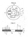
- FIG. 10 is a view showing a back surface of the illumination board
- FIG. 11 is a sectional side view showing the illumination board
- FIG. 12 is a sectional side view showing a state in which the imaging board and the illumination board are placed one on another
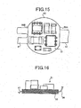
- FIG. 13 is a view showing a front surface of a switch board
- FIG. 14 is a sectional side view showing the switch board
- FIG. 15 is a view showing a back surface of a power supply board
- FIG. 16 is a sectional side view showing the power supply board
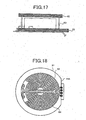
- FIG. 17 is a sectional side view showing a transmission unit
- FIG. 18 is a view showing a back surface of the transmission unit.
- the capsule-type endoscope which is introduced from a mouth of a human or an animal into a body cavity to take the images of the body cavity will be described as an example in the embodiment.
- a capsule-type endoscope 1 includes a folded rigid/flexible board 2 and a capsule 70 which encloses the folded rigid/flexible board 2.
- rigid boards 10, 30, 40, and 50 having rigidity and flexible boards 11, 12, 41, and 54 having foldable flexibility are integrally formed in the rigid/flexible board 2.
- the rigid boards 10, 30, 40, and 50 can be placed one on another by alternately folding the flexible boards 11, 12, and 41 in the opposite directions.
- the rigid board includes the imaging board 10, illumination board 30, the switch board 40, and the power supply board 50.
- the imaging board 10 has a function of imaging the test region in the test subject.
- the illumination board 30 performs a function of illuminating the test region.
- the switch board 40 controls supply of electric power for performing each function.
- the power supply board 50 supplies electric power for performing each function.
- the illumination board 30 and the imaging board 10, the imaging board 10 and the switch board 40, and the switch board 40 and the power supply board 50 are arranged in parallel respectively.
- the imaging board 10, the illumination board 30, the switch board 40, and the power supply board 50 are linearly connected by the flexible boards 11, 12, and 41 made of flexible materials.
- the imaging board 10, the illumination board 30, the switch board 40, and the power supply board 50 are previously integrated with one another.
- a flexible board 54 is extended from a right-side edge portion 50A of the power supply board 50.
- a transmission board 61 which constitutes a transmission unit 60 is electrically connected to the flexible board 54 by a through hole land
- the imaging board 10 is formed in a substantial disc shape.
- a right-side edge portion 10A and a left-side edge portion 10B of the imaging board 10 two sides are formed by linearly cutting out the right-side edge portion 10A and the left-side edge portion 10B in parallel with each other.
- Flexible boards 11 and 12 are extended from the right-side edge portion 10A and the left-side edge portion 10B respectively. Therefore, in folding the flexible boards 11 and 12, the straight-lined right-side edge portion 10A and left-side edge portion 10B can suppress excessive deformations of the flexible boards 11 and 12.
- the right-side edge portion 10A and the left-side edge portion 10B, i.e., the extending directions (two cutout sides) of the flexible boards 11 and 12 become an arrangement reference of electronic components arranged in the imaging board 10.
- an image sensor 13 is previously arranged in a front surface of the imaging board 10 such that the extending directions of the flexible boards 11 and 12 are aligned with a pixel array direction. More particularly, the image sensor 13, which picks up the images of the test region of the test subject, is mounted on the imaging board 10 by a ball grid array.
- the image sensor 13 is formed in a polygonal shape, e.g., in a rectangular shape and includes a solid-state imaging device 13A and a rectangular cover glass 13B.
- An outer circumference of the solid-state imaging device 13A is formed in a rectangular shape having two sets of two parallel sides like CCD (Charge Coupled Diode).
- the cover glass 13B is longitudinally placed on an upper surface of the solid-state imaging device 13A.
- the upper surface of the solid-state imaging device 13A is covered by the cover glass 13B.
- the pixel array direction is set in parallel with the two sides constituting the outer circumferential shape of the image sensor 13.
- the invention is not limited to the embodiment.
- a lens support member 14 is attached onto the upper surface of the cover glass 13B which is of the upper surface of the image sensor 13.
- the lens support member 14 is arranged in close contact to the cover glass 13B.
- the lens support member 14 supports a small-diameter lens 15 and a large-diameter lens 16.
- the illumination light emitted from a later-mentioned illumination unit is reflected from the test region, and the small-diameter lens 15 and the large-diameter lens 16 focus the reflected light onto the image sensor 13 in a form of an optical image.
- the lens support member 14 includes a holder 17 and a lens frame 18.
- the holder 17 is formed in a substantially cylindrical shape as a whole, the holder 17 includes a base portion 17A on one end side and a cylindrical portion 17B on the other end side.
- the base portion 17A abuts against the upper surface (light-receiving surface) of the image sensor 13.
- the cylindrical portion 17B is extended in an upward direction of the drawing.
- a hole portion 17C made in the cylindrical portion 17B pierces through the base portion 17A, and the light incident from above the holder 17 can be guided to the image sensor 13.
- An outer shape of a surface abutting against a lower surface of the base portion 17A, i.e., on the upper surface of the image sensor 13 is formed in substantially square shape having a side substantially equal to a short side of the cover glass 13B.
- An abutting portion 17D which abuts against a side surface of the cover glass 13B is extended downward from two adjacent sides in the lower edge portion.
- the abutting portion 17D abuts against the two adjacent sides of the upper surface of the cover glass 13B. Therefore, the holder 17 is fixed to the cover glass 13B while previously aligned with the cover glass 13B with high accuracy.
- a reinforcement portion 17E having the substantially same shape as the abutting portion 17D is formed while extended from a lower edge portion of the holder 17.
- the cover glass 13B and the holder 17 are fixed to each other with a black adhesive agent 19 after the alignment.
- the black adhesive agent 19 is applied to an exposed surface of the cover glass 13B which is not covered with the holder 17, so that the light incident from the exposed surface can be prevented to project the clear image to the image sensor 13.
- the solid-state imaging device 13A is not limited to CCD.
- CMOS Complementary Metal Oxide Semiconductor
- a lens frame 18 is attached to the holder 17.
- the lens frame 18 holds both the small-diameter lens 15 and the large-diameter lens 16 therein.
- the lens frame 18 is formed in a cylindrical shape, and the lens frame 18 has an outer diameter not larger than an inner diameter of the cylindrical portion 17B of the holder 17.
- a distal-end portion 18A, a small-diameter portion 18B, and a large-diameter portion 18C are formed in an inner circumferential surface of the lens frame 18.
- Step portions 18D and 18E are formed in boundary portions respectively.
- the distal-end portion 18A takes in the incident light which forms an image on the image sensor 13, and the distal-end side of the distal-end portion 18A is formed in a funnel shape.
- the small-diameter lens 15 is fitted in the small-diameter portion 18B.
- the front surface is formed in a flat surface
- the back surface is formed in a convex surface.
- the flat surface portion of the small-diameter lens 15 abuts against the step portion 18D of the distal-end portion 18A, and a circumferential surface portion of the small-diameter lens 15 is fitted in the small-diameter portion 18B.
- a cylindrical spacer 20 and the large-diameter lens 16 are fitted in the large-diameter portion 18C.
- the front surface is formed in a convex surface
- the back surface is formed in a flat surface.
- the spacer 20 separates the small-diameter lens 15 from the large-diameter lens 16 at a predetermined interval.
- a small-diameter portion 18F is formed on one end side in the axial direction
- a large-diameter portion 18G is formed on the other end side, i.e., on the side of the image sensor 13, and a step portion 18H is formed at a boundary portion.
- the large-diameter portion 18G is fitted in the inner circumferential surface of the cylindrical portion 17B of the holder 17, and the lens frame 18 can retractably proceed with respect to the holder 17. Therefore, an imaging position where the image is projected to the image sensor 13 can be adjusted by making the lens frame 18 to retractably proceed, and the holder 17 and the lens frame 18 are fixed to each other with an adhesive agent 21 or the like after the imaging position is adjusted. Accordingly, the lens frame 18 and the lenses held therein are aligned in a direction of an optical axis O and fixed to the image sensor 13 via the holder.17.
- large capacitors 22 are arranged on both sides of the image sensor 13 based on the arrangement of the image sensor 13.
- the large capacitor 22 is an electronic component for a power supply voltage circuit which drives the image sensor 13.
- the outer circumferential shape of the large capacitor 22 is formed in the substantially rectangular shape having the two sets of the two sides parallel to each other. That is, the large capacitor 22 is arranged such that the two sides of the image sensor 13 are parallel to the two sides of the large capacitor 22.
- Other electronic components 23, such as a capacitor and a resistor, having predetermined heights are orderly arranged while avoiding the image sensor 13 and large capacitor 22.
- the electronic components 23 drive the image sensor 13 which is of an electronic component having a predetermined height.
- a microprocessor 24 Digital Signal Processor
- a microprocessor 24 is mounted by flip chip bonding based on the arrangement of the right-side edge portion 10A or the left-side edge portion 10B, i.e., the extending directions of the flexible boards 11 and 12.
- Electronic components 25 such as a capacitor are orderly arranged based on the microprocessor. Therefore, the electronic components 25 can be integrated, which contributes to the downsizing of the capsule-type endoscope 1.
- the microprocessor 24 performs drive control of the capsule-type endoscope 1, signal processing of the image sensor 13, and drive control of the illumination board 30.
- the illumination board 30 is formed in the substantial disc shape, and one side is formed by linearly cutting out a right-side edge portion 30A of the illumination board 30.
- the right-side edge portion 30A is connected to the flexible board 12 extended from the left-side edge portion of the imaging board 10. Therefore, the excessive deformation of the flexible board 12 can be prevented in folding the flexible board 12.
- a through hole 30B which is of a hole piercing through the illumination board 30 is made in a central portion of the illumination board 30.
- the through hole 30B and the right-side edge portion 30A become the arrangement reference of the electronic components which are arranged in the illumination board 30.
- the small-diameter portion 18F of the lens frame 18 is fitted in the through hole 30B when the illumination board 30 is placed on the imaging board 10 with a predetermined interval.
- the through hole 30B has the substantially same shape as the small-diameter portion 18F of the lens frame 18.
- Illumination components 31 are arranged on the front surface of the illumination board 30.
- the illumination component 31 is the illumination units for emitting the illumination light with which the test region of the test subject is illuminated, and the illumination component 31 is one of the illuminating electronic component formed by a light emitting device such as a light emitting diode (Light Emitting Diode) which illuminates the subject in front of the illumination board 30 with the light.
- the illumination components 31 are arranged at positions corresponding to non-display areas (area where display is not performed in later-mentioned observation screen).
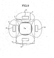
- FIGS. 8 and 9 for a later-mentioned display area and non-display areas in the light-receiving surface of the image sensor 13, an arrangement relationship between the illumination components 31 and the image sensor 13 when viewed from the direction of the optical axis O is described on the same plane by projecting arrangement positions of the illumination components 31 to the direction of the optical axis O.
- the arrangement relationship between the illumination components 31 and the image sensor 13 will be described in detail with reference to FIGS. 8 and 9 .
- an image A obtained by the image sensor 13 has a circular shape. In the circular image A, assuming that a square area is a display area B in the observation screen, the hatched residual area becomes a non-display area C in the observation screen.
- the non-display area C is not displayed on the observation screen, a clear image is not required in the non-display area C. Even if the light from the illumination components 31 has an influence (shown by alternate long and two short-dashed line) on the non-display area C, the non-display area C is not displayed on the observation screen. Accordingly, the illumination components 31 are arranged close to the display area B, and the illumination components 31 are arranged at the positions corresponding to the non-display areas C, i.e., within a range where the light from the illumination components 31 has no influence on the image of the display area B.
- the hatched residual area becomes a non-display area E in the observation screen. Because the non-display area E is also not displayed on the observation screen, a clear image is not required in the non-display area E. Even if the light from the illumination components 31 has an influence (shown by alternate long and two short-dashed line) on the non-display area E, the non-display area E is not displayed on the observation screen.
- the illumination components 31 are arranged close to the display area D, and the illumination components 31 are arranged at the positions corresponding to the non-display areas E, i.e., within a range where the light from the illumination components 31 has no influence on the image of the display area D.
- the image sensor 13 has a light-receiving surface including an effective area (namely, display area on the aforementioned observation screen) and an ineffective area (namely, non-display area on the aforementioned observation screen).
- an effective area namely, display area on the aforementioned observation screen
- an ineffective area namely, non-display area on the aforementioned observation screen.
- An area on the illumination board 30 is defined as a component arrangement unit.
- the area on the illumination board 30 is obtained by projecting the ineffective area of the light-receiving surface onto the illumination board 30 along the optical axis O which is the direction orthogonal to the light-receiving surface of the image sensor 13.
- the illumination components 31 which are of an example of the illuminating electronic component are arranged in the component arrangement unit.
- the illuminating electronic component is not limited to the illumination component 31, but the illuminating electronic component may include an electronic component for driving the illumination component 31.
- the capsule-type endoscope can be downsized in the radial direction.
- the illumination components 31 are not limited to the light emitting diode.
- EL electrophotonescence
- the number of the illumination components 31 is not limited to four.
- a driving electronic component 32, an electronic component 33, and electronic components 34 such as a small capacitor are arranged on the back surface of the illumination board 30.
- the driving electronic component 32 drives the illumination components 31.
- the electronic component 33 stably supplies the voltage to the illumination components 31.
- the tall electronic components such as the driving electronic component 32 and the electronic component 33 for stably supplying the voltage face the low-profile electronic components 23, such as the capacitor and the resistor, which are arranged on the surface (front surface of imaging board 10) facing the illumination board 30 of the imaging board 10.
- the low-profile electronic components 34 such as a small capacitor face the tall and large capacitor 22 which is arranged on the surface (front surface of imaging board 10) facing the illumination board 30 of the imaging board 10.
- the imaging board 10 and the illumination board 30 are arranged by folding the flexible board 12 connecting the imaging board 10 and the illumination board 30, the tall driving electronic component 32, the electronic component 33 for stably supplying the voltage, the low-profile electronic components 34 such as the small capacitor are arranged in the back surface of the illumination board 30, while the tall and large capacitor 22 arranged on the front surface of the imaging board 10, the low-profile small capacitor, and the electronic components 23 such as the resistor are alternately combined.
- an interval between the imaging board 10 and the illumination board 30 can be made narrower than a sum of a height of the tall electronic component arranged on the front surface of the imaging board 10 and the tall electronic component arranged on the back surface of the illumination board 30.
- the flexible board 12 is formed to be longer than the assembled length of the image sensor 13 and the lens support member 14.
- the illumination board 30 having the above configuration is arranged while facing the imaging board 10 with a predetermined interval, the illumination board 30 and the imaging board 10 are fixed to each other while electrically insulated using an adhesive agent 35 having an insulating property.
- the switch board 40 is formed in the substantial disc shape, and a right-side edge portion 40A and a left-side edge portion 40B of the switch board 40 are cut down by parallel two sides.
- the left-side edge portion 40B is connected to the flexible board 11 extended from the right-side edge portion of the imaging board 10, and the flexible board 41 is extended from the right-side edge portion 40A. Therefore, the excessive deformation of the flexible board 41 can be suppressed in folding the flexible board 41.
- the right-side edge portion 40A and the left-side edge portion 40B i.e., the extending directions of the flexible boards 11 and 41 become the arrangement reference of the electronic components arranged in the switch board 40.
- an elliptical hole portion 42 is made in parallel with the two sides of the right-side edge portion 40A and the left-side edge portion 40B.
- a reed switch 43 is arranged on the front surface of the switch board 40 so as to sink into the hole portion 42, which allows a protrusion height of the reed switch 43 to be suppressed on the front surface side of the imaging board 10.
- the reed switch 43 is a latch type switch.
- the reed switch 43 is turned off in the initial state, and the reed switch 43 is turned on by distancing a magnet (not shown) located close to the reed switch 43.
- the electronic components such as a memory 44, an oscillator 45, and MIX 46 are orderly arranged around the reed switch 43.
- Initial values of the microprocessor 24, white balance and variations in color of the solid-state imaging device 13A, a device-specific number of the capsule-type endoscope 1, and the like are stored in the memory 44.
- the oscillator 45 supplies a basic clock to the microprocessor 24.
- the MIX 4.6 is mounted by the flip chip bonding. When an image signal and a clock signal, which are outputted from the microprocessor 24, are transmitted, the MIX 46 serves to mix the image signal and the clock signal into one signal.
- a contact 47 abutting against a positive electrode of a battery is provided on the back surface of the switch board 40.
- the contact 47 is formed with a plate spring.
- the power supply board 50 is formed in the substantial disc shape, and a right-side edge portion 50A and a left-side edge portion 50B of the power supply board 50 are cut down by parallel two sides.
- the left-side edge portion 50B is connected to the flexible board 41 extended from the right-side edge portion 40A of the switch board 40. Therefore, the deformation of the flexible board can be suppressed in folding the flexible board.
- a contact (not shown) abutting against a negative electrode of the battery is provided on the front surface of the power supply board 50, and a DC-DC converter 51 is provided in the back surface of the power supply board 50.
- the DC-DC converter 51 controls the voltage obtained by the battery in order to obtain the constant voltage necessary for the capsule-type endoscope 1.
- plural (three in the embodiment) batteries 52 are sandwiched between the power supply board 50 and the switch board 40, and the plural batteries 52 are integrated while gripped between the switch board 40 and the power supply board 50 by shrinking a cross-sectional heat-shrinkable tubing 53.
- An elliptical slit 41A is formed in the central portion of the flexible board 41, and the flexible board 41 is in close contact with the batteries 52 along the outer circumferences of the batteries 52.
- a button-shaped silver oxide battery whose outer shape is a disc forms the battery 52.
- the plural batteries 52 are connected in series, and the batteries 52 are arranged such that the negative electrode side is orientated toward the power supply board 50.
- the battery 52 is not limited to the silver oxide battery.
- a rechargeable battery and a generating type battery may also be used.
- the flexible board 54 is extended to the right-side edge portion 50A of the power supply board 50, and a transmission unit 60 is connected to the flexible board 54.
- the transmission unit 60 is formed independently of the rigid/flexible board 2, and then the transmission unit 60 is connected to the flexible board 54 by the through hole land.
- the transmission unit 60 includes a transmission board 61 and an antenna board 62.
- the transmission board 61 is formed in the disc shape.
- a right-side edge portion 61A of the transmission board 61 is formed by linearly cutting out the transmission board 61.
- the right-side edge portion 61A becomes the arrangement reference of the electronic components arranged in the transmission board 61, and the electronic components are arranged in the back surface of the transmission board 61 based on the right-side edge portion 61A.
- the antenna board 62 is attached to a terminal 63 vertically provided from the back surface of the transmission board 61, and a substantially spiral antenna pattern 64 is formed in the back surface of the antenna board 62.
- the transmission unit 60 can take out the signal having predetermined frequency, amplitude, and waveform from the signal to which the mixing is already performed by the switch board 40, and the transmission unit 60 can transmit the picked up signal to the outside from the antenna board 62.
- the switch board 40 and the imaging board 10 and the power supply board 50 and transmission unit 60 are arranged with a predetermined interval while facing each other respectively, the switch board 40 and imaging board 10, and the power supply board 50 and transmission unit 60 are fixed while electrically insulated by the adhesive agent 65 having the insulating property.
- the laminated rigid/flexible board 2 constitutes the inside of the capsule-type endoscope 1, and the laminated rigid/flexible board 2 is enclosed by a capsule 70.
- the capsule 70 includes a distal-end cover 71 and a case 72.
- the distal-end cover 71 is formed in a hemispherical dome shape, and the rear side of the distal-end cover 71 is opened.
- the front surface side of the illumination board 30 is covered with the distal-end cover 71.
- the distal-end cover 71 has transparency or translucency.
- the illumination light emitted from the illumination components 31 is transmitted through the distal-end cover 71 to the outside of the capsule 70, and the image illuminated with the illumination light is also transmitted through the distal-end cover 71 to the inside of the capsule 70.
- connection end portion 71A is formed over the circumference of the opened portion of the distal-end cover 71.
- the connection end portion 71A is extended toward the opened direction (toward rear side).
- the connection end portion 71A has a cylindrical shape in which a draft angle does not exist in molding.
- the outer circumferential surface of the connection end portion 71A constitutes a connection surface with the case 72, and an endless protrusion 71B is provided over the circumference of the connection surface.
- the protrusion 71B is provided at an arbitrary position, where the protrusion 71B is separated away from the edge of the connection end portion 71A of the distal-end cover 71, e.g., at the central portion in the overlapping width direction.
- the base end portion from which the connection end portion 71A is extended has a thick portion 71C.
- a cross section is formed thicker than that of the connection end portion 71A or the hemispherical dome shape portion with which the front surface side of the illumination board 30 is covered.
- the thick portion 71C secures strength in the connection end portion 71A of the distal-end cover 71.
- the thick portion 71C prevents a crack of the distal-end cover 71 in the case of accidental dropping.
- an abutting portion 71D is formed in the inner circumferential surface of the base end portion from which the connection end portion 71A is extended.
- the distal-end cover 71 and the folded rigid/flexible board 2 can be positioned at a predetermined positional relationship in the axial direction by causing the illumination board 30 to abut against the abutting portion 71D.
- an inner diameter of the base end portion from which the connection end portion 71A is extended is substantially equal to outer diameters of the illumination board 30 and imaging board 10. Therefore, the distal-end cover 71 and the folded rigid/flexible board 2 can be positioned in the radial direction, the inner circumferential surface of the connection end portion 71A in the distal-end cover 71 abuts against the outer circumferential surface of the illumination board 30, and the connection end portion 71A regulates the inward deformation of the capsule 70.
- the distal-end cover 71 and the case 72 are fixed by injecting the adhesive agent between the inner circumferential surface of the connection end portion 71A in the distal-end cover 71 and the folded rigid/flexible board 2.
- the illumination board 30 of the rigid/flexible board 2 is positioned in the distal-end cover 71.
- the case 72 is a portion with which the folded rigid/flexible board 2 is covered on the rear side of the distal-end cover 71.
- a cylindrical drum portion 72A and a rear-end portion 72B having a substantially hemispherical dome shape are integrally formed, and the front side of the drum portion 72A is opened.
- a connection end portion 72D is formed over the circumference of an opening 72C of the case 72.
- the connection end portion 72D is extended toward the opened direction (toward front side).
- the connection end portion 72D has the cylindrical shape in which the draft angle does not exist in molding.
- the inner circumferential surface of the connection end portion 72D constitutes the connection surface with the distal-end cover 71, and an endless groove 72E is provided over the circumference of the connection surface.
- the groove 72E is provided.according to the position where the protrusion 71B is provided in the distal-end cover 71.
- the overlapping width ranges from about 1 to about 5 mm, and preferably 3 mm.
- the groove 72E is preferably provided in the central portion of the overlapping width.
- the protrusion 71B and groove 72E engage with each other when the distal-end cover 71 and the case 72 overlap each other in the connection surface.
- the engagement between the protrusion 71B and the groove 72E holds the state in which the distal-end cover 71 and the case 72 are connected to each other.
- the protrusion 71B and groove 72E engage with each other to connect the distal-end cover 71 and the case 72, which allows each connection surface to be relatively slid and rotated.
- a resin material 80 is applied to the outer circumferential surface of the folded rigid/flexible board 2, and the adhesive agent is applied to the connection surface of the connection end portion of the distal-end cover 71. Then, the distal-end cover 71 and the case 72 are connected by overlapping the connection surface of the connection end portion of the distal-end cover 71 and the connection surface of the connection end portion of the case 72. Therefore; the gap between the outer circumferential surface of the folded rigid/flexible board 2 and the inner circumferential surface of the capsule is filled with the resin material, and the adhesive agent intrudes between the connection surface of the connection end portion of the distal-end cover 71 and the connection surface of the connection end portion of the case 72.
- the distal-end cover 71 and the case 72 are relatively slid and rotated while connected to each other, which allows the adhesive agent to spread into between the connection surface of the connection end portion of the distal-end cover 71 and the connection surface of the connection end portion of the case 72.
- watertightness is secured between the distal-end cover 71 and the case 72, and the whole of the capsule 70 can be sealed in the watertight manner.
- chamfering is performed to the connection portions of the distal-end cover 71 and the case 72, which emerge on the outer surface of the capsule in the state in which the distal-end cover 71 and the case 72 are connected.
- the chamfering decreases a step which might be generated in the outer surface of the capsule between the distal-end cover 71 and the case 72. Therefore, the case in which something is caught in the step to generate external force separating the distal-end cover 71 and the case 72 can be prevented.
- the distal-end cover 71 is made of a cycloolefin polymer, polycarbonate, acryl, polysulfone, or urethane. Particularly, the cycloolefin polymer or polycarbonate can preferably be used in order to secure optical performances and strength of the distal-end cover 71.
- the case 72 is made of a cycloolefin polymer, polycarbonate, acryl, polysulfone, or urethane. Particularly, polycarbonate can preferably be used in order to secure the strength of the case 72.
- FIG. 19 is a schematic view showing the medical system in which the capsule-type endoscope is used.
- the medical system in which the capsule-type endoscope is used includes the capsule-type endoscope 1 stored in a package 100, a jacket 102 which a patient, i.e., a subject 101 wears, a receiver 103 which is detachably attached to the jacket 102, and a computer 104.
- Antennas 102a, 102b, 102c, and 102d which pick up radio waves transmitted from the antenna board 62 of the capsule-type endoscope 1 are provided in the jacket 102, and the capsule-type endoscope 1 can communicate with a receiver 103 through the antennas 102a to 102d.
- the number of antennas is not limited to the four antennas 102a to 102d shown in FIG. 17 as long as the plural antennas are used.
- the radio wave can be well received at a position depending on the movement of the capsule-type endoscope 1 by the antennas 102a to 102d.
- the position of the capsule-type endoscope 1 in the body cavity can also be detected from the received intensity of each of the antennas 102a to 102d.
- the receiver 103 performs the white balance process to the taken image data sequentially received, and the image data to which the white balance process is already performed is stored in a CompactFlash (registered trademark) memory card (CF memory card) 105.
- the radio wave reception by the receiver 103 is not synchronized with the start of image pick-up by the capsule-type endoscope 1, but the start and the end of the ratio wave reception are controlled by an operation of an input unit of the receiver 103.
- the computer 104 reads from and writes to the CF memory card 105.
- a doctor or a nurse performs image processing to the images of the organs or the like in the patient body, i.e., the test subject, taken by the capsule-type endoscope 1, to display the images on an observation screen (monitor).
- the observation screen has a square shape or an octagonal shape in which the four corners of the square are cut down.
- the capsule-type endoscope 1 is taken out from the package 100.
- the reed switch 43 of the capsule-type endoscope 1 is transferred from the OFF state to the ON state to turn on the main power supply.
- the subject swallows the capsule-type endoscope 1 from the mouth. Therefore, the capsule-type endoscope 1 passes through the gullet and progresses through the body cavity by vermicular movements of alimentary canals.
- the capsule-type endoscope 1 sequentially picks up the images in the body cavity.
- the capsule-type endoscope 1 outputs the radio waves of the taken image sequentially or as needed.
- the antennas 102a to 102d of the jacket 102 pick up the radio waves.
- the radio waves picked up by the antennas 102a to 102d are transmitted to the receiver 103 in the form of the signal.
- the CF memory card 105 in which the taken image data is stored is taken out from the receiver 103, and the CF memory card 105 is inserted into a memory card insertion hole of the computer 104.
- the taken image data stored in the CF memory card 105 is read and stored according to the individual patient.
- the taken image is processed to display the image on the monitor of the computer 104.
- the illumination board 30, the imaging board 10, the switch board 40, and the power supply board 50 are linearly connected in this order by the flexible boards 11, 12, and 41.
- the illumination board 30, the imaging board 10, the switch board 40, and the power supply board 50 may be connected not in a linear manner as far as they are placed in this order when the flexible boards 11, 12, and 41 are folded.
- the illumination board 30, the imaging board 10, the switch board 40, and the power supply board 50 may not always be formed in the straight line as long as the illumination board 30, the imaging board 10, the switch board 40, and the power supply board 50 are located in the same plane.
- the capsule-type endoscope 1 of the embodiment includes the illumination board 30 which is prepared to mount the illuminating electronic components, the illuminating electronic component being necessary to illuminate the test region of the test subject with illumination light; the image sensor 13 which has the light-receiving surface including the effective area (display areas B and D) and the ineffective area (non-display areas C and E), the illumination light reflected from the test region being received to generate the image of the test region in the effective area, the ineffective area not contributing to the image generation; the imaging board 10 which is arranged in parallel with the illumination board 30, the image sensor 13 being mounted on the imaging board 10; and the component arrangement unit in which the illuminating electronic components are arranged, the illuminating electronic components being provided in an area on the illumination board 30, the area on the illumination board 30 being obtained by projecting the ineffective area (non-display areas C and E) in the light-receiving surface of the image sensor 13 to a direction orthogonal to the light-receiving surface of the image sensor. Therefore
- the present invention is useful for the capsule-type endoscope which is introduced into the test subject to observe the test region.
- the present invention is suitable for the capsule-type endoscope which is introduced from the mouth into the body cavity of the test subject to collect the information on the inside of the body cavity by picking up the images of the alimentary canals such as the small intestine and the large intestine with the imaging device.
Description
- The present invention relates to a capsule-type endoscope which is introduced into a test subject to observe a test region.
- In recent years, a capsule-type endoscope has been proposed in the field of an endoscope. The capsule-type endoscope is introduced from a mouth into a body cavity of the test subject. An imaging device in the capsule-type endoscope picks up images of alimentary canals such as the small intestine and the large intestine, whereby the capsule-type endoscope can collect information on the inside of the body cavity. An illumination unit (light emitting diode) and an objective lens are fixed in a front portion of the capsule-type endoscope, whereas a main block to which a circuit board is fixed and an outer casing which houses the main block are provided in a rear portion of the capsule-type endoscope. An image sensor, an electronic component that controls the image sensor, an electronic component for transmission, and a power switch, and the like are fixed to the circuit board, and an antenna board is connected to the circuit board. A battery is incorporated into the circuit board. The outer casing includes a hemispherical transparent cover and a cylindrical cover. A front portion of the main block is covered with the transparent cover, and a rear portion of the main block is covered with the cylindrical cover. A rear-end portion of the cylindrical cover is formed in a hemispherical shape. The circuit board is fixed to the main block, the main block is accommodated in the outer casing, and the capsule-type endoscope is assembled by bonding the transparent cover and the cylindrical cover in a watertight manner (for example, see Patent Document 1).
- Patent Document 1: Japanese Patent Application Laid-Open (JP-A) No.
2001-91860
EP 1 342 447 A2
JP 2003325441 A - Though the capsule-type endoscope has been thus downsized, it is not easily swallowed by the test subject. Therefore, there is a demand of a further downsizing of the capsule-type endoscope, particularly the downsizing in a radial direction of the capsule-type endoscope, while the capsule-type endoscope is also required to maintain conventionally required basic functions, such as flare prevention and prevention of vignetting of an observation object, for the observation of the inside of the test subject.
- It is an object of the present invention to provide a capsule-type endoscope which is smaller than the conventional capsule-type endoscope and easily swallowed by the test subject, while maintaining the conventionally required basic functions.
- To solve the problems as descrebed above and to achieve an object, a capsule-type endoscope according to the present invention is defined by
independent claim 1.
Preferred embodiments of the capsule-type endoscope of the present invention are defined by the dependent claims. - According to the present invention, a capsule-type endoscope includes the features of
independent claim 1.
Therefore, the present invention can provide a capsule-type endoscope which is smaller than the conventional one and easily swallowed by the test subject while maintaining the conventionally required basic functions. -
-
FIG. 1 is a sectional side view showing a configuration of a capsule-type endoscope according to an embodiment of the invention; -
FIG. 2 is a top view showing an unfolded form of a rigid/flexible wiring board shown inFIG. 1 ; -
FIG. 3 is a bottom view showing the unfolded form of the rigid/flexible wiring board shown inFIG. 1 ; -
FIG. 4 is a view showing a front surface of an imaging board; -
FIG. 5 is a sectional side view showing a state in which a lens attachment member is attached to the imaging board; -
FIG. 6 is a view showing a back surface of the imaging board; -
FIG. 7 is a view showing a front surface of an illumination board; -
FIG. 8 is a conceptual drawing explaining a positional relationship between illumination components and an image sensor when viewed from an optical axis direction; -
FIG. 9 is a conceptual drawing explaining the positional relationship between the illumination components and the image sensor when viewed from the optical axis direction; -
FIG. 10 is a view showing a back surface of the illumination board; -
FIG. 11 is a sectional side view showing the illumination board; -
FIG. 12 is a sectional side view showing a state in which the imaging board and the illumination board are placed one on another; -
FIG. 13 is a view showing a front surface of a switch board; -
FIG. 14 is a sectional side view showing the switch board; -
FIG. 15 is a view showing a back surface of a power supply board; -
FIG. 16 is a sectional side view showing the power supply board; -
FIG. 17 is a sectional side view showing a transmission unit; -
FIG. 18 is a view showing a back surface of the transmission unit; and -
FIG. 19 is a schematic view showing a medical system in which the capsule-type endoscope is used. -
- 1
- capsule-type endoscope
- 2
- rigid/flexible board
- 10
- imaging board (rigid board)
- 11
- flexible board
- 12
- flexible board
- 13
- image sensor
- 15
- small-diameter lens
- 16
- large-diameter lens
- 17
- holder
- 18
- lens frame
- 30
- illumination board (rigid board)
- 31
- illuminating component
- 40
- switch board (rigid board)
- 41
- flexible board
- 50
- power supply board (rigid board)
- 54
- flexible board
- 60
- transmission unit
- 70
- capsule
- 71
- distal-end cover
- 72
- case
- 103
- receiver
- 104
- computer
- 105
- memory card
- Exemplary embodiments of a capsule-type endoscope according to the present invention will be described in detail with reference to the accompanying drawings. However, the present invention shall not be limited to the embodiments.
-
FIG. 1 is a sectional side view showing a configuration of a capsule-type endoscope according to an embodiment of the invention,FIG. 2 is a top view showing an unfolded form of a rigid/flexible wiring board shown inFIG. 1 ,FIG. 3 is a bottom view showing the unfolded form of the rigid/flexible wiring board shown inFIG. 1 ,FIG. 4 is a. view showing a front surface of an imaging board,FIG. 5 is a sectional side view showing a state in which a lens attachment member is attached to the imaging board,FIG. 6 is a view showing a back surface of the imaging board,FIG. 7 is a view showing a front surface of an illumination board,FIGS. 8 and9 are conceptual drawings explaining a positional relationship between illumination components and an image sensor when viewed from an optical axis direction,FIG. 10 is a view showing a back surface of the illumination board,FIG. 11 is a sectional side view showing the illumination board,FIG. 12 is a sectional side view showing a state in which the imaging board and the illumination board are placed one on another,FIG. 13 is a view showing a front surface of a switch board,FIG. 14 is a sectional side view showing the switch board,FIG. 15 is a view showing a back surface of a power supply board,FIG. 16 is a sectional side view showing the power supply board,FIG. 17 is a sectional side view showing a transmission unit, andFIG. 18 is a view showing a back surface of the transmission unit. - The capsule-type endoscope which is introduced from a mouth of a human or an animal into a body cavity to take the images of the body cavity will be described as an example in the embodiment.
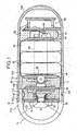
- As shown in
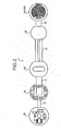
FIG. 1 , a capsule-type endoscope 1 includes a folded rigid/flexible board 2 and acapsule 70 which encloses the folded rigid/flexible board 2. As shown inFIGS. 2 and3 ,rigid boards flexible boards rigid boards flexible boards - The rigid board includes the
imaging board 10,illumination board 30, theswitch board 40, and thepower supply board 50. Theimaging board 10 has a function of imaging the test region in the test subject. Theillumination board 30 performs a function of illuminating the test region. Theswitch board 40 controls supply of electric power for performing each function. Thepower supply board 50 supplies electric power for performing each function. Theillumination board 30 and theimaging board 10, theimaging board 10 and theswitch board 40, and theswitch board 40 and thepower supply board 50 are arranged in parallel respectively. Theimaging board 10, theillumination board 30, theswitch board 40, and thepower supply board 50 are linearly connected by theflexible boards imaging board 10, theillumination board 30, theswitch board 40, and thepower supply board 50 are previously integrated with one another. Aflexible board 54 is extended from a right-side edge portion 50A of thepower supply board 50. Atransmission board 61 which constitutes atransmission unit 60 is electrically connected to theflexible board 54 by a through hole land. - As shown in
FIG. 4 , theimaging board 10 is formed in a substantial disc shape. In a right-side edge portion 10A and a left-side edge portion 10B of theimaging board 10, two sides are formed by linearly cutting out the right-side edge portion 10A and the left-side edge portion 10B in parallel with each other.Flexible boards side edge portion 10A and the left-side edge portion 10B respectively. Therefore, in folding theflexible boards side edge portion 10A and left-side edge portion 10B can suppress excessive deformations of theflexible boards - The right-
side edge portion 10A and the left-side edge portion 10B, i.e., the extending directions (two cutout sides) of theflexible boards imaging board 10. As shown inFIG. 4 , animage sensor 13 is previously arranged in a front surface of theimaging board 10 such that the extending directions of theflexible boards image sensor 13, which picks up the images of the test region of the test subject, is mounted on theimaging board 10 by a ball grid array. Theimage sensor 13 is formed in a polygonal shape, e.g., in a rectangular shape and includes a solid-state imaging device 13A and arectangular cover glass 13B. An outer circumference of the solid-state imaging device 13A is formed in a rectangular shape having two sets of two parallel sides like CCD (Charge Coupled Diode). Thecover glass 13B is longitudinally placed on an upper surface of the solid-state imaging device 13A. The upper surface of the solid-state imaging device 13A is covered by thecover glass 13B. In the embodiment, the pixel array direction is set in parallel with the two sides constituting the outer circumferential shape of theimage sensor 13. However, the invention is not limited to the embodiment. - As shown in
FIG. 5 , alens support member 14 is attached onto the upper surface of thecover glass 13B which is of the upper surface of theimage sensor 13. Thelens support member 14 is arranged in close contact to thecover glass 13B. Thelens support member 14 supports a small-diameter lens 15 and a large-diameter lens 16. The illumination light emitted from a later-mentioned illumination unit is reflected from the test region, and the small-diameter lens 15 and the large-diameter lens 16 focus the reflected light onto theimage sensor 13 in a form of an optical image. Thelens support member 14 includes aholder 17 and alens frame 18. - The
holder 17 is formed in a substantially cylindrical shape as a whole, theholder 17 includes abase portion 17A on one end side and acylindrical portion 17B on the other end side. Thebase portion 17A abuts against the upper surface (light-receiving surface) of theimage sensor 13. Thecylindrical portion 17B is extended in an upward direction of the drawing. Ahole portion 17C made in thecylindrical portion 17B pierces through thebase portion 17A, and the light incident from above theholder 17 can be guided to theimage sensor 13. An outer shape of a surface abutting against a lower surface of thebase portion 17A, i.e., on the upper surface of theimage sensor 13 is formed in substantially square shape having a side substantially equal to a short side of thecover glass 13B. An abuttingportion 17D which abuts against a side surface of thecover glass 13B is extended downward from two adjacent sides in the lower edge portion. - In the
holder 17, while the lower surface of thebase portion 17A abuts against the upper surface of thecover glass 13B, the abuttingportion 17D abuts against the two adjacent sides of the upper surface of thecover glass 13B. Therefore, theholder 17 is fixed to thecover glass 13B while previously aligned with thecover glass 13B with high accuracy. - A
reinforcement portion 17E having the substantially same shape as the abuttingportion 17D is formed while extended from a lower edge portion of theholder 17. Thecover glass 13B and theholder 17 are fixed to each other with a blackadhesive agent 19 after the alignment. The blackadhesive agent 19 is applied to an exposed surface of thecover glass 13B which is not covered with theholder 17, so that the light incident from the exposed surface can be prevented to project the clear image to theimage sensor 13. The solid-state imaging device 13A is not limited to CCD. For example, CMOS (Complementary Metal Oxide Semiconductor) may be used as the solid-state imaging device 13A. - A
lens frame 18 is attached to theholder 17. Thelens frame 18 holds both the small-diameter lens 15 and the large-diameter lens 16 therein. Thelens frame 18 is formed in a cylindrical shape, and thelens frame 18 has an outer diameter not larger than an inner diameter of thecylindrical portion 17B of theholder 17. A distal-end portion 18A, a small-diameter portion 18B, and a large-diameter portion 18C are formed in an inner circumferential surface of thelens frame 18.Step portions - The distal-
end portion 18A takes in the incident light which forms an image on theimage sensor 13, and the distal-end side of the distal-end portion 18A is formed in a funnel shape. The small-diameter lens 15 is fitted in the small-diameter portion 18B. In the small-diameter lens 15 having a large refractive index, the front surface is formed in a flat surface, and the back surface is formed in a convex surface. The flat surface portion of the small-diameter lens 15 abuts against thestep portion 18D of the distal-end portion 18A, and a circumferential surface portion of the small-diameter lens 15 is fitted in the small-diameter portion 18B. Acylindrical spacer 20 and the large-diameter lens 16 are fitted in the large-diameter portion 18C. In the large-diameter lens 16 having a small refractive index, the front surface is formed in a convex surface, and the back surface is formed in a flat surface. Thespacer 20 separates the small-diameter lens 15 from the large-diameter lens 16 at a predetermined interval. - In the outer circumferential surface of the
lens frame 18, a small-diameter portion 18F is formed on one end side in the axial direction, a large-diameter portion 18G is formed on the other end side, i.e., on the side of theimage sensor 13, and astep portion 18H is formed at a boundary portion. The large-diameter portion 18G is fitted in the inner circumferential surface of thecylindrical portion 17B of theholder 17, and thelens frame 18 can retractably proceed with respect to theholder 17. Therefore, an imaging position where the image is projected to theimage sensor 13 can be adjusted by making thelens frame 18 to retractably proceed, and theholder 17 and thelens frame 18 are fixed to each other with anadhesive agent 21 or the like after the imaging position is adjusted. Accordingly, thelens frame 18 and the lenses held therein are aligned in a direction of an optical axis O and fixed to theimage sensor 13 via the holder.17. - As shown in
FIG. 4 , on the front surface of theimaging board 10,large capacitors 22 are arranged on both sides of theimage sensor 13 based on the arrangement of theimage sensor 13. Thelarge capacitor 22 is an electronic component for a power supply voltage circuit which drives theimage sensor 13. The outer circumferential shape of thelarge capacitor 22 is formed in the substantially rectangular shape having the two sets of the two sides parallel to each other. That is, thelarge capacitor 22 is arranged such that the two sides of theimage sensor 13 are parallel to the two sides of thelarge capacitor 22. Otherelectronic components 23, such as a capacitor and a resistor, having predetermined heights are orderly arranged while avoiding theimage sensor 13 andlarge capacitor 22. Theelectronic components 23 drive theimage sensor 13 which is of an electronic component having a predetermined height. - On the other hand, as shown in
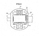
FIG. 6 , in the substantial center of the back surface of theimaging board 10, a microprocessor 24 (Digital Signal Processor) is mounted by flip chip bonding based on the arrangement of the right-side edge portion 10A or the left-side edge portion 10B, i.e., the extending directions of theflexible boards Electronic components 25 such as a capacitor are orderly arranged based on the microprocessor. Therefore, theelectronic components 25 can be integrated, which contributes to the downsizing of the capsule-type endoscope 1. Themicroprocessor 24 performs drive control of the capsule-type endoscope 1, signal processing of theimage sensor 13, and drive control of theillumination board 30. - As shown in
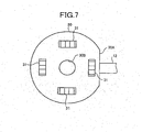
FIG. 7 , theillumination board 30 is formed in the substantial disc shape, and one side is formed by linearly cutting out a right-side edge portion 30A of theillumination board 30. The right-side edge portion 30A is connected to theflexible board 12 extended from the left-side edge portion of theimaging board 10. Therefore, the excessive deformation of theflexible board 12 can be prevented in folding theflexible board 12. - A through
hole 30B which is of a hole piercing through theillumination board 30 is made in a central portion of theillumination board 30. The throughhole 30B and the right-side edge portion 30A become the arrangement reference of the electronic components which are arranged in theillumination board 30. The small-diameter portion 18F of thelens frame 18 is fitted in the throughhole 30B when theillumination board 30 is placed on theimaging board 10 with a predetermined interval. The throughhole 30B has the substantially same shape as the small-diameter portion 18F of thelens frame 18. -
Illumination components 31 are arranged on the front surface of theillumination board 30. Theillumination component 31 is the illumination units for emitting the illumination light with which the test region of the test subject is illuminated, and theillumination component 31 is one of the illuminating electronic component formed by a light emitting device such as a light emitting diode (Light Emitting Diode) which illuminates the subject in front of theillumination board 30 with the light. Theillumination components 31 are arranged at positions corresponding to non-display areas (area where display is not performed in later-mentioned observation screen). - In
FIGS. 8 and9 , for a later-mentioned display area and non-display areas in the light-receiving surface of theimage sensor 13, an arrangement relationship between theillumination components 31 and theimage sensor 13 when viewed from the direction of the optical axis O is described on the same plane by projecting arrangement positions of theillumination components 31 to the direction of the optical axis O. The arrangement relationship between theillumination components 31 and theimage sensor 13 will be described in detail with reference toFIGS. 8 and9 . As shown inFIG. 8 , an image A obtained by theimage sensor 13 has a circular shape. In the circular image A, assuming that a square area is a display area B in the observation screen, the hatched residual area becomes a non-display area C in the observation screen. Because the non-display area C is not displayed on the observation screen, a clear image is not required in the non-display area C. Even if the light from theillumination components 31 has an influence (shown by alternate long and two short-dashed line) on the non-display area C, the non-display area C is not displayed on the observation screen. Accordingly, theillumination components 31 are arranged close to the display area B, and theillumination components 31 are arranged at the positions corresponding to the non-display areas C, i.e., within a range where the light from theillumination components 31 has no influence on the image of the display area B. - As shown in
FIG. 9 , assuming that an octagonal area where corner portions of the square are cut down is a display area D, the hatched residual area becomes a non-display area E in the observation screen. Because the non-display area E is also not displayed on the observation screen, a clear image is not required in the non-display area E. Even if the light from theillumination components 31 has an influence (shown by alternate long and two short-dashed line) on the non-display area E, the non-display area E is not displayed on the observation screen. Accordingly, theillumination components 31 are arranged close to the display area D, and theillumination components 31 are arranged at the positions corresponding to the non-display areas E, i.e., within a range where the light from theillumination components 31 has no influence on the image of the display area D. - In other words, in both the cases of
FIGS. 8 and9 , theimage sensor 13 has a light-receiving surface including an effective area (namely, display area on the aforementioned observation screen) and an ineffective area (namely, non-display area on the aforementioned observation screen). In the effective area, theimage sensor 13 receives the illumination light reflected from the test region, and theimage sensor 13 generates the image of the test region. The ineffective area does not contribute to the image generation. An area on theillumination board 30 is defined as a component arrangement unit. The area on theillumination board 30 is obtained by projecting the ineffective area of the light-receiving surface onto theillumination board 30 along the optical axis O which is the direction orthogonal to the light-receiving surface of theimage sensor 13. Theillumination components 31 which are of an example of the illuminating electronic component are arranged in the component arrangement unit. - As shown in
FIG. 1 , because a predetermined visual field range based on a predetermined view angle α is formed by the lenses (small-diameter lens 15 and large-diameter lens 16) which are supported by thelens frame 18, it is also necessary to arrange the illuminating electronic component in consideration of the view angle α. That is, from the viewpoint of length in a lengthwise direction, theillumination components 31 which are of the illuminating electronic component are arranged out of the visual field range which is formed by the lenses. The illuminating electronic component is not limited to theillumination component 31, but the illuminating electronic component may include an electronic component for driving theillumination component 31. - When the
illumination components 31 are arranged in the above-described manner, a distance between the optical axis O and theillumination components 31 can be shortened (L1 for L2) as compared with the case (shown by alternate long and two short-dashed line inFIG. 8 ) where theillumination components 31 are arranged so as not to have an influence on the obtained image irrespective of the display areas Band D and non-display areas C and E. Therefore, the capsule-type endoscope can be downsized in the radial direction. Theillumination components 31 are not limited to the light emitting diode. For example, EL (electroluminescence) may be used as theillumination components 31. The number of theillumination components 31 is not limited to four. - As shown in
FIGS. 10 and 11 , a drivingelectronic component 32, anelectronic component 33, andelectronic components 34 such as a small capacitor are arranged on the back surface of theillumination board 30. The drivingelectronic component 32 drives theillumination components 31. Theelectronic component 33 stably supplies the voltage to theillumination components 31. - As shown in
FIG. 12 , in the case where theimaging board 10 and theillumination board 30 are placed one on another with a predetermined interval by folding theflexible board 12 connecting theimaging board 10 and theillumination board 30, the tall electronic components such as the drivingelectronic component 32 and theelectronic component 33 for stably supplying the voltage face the low-profileelectronic components 23, such as the capacitor and the resistor, which are arranged on the surface (front surface of imaging board 10) facing theillumination board 30 of theimaging board 10. - On the other hand, in the case where the
imaging board 10 and theillumination board 30 are placed one on another by folding theflexible board 12 connecting theimaging board 10 and theillumination board 30, the low-profileelectronic components 34 such as a small capacitor face the tall andlarge capacitor 22 which is arranged on the surface (front surface of imaging board 10) facing theillumination board 30 of theimaging board 10. - That is, in the rigid/flexible board 2 in which the
imaging board 10 and theillumination board 30 are arranged by folding theflexible board 12 connecting theimaging board 10 and theillumination board 30, the tall drivingelectronic component 32, theelectronic component 33 for stably supplying the voltage, the low-profileelectronic components 34 such as the small capacitor are arranged in the back surface of theillumination board 30, while the tall andlarge capacitor 22 arranged on the front surface of theimaging board 10, the low-profile small capacitor, and theelectronic components 23 such as the resistor are alternately combined. - Therefore, an interval between the
imaging board 10 and theillumination board 30 can be made narrower than a sum of a height of the tall electronic component arranged on the front surface of theimaging board 10 and the tall electronic component arranged on the back surface of theillumination board 30. Theflexible board 12 is formed to be longer than the assembled length of theimage sensor 13 and thelens support member 14. - After the
illumination board 30 having the above configuration is arranged while facing theimaging board 10 with a predetermined interval, theillumination board 30 and theimaging board 10 are fixed to each other while electrically insulated using anadhesive agent 35 having an insulating property. - As shown in
FIGS. 13 and 14 , similarly to theimaging board 10, theswitch board 40 is formed in the substantial disc shape, and a right-side edge portion 40A and a left-side edge portion 40B of theswitch board 40 are cut down by parallel two sides. The left-side edge portion 40B is connected to theflexible board 11 extended from the right-side edge portion of theimaging board 10, and theflexible board 41 is extended from the right-side edge portion 40A. Therefore, the excessive deformation of theflexible board 41 can be suppressed in folding theflexible board 41. - The right-
side edge portion 40A and the left-side edge portion 40B, i.e., the extending directions of theflexible boards switch board 40. In the central portion of theswitch board 40, anelliptical hole portion 42 is made in parallel with the two sides of the right-side edge portion 40A and the left-side edge portion 40B. - A
reed switch 43 is arranged on the front surface of theswitch board 40 so as to sink into thehole portion 42, which allows a protrusion height of thereed switch 43 to be suppressed on the front surface side of theimaging board 10. Thereed switch 43 is a latch type switch. Thereed switch 43 is turned off in the initial state, and thereed switch 43 is turned on by distancing a magnet (not shown) located close to thereed switch 43. The electronic components such as amemory 44, anoscillator 45, andMIX 46 are orderly arranged around thereed switch 43. - Initial values of the
microprocessor 24, white balance and variations in color of the solid-state imaging device 13A, a device-specific number of the capsule-type endoscope 1, and the like are stored in thememory 44. Theoscillator 45 supplies a basic clock to themicroprocessor 24. The MIX 4.6 is mounted by the flip chip bonding. When an image signal and a clock signal, which are outputted from themicroprocessor 24, are transmitted, theMIX 46 serves to mix the image signal and the clock signal into one signal. As shown inFIG. 1 , acontact 47 abutting against a positive electrode of a battery is provided on the back surface of theswitch board 40. Thecontact 47 is formed with a plate spring. - As shown in
FIGS. 15 and 16 , thepower supply board 50 is formed in the substantial disc shape, and a right-side edge portion 50A and a left-side edge portion 50B of thepower supply board 50 are cut down by parallel two sides. The left-side edge portion 50B is connected to theflexible board 41 extended from the right-side edge portion 40A of theswitch board 40. Therefore, the deformation of the flexible board can be suppressed in folding the flexible board. A contact (not shown) abutting against a negative electrode of the battery is provided on the front surface of thepower supply board 50, and a DC-DC converter 51 is provided in the back surface of thepower supply board 50. The DC-DC converter 51 controls the voltage obtained by the battery in order to obtain the constant voltage necessary for the capsule-type endoscope 1. - As shown in
FIG. 1 , plural (three in the embodiment)batteries 52 are sandwiched between thepower supply board 50 and theswitch board 40, and theplural batteries 52 are integrated while gripped between theswitch board 40 and thepower supply board 50 by shrinking a cross-sectional heat-shrinkable tubing 53. Anelliptical slit 41A is formed in the central portion of theflexible board 41, and theflexible board 41 is in close contact with thebatteries 52 along the outer circumferences of thebatteries 52. A button-shaped silver oxide battery whose outer shape is a disc forms thebattery 52. Theplural batteries 52 are connected in series, and thebatteries 52 are arranged such that the negative electrode side is orientated toward thepower supply board 50. Thebattery 52 is not limited to the silver oxide battery. For example, a rechargeable battery and a generating type battery may also be used. - The
flexible board 54 is extended to the right-side edge portion 50A of thepower supply board 50, and atransmission unit 60 is connected to theflexible board 54. Thetransmission unit 60 is formed independently of the rigid/flexible board 2, and then thetransmission unit 60 is connected to theflexible board 54 by the through hole land. - As shown in
FIGS. 17 and 18 , thetransmission unit 60 includes atransmission board 61 and anantenna board 62. Thetransmission board 61 is formed in the disc shape. A right-side edge portion 61A of thetransmission board 61 is formed by linearly cutting out thetransmission board 61. The right-side edge portion 61A becomes the arrangement reference of the electronic components arranged in thetransmission board 61, and the electronic components are arranged in the back surface of thetransmission board 61 based on the right-side edge portion 61A. Theantenna board 62 is attached to a terminal 63 vertically provided from the back surface of thetransmission board 61, and a substantiallyspiral antenna pattern 64 is formed in the back surface of theantenna board 62. Thetransmission unit 60 can take out the signal having predetermined frequency, amplitude, and waveform from the signal to which the mixing is already performed by theswitch board 40, and thetransmission unit 60 can transmit the picked up signal to the outside from theantenna board 62. - As shown in
FIG. 1 , after theswitch board 40 and theimaging board 10, and thepower supply board 50 andtransmission unit 60 are arranged with a predetermined interval while facing each other respectively, theswitch board 40 andimaging board 10, and thepower supply board 50 andtransmission unit 60 are fixed while electrically insulated by theadhesive agent 65 having the insulating property. - The laminated rigid/flexible board 2 constitutes the inside of the capsule-
type endoscope 1, and the laminated rigid/flexible board 2 is enclosed by acapsule 70. Thecapsule 70 includes a distal-end cover 71 and a case 72. - The distal-end cover 71 is formed in a hemispherical dome shape, and the rear side of the distal-end cover 71 is opened. The front surface side of the
illumination board 30 is covered with the distal-end cover 71. The distal-end cover 71 has transparency or translucency. The illumination light emitted from theillumination components 31 is transmitted through the distal-end cover 71 to the outside of thecapsule 70, and the image illuminated with the illumination light is also transmitted through the distal-end cover 71 to the inside of thecapsule 70. - A
connection end portion 71A is formed over the circumference of the opened portion of the distal-end cover 71. Theconnection end portion 71A is extended toward the opened direction (toward rear side). Theconnection end portion 71A has a cylindrical shape in which a draft angle does not exist in molding. The outer circumferential surface of theconnection end portion 71A constitutes a connection surface with the case 72, and an endless protrusion 71B is provided over the circumference of the connection surface. In an overlapping width of the connection surface, the protrusion 71B is provided at an arbitrary position, where the protrusion 71B is separated away from the edge of theconnection end portion 71A of the distal-end cover 71, e.g., at the central portion in the overlapping width direction. - As shown in
FIG. 1 , in the distal-end cover 71, the base end portion from which theconnection end portion 71A is extended has a thick portion 71C. In the thick portion 71C, a cross section is formed thicker than that of theconnection end portion 71A or the hemispherical dome shape portion with which the front surface side of theillumination board 30 is covered. The thick portion 71C secures strength in theconnection end portion 71A of the distal-end cover 71. For example, the thick portion 71C prevents a crack of the distal-end cover 71 in the case of accidental dropping. - In the distal-end cover 71, an abutting
portion 71D is formed in the inner circumferential surface of the base end portion from which theconnection end portion 71A is extended. The distal-end cover 71 and the folded rigid/flexible board 2 can be positioned at a predetermined positional relationship in the axial direction by causing theillumination board 30 to abut against the abuttingportion 71D. - In the distal-end cover 71, an inner diameter of the base end portion from which the
connection end portion 71A is extended is substantially equal to outer diameters of theillumination board 30 andimaging board 10. Therefore, the distal-end cover 71 and the folded rigid/flexible board 2 can be positioned in the radial direction, the inner circumferential surface of theconnection end portion 71A in the distal-end cover 71 abuts against the outer circumferential surface of theillumination board 30, and theconnection end portion 71A regulates the inward deformation of thecapsule 70. - In the case where the folded rigid/flexible board 2 is accommodated inside the
capsule 70 by connecting the distal-end cover 71 and the case 72, the distal-end cover 71 and the case 72 are fixed by injecting the adhesive agent between the inner circumferential surface of theconnection end portion 71A in the distal-end cover 71 and the folded rigid/flexible board 2. Thus, when the folded rigid/flexible board 2 is fixed to the distal-end cover 71, theillumination board 30 of the rigid/flexible board 2 is positioned in the distal-end cover 71. - The case 72 is a portion with which the folded rigid/flexible board 2 is covered on the rear side of the distal-end cover 71. In the case 72, a cylindrical drum portion 72A and a rear-
end portion 72B having a substantially hemispherical dome shape are integrally formed, and the front side of the drum portion 72A is opened. A connection end portion 72D is formed over the circumference of anopening 72C of the case 72. The connection end portion 72D is extended toward the opened direction (toward front side). The connection end portion 72D has the cylindrical shape in which the draft angle does not exist in molding. The inner circumferential surface of the connection end portion 72D constitutes the connection surface with the distal-end cover 71, and anendless groove 72E is provided over the circumference of the connection surface. Thegroove 72E is provided.according to the position where the protrusion 71B is provided in the distal-end cover 71. The overlapping width ranges from about 1 to about 5 mm, and preferably 3 mm. Thegroove 72E is preferably provided in the central portion of the overlapping width. - The protrusion 71B and groove 72E engage with each other when the distal-end cover 71 and the case 72 overlap each other in the connection surface. Thus, the engagement between the protrusion 71B and the
groove 72E holds the state in which the distal-end cover 71 and the case 72 are connected to each other. Because the protrusion 71B is provided over the circumference of the connection surface while thegroove 72E is provided over the circumference of the connection surface, the protrusion 71B and groove 72E engage with each other to connect the distal-end cover 71 and the case 72, which allows each connection surface to be relatively slid and rotated. - A
resin material 80 is applied to the outer circumferential surface of the folded rigid/flexible board 2, and the adhesive agent is applied to the connection surface of the connection end portion of the distal-end cover 71. Then, the distal-end cover 71 and the case 72 are connected by overlapping the connection surface of the connection end portion of the distal-end cover 71 and the connection surface of the connection end portion of the case 72. Therefore; the gap between the outer circumferential surface of the folded rigid/flexible board 2 and the inner circumferential surface of the capsule is filled with the resin material, and the adhesive agent intrudes between the connection surface of the connection end portion of the distal-end cover 71 and the connection surface of the connection end portion of the case 72. Then, the distal-end cover 71 and the case 72 are relatively slid and rotated while connected to each other, which allows the adhesive agent to spread into between the connection surface of the connection end portion of the distal-end cover 71 and the connection surface of the connection end portion of the case 72. As a result, watertightness is secured between the distal-end cover 71 and the case 72, and the whole of thecapsule 70 can be sealed in the watertight manner. - As shown in
FIG. 1 . chamfering is performed to the connection portions of the distal-end cover 71 and the case 72, which emerge on the outer surface of the capsule in the state in which the distal-end cover 71 and the case 72 are connected. The chamfering decreases a step which might be generated in the outer surface of the capsule between the distal-end cover 71 and the case 72. Therefore, the case in which something is caught in the step to generate external force separating the distal-end cover 71 and the case 72 can be prevented. - The distal-end cover 71 is made of a cycloolefin polymer, polycarbonate, acryl, polysulfone, or urethane. Particularly, the cycloolefin polymer or polycarbonate can preferably be used in order to secure optical performances and strength of the distal-end cover 71. The case 72 is made of a cycloolefin polymer, polycarbonate, acryl, polysulfone, or urethane. Particularly, polycarbonate can preferably be used in order to secure the strength of the case 72.
- Then, a medical system in which the above described capsule-type endoscope is used will be described.
FIG. 19 is a schematic view showing the medical system in which the capsule-type endoscope is used. - As shown in
FIG. 19 , the medical system in which the capsule-type endoscope is used includes the capsule-type endoscope 1 stored in apackage 100, ajacket 102 which a patient, i.e., a subject 101 wears, areceiver 103 which is detachably attached to thejacket 102, and acomputer 104. -
Antennas antenna board 62 of the capsule-type endoscope 1 are provided in thejacket 102, and the capsule-type endoscope 1 can communicate with areceiver 103 through theantennas 102a to 102d. The number of antennas is not limited to the fourantennas 102a to 102d shown inFIG. 17 as long as the plural antennas are used. The radio wave can be well received at a position depending on the movement of the capsule-type endoscope 1 by theantennas 102a to 102d. The position of the capsule-type endoscope 1 in the body cavity can also be detected from the received intensity of each of theantennas 102a to 102d. - The
receiver 103 performs the white balance process to the taken image data sequentially received, and the image data to which the white balance process is already performed is stored in a CompactFlash (registered trademark) memory card (CF memory card) 105. The radio wave reception by thereceiver 103 is not synchronized with the start of image pick-up by the capsule-type endoscope 1, but the start and the end of the ratio wave reception are controlled by an operation of an input unit of thereceiver 103. - The
computer 104 reads from and writes to theCF memory card 105. In thecomputer 104, a doctor or a nurse (examiner) performs image processing to the images of the organs or the like in the patient body, i.e., the test subject, taken by the capsule-type endoscope 1, to display the images on an observation screen (monitor). The observation screen has a square shape or an octagonal shape in which the four corners of the square are cut down. - A schematic operation of the medical system will be described below. Before diagnostic examination is started, the capsule-
type endoscope 1 is taken out from thepackage 100. By doing this, thereed switch 43 of the capsule-type endoscope 1 is transferred from the OFF state to the ON state to turn on the main power supply. Then, the subject swallows the capsule-type endoscope 1 from the mouth. Therefore, the capsule-type endoscope 1 passes through the gullet and progresses through the body cavity by vermicular movements of alimentary canals. The capsule-type endoscope 1 sequentially picks up the images in the body cavity. The capsule-type endoscope 1 outputs the radio waves of the taken image sequentially or as needed. Theantennas 102a to 102d of thejacket 102 pick up the radio waves. The radio waves picked up by theantennas 102a to 102d are transmitted to thereceiver 103 in the form of the signal. When the observation (diagnostic examination) of the subject 101 by the capsule-type endoscope 1 is completed, theCF memory card 105 in which the taken image data is stored is taken out from thereceiver 103, and theCF memory card 105 is inserted into a memory card insertion hole of thecomputer 104. In thecomputer 104, the taken image data stored in theCF memory card 105 is read and stored according to the individual patient. In making the diagnosis, the taken image is processed to display the image on the monitor of thecomputer 104. - In the capsule-
type endoscope 1 of the above embodiment, theillumination board 30, theimaging board 10, theswitch board 40, and thepower supply board 50 are linearly connected in this order by theflexible boards illumination board 30, theimaging board 10, theswitch board 40, and thepower supply board 50 may be connected not in a linear manner as far as they are placed in this order when theflexible boards illumination board 30, theimaging board 10, theswitch board 40, and thepower supply board 50 may not always be formed in the straight line as long as theillumination board 30, theimaging board 10, theswitch board 40, and thepower supply board 50 are located in the same plane. - Thus, the capsule-
type endoscope 1 of the embodiment includes theillumination board 30 which is prepared to mount the illuminating electronic components, the illuminating electronic component being necessary to illuminate the test region of the test subject with illumination light; theimage sensor 13 which has the light-receiving surface including the effective area (display areas B and D) and the ineffective area (non-display areas C and E), the illumination light reflected from the test region being received to generate the image of the test region in the effective area, the ineffective area not contributing to the image generation; theimaging board 10 which is arranged in parallel with theillumination board 30, theimage sensor 13 being mounted on theimaging board 10; and the component arrangement unit in which the illuminating electronic components are arranged, the illuminating electronic components being provided in an area on theillumination board 30, the area on theillumination board 30 being obtained by projecting the ineffective area (non-display areas C and E) in the light-receiving surface of theimage sensor 13 to a direction orthogonal to the light-receiving surface of the image sensor. Therefore, the capsule-type endoscope of the present invention can be smaller than the conventional one while maintaining the conventionally required basic functions, and the subject can easily swallow the capsule-type endoscope. - The present invention is useful for the capsule-type endoscope which is introduced into the test subject to observe the test region. Particularly, the present invention is suitable for the capsule-type endoscope which is introduced from the mouth into the body cavity of the test subject to collect the information on the inside of the body cavity by picking up the images of the alimentary canals such as the small intestine and the large intestine with the imaging device.
Claims (5)
- A capsule-type endoscope (1) comprising:an illumination board (30) which is prepared to mount an illuminating electronic component (31) necessary to illuminate a test region of a test subject with illumination light;an image sensor (13) which has a light-receiving surface including a display area (B; D) and a non-display area (C; E), the illumination light reflected from the test region being received to generate an image of the test region in the display area, the display area (B; D) being an area that is displayed on an observation screen for observing the generated image and the non-display area (C; E) being an area that is a part of the image obtained by the image sensor but that is not displayed on the observation screen;an imaging board (10) which is arranged in parallel with the illumination board (30), the image sensor (13) being mounted on the imaging board (10); anda component arrangement unit in which the illuminating electronic component (31) is arranged, the illuminating electronic component being provided in an area on the illumination board (30), the area on the illumination board (30) being obtained by projecting the area not contributing to the image generation in the light-receiving surface of the image sensor (13) to a direction orthogonal to the light-receiving surface of the image sensor (13),wherein the illumination board (30) and the imaging board (10) are formed of rigid boards and electrically connected to each other through a flexible board,wherein the illuminating electronic component (31) is arranged on the component arrangement unit such that the light from the illuminating electronic component (31) has no influence on the image of the display area (B; D).
- The capsule-type endoscope (1) according to claim 1, further comprising
a lens(15, 16) which forms a visual field range based on a predetermined view angle, the lens focusing the illumination light reflected from the test region onto the light-receiving surface of the image sensor (13) in a form of an optical image of the test region,
wherein the illuminating electronic component (31) is arranged in the component arrangement unit so as to be arranged out of the visual field range formed by the lens (15, 16). - The capsule-type endoscope (1) according to claims 1 or 2, wherein
the illuminating electronic component (31) includes a light emitting device which emits the illumination light, the test region of the test subject being illuminated with the illumination light. - The capsule-type endoscope (1) according to claim 1, wherein
when the imaging board (10) and the illumination board (30) are arranged in the capsule-type endoscope (1) by folding the flexible board connecting the imaging board (10) and the illumination board (30), a tall electronic component discposed on a front surface of the imaging board (10) faces a small-profile electronic component disposed on a back surface of the illumination board (30) and a small-profile electronic component disposed on the front surface of the imaging board (10) faces a tall electronic component disposed on the back surface of the illumination board (30). - The capsule-type endoscope (1) according to claim 1, wherein the imaging board (10) and the illumination board (30) are rigid boards in a substantially disk shape.
Applications Claiming Priority (2)
| Application Number | Priority Date | Filing Date | Title |
|---|---|---|---|
| JP2004017137A JP2005205077A (en) | 2004-01-26 | 2004-01-26 | Capsule type endoscope |
| PCT/JP2005/000869 WO2005070280A1 (en) | 2004-01-26 | 2005-01-24 | Capsule-type endoscope |
Publications (3)
| Publication Number | Publication Date |
|---|---|
| EP1709899A1 EP1709899A1 (en) | 2006-10-11 |
| EP1709899A4 EP1709899A4 (en) | 2007-07-18 |
| EP1709899B1 true EP1709899B1 (en) | 2013-03-06 |
Family
ID=34805519
Family Applications (1)
| Application Number | Title | Priority Date | Filing Date |
|---|---|---|---|
| EP05704050A Expired - Fee Related EP1709899B1 (en) | 2004-01-26 | 2005-01-24 | Capsule-type endoscope |
Country Status (5)
| Country | Link |
|---|---|
| US (1) | US8348835B2 (en) |
| EP (1) | EP1709899B1 (en) |
| JP (1) | JP2005205077A (en) |
| AU (1) | AU2005206035B2 (en) |
| WO (1) | WO2005070280A1 (en) |
Families Citing this family (48)
| Publication number | Priority date | Publication date | Assignee | Title |
|---|---|---|---|---|
| US20060169294A1 (en) * | 2004-12-15 | 2006-08-03 | Kaler Karan V | Inertial navigation method and apparatus for wireless bolus transit monitoring in gastrointestinal tract |
| US8235055B2 (en) * | 2005-01-11 | 2012-08-07 | Uti Limited Partnership | Magnetic levitation of intraluminal microelectronic capsule |
| US8852083B2 (en) * | 2005-02-04 | 2014-10-07 | Uti Limited Partnership | Self-stabilized encapsulated imaging system |
| US20060231110A1 (en) * | 2005-03-24 | 2006-10-19 | Mintchev Martin P | Ingestible capsule for esophageal monitoring |
| WO2007125918A1 (en) * | 2006-04-25 | 2007-11-08 | Olympus Medical Systems Corp. | Encapsulated endoscope |
| JP2007289528A (en) * | 2006-04-26 | 2007-11-08 | Olympus Medical Systems Corp | Antenna unit and receiver |
| JP4682158B2 (en) * | 2007-01-16 | 2011-05-11 | オリンパスメディカルシステムズ株式会社 | Imaging device |
| JP2009082503A (en) * | 2007-09-28 | 2009-04-23 | Fujifilm Corp | Imaging device and endoscope equipped with the same |
| JP5042940B2 (en) * | 2008-08-08 | 2012-10-03 | シャープ株式会社 | Solid-state imaging device and electronic apparatus including the same |
| JP5047902B2 (en) * | 2008-08-08 | 2012-10-10 | シャープ株式会社 | Solid-state imaging device and electronic apparatus including the same |
| WO2012120507A1 (en) | 2011-02-07 | 2012-09-13 | Peermedical Ltd. | Multi-element cover for a multi-camera endoscope |
| US10165929B2 (en) | 2009-06-18 | 2019-01-01 | Endochoice, Inc. | Compact multi-viewing element endoscope system |
| US11864734B2 (en) | 2009-06-18 | 2024-01-09 | Endochoice, Inc. | Multi-camera endoscope |
| US9872609B2 (en) | 2009-06-18 | 2018-01-23 | Endochoice Innovation Center Ltd. | Multi-camera endoscope |
| US9402533B2 (en) | 2011-03-07 | 2016-08-02 | Endochoice Innovation Center Ltd. | Endoscope circuit board assembly |
| US9101287B2 (en) | 2011-03-07 | 2015-08-11 | Endochoice Innovation Center Ltd. | Multi camera endoscope assembly having multiple working channels |
| US11278190B2 (en) | 2009-06-18 | 2022-03-22 | Endochoice, Inc. | Multi-viewing element endoscope |
| US8926502B2 (en) | 2011-03-07 | 2015-01-06 | Endochoice, Inc. | Multi camera endoscope having a side service channel |
| US9706903B2 (en) | 2009-06-18 | 2017-07-18 | Endochoice, Inc. | Multiple viewing elements endoscope system with modular imaging units |
| EP3811847A1 (en) | 2009-06-18 | 2021-04-28 | EndoChoice, Inc. | Multi-camera endoscope |
| US9642513B2 (en) | 2009-06-18 | 2017-05-09 | Endochoice Inc. | Compact multi-viewing element endoscope system |
| US11547275B2 (en) | 2009-06-18 | 2023-01-10 | Endochoice, Inc. | Compact multi-viewing element endoscope system |
| US9492063B2 (en) | 2009-06-18 | 2016-11-15 | Endochoice Innovation Center Ltd. | Multi-viewing element endoscope |
| US9101268B2 (en) | 2009-06-18 | 2015-08-11 | Endochoice Innovation Center Ltd. | Multi-camera endoscope |
| US9901244B2 (en) | 2009-06-18 | 2018-02-27 | Endochoice, Inc. | Circuit board assembly of a multiple viewing elements endoscope |
| US9713417B2 (en) | 2009-06-18 | 2017-07-25 | Endochoice, Inc. | Image capture assembly for use in a multi-viewing elements endoscope |
| EP2312919B1 (en) * | 2009-10-08 | 2013-03-13 | Sick Ag | Optoelectronic sensor |
| EP2848190B1 (en) * | 2010-09-08 | 2016-11-02 | Covidien LP | Catheter with imaging assembly |
| US9560953B2 (en) | 2010-09-20 | 2017-02-07 | Endochoice, Inc. | Operational interface in a multi-viewing element endoscope |
| EP3718466B1 (en) | 2010-09-20 | 2023-06-07 | EndoChoice, Inc. | Endoscope distal section comprising a unitary fluid channeling component |
| CN103403605A (en) | 2010-10-28 | 2013-11-20 | 恩多巧爱思创新中心有限公司 | Optical systems for multi-sensor endoscopes |
| JP6054874B2 (en) | 2010-12-09 | 2016-12-27 | エンドチョイス イノベーション センター リミテッド | Flexible electronic circuit board for multi-camera endoscope |
| EP3420886B8 (en) | 2010-12-09 | 2020-07-15 | EndoChoice, Inc. | Flexible electronic circuit board multi-camera endoscope |
| US11889986B2 (en) | 2010-12-09 | 2024-02-06 | Endochoice, Inc. | Flexible electronic circuit board for a multi-camera endoscope |
| JP5913870B2 (en) * | 2011-08-31 | 2016-04-27 | オリンパス株式会社 | Capsule medical device |
| JP5806557B2 (en) * | 2011-08-31 | 2015-11-10 | オリンパス株式会社 | Capsule endoscope |
| EP3659491A1 (en) | 2011-12-13 | 2020-06-03 | EndoChoice Innovation Center Ltd. | Removable tip endoscope |
| EP2604172B1 (en) | 2011-12-13 | 2015-08-12 | EndoChoice Innovation Center Ltd. | Rotatable connector for an endoscope |
| US9560954B2 (en) | 2012-07-24 | 2017-02-07 | Endochoice, Inc. | Connector for use with endoscope |
| US10045713B2 (en) | 2012-08-16 | 2018-08-14 | Rock West Medical Devices, Llc | System and methods for triggering a radiofrequency transceiver in the human body |
| USD735343S1 (en) | 2012-09-07 | 2015-07-28 | Covidien Lp | Console |
| US9198835B2 (en) | 2012-09-07 | 2015-12-01 | Covidien Lp | Catheter with imaging assembly with placement aid and related methods therefor |
| US9517184B2 (en) | 2012-09-07 | 2016-12-13 | Covidien Lp | Feeding tube with insufflation device and related methods therefor |
| US9993142B2 (en) | 2013-03-28 | 2018-06-12 | Endochoice, Inc. | Fluid distribution device for a multiple viewing elements endoscope |
| US9986899B2 (en) | 2013-03-28 | 2018-06-05 | Endochoice, Inc. | Manifold for a multiple viewing elements endoscope |
| US10499794B2 (en) | 2013-05-09 | 2019-12-10 | Endochoice, Inc. | Operational interface in a multi-viewing element endoscope |
| US10945635B2 (en) | 2013-10-22 | 2021-03-16 | Rock West Medical Devices, Llc | Nearly isotropic dipole antenna system |
| JP6868153B2 (en) * | 2018-03-07 | 2021-05-12 | Phcホールディングス株式会社 | Communication device |
Family Cites Families (15)
| Publication number | Priority date | Publication date | Assignee | Title |
|---|---|---|---|---|
| IL130486A (en) * | 1999-06-15 | 2005-08-31 | Given Imaging Ltd | Optical system |
| JP2001091860A (en) | 1999-09-22 | 2001-04-06 | Asahi Optical Co Ltd | Capsule endoscope |
| KR100870033B1 (en) * | 2001-01-16 | 2008-11-21 | 기븐 이미징 리미티드 | System and method for wide field imaging of body lumens |
| ATE404114T1 (en) * | 2001-06-18 | 2008-08-15 | Given Imaging Ltd | SWALLOWABLE IN-VIVO CAPSULE WITH A CIRCUIT BOARD HAVING RIGID AND FLEXIBLE SECTIONS |
| US20030117491A1 (en) * | 2001-07-26 | 2003-06-26 | Dov Avni | Apparatus and method for controlling illumination in an in-vivo imaging device |
| US20030028078A1 (en) * | 2001-08-02 | 2003-02-06 | Arkady Glukhovsky | In vivo imaging device, system and method |
| US20030158503A1 (en) * | 2002-01-18 | 2003-08-21 | Shinya Matsumoto | Capsule endoscope and observation system that uses it |
| JP4009473B2 (en) * | 2002-03-08 | 2007-11-14 | オリンパス株式会社 | Capsule endoscope |
| JP2003260025A (en) * | 2002-03-08 | 2003-09-16 | Olympus Optical Co Ltd | Capsule endoscope |
| JP4363843B2 (en) * | 2002-03-08 | 2009-11-11 | オリンパス株式会社 | Capsule endoscope |
| JP3895618B2 (en) * | 2002-03-08 | 2007-03-22 | オリンパス株式会社 | Capsule endoscope |
| US7662094B2 (en) * | 2002-05-14 | 2010-02-16 | Given Imaging Ltd. | Optical head assembly with dome, and device for use thereof |
| US7473218B2 (en) * | 2002-08-06 | 2009-01-06 | Olympus Corporation | Assembling method of capsule medical apparatus |
| US7118529B2 (en) * | 2002-11-29 | 2006-10-10 | Given Imaging, Ltd. | Method and apparatus for transmitting non-image information via an image sensor in an in vivo imaging system |
| TW589170B (en) * | 2002-12-25 | 2004-06-01 | De-Yang Tian | Endoscopic device |
-
2004
- 2004-01-26 JP JP2004017137A patent/JP2005205077A/en active Pending
-
2005
- 2005-01-24 AU AU2005206035A patent/AU2005206035B2/en not_active Ceased
- 2005-01-24 WO PCT/JP2005/000869 patent/WO2005070280A1/en active Application Filing
- 2005-01-24 EP EP05704050A patent/EP1709899B1/en not_active Expired - Fee Related
-
2006
- 2006-07-25 US US11/492,603 patent/US8348835B2/en active Active
Also Published As
| Publication number | Publication date |
|---|---|
| AU2005206035A1 (en) | 2005-08-04 |
| US20060264083A1 (en) | 2006-11-23 |
| AU2005206035B2 (en) | 2009-07-02 |
| EP1709899A1 (en) | 2006-10-11 |
| JP2005205077A (en) | 2005-08-04 |
| EP1709899A4 (en) | 2007-07-18 |
| AU2005206035A2 (en) | 2005-08-04 |
| US8348835B2 (en) | 2013-01-08 |
| WO2005070280A1 (en) | 2005-08-04 |
Similar Documents
| Publication | Publication Date | Title |
|---|---|---|
| EP1709899B1 (en) | Capsule-type endoscope | |
| EP1818003B1 (en) | Body insertable apparatus | |
| US8602977B2 (en) | Capsule-type medical apparatus | |
| US8152713B2 (en) | Capsule endoscope with illumination board section and method of assembling | |
| JP3981359B2 (en) | Capsule endoscope | |
| JP4024763B2 (en) | Endoscopic imaging apparatus and method for assembling endoscopic imaging apparatus | |
| JP4516139B2 (en) | Capsule medical device | |
| JP4589088B2 (en) | In-subject information acquisition device | |
| JP4533635B2 (en) | Method for manufacturing capsule medical device | |
| JP4373180B2 (en) | Capsule endoscope and imaging device | |
| JP4515100B2 (en) | Endoscopic imaging device | |
| JP2005198965A (en) | Capsule type medical device | |
| JP4727214B2 (en) | Intra-subject introduction device | |
| JP2005124961A (en) | Capsule type medical device | |
| JP2006149462A (en) | Device for acquiring information inside subject | |
| JP2006149461A (en) | Device for acquiring information inside subject |
Legal Events
| Date | Code | Title | Description |
|---|---|---|---|
| PUAI | Public reference made under article 153(3) epc to a published international application that has entered the european phase |
Free format text: ORIGINAL CODE: 0009012 |
|
| 17P | Request for examination filed |
Effective date: 20060719 |
|
| AK | Designated contracting states |
Kind code of ref document: A1 Designated state(s): DE FR GB |
|
| DAX | Request for extension of the european patent (deleted) | ||
| RBV | Designated contracting states (corrected) |
Designated state(s): DE FR GB |
|
| A4 | Supplementary search report drawn up and despatched |
Effective date: 20070619 |
|
| 17Q | First examination report despatched |
Effective date: 20090506 |
|
| GRAP | Despatch of communication of intention to grant a patent |
Free format text: ORIGINAL CODE: EPIDOSNIGR1 |
|
| GRAS | Grant fee paid |
Free format text: ORIGINAL CODE: EPIDOSNIGR3 |
|
| GRAA | (expected) grant |
Free format text: ORIGINAL CODE: 0009210 |
|
| AK | Designated contracting states |
Kind code of ref document: B1 Designated state(s): DE FR GB |
|
| REG | Reference to a national code |
Ref country code: GB Ref legal event code: FG4D |
|
| REG | Reference to a national code |
Ref country code: DE Ref legal event code: R096 Ref document number: 602005038423 Country of ref document: DE Effective date: 20130502 |
|
| PLBE | No opposition filed within time limit |
Free format text: ORIGINAL CODE: 0009261 |
|
| STAA | Information on the status of an ep patent application or granted ep patent |
Free format text: STATUS: NO OPPOSITION FILED WITHIN TIME LIMIT |
|
| 26N | No opposition filed |
Effective date: 20131209 |
|
| REG | Reference to a national code |
Ref country code: DE Ref legal event code: R097 Ref document number: 602005038423 Country of ref document: DE Effective date: 20131209 |
|
| GBPC | Gb: european patent ceased through non-payment of renewal fee |
Effective date: 20140124 |
|
| REG | Reference to a national code |
Ref country code: FR Ref legal event code: ST Effective date: 20140930 |
|
| PG25 | Lapsed in a contracting state [announced via postgrant information from national office to epo] |
Ref country code: FR Free format text: LAPSE BECAUSE OF NON-PAYMENT OF DUE FEES Effective date: 20140131 Ref country code: GB Free format text: LAPSE BECAUSE OF NON-PAYMENT OF DUE FEES Effective date: 20140124 |
|
| PGFP | Annual fee paid to national office [announced via postgrant information from national office to epo] |
Ref country code: DE Payment date: 20190123 Year of fee payment: 15 |
|
| REG | Reference to a national code |
Ref country code: DE Ref legal event code: R119 Ref document number: 602005038423 Country of ref document: DE |
|
| PG25 | Lapsed in a contracting state [announced via postgrant information from national office to epo] |
Ref country code: DE Free format text: LAPSE BECAUSE OF NON-PAYMENT OF DUE FEES Effective date: 20200801 |