JP4363843B2 - Capsule endoscope - Google Patents
Capsule endoscope Download PDFInfo
- Publication number
- JP4363843B2 JP4363843B2 JP2002375459A JP2002375459A JP4363843B2 JP 4363843 B2 JP4363843 B2 JP 4363843B2 JP 2002375459 A JP2002375459 A JP 2002375459A JP 2002375459 A JP2002375459 A JP 2002375459A JP 4363843 B2 JP4363843 B2 JP 4363843B2
- Authority
- JP
- Japan
- Prior art keywords
- imaging
- objective optical
- optical system
- transparent cover
- subject
- Prior art date
- Legal status (The legal status is an assumption and is not a legal conclusion. Google has not performed a legal analysis and makes no representation as to the accuracy of the status listed.)
- Expired - Fee Related
Links
Images


Classifications
-
- A—HUMAN NECESSITIES
- A61—MEDICAL OR VETERINARY SCIENCE; HYGIENE
- A61B—DIAGNOSIS; SURGERY; IDENTIFICATION
- A61B1/00—Instruments for performing medical examinations of the interior of cavities or tubes of the body by visual or photographical inspection, e.g. endoscopes; Illuminating arrangements therefor
- A61B1/04—Instruments for performing medical examinations of the interior of cavities or tubes of the body by visual or photographical inspection, e.g. endoscopes; Illuminating arrangements therefor combined with photographic or television appliances
- A61B1/041—Capsule endoscopes for imaging
-
- A—HUMAN NECESSITIES
- A61—MEDICAL OR VETERINARY SCIENCE; HYGIENE
- A61B—DIAGNOSIS; SURGERY; IDENTIFICATION
- A61B1/00—Instruments for performing medical examinations of the interior of cavities or tubes of the body by visual or photographical inspection, e.g. endoscopes; Illuminating arrangements therefor
- A61B1/00002—Operational features of endoscopes
- A61B1/00025—Operational features of endoscopes characterised by power management
- A61B1/00036—Means for power saving, e.g. sleeping mode
-
- A—HUMAN NECESSITIES
- A61—MEDICAL OR VETERINARY SCIENCE; HYGIENE
- A61B—DIAGNOSIS; SURGERY; IDENTIFICATION
- A61B1/00—Instruments for performing medical examinations of the interior of cavities or tubes of the body by visual or photographical inspection, e.g. endoscopes; Illuminating arrangements therefor
- A61B1/06—Instruments for performing medical examinations of the interior of cavities or tubes of the body by visual or photographical inspection, e.g. endoscopes; Illuminating arrangements therefor with illuminating arrangements
- A61B1/0661—Endoscope light sources
- A61B1/0684—Endoscope light sources using light emitting diodes [LED]
-
- A—HUMAN NECESSITIES
- A61—MEDICAL OR VETERINARY SCIENCE; HYGIENE
- A61B—DIAGNOSIS; SURGERY; IDENTIFICATION
- A61B1/00—Instruments for performing medical examinations of the interior of cavities or tubes of the body by visual or photographical inspection, e.g. endoscopes; Illuminating arrangements therefor
- A61B1/00002—Operational features of endoscopes
- A61B1/00011—Operational features of endoscopes characterised by signal transmission
- A61B1/00016—Operational features of endoscopes characterised by signal transmission using wireless means
-
- A—HUMAN NECESSITIES
- A61—MEDICAL OR VETERINARY SCIENCE; HYGIENE
- A61B—DIAGNOSIS; SURGERY; IDENTIFICATION
- A61B1/00—Instruments for performing medical examinations of the interior of cavities or tubes of the body by visual or photographical inspection, e.g. endoscopes; Illuminating arrangements therefor
- A61B1/00064—Constructional details of the endoscope body
- A61B1/0011—Manufacturing of endoscope parts
-
- A—HUMAN NECESSITIES
- A61—MEDICAL OR VETERINARY SCIENCE; HYGIENE
- A61B—DIAGNOSIS; SURGERY; IDENTIFICATION
- A61B5/00—Measuring for diagnostic purposes; Identification of persons
- A61B5/0002—Remote monitoring of patients using telemetry, e.g. transmission of vital signals via a communication network
- A61B5/0031—Implanted circuitry
Landscapes
- Health & Medical Sciences (AREA)
- Life Sciences & Earth Sciences (AREA)
- Surgery (AREA)
- Physics & Mathematics (AREA)
- Engineering & Computer Science (AREA)
- Optics & Photonics (AREA)
- Biomedical Technology (AREA)
- Molecular Biology (AREA)
- Pathology (AREA)
- Nuclear Medicine, Radiotherapy & Molecular Imaging (AREA)
- Biophysics (AREA)
- Heart & Thoracic Surgery (AREA)
- Medical Informatics (AREA)
- Radiology & Medical Imaging (AREA)
- Animal Behavior & Ethology (AREA)
- General Health & Medical Sciences (AREA)
- Public Health (AREA)
- Veterinary Medicine (AREA)
- Microelectronics & Electronic Packaging (AREA)
- Endoscopes (AREA)
- Measurement Of The Respiration, Hearing Ability, Form, And Blood Characteristics Of Living Organisms (AREA)
Description
【0001】
【発明の属する技術分野】
本発明は、生体内を検査する飲み込み型のカプセル型内視鏡に関する。
【0002】
【従来の技術】
近年、内視鏡は医療用分野及び工業用分野で広く採用されるようになった。また、最近、内視鏡における挿入部を必要としないで、カプセル形状にしたカプセル型内視鏡を患者が飲み込むことにより、挿入部による挿入の苦痛を軽減できるようにしたものが医療用分野で使用される状況になった。
【0003】
従来例では、略半球状の透明カバーの内部に対物レンズと、これを挟むように対称に設けた発光ダイオードによる照明手段とを内蔵し、発光ダイオードにより照明された被写体は観察範囲となる部分が対物レンズによりイメージセンサ上に結像するようにしている(例えば特許文献1参照)。
【0004】
また、別の従来例では、楕円体ドームを形づくるように窓(a single optical window)が形成され、照明エレメント(an illumination element)と受像エレメント(a receiving element)が上記楕円ドームの焦曲線を含む平面(the focal curve plane)上またはその平面と近接して配置される。このとき、複数の照明エレメントは上記焦曲線上に配置されるので、上記照明エレメントから発した光線は上記窓の内面で反射しても上記焦曲線上の別の位置に戻るようになっている。そこで、上記受像エレメントを上記焦曲線以外の位置に配置して、上記窓の内面反射光が上記受像エレメントに入射して画像に悪影響を及ぼすフレヤやゴーストが発生することを防止している(例えば特許文献2参照)。
【0005】
特許文献1の従来例では、照明手段による照明光が透明カバーの内面等で反射された場合に、対物レンズに入射されてフレヤやゴーストが発生してしまうことを防止或いは軽減する手段を開示していない。
【0006】
また、特許文献2の従来例では、楕円体ドームを形づくるように透明カバー(窓)を形成しなければならないので、半球形状に加工するのに比較してコストアップとなる。また、複数の照明エレメントを焦曲線上に配置しなければならないので、上記照明エレメントの位置を1つずつ調整する必要があり、手間がかかる。
【0007】
また、上記照明エレメントが例えばLEDのような発光素子である場合には、発光する部分はある程度の大きさを有している。このため、上記LEDを焦曲線上に並べるためには、焦曲線を広げて上記LEDを配置するスペースを確保しなければならず、これにともない上記楕円ドームを大きくしなければならないので、カプセルが大型になるという欠点がある。
【0008】
また、カプセルが大型になると、内視鏡検査時に患者が受ける苦痛を軽減できるというカプセル内視鏡の利点が損なわれ好ましくない。そこで、カプセル内での照明手段および撮像手段の配置関係を工夫して、カプセルをできるだけコンパクトにする必要がある。
【0009】
【特許文献1】
特開2001−91860号公報(図1)
【0010】
【特許文献2】
WO 00/76391A1(FIG.1A)
【0011】
【発明が解決しようとする課題】
本発明は、上述した点に鑑みてなされたもので、透明カバーの加工性が良く、簡単な構成で、照明手段からの不要光が対物光学系に入りにくくできる小型のカプセル型内視鏡を提供することを目的とする。
【0012】
【課題を解決するための手段】
本発明のカプセル型内視鏡は、
(1)少なくとも、被写体を照明する照明手段と、前記被写体を撮像する撮像手段と、前記照明手段及び前記撮像手段を覆う略半球面形状の透明カバーであって内面の少なくとも一部が球面の一部として形成される透明カバーとを含んだカプセル型の内視鏡であって、
前記透明カバーは、中央側の肉厚が周辺側より大きく形成され、
前記撮像手段は、被写体像が入射される対物光学系と、当該対物光学系の結像位置に配設された撮像素子と、を有して構成され、
前記対物光学系は、前記透明カバーにおける内面の少なくとも一部を構成する曲面であって当該対物光学系の光軸延長線と交差する曲面の曲率中心が当該対物光学系の入射瞳位置と一致するように配置され、
前記照明手段は、前記被写体側から前記対物光学系を正面視したときに、前記対物光学系の光軸を中心として当該照明手段と対称な領域の、当該正面視方向の投影領域が、前記撮像素子の撮像面のうち撮像に使用されないエリアと重なるように配置されることを特徴とする。
(2)少なくとも、被写体を照明する照明手段と、前記被写体を撮像する撮像手段と、前記照明手段及び前記撮像手段を覆う略半球面形状の透明カバーであって外面の少なくとも一部が球面の一部として形成される透明カバーとを含んだカプセル型の内視鏡であって、
前記透明カバーは、中央側の肉厚が周辺側より大きく形成され、
前記撮像手段は、被写体像が入射される対物光学系と、当該対物光学系の結像位置に配設された撮像素子と、を有して構成され、
前記対物光学系は、前記透明カバーにおける外面の少なくとも一部を構成する曲面であって当該対物光学系の光軸延長線と交差する曲面の曲率中心が当該対物光学系の入射瞳位置と一致するように配置され、
前記照明手段は、前記被写体側から前記対物光学系を正面視したときに、前記対物光学系の光軸を中心として当該照明手段と対称な領域の、当該正面視方向の投影領域が、前記撮像素子の撮像面のうち撮像に使用されないエリアと重なるように配置されることを特徴とする。
(3)少なくとも、被写体を照明する照明手段と、前記被写体を撮像する撮像手段と、前記照明手段及び前記撮像手段を覆う略半球面形状の透明カバーであって内面の少なくとも一部が球面の一部として形成される透明カバーとを含んだカプセル型の内視鏡であって、
前記透明カバーは、中央側の肉厚が周辺側より大きく形成され、
前記撮像手段は、被写体像が入射される対物光学系と、当該対物光学系の結像位置に配設された撮像素子と、を有して構成され、
前記対物光学系は、前記透明カバーにおける内面の少なくとも一部を構成する曲面であって当該対物光学系の光軸延長線と交差する曲面の曲率中心が当該対物光学系の入射瞳位置と一致するように配置され、
前記照明手段は、前記被写体側から前記対物光学系を正面視したときに、前記対物光学系の光軸を中心として当該照明手段と対称な領域の、当該正面視方向の投影領域が、前記撮像素子の撮像面のうち画像化に使用されないエリアと重なるように配置されることを特徴とする。
(4)少なくとも、被写体を照明する照明手段と、前記被写体を撮像する撮像手段と、前記照明手段及び前記撮像手段を覆う略半球面形状の透明カバーであって外面の少なくとも一部が球面の一部として形成される透明カバーとを含んだカプセル型の内視鏡であって、
前記透明カバーは、中央側の肉厚が周辺側より大きく形成され、
前記撮像手段は、被写体像が入射される対物光学系と、当該対物光学系の結像位置に配設された撮像素子と、を有して構成され、
前記対物光学系は、前記透明カバーにおける外面の少なくとも一部を構成する曲面であって当該対物光学系の光軸延長線と交差する曲面の曲率中心が当該対物光学系の入射瞳位置と一致するように配置され、
前記照明手段は、前記被写体側から前記対物光学系を正面視したときに、前記対物光学系の光軸を中心として当該照明手段と対称な領域の、当該正面視方向の投影領域が、前記撮像素子の撮像面のうち画像化に使用されないエリアと重なるように配置されることを特徴とする。
(5)前記画像化に使用されないエリアは、画像処理時に電気的に施されるマスク領域と一致することを特徴とする。
【0013】
上記のように、照明手段を透明カバーの曲率中心位置以外に配置することにより、照明手段による照明光が透明カバーで反射されたような場合にも、その不要な光が対物光学系に入射されるのを有効に防止できるようにした。
【0014】
また、管腔状の内壁部分を観察する場合には、観察対象となる前記内壁部分は視野の周辺に位置することが多い。また、前記撮像手段の前方には曲面で構成された透明カバーが設けられており、前記内壁部分と前記透明カバーの外面が密着した状態で観察が行われる場合が想定される。そうすると、管腔状の内壁部分と照明手段との距離が近くなりすぎて適正な照度が得られなくなり、視野の周辺から視野外の領域にかけて白とびが起こる。画像観察時の妨げになるこのような現象を回避して良好な観察画像を得るために、本発明では以下のような構成をとった。
【0015】
すなわち、被写体側からカプセルを正面視したときに、対物光学系の光軸を中心として照明手段と対称な領域が、前記撮像素子の撮像面のうち撮像に使用されないエリアと重なるように照明手段と撮像手段の位置関係を決めた。
【0016】
図15を用いて具体的に説明する。図15は体内の管腔状部分を移動しながら観察を行っているときのカプセル内視鏡の状態を示した断面図である。カプセル型内視鏡の観察経路である消化管はその80%が極細い管腔であり、特に小腸から大腸にかけては下記のような状態が起こりやすい。すなわち、管腔状の内壁部分90が透明カバーの周辺に密着して、被写体と照明手段92との距離が極近くなり、照明光が十分に拡散されず、照明手段92の発光エリアが僅かに拡大して白とびしている部分91に投影されたようになっている。したがって、被写体の白とびしている部分91と撮像手段94との相対的な位置関係は照明手段92と撮像手段94との相対的な位置関係に置き換えることができる。透明カバーの曲率半径が5mm程度のカプセル型内視鏡では、前記透明カバーに密着した被写体の白とびしている部分91は照明手段92の前方3mm前後の範囲に分布している。
【0017】
前記の照明手段としてはLEDが用いられるが、LEDから出射される照明光束には、被照射面の照度分布に対して、特に強く寄与する範囲がある。一般に、配光分布が略ガウス分布に従うものとすると、光線の約75%が強度比0.5以上の範囲に集中することになり、主に、この範囲が被照射面上での照度分布に強く影響を与えている。前記LEDから出射する光は、一般に図16(a)に見られるような指向性の強い配光特性をもっている。図16(a)に示されているように、強度比0.5のときのLEDから出射される光線の出射角ηは約25°であり、この付近を境界にして、これよりも出射角の大きい光線は、被照射面上での照度分布に大きな影響を与えない。また、LEDの発光面の前方に光拡散手段を設けて拡散作用を持たせ、図16(b)に示すように配光特性を改善したLEDを用いる場合、強度比0.5のときの前記LEDから出射される光線の出射角ηは約35°程度である。カプセル型内視鏡の照明手段としては後者を用いるのが望ましい。このとき、LEDの発光面が半径rの円形をしているとすると、半径rは光拡散手段によって、発光面前方3mm付近の空間に2〜3.5倍程度に拡大投影される。
【0018】
次に、対物光学系93を通した時の結像関係は以下のようになる。白とびしている部分91は視野θの周辺から視野外にかけての領域であって、これらの被写体は対物光学系93の光軸を中心として撮像面100上の対称な領域に縮小倍されて結像する。近接した被写体に対するカプセル型内視鏡の対物光学系の倍率は0.25〜0.5倍程度である。一方、対物光学系93が実際に撮像面上に結像できる範囲は図15中にφで示すように視野θより広い。一般的な内視鏡の対物光学系では、所望の視野範囲を得るために、対物光学系中に絞りを配置して視野外の余計な光束をカットするようにしているが、カプセル型内視鏡のように対物光学系の構成をできるだけ簡素化する必要がある場合には、前記のような絞りを対物光学系中に配置することができない。そのため、カプセル型内視鏡の対物光学系では、視野外の余計な光束の結像領域が撮像素子の撮像面のうち撮像に使用されないエリアに重なるように、対物光学系と撮像素子の位置関係を設定する。または、視野外の余計な光束の結像領域が撮像素子の撮像面のうち撮像に使用されるエリアと重なるように、対物光学系と撮像素子の位置関係を設定する代わりに、画像処理の時点で上記結像領域に電気的にマスクをかけて、最終的には画像化されないようにすることで視野範囲θを決めている。
【0019】
したがって、小型のカプセル型内視鏡において、できるだけ広い視野範囲を確保し、かつ、観察視野内で被写体の白とびを発生させずに適正な明るさを確保するためには、対物光学系の光軸を中心として照明手段と撮像手段の位置関係を適当に決める必要がある。
【0020】
上述したように、照明手段としてLEDを用いた場合に、LEDの発光面はその前方3mm付近の空間に2〜3.5倍程度に拡大投影され、対物光学系によって撮像面に結像する。近接した被写体に対する対物光学系の倍率は0.25〜0.5倍程度であるから、LEDの発光面は対物光学系の光軸を中心にしてLEDと反対側の撮像面上に約0.9〜1倍で結像される。これは、被写体側からカプセル内に配置された対物光学系を正面視したときに、対物光学系の光軸を中心にしてLEDの発光面と対称なエリアとLEDの発光面の撮像面上での結像エリアがほぼ一致することを意味している。
【0021】
以上のことから、被写体側からカプセル内に配置された対物光学系を正面視したときに、少なくとも照明手段と対称な領域と重なる撮像面上の領域が、撮像に使用されないエリアであるようにすれば、白とびしている部分が画像化されたり、白とびしている部分の明るさを基準にして照明手段の発光強度が調整されてしまうのを防ぐことができる。
【0022】
一方で、カプセル内視鏡を小型に構成するためには、照明手段92と撮像手段94をできるだけ近接して配置するのが好ましいが、対物光学系93の光軸を中心として照明手段92と対称な撮像面100上の結像領域が撮像に使用されるエリアであると、観察画像に白とびしている被写体が映ることになり、良好な観察の妨げとなる。したがって、被写体側からカプセル内に配置された対物光学系を正面視したときに、対物光学系の光軸を中心として照明手段92と対称な領域が、前記撮像手段94の撮像面のうち撮像に使用されないエリアと重なるように照明手段92と撮像手段94の位置関係を決めつつカプセル内視鏡の小型化を図るのが好ましい。
【0023】
ここで、撮像に使用されないエリアとは例えば、撮像面のうち光学的に黒色の基準レベルを検出するためのオプティカルブラックと呼ばれる部分であり、画素上に遮光マスクなどが施された領域のことである。
【0024】
また、対物光学系の光軸を中心として照明手段と対称な領域が撮像面のうち撮像に使用されるエリアであっても、画像化に使用されないエリアと重なるように構成すれば問題はない。画像化に使用されない領域とは、例えば、画像処理時に電気的に施されるマスク領域などのことである。すなわち、電気マスクを擬似的に撮像面上に投影したときに、電気マスクで隠されるエリアと対物光学系の光軸を中心として照明手段と対称な領域が重なるように照明手段と撮像手段の位置関係を決めればよい。
【0025】
以上により、フレヤやゴーストのない良好な画像を得ることができ、しかも小型に構成し得るカプセル内視鏡を提供することができる。
なお、透明カバーの形状が球面形状でなく非球面形状であっても、上述したように、被写体側からカプセル内に配置された対物光学系を正面視したときに、対物光学系の光軸を中心として照明手段と対称な領域が、前記撮像素子の撮像面のうち撮像に使用されないエリアと重なるように照明手段と撮像手段の位置関係を決め、更に前記透明カバーの内面に反射防止コーティングを施すことで、フレヤやゴーストの少ない良好な画像を得ることができ、しかも小型に構成し得るカプセル内視鏡を提供することができる。
(6)少なくとも、被写体を照明する照明手段と、前記被写体を撮像する撮像手段と、前記照明手段及び前記撮像手段を覆う半球面形状の透明カバーとを含んだカプセル型の内視鏡であって、
前記照明手段は照明拡散手段と発光素子を備え、前記照明拡散手段の射出瞳が前記透明カバーの曲率中心位置とほぼ一致して配置されていることを特徴とする。
(7)前記撮像手段は、複数の対物光学系と1つの撮像素子を備えていることを特徴とする。
【0026】
上記のように、照明手段の射出瞳位置を透明カバーの曲率中心位置に配置することにより、照明手段による照明光が透明カバーで反射されたような場合にも、その不要な光が対物光学系に入射されるのを有効に防止できるようにした。
【0027】
また、本発明のカプセル内視鏡は複数の対物光学系を備えているので、観察範囲をより広げることができたり、画像処理によって立体画像をも取得することができる点で、より正確な診断に貢献することができる。
(8)少なくとも、被写体を照明する照明手段と、前記被写体を撮像する撮像手段と、前記照明手段及び撮像手段を覆う半球面形状の透明カバーとを含んだカプセル型の内視鏡であって、
前記撮像手段は複数の対物光学系と1つの撮像素子を備え、前記照明手段は照明拡散手段と発光素子を備え、前記照明拡散手段の射出瞳が前記透明カバーの曲率中心位置とほぼ一致して配置されており、かつ、前記被写体側からカプセル内に配置された対物光学系を正面視したときに、前記照明手段が、前記撮像素子の撮像面のうち画像化に使用されないエリアと重なるように配置されていることを特徴とする。
(9)前記画像化に使用されないエリアは、画像処理時に電気的に施されるマスク領域と一致することを特徴とする。
(10)少なくとも、被写体を照明する照明手段と、前記被写体を撮像する撮像手段と、前記照明手段及び前記撮像手段を覆う半球面形状の透明カバーとを含んだカプセル型の内視鏡であって、
前記撮像手段は複数の撮像素子とこれら複数の撮像素子の各撮像素子に光学像を結像する複数の対物光学系とを備え、前記照明手段は照明拡散手段と発光素子を備え、前記照明拡散手段の射出瞳が前記透明カバーの曲率中心位置とほぼ一致して配置されており、かつ、前記被写体側からカプセル内に配置された対物光学系を正面視したときに、前記対物光学系のそれぞれの光軸を中心として前記照明手段と対称な領域が、前記撮像素子の撮像面のうち画像化に使用されないエリアと重なるように前記照明手段が配置されていることを特徴とする。
【0028】
上記のように構成することにより、複数の対物光学系を備えたカプセル内視鏡において、フレヤやゴーストの無い良好な画像を得ることができ、しかも小型に構成し得るカプセル内視鏡を提供することができる。
【0029】
【発明の実施の形態】
以下、図面を参照して本発明のカプセル型内視鏡の実施例を説明する。
(第1の実施の形態)
図1ないし図4を用いて本発明の第1の実施の形態を説明する。
【0030】
図1は第1の実施の形態のカプセル型内視鏡装置等の構成図である。図2(A)はカプセル型内視鏡の内部構成を示した断面図である。図2(B)は被写体側からカプセル内に配置された対物光学系を正面視したときに、撮像手段と照明手段の位置関係を示した図である。図3は対物光学系の拡大図である。図4は対物光学系を瞳位置に設定した場合の作用の説明図である。
【0031】
図1(A)に示すように本発明の第1の実施の形態を備えた内視鏡検査を行うカプセル型内視鏡装置1は、患者2の口から飲み込まれることにより体腔内管路を通過する際に体腔内管路内壁面を光学的に撮像した画像信号を無線で送信するカプセル型内視鏡3と、このカプセル型内視鏡3で送信された信号を患者2の体外に設けたアンテナユニット4により受け、画像を保存する機能を有する、(患者2の体外に配置される)体外ユニット5とから構成される。
【0032】
この体外ユニット5には、画像データを保存するために、容量が例えば1GBのコンパクトフラッシュ(R)サイズのハードディスクが内蔵されている。
そして、体外ユニット5に蓄積された画像データは検査中或いは検査終了後に図1(B)の表示システム6に接続して、画像を表示することができる。
【0033】
つまり、図1(B)に示すようにこの体外ユニット5は、表示システム6を構成するパーソナルコンピュータ(以下、パソコンと略記)7とUSBケーブル8等の通信を行う通信ケーブルで着脱自在に接続される。
【0034】
そして、パソコン7により体外ユニット5に保存した画像を取り込み、内部のハードディスクに保存したり、表示するため等の処理を行い表示部9により保存した画像を表示できるようにしている。このパソコン7にはデータ入力操作等を行う操作盤としての例えばキーボード10が接続されている。
【0035】
USBケーブル8としては、USB1.0、USB1.1、USB2のいずれの通信規格でも良い。また、この他にRS−232C、IEEE1394の規格のシリラルのデータ通信を行うものでも良いし、シリアルのデータ通信を行うものに限定されるものでなく、パラレルのデータ通信を行うものでも良い。
【0036】
図1(A)に示すようにカプセル型内視鏡3を飲み込んで内視鏡検査を行う場合には、患者2が着るシールド機能を持つシールドシャツ11の内側には複数のアンテナ12が取り付けられたアンテナユニット4が装着され、カプセル型内視鏡3により撮像され、それに内蔵されたアンテナから送信された信号を受け、このアンテナユニット4に接続された体外ユニット5に撮像した画像を保存するようにしている。この体外ユニット5は、例えば患者2のベルトに着脱自在のフックにより取り付けられる。
【0037】
また、この体外ユニット5は例えば箱形状であり、前面には画像表示を行う表示装置としての例えば液晶モニタ13と、制御操作を行う操作ボタン14とが設けてある。また、体外ユニット5の内部には、送受信回路(通信回路)、制御回路、画像データ表示回路、電源を備えている。
【0038】
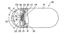
図2(A)に示すようにカプセル型内視鏡3は、円筒形状でその後端を丸くして閉塞した外装ケース16の先端側となる開口する端部に半球面形状の透明カバー17を水密的に接続固定してその内側を密閉し、その密閉したカプセル状容器内に以下の内蔵物を収納している。
【0039】
透明カバー17に対向する中央部には、基板21の中央部の筒部とこの筒部に嵌合するレンズ枠22に取り付けた対物光学系23が配置され、その結像位置には固体撮像素子として例えばCMOSイメージャ24が配置されている。
【0040】
また、対物光学系23の周囲には、例えば図2(B)に示すように4箇所に白色LED25が例えば八角形状の基板21の前面に取り付けられる。このように対物光学系23の周囲の複数箇所に照明手段としての白色LED25を配置することにより、被写体周辺部まで明るい良好な観察画像(撮像画像)が得られるようにしている。
【0041】
さらに、被写体側からカプセル内に配置された対物光学系を正面視したときに、対物光学系の光軸101を中心として白色LED25と対称な領域が、CMOSイメージャ24の撮像面100のうち撮像に使用されないエリアと重なるように白色LED25とCMOSイメージャ24の位置関係を決めつつカプセル内視鏡の小型化を図った。本実施例では、白色LED25と対称な領域にも白色LEDを配置した。
【0042】
なお、白色LED25は間欠的な発光、つまりフラッシュ発光される。また、撮像側もフラッシュ発光に同期した撮像を行う。このようにすることにより、動きがある場合にも、ブレの少ない、かつ低消費電力で良好な観察画像が得られるようにしている。
【0043】
図2(A)に示すように、この八角形状の基板21における筒部に対向する裏面(背面)側部分は例えば正方形状に切り欠かれて凹部が形成され、その凹部周囲の凸面に当接するように位置決めされてCMOSイメージャ24の前面周縁部が固定されている。
【0044】
また、この基板21におけるCMOSイメージャ24の周囲には白色LED25を駆動するLED駆動回路を構成するチップ部品26が実装されている。
CMOSイメージャ24の背面側には、CMOSイメージャ24を駆動すると共に、CMOSイメージャ24から出力される撮像信号に対する信号処理、制御処理を行う駆動処理回路27と、この駆動処理回路27により生成された映像信号を高周波変調して無線送信する信号に変換する無線通信回路28と、LED駆動回路、駆動処理回路27、無線通信回路28に動作電力を供給する内蔵電源としてのボタン型電池29とがカプセル容器の軸方向に積層するようにして配置されている。
【0045】
また、駆動処理回路27と無線通信回路28に隣接する側部には無線通信回路28に接続され、無線で放射するアンテナ30が配置されている。
また、例えば電池29に隣接するカプセル容器の後端部付近の内側には、非接触で作動させる非接触作動スイッチ31と、このカプセル型内視鏡3を磁気力で誘導できるようにするための永久磁石32とが配置されている。
【0046】
非接触作動スイッチ31のON/OFFされる2つの接点は電池29の一方の電極(例えば正極)と、電源が供給される回路との間に接続されている。そして、カプセル容器の外部から所定の方向性を持った磁気を作用させることにより、2つの接点をOFFからONさせることができるようにしている。なお、ONになると、さらに内部のアナログスイッチをONにして、磁気を取り去ってもアナログスイッチによるON状態を維持するようにしている。
【0047】
このため、永久磁石32に磁気力を印加してカプセル型内視鏡3を誘導したりする場合においても、カプセル型内視鏡3は動作状態を維持できるようにしている。
【0048】
本実施の形態におけるカプセル型内視鏡3においては、図2(A)に示すように透明カバー17を半球形状にすると共に、その内側に配置される対物光学系23はその入射瞳34が透明カバー17の曲率の中心位置に位置するようにして収納固定されている。
【0049】
より具体的には、透明カバー17はその内面と外面の曲率半径RiとRoとが同じ中心位置から、例えば5mmと5.5mmとで均一な肉厚で形成されている。つまり、透明カバー17を肉厚が均一な半球形状とすることにより、容易に加工できる形状にしている。
【0050】
そして、この同じ中心位置に対物光学系23の入射瞳34が位置するように、対物光学系23をカプセル容器内に配置し、この対物光学系23が配置された中心付近から離間した周囲の位置に照明手段としての白色LED25を配置している。
【0051】
また、透明カバー17の内面には、透明な誘電体等による反射防止コート35が施されており、照明手段による不要な光が反射するのを有効に防止(低減)し、良好な観察画像が得られるようにしている。
【0052】
また、レンズ枠22等で反射された不要な光が対物光学系23に入射しないように、レンズ枠22の前面の円錐面状部分や白色LED25を取り付けた基板21の前面部分等には黒色の塗料を塗布等したコーディング膜36を形成する等して反射防止手段(光吸収手段)を設けている。なお、反射防止或いは吸収(減衰)させるコーディング膜36の他に、灰色、深緑色等の暗い色、ぎざぎざ状、つや消し、羽毛又はビロード等の表面性状にして、反射防止或いは吸収(減衰)等と同様の機能を持たせるようにしても良い。
【0053】
なお、本実施の形態では、この対物光学系23による結像可能となる視野範囲の角度θは例えば110度程度に設定され、レンズ枠22の前端側は円錐面状に切り欠かれてこの視野範囲の角度θからの入射光は対物光学系23に入射できるようにしている。
【0054】
このような構成にすることにより、照明手段による照明光が透明カバー17の内面で反射した場合にも、その反射光が対物光学系23に入射しにくいようにしている。
【0055】
図3は対物光学系23部分を拡大して示す。この対物光学系23は被写体側に配置される、例えば平凸レンズからなる第1レンズ37と、この第1レンズ37の光軸上で後方側に配置される、例えば凸平レンズからなる第2レンズ38とからなり、第1レンズ37の前面の光軸上の入射瞳位置34の周囲は遮光性の薄板或いは黒色塗料等で遮光されて明るさ絞り39が形成されている。
【0056】
第2レンズ38の後方位置には、その光軸上の位置が撮像手段(具体的にはCMOSイメージャ24)の撮像面100の中心に一致するようにして配置されている。
【0057】
そして、入射瞳位置34に向かって入射される光線は明るさ絞り39で光束が制限され、図3に示すようにCMOSイメージャ24の撮像面100に結像するように設定されている。
【0058】
次に本実施の形態の作用を説明する。
図示しない永久磁石をカプセル型内視鏡3の後端側の非接触作動スイッチ31に、所定の着磁方向から近づけることにより、公知のリードスイッチを用いて形成した非接触作動スイッチ31がONされ、電池29から駆動処理回路27等の各回路には動作に必要な電力が供給される。
【0059】
つまりカプセル型内視鏡3は動作状態になる。すると、以下により詳しく説明するようにカプセル型内視鏡3は画像信号をアンテナ30から無線で放射し、体外ユニット5はそれを受けて復調し、液晶モニタ13に表示する。従って、液晶モニタ13にカプセル型内視鏡3により撮像した画像が表示されることを確認して、術者は患者2がこのカプセル型内視鏡3を飲み込むように指示する。
【0060】
このカプセル型内視鏡3を飲み込むことにより、カプセル型内視鏡3は食道、胃等を通過する。カプセル型内視鏡3は動作状態になると、カプセル型内視鏡3の内部の駆動処理回路27の制御部は基板21により形成されるLED駆動回路に制御信号を送り、LED駆動回路は所定の間隔で白色LED25をフラッシュ発光させる。
【0061】
白色LED25によるフラッシュ発光された光は、その前方の透明カバー17を透過して、その外部を照明する。照明された透明カバー17の外部の食道管部等の被写体は対物光学系23により、その結像位置に配置されたCMOSイメージャ24の撮像面に像を結び、光電変換される。
【0062】
上記フラッシュ発光に同期して(例えば、フラッシュ発光の終了時に)、駆動処理回路27はCMOSイメージャ24に駆動信号を送り、光電変換された撮像信号を出力させ、駆動処理回路27によりその信号成分を抽出する映像信号(画像信号)生成処理を行う。
【0063】
生成された映像信号は無線通信回路28(の送信部)に送られ、変調された後、アンテナ30から電波として放射される。この電波は患者2の体外に設けたアンテナユニット4を介して体外ユニット5の内部(の無線通信回路の受信部)で受信され復調された後、さらにA/D変換等されてハードディスクに蓄積されると共に、表示回路を経て液晶モニタ13によりCMOSイメージャ24で撮像された画像が表示される。
【0064】
そして、例えば主要な検査部位、例えば小腸付近に達した場合、或いは小腸付近に達すると予想される時間等において、体外ユニット5の操作ボタン14を操作して、より短い時間間隔で撮像する指示操作を行うと、その指示信号が体外ユニット5からカプセル型内視鏡3に電波で送信される。
【0065】
カプセル型内視鏡3はその電波を無線通信回路28(の受信部)に送り、復調され、その復調された信号はさらに駆動制御回路27の制御部に送られ、指示信号の内容が判断され、その判断結果により、フラッシュ発光する時間間隔を短くすると共に、それに連動してCMOSイメージャ24を駆動する時間間隔を短くする。
【0066】
この場合には、より短い間隔で撮像された画像データが体外ユニット5のハードディスクに蓄積されるようになる。
このようにして被写体を照明及び撮像する場合、対物光学系23の入射瞳位置34は透明カバー17の半球面の曲率半径の中心位置、より具体的には球心位置に設定されており、照明手段(発光素子)としての白色LED25は球心位置から離間した位置に配置されているので、照明手段による照明光は仮に透明カバー17の内面で反射されたとしても、殆ど対物光学系23には入射することがない。
【0067】
この作用を図4(A)、図4(B)を参照して説明する。
図4(A)は透明カバー17の内面における任意の位置P0で反射された光線は、位置P0の接平面に対して垂直に反射する場合のみ、球心に戻ることを示している。
【0068】
つまり、球心の位置に光の射出点、つまり白色LED25が設定された場合に、反射光は球心の位置に戻る。
図4(B)は球心の位置と光の射出点、とが一致しない場合の図を示す。
【0069】
この場合には、射出点、からの光線が、透明カバー17の内面の任意の点P1或いはP2で反射された場合、この図に示すように接平面と垂直な線(この線は点線で示すように球心を通る)と成す角φ1、φ2の2倍の角度で反射するので、球心に戻る(入射する)ことは無い。
【0070】
このように図4(A)、(B)より、発光素子としての白色LED25を透明カバー17の球心以外の位置に配置しているので、透明カバー17で反射された光線が球心の位置、つまり対物光学系23の入射瞳位置34に入射することを防止できる。
【0071】
従って、透明カバー17の内面などで反射された光が対物光学系23に入射することにより発生するフレヤやゴーストを有効に防止することができる。
また、被写体側からカプセル内に配置された対物光学系を正面視したときに、対物光学系の光軸101を中心として白色LED25と対称な領域が、CMOSイメージャ24の撮像面100のうち撮像に使用されないエリアと重なるようにしたことにより、被写体と透明カバー17が密着して、視野周辺から視野外にかけて適正な照度が得られなくなった場合にも、観察画像に影響を与えずに観察を行うことができる。
【0072】
従って、本実施の形態によれば、良好な観察画像が得られる。
本実施の形態は、固体撮像素子(イメージセンサ)としてCMOSイメージャについて説明したが、固体撮像素子はこれに限定されず、CCDはもちろんのこと、以下の3種類の最新型素子を用いてもよいのは当然である。これらは各々以下に示すような優れたメリットを有している。
【0073】
1つ目は、前記CCDやCMOSイメージャの両方のメリットを兼ね備えた、次世代イメージセンサである「閾値変調型イメージセンサ(VMIS)」である。このセンサは、受光部が3〜5個のトランジスタおよびフォトダイオードで構成されている従来のCMOSセンサとは構造が全く異なり、受光による発生電荷でMOSトランジスタの閾値を変調させて、この閾値の変化を画像信号として出力させる技術を使った構造のイメージセンサである。
【0074】
このイメージセンサの特徴はCCDの高画質と、CMOSセンサの高集積化や低電圧駆動、低消費電力を両立した点である。
このため、使い捨て型のカプセル内視鏡に適している。この特徴を活かすことで、使い捨て型内視鏡(軟性鏡または硬性鏡)や安値内視鏡を実現できるので、これらの内視鏡はもちろん通常のビデオスコープにこのイメージセンサ(VMIS)を使うことができるのは当然である。
【0075】
この他に以下のような優れた特徴も有している。
・イメージセンサー1個につきトランジスタ1個のシンプルな構造。
・高感度と高ダイナミックレンジなど優れた光電特性を有する。
・CMOSプロセスでの製造が可能なため、高密度化と低価格化を実現可能。
【0076】
センサのタイプとしては、QCIF(QSIF)サイズ、CIF(SIF)サイズ、VGAタイプ、SVGAタイプ、XGAタイプなど各種あるが、本発明(本実施の形態及び他の実施の形態を含む)のような無線通信タイプのカプセル型内視鏡には、飲みやすさと無線電送速度・消費電力の点で「QCIF(QSIF)サイズ」、「CIF(SIF)サイズ」の小さなものが特に適している。
【0077】
2つ目は、前記CMOSイメージャに画像処理用の回路をワンチップ化したシステムLSIである、いわゆる「人工網膜LSI」である。このチップは、画像の検出とその画像の特徴を抽出する処理を同時に行っており、人間の網膜と同様の機能を持っている。通常のCCDやCMOSイメージセンサーは画像の検出だけで特徴処理、認証処理を外部の画像処理プロセッサで行っているが、人工網膜チップはチップ上でそれを行うため、回路を簡素化、小型化できる。また、高速処理可能、単一電源で駆動可能、低消費電力駆動可能などのメリットがある。
【0078】
このため、使い捨て型のカプセル内視鏡に適している。この特徴を活かすことで、使い捨て型内視鏡(軟性鏡または硬性鏡)や安値内視鏡を実現できるので、これらの内視鏡はもちろん通常のビデオスコープにこのイメージセンサ(人工網膜チップ)を使うことができるのは当然である。
【0079】
この他に以下のような優れた特徴も有している。
・画像の輪郭抽出、ホワイトバランス、エッジ強調、彩度調整、ガンマ補正機能内臓、A/D変換機能内蔵
・高感度、高画質
・小サイズパッケージ
・ノイズ低減回路(相関二重サンプリング)内蔵可能
センサのタイプとしては、QCIF(QSIF)サイズ、160×144サイズ、CIF(SIF)サイズ、VGAタイプ、SVGAタイプ、XGAタイプなど各種考えられるが、本発明のような無線通信タイプのカプセル型内視鏡には、飲みやすさと無線電送速度・消費電力の点で「QCIF(QSIF)サイズ」、「160×144サイズ」、「CIF(SIF)サイズ」の小さなものが特に適している。
【0080】
3つ目は、同画素数で従来型イメージセンサの2倍の解像度を実現することができる、シリコン内に3つのフォトディテクター(受光層)を奥行き(縦)方向に配置し、シリコン内で光の波長により吸収される層が異なることを利用し、1画素でRGBの各色信号を得るカラーイメージセンサである。3CCDや3ショットカメラの長所を通常の単板センサで実現したものである。
【0081】
特にこの技術をCMOSイメージセンサで実施することで、従来型並に安価に作れるという優れたメリットがある。
前記カラーイメージセンサの各色信号の読み出し方式は、数画素のデータをまとめて読み出すVPS(Variable Pixel Size)方式である。これにより、ピクセルサイズの変更が可能になるというメリットがある。また、静止画像撮影時の高感度化や、ビデオ撮影(動画撮影)に必要な高速読み出しが実現可能というメリットもある。
【0082】
また、構造上、偽色が発生しないため、ローパスフィルターを省いて使用可能であり、本方式のカラーイメージセンサは、小型・省電力が必要なカプセル型医療装置に適している。また、通常型のビデオスコープにも適している。
【0083】
また、本実施の形態は、Bluetooth規格準拠の無線技術を使っているが、これに限定されず、現在開発中の広帯域を利用するパルスを使った無線技術を用いてもよく、これを利用することによって以下のような優れたメリットが出せる。
・電波を広帯域に拡散することができ、その電波出力が雑音レベルに近くなる。
【0084】
したがって従来の狭帯域通信と併用が可能となる。
加えて狭帯域通信のようにキャリア周波数を持たないため信号を直接解析することが可能であり、例えば到達時間を測ることにより距離情報が精度よく取り出しやすい特徴がある。
【0085】
精度の良い距離情報があれば位置情報に関しても精度が良くなることになる。最近ではパルス無線の代表的なものとしてUWB(Ultra Wideband)技術が発表され、製品化されている。
【0086】
これをカプセル型医療装置の無線通信装置に組み込むと、例えば人体を透過しやすい波長の長い周波数を使うことができる。人体の透過率が高くなれば必要な出力電力をよりいっそう下げることができ、ひいては無線通信装置の消費電力を抑えることが可能となる。
【0087】
また精度の良い位置情報を得ることが可能になる。
(第2の実施の形態)
次に図5を参照して本発明の第2の実施の形態を説明する。図5は第2の実施の形態のカプセル型内視鏡3Bを示す構成図である。
【0088】
このカプセル型内視鏡3Bは、図2のカプセル型内視鏡3における肉厚が均一な透明カバー17の代わりに、中央側の肉厚を大きくした透明カバー17Bを採用している。
【0089】
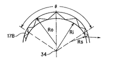
この場合、透明カバー17Bにおける視野範囲内の内面の曲率半径Riは例えば5.5mmで、その曲率半径Riの中心位置が対物光学系23の入射瞳位置34に一致するようにしている。
【0090】
また、透明カバー17Bにおける視野範囲の角度θ内の外面の曲率半径Roは、例えば5.5mmであり、その曲率半径Riの中心位置は対物光学系23の入射瞳位置34より光軸上で前方(この場合には0.5mm)の位置となっている。
【0091】
また、本実施の形態では透明カバー17Bにおける視野範囲の境界部分より外側(周辺側)は、例えばその一方の面、具体的には内面側を、曲率半径Ri(=Ro)からそれより小さい、例えば3mmの曲率半径Rsに繋げて、均一な肉厚にしてから外装カバー16の前端で嵌合させて接着し、内部を水密構造にしている。この場合には、他方の外面側は曲率半径Roとなっている。
【0092】
なお、本実施の形態では、CMOSイメージャ24の前面はカバーガラス41で覆うようにしている。本実施の形態では、透明カバー17Bにおける中央側程その肉厚を大きくして、透明カバー17Bが破損することを有効に防止できる強度に設定している。
【0093】
また、本実施の形態では、第1の実施の形態で説明したように透明カバー17Bの内面で反射された光は入射瞳位置34以外の所に向かうので、視野範囲の角度θ内には殆ど入らない。
【0094】
また、透明カバー17Bの中央側を周辺側に対して滑らかにその肉厚が大きくなるように繋げることで、透明カバー17B内の反射光が透明カバーの中を通って周辺位置から抜けるようにすることで、さらに不要光が撮像手段に入りにくくし、良好な観察画像を得ることができるようにしている。
【0095】
この様子を図6を参照して説明する。
光源等から出射して透明カバー17Bの内面を通過し、透明カバー17Bの外面で反射した一部の照明光は、再び透明カバー17Bの内面に入射する。このとき、透明カバー17Bの持つ屈折率と空気層の屈折率の関係によって決まる全反射角を満たす角度で入射する前記外面からの反射光は、前記透明カバー17Bの内面で全反射して更に再び前記透明カバー17Bの外面へ入射する。
【0096】
透明カバー17Bに反射防止膜などのコーティングが施されている場合には、厳密にはコーティング面の屈折率を考慮する必要があるが、ここでは簡単のため省略する。
【0097】
このように、透明カバー17Bの外面からの反射光が、前記透明カバー17Bの内面と外面で全反射を繰り返えす。図6に示すように全反射を繰り返えした場合の反射角は周辺部側ほど小さくなるので、周辺部側で透明カバー17Bから外部に抜けるようになる。
【0098】
従って、照明光が透明カバー17Bの外面で反射されて、その透明カバー17Bの外面及び内面で多重反射するような場合でも、その光が対物光学系23に入射するのを有効に防止ないしは軽減できる。
【0099】
なお、対物光学系23の視野範囲の外側で透明カバー17B内部から空気層へ抜けるように、透明カバー17Bの外面と内面の曲率や、その屈折率を設定すれば、前記透明カバー17Bの外面からの反射光が視野内フレアとして観察に悪影響を及ぼす事を防止できる。
【0100】
このとき、対物光学系は視野内でカバーガラスの厚みが変化することを考慮して結像面での光学的な諸収差の補正をしているので、このような形状のカバーガラスを用いても良好な観察画像が得られることはいうまでもない。
【0101】
従って本実施の形態は以下の効果を有する。
本実施の形態によれば、透明カバー17Bの内面の曲率中心と入射瞳位置34とが殆ど一致しているので、透明カバー17Bの内面による反射光が対物光学系23に入射するのを有効に防止できる。
【0102】
また、透明カバー17Bの外側の面で反射した光も、視野範囲の外側部分で抜け易くしているので、やはり対物光学系23に入射される不要光を軽減することができる。また、落下させるような衝撃が加えられても透明カバー17Bが破損するのを有効に防止できる。
【0103】
図7は第1変形例のカプセル型内視鏡3Cの構成図である。このカプセル型内視鏡3Cでは、透明カバー17Cはその内面の曲率半径Riが視野範囲の周辺付近までは、例えば6mmに設定され、その曲率の中心位置に対物光学系23の入射瞳位置34が一致するように設定され、また、外面の曲率半径Roが視野範囲の周辺付近までは、例えば5.5mmに設定され、その中心位置は入射瞳位置34より前方に設定されている。
【0104】
また、図5の場合と同様に、透明カバー17Cにおける視野範囲の境界付近より外側(周辺側)は、例えばその内面側を、曲率半径Ri(=Ro)からそれより小さい、例えば3mmの曲率半径Rsに繋げて、均一な肉厚にしてから外装カバー16の前端で嵌合させて接着し、内部を水密構造にしている。
【0105】
この第1変形例によれば、白色LED25による照明光が透明カバー17C内面で反射されても対物光学系23に入射されるのを有効に防止できる。また、透明カバー17Cの中央側の肉厚を大きくしているので、破損するのを有効に防止できる。
【0106】
図8及び図9は第2及び第3変形例のカプセル型内視鏡3D及び3Eの構成図である。このカプセル型内視鏡3D、3Eでは、透明カバー17D、17Eの外面の曲率半径Ro(具体的には]RO=5.5mm)の中心位置が入射瞳位置34になるように設定し、内面の曲率半径Riの中心位置は入射瞳位置34よりも光軸上で後方位置に設定している。
【0107】
具体的には、透明カバー17Dの内面の曲率半径Riは5.5mmに設定され、透明カバー17Eの内面の曲率半径Riは6.0mmに設定されている。
第2及び第3変形例では、白色LED25からの照明光が透明カバー17D或いは17Eの内面で反射するのを有効に反射防止コート35で防止している。また、外面で反射した場合には、対物光学系23には入射しないようにできる。
(第3の実施の形態)
図10(A)は本発明の第3の実施の形態のカプセル型内視鏡51の断面図である。図10(B)は被写体側からカプセル内に配置された対物光学系を正面視したときに、撮像手段と照明手段の位置関係を示した図である。このカプセル型内視鏡51は筒状でその先端側をほぼ半球形状にした透明な前カバー52と、筒形状でその後端をほぼ半球形状にした後カバー53との後端及び前端を嵌合させてその内部に水密構造のカプセル容器を形成し、その内部に対物光学系54等を収納している。
【0108】
前カバー52に対向する中央位置には、第1レンズ枠55と第2レンズ枠56とにそれぞれ第1レンズと第2レンズを取り付けて形成した対物光学系54が配置され、その結像位置には基板57の前面に取り付けたCMOSイメージャ58が配置されている。
【0109】
また第2レンズ枠56に嵌合するようにして固定された基板59には白色LED60が取り付けられている。
図10(B)に示されるように、白色LED60は対物光学系の光軸101を中心にしてリング状に配置されており、CMOSイメージャ58の撮像面100の撮像に使用されないエリアと重なっている。
【0110】
CMOSイメージャ58を取り付けた基板57は接続部61で駆動処理回路62を形成し、電気部品が実装された基板に電気的に接続されている。また、この駆動処理回路62を形成する基板の背面にはメモリ等を実装した記憶回路63を構成する基板が接続部64で接続するようにして配置されている。
【0111】
この記憶回路63を構成する基板の背面には無線通信回路65を構成する基板が接続部66で接続するようにして配置されている。
さらにこの無線通信回路65を構成する基板の背面にはボタン型の2つの電池67が配置されている。
【0112】
また、駆動処理回路62を形成する基板に隣接してアンテナ68が配置されている。
また、電池67は、例えばその負極が無線通信回路65等のグランドに接続され、無線通信回路65等の(負の)電源端には図示しないリードで接続されている。また、無線通信回路65等の(正の)電源端はバネ状接点部材71のリード部の一端と接続されている。
【0113】
このバネ状接点部材71は電池67の背面部分で一方の接点部71aとなり、この接点部71aに近接するようにして電池67の正極に接続された他方の接点部71bとの間に絶縁性の板73が介挿されて、OFFの状態に設定されている。
【0114】
この絶縁性の板73の一部は後カバー53に設けた弁部(或いはゴム栓部)74の小さな切り欠きを通して外部に露出し、この絶縁性の板73を引き抜くことにより接点部71a、71bは接触してONとなる。また、弁部74は閉じて水密を保持する(この様子は図11(A)、(B)で示している)。
【0115】
前カバー52における前端のドーム形状部分の内面及び外面は、その視野範囲の周辺付近までは一定の曲率半径Ri及びRoに設定されている。本実施の形態では、例えばRi=6.0mm及びRo=6.5mmに設定されている。
【0116】
また、曲率半径Ri及びRoの中心位置が対物光学系54の入射瞳75の位置となるように設定されている。なお、本実施の形態では前カバー52の肉厚は均一にしている。
【0117】
また、視野範囲の周辺付近では、例えば外面の曲率半径Rpを曲率半径Ri及びRoより小さい値(具体的にはRs=4.0mm)に設定してその外径部分側と滑らかに繋ぐようにしている。なお、本実施の形態ではこのカプセル型内視鏡51の外径Dを11mmに設定している。
【0118】
また、第1のレンズ枠55の円錐形状の前面はその表面を粗面76等にすることにより反射防止する機能を持たせている。
本実施の形態においても、第1の実施の形態と同様に、照明光が前カバー52の内面や外面で反射しても、その反射光が対物光学系54に入射するのを有効に防止できる。つまり、不要な光が対物光学系54に入射するのを有効に防止でき、良好な画像を得ることができる。
【0119】
また、被写体側からカプセル内に配置された対物光学系を正面視したときに、対物光学系の光軸101を中心として白色LED60が、CMOSイメージャ58の撮像面100のうち撮像に使用されないエリアと重なるようにしたことにより、被写体と前カバー52が密着して、視野周辺から視野外にかけて適正な照度が得られなくなった場合にも、観察画像に影響を与えずに観察を行うことができる。
(第4の実施の形態)
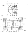
図11(A)は本発明の第3の実施の形態のカプセル型内視鏡81の断面図である。なお、図11(B)には板を引き抜いてONにした状態が示されている。図11(C)は被写体側からカプセル内に配置された対物光学系を正面視したときに、撮像手段と照明手段の位置関係を示した図である。図11(D)は第4実施例の変形例において被写体側からカプセル内に配置された対物光学系を正面視したときに、撮像手段と照明手段の位置関係を示した図である。
【0120】
このカプセル型内視鏡81は筒状でその後端を丸くして閉塞した外装カバー82の前端に略半球形状の透明カバー83を嵌合させて接着等して、その内部を水密構造にし、対物光学系84等を収納している。
【0121】
透明カバー83に対向する中央位置には、第1レンズ枠85と第2レンズ枠86とにそれぞれ第1レンズと第2レンズを取り付けて形成した対物光学系84が配置され、その結像位置には基板87の前面に設けた凹部の平面部にCCD88が配置されている。
【0122】
また第1レンズ枠85に嵌合する第2レンズ枠86の筒部に固定される基板90には白色LED91が取り付けられている。
図11(C)に示されるように、白色LED91は対物光学系の光軸101を中心にして白色LED91と対称な領域(図中斜線部)がCCD88のオプティカルブラック部に重なるように配置されている。オプティカルブラック部は、撮像面100の画素上に遮光マスクが施されたエリアであって、撮像には使用されないエリアである。
【0123】
また、別の種類のCCD88’を使用した場合、図11(D)のように白色LED91を配置することが可能である。CCD88’には、オプティカルブラック部と信号読み出し部があり、これらの部分は撮像には使用されない。そこで、白色LED91は対物光学系の光軸101を中心にして白色LED91と対称な領域(図中斜線部)が上記の撮像に使用されない部分と重なるように配置されている。なお図中では説明のために、白色LED91と対称な領域を斜線で示したが、実際には斜線領域にも白色LED91が配置されている。
【0124】
CCD88を取り付けた基板87の背面には電気部品を実装した駆動処理&記憶回路92を形成する基板が配置され、さらにその背面には無線通信回路93を構成する基板が配置されている。この基板の両面にはチップ部品94等が実装されている。
【0125】
この無線通信回路93を構成する基板の背面側にはボタン型の電池67が配置されている。
また、駆動処理回路62を形成する基板に隣接する側部にはアンテナ95が配置されている。
【0126】
また、電池67は、図10で説明した場合と同様にバネ状接点部材71と接続され、その接点部71aと対向する接点部71bとの間に絶縁性の板73が介挿されて、OFFの状態に設定され、図11(B)に示すように絶縁性の板73を引き抜くことにより接点部71a、71bは接触してONとなる。
【0127】
本実施の形態では透明カバー83のドーム形状部分の内面及び外面は、その視野範囲内では一定の曲率半径Ri及びRoに設定されている。本実施の形態では、例えばRi=4.5mm及びRo=5.0mmに設定されている。
【0128】
また、曲率半径Ri及びRoの中心位置が対物光学系84の入射瞳位置96となるように設定されている。なお、本実施の形態では透明カバー83の肉厚は均一にしている。
【0129】
また、透明カバー83は、視野範囲の境界付近から平面に近い形状で周辺側に延出され、外径部分に近い付近ではその外面の曲率半径Rpを曲率半径Riより小さい値(具体的にはRp=3.0mm)に設定してその外径部分側と滑らかに繋ぐようにしている。なお、本実施の形態ではこのカプセル型内視鏡81の外径Dは11mmに設定している。
【0130】
なお、本実施の形態では、第1のレンズ枠85は筒形状であり、その第1のレンズ枠85に取り付けた第いレンズの前面は入射瞳位置96の周囲を遮光性の薄板或いは塗料で遮光して明るさ絞り97を形成している。
【0131】
本実施の形態では、カプセル型内視鏡81の外径Dに対して、その前面側での曲率半径を外径Dの半径よりも小さくしているので、その全長を短くすることができる。
【0132】
本実施の形態のその他の作用効果は第1の実施の形態とほぼ同様である。
なお、例えば図2(A)において、外装ケース16内に対物光学系23を含む内蔵物を収納し、透明カバー17の後端部分を外装ケース16の先端部分に嵌合させて接着剤で密閉固定する場合、その密閉固定前に嵌合する部分を前後に調整することにより、対物光学系23の入射瞳位置34が透明カバー17の曲率半径Ri、Roの中心位置となるように調整した後、接着剤で固定するようにしても良い。
【0133】
つまり、透明カバー17と外装ケース16との嵌合部分で対物光学系23の入射瞳位置34が透明カバー17の曲率半径Ri、Roの中心位置に位置合わせする手段に利用しても良い。このようにして位置合わせする手段を設けることにより、対物光学系23の入射瞳位置34を精度良く透明カバー17の曲率半径Ri、Roの中心位置に位置合わせすることができる。
【0134】
なお、この場合の位置合わせは図示しない光学機器を用いて行っても良いし、実際に照明及び撮像を行ってフレアなどの影響が最も少ない位置に設定するようにしても良い。なお、第1の実施の形態で位置合わせする構造を説明したが、他の実施の形態に利用しても良い。
(第5の実施の形態)
図12(A)は本発明の第5実施例のカプセル型内視鏡の先端部分の断面図である。図12(B)は被写体側からカプセル内に配置された対物光学系を正面視したときに、撮像手段と照明手段の位置関係を示した図である。図12(C)は第5実施例の変形例において被写体側からカプセル内に配置された対物光学系を正面視したときに、撮像手段と照明手段の位置関係を示した図である。
【0135】
なお、以後の実施例では透明カバーと、対物光学系を含んだ撮像手段と、照明手段と、をもって発明の主要な構成をなすので、それ以外の部分は省略して説明する。
【0136】
本実施の形態におけるカプセル型内視鏡は、図12(A)に示すように透明カバー110を半球形状にすると共に、その内側に配置される対物光学系112はその入射瞳が透明カバー110の曲率の中心位置に位置するようにして収納固定されている。対物光学系112の結像面にはCCD113の撮像面100が配置されている。対物光学系112の周囲には白色LED111が取り付けられている。
【0137】
さらに、図12(B)に示すように、被写体側からカプセル内に配置された対物光学系を正面視したときに、対物光学系112を通して撮像面100に擬似的に投影された電気マスク114の外側の領域(図中斜線部)と、対物光学系の光軸101を中心として白色LED111と対称な領域が重なるように白色LE111とCCD113の位置関係を決めつつカプセル型内視鏡の小型化が図られている。本実施例では、白色LED111と対称な領域にも白色LEDを配置した。上記電気マスク114は円形であって、対物光学系112の歪曲収差が補正されているために撮像面100には円形のまま投影されている。電気マスク114の外側の領域(図中斜線部)は撮像に使用されるエリアであるが、画像処理の時点で電気的にマスクされるため、このエリアに結像した被写体の像は画像化されない。
【0138】
また、第5実施例の変形例を、図12(C)に示した。第5実施例の変形例において、電気マスク114は8角形状であり、対物光学系112が負の歪曲収差を発生させているために撮像面100には対物光学系の光軸101の方向に歪んだ8角形が投影されている。白色LED111は、対物光学系の光軸101を中心として対称な領域が電気マスク114の外側の領域(図中斜線部)と重なるように、CCD113の対角方向に4箇所配置されている。
【0139】
上記のような構成とすることで、被写体と透明カバー17が密着して、視野周辺から視野外にかけて適正な照度が得られなくなった場合にも、観察画像に影響を与えずに観察を行うことができる小型のカプセル型内視鏡を提供することができる。
(第6の実施の形態)
また、上述の説明では、対物光学系(第5の実施の形態では112)は単眼撮像を行う例であったが、視差を有する立体撮像を行う左右の対物光学系等を備えたカプセル型内視鏡に適用する場合には、透明カバーの曲率半径の中心位置に照明手段の射出瞳を配置し、その周囲に複数の対物光学系を配置しても良い。
【0140】
図13(A)は複数の対物光学系を備えたカプセル型内視鏡の主要部の構成を示した断面図である。図13(B)は被写体側からカプセル内に配置された対物光学系を正面視したときに、撮像手段と照明手段の位置関係を示した図である。本実施の形態におけるカプセル型内視鏡は、図13(A)に示すように透明カバー120を半球形状にすると共に、白色LED122の前方に配置される光拡散手段123の射出瞳が透明カバー120の曲率の中心位置に位置するようにして収納固定されている。白色LED122の周りには対物光学系125、126が配置され、それぞれの結像面にはCCD127、128の撮像面100、100’が配置されている。また、光拡散手段123の中心軸117を含んで、図面と垂直な面内に中心軸をもった、図示されない白色LED129a、129bが上記中心軸117と平行に配置されている。
【0141】
また、図13(B)に示すように、被写体側からカプセル内に配置された対物光学系を正面視したときに、対物光学系125を通して撮像面100に擬似的に投影された電気マスク130の外側の領域と、対物光学系の光軸118、を中心として白色LED129a、129bと対称な領域131a、131bが重なるように配置されている。同様に、対物光学系126を通して撮像面100’に擬似的に投影された電気マスク130’の外側の領域と、対物光学系の光軸119、を中心として白色LED129a、129bと対称な領域131a’、131b’が重なるように配置されている。
【0142】
このように構成することで、複数の撮像手段を備えたカプセル型内視鏡においても、被写体と透明カバー120が密着して、視野周辺から視野外にかけて適正な照度が得られなくなった場合に、観察画像に影響を与えずに観察を行うことができる。
(第7の実施の形態)
図14(A)は複数の対物光学系を備えた別のカプセル型内視鏡の主要部の構成を示した断面図である。図14(B)は被写体側からカプセル内に配置された対物光学系を正面視したときに、撮像手段と照明手段の位置関係を示した図である。本実施の形態におけるカプセル型内視鏡は、図14(A)に示すように透明カバー141を半球形状にすると共に、白色LED142の前方に配置される光拡散手段143の射出瞳が透明カバー141の曲率の中心位置に位置するようにして収納固定されている。
【0143】
白色LED142の周りには対物光学系144、145が配置され、それぞれの結像面には共通のCCD146の撮像面100が配置されている。また、光拡散手段143の中心軸140を含んで、図面と垂直な面内に中心軸をもった、図示されない白色LED149a、149bが上記中心軸140と平行に配置されている。
【0144】
また、図14(B)に示すように、被写体側からカプセル内に配置された対物光学系を正面視したときに、対物光学系144を通して撮像面100に擬似的に投影された電気マスク150の外側の領域かつ対物光学系145を通して撮像面100に擬似的に投影された電気マスク150’の外側の領域と対物光学系の光軸147を中心として白色LED149a、149bと対称な領域151a、151bが重なるように配置されている。同様に、対物光学系144を通して撮像面100に擬似的に投影された電気マスク150の外側の領域かつ対物光学系145を通して撮像面100に擬似的に投影された電気マスク150’の外側の領域と対物光学系の光軸148を中心として白色LED149a、149bと対称な領域151a’、151b’が重なるように配置されている。
【0145】
このように構成することで、複数の撮像手段を備えたカプセル型内視鏡においても、被写体と透明カバー141が密着して、視野周辺から視野外にかけて適正な照度が得られなくなった場合に、観察画像に影響を与えずに観察を行うことができる。
【0146】
なお上述した各実施の形態を部分的に組み合わせて構成される実施の形態も本発明に属する。
また、すべての実施例において、前記透明カバーの内面に反射防止コーティングを施すことは、視野内に直接入射する観察に不要な光を減少させる以外に、視野外から該透明カバーの内面を経由して間接的に対物光学系に入射する観察に不要な光をも減少させる利点をもっている。
【0147】
また、すべての実施例において、前記透明カバーの外面に撥水性のコーティングを施すことで、観察中に該透明カバーの外面に異物が付着して観察の妨げになるのを防ぐことができる。
【0148】
また、すべての実施例において、前記透明カバーと対物レンズの光学材料として、鉛や砒素など環境に対して有害な成分を含まないものを使用すべきであることは言うまでもない。これらの素材は人体に対しても安全であって、しかも廃棄処分コストを低減することができる。
【0149】
【発明の効果】
以上説明したように、本発明によれば、照明手段による照明光が透明カバーで反射されたような場合には、その不要な光が対物光学系に入射されるのを有効に防止でき、さらに被写体と透明カバーが密着して、視野周辺から視野外にかけて適正な照度が得られなくなった場合にも、観察画像に影響を与えずに観察を行うことができる。
【図面の簡単な説明】
【図1】 本発明の第1の実施の形態を備えたカプセル型内視鏡装置等の構成を示す図。
【図2】 カプセル型内視鏡の内部構成及び正面側から見た基板など示す図。
【図3】 対物光学系の構成を拡大して示す図。
【図4】 対物光学系の瞳位置を透明カバーの半球状内面の球心位置に設定し、その位置以外に照明手段を配置した場合の作用説明図。
【図5】 本発明の第2の実施の形態のカプセル型内視鏡の構成を示す断面図。
【図6】 透明カバーによる作用の説明図。
【図7】 第1変形例のカプセル型内視鏡の構成を示す断面図。
【図8】 第2変形例のカプセル型内視鏡の構成を示す断面図。
【図9】 第3変形例のカプセル型内視鏡の構成を示す断面図。
【図10】 本発明の第3の実施の形態のカプセル型内視鏡の構成を示す断面図。
【図11】 本発明の第4の実施の形態のカプセル型内視鏡の構成を示す断面図。
【図12】 本発明の第5の実施の形態のカプセル型内視鏡の構成を示す断面図。
【図13】 本発明の第6の実施の形態のカプセル型内視鏡の構成を示す断面図。
【図14】 本発明の第7の実施の形態のカプセル型内視鏡の構成を示す断面図。
【図15】 体内の管腔状部分を移動しながら観察を行っているときのカプセル型内視鏡の状態を示す断面図。
【図16】 LEDの配光特性を示す図。
【符号の説明】
1 カプセル型内視鏡装置
2 患者
3 カプセル型内視鏡
4 アンテナユニット
5 体外ユニット
6 表示システム
7 パソコン
8 USBケーブル
11 シールドシャツ
12 アンテナ
13 液晶モニタ
16 外装ケース
17 透明カバー
21 基板
22 レンズ枠
23 対物光学系
24 CMOSイメージャ
25 白色LED
27 駆動処理回路
28 無線通信回路
29 電池
30 アンテナ
31 非接触作動スイッチ
32 永久磁石
34 入射瞳
35 反射防止コート
36 コーティング膜
37 第1レンズ
38 第2レンズ
39 明るさ絞り[0001]
BACKGROUND OF THE INVENTION
The present invention relates to a swallowable capsule endoscope that inspects a living body.
[0002]
[Prior art]
In recent years, endoscopes have been widely adopted in the medical field and the industrial field. In recent years, the medical field has been able to reduce the pain of insertion due to insertion by a patient swallowing a capsule-type capsule endoscope without the need for an insertion part in an endoscope. The situation is now in use.
[0003]
In the conventional example, the objective lens and the illumination means by the light emitting diode provided symmetrically so as to sandwich the objective lens are incorporated inside the substantially hemispherical transparent cover, and the object illuminated by the light emitting diode has a portion that becomes the observation range. An image is formed on an image sensor by an objective lens (see, for example, Patent Document 1).
[0004]
In another conventional example, a single optical window is formed so as to form an ellipsoidal dome, and the illumination element and the receiving element include the focal curve of the elliptical dome. Located on or close to the focal curve plane. At this time, since the plurality of illumination elements are arranged on the focal curve, even if the light beam emitted from the illumination element is reflected by the inner surface of the window, it returns to another position on the focal curve. . Therefore, the image receiving element is arranged at a position other than the focal curve to prevent flare and ghosting that adversely affects the image due to the light reflected from the inner surface of the window being incident on the image receiving element (for example, Patent Document 2).
[0005]
The conventional example of
[0006]
Further, in the conventional example of
[0007]
In addition, when the illumination element is a light emitting element such as an LED, the light emitting portion has a certain size. Therefore, in order to arrange the LEDs on the focal curve, the focal curve must be widened to secure a space for arranging the LEDs, and the elliptical dome must be enlarged accordingly. There is a disadvantage that it becomes large.
[0008]
In addition, when the capsule becomes large, the advantage of the capsule endoscope that the pain experienced by the patient during the endoscopic examination can be reduced is not preferable. Therefore, it is necessary to make the capsule as compact as possible by devising the arrangement relationship between the illumination means and the imaging means in the capsule.
[0009]
[Patent Document 1]
JP 2001-91860 A (FIG. 1)
[0010]
[Patent Document 2]
WO 00/76391 A1 (FIG. 1A)
[0011]
[Problems to be solved by the invention]
The present invention has been made in view of the above-described points, and is a small capsule endoscope in which the workability of the transparent cover is good, and unnecessary light from the illumination means is difficult to enter the objective optical system with a simple configuration. The purpose is to provide.
[0012]
[Means for Solving the Problems]
The capsule endoscope of the present invention is
(1) At least illuminating means for illuminating the subject, imaging means for imaging the subject, and the illumination means and the imaging means are covered.A substantially hemispherical transparent cover, at least part of the inner surface being formed as part of a spherical surfaceA capsule endoscope including a transparent cover,
The transparent cover is,Central wall thicknessFrom the peripheral sideFormed large,
The imaging means includes an objective optical system on which a subject image is incident, and an imaging element disposed at an imaging position of the objective optical system,
The objective optical system is a curved surface that constitutes at least part of the inner surface of the transparent cover, and the curvature center of the curved surface that intersects the optical axis extension line of the objective optical systemEntrance pupil position of objective optical systemArranged to match
The illumination means includesFrom the subject sideAboveWhen the objective optical system is viewed from the front, the optical axis of the objective optical system is the center.ConcernedSymmetrical area with illumination meansProjection area of the front view directionIs overlapped with an area that is not used for imaging on the imaging surface of the imaging device.Be placedIt is characterized by that.
(2) At least illuminating means for illuminating the subject, imaging means for imaging the subject, and the illumination means and the imaging means are covered.A transparent cover having a substantially hemispherical shape, wherein at least a part of the outer surface is formed as a part of a spherical surface.A capsule endoscope including a transparent cover,
The transparent cover is,Central wall thicknessFrom the peripheral sideFormed large,
The imaging means includes an objective optical system on which a subject image is incident, and an imaging element disposed at an imaging position of the objective optical system,
The objective optical system is a curved surface that constitutes at least a part of the outer surface of the transparent cover, and the curvature center of the curved surface that intersects the optical axis extension line of the objective optical systemEntrance pupil position of objective optical systemArranged to match
The illumination means includesFrom the subject sideAboveWhen the objective optical system is viewed from the front, the optical axis of the objective optical system is the center.ConcernedSymmetrical area with illumination meansProjection area of the front view directionIs overlapped with an area that is not used for imaging on the imaging surface of the imaging device.Be placedIt is characterized by that.
(3) At least illumination means for illuminating the subject, imaging means for imaging the subject, and the illumination means and the imaging means are covered.A substantially hemispherical transparent cover, at least part of the inner surface being formed as part of a spherical surfaceA capsule endoscope including a transparent cover,
The transparent cover is,Central wall thicknessFrom the peripheral sideFormed large,
The imaging means includes an objective optical system on which a subject image is incident, and an imaging element disposed at an imaging position of the objective optical system,
The objective optical system is a curved surface that constitutes at least part of the inner surface of the transparent cover, and the curvature center of the curved surface that intersects the optical axis extension line of the objective optical systemEntrance pupil position of objective optical systemArranged to match
The illumination means includesFrom the subject sideAboveWhen the objective optical system is viewed from the front, the optical axis of the objective optical system is the center.ConcernedSymmetrical area with illumination meansProjection area of the front view directionIs overlapped with the area of the imaging surface of the imaging device that is not used for imaging.Be placedIt is characterized by that.
(4) At least an illumination unit that illuminates the subject, an imaging unit that captures the subject, and the illumination unit and the imaging unit are covered.A transparent cover having a substantially hemispherical shape, wherein at least a part of the outer surface is formed as a part of a spherical surface.A capsule endoscope including a transparent cover,
The transparent cover is,Central wall thicknessFrom the peripheral sideFormed large,
The imaging means includes an objective optical system on which a subject image is incident, and an imaging element disposed at an imaging position of the objective optical system,
The objective optical system is a curved surface that constitutes at least a part of the outer surface of the transparent cover, and the curvature center of the curved surface that intersects the optical axis extension line of the objective optical systemEntrance pupil position of objective optical systemArranged to match
The illumination means includesFrom the subject sideAboveWhen the objective optical system is viewed from the front, the optical axis of the objective optical system is the center.ConcernedSymmetrical area with illumination meansProjection area of the front view directionIs overlapped with the area of the imaging surface of the imaging device that is not used for imaging.Be placedIt is characterized by that.
(5) The area that is not used for imaging coincides with a mask area that is electrically applied during image processing.
[0013]
As described above, by arranging the illumination means other than the center of curvature of the transparent cover, even when the illumination light from the illumination means is reflected by the transparent cover, the unnecessary light is incident on the objective optical system. Can be effectively prevented.
[0014]
Further, when observing a lumen-like inner wall portion, the inner wall portion to be observed is often located around the visual field. In addition, a transparent cover made of a curved surface is provided in front of the imaging means, and it is assumed that observation is performed in a state where the inner wall portion and the outer surface of the transparent cover are in close contact with each other. As a result, the distance between the luminal inner wall portion and the illuminating means becomes too close to obtain appropriate illuminance, and whiteout occurs from the periphery of the visual field to the region outside the visual field. In order to avoid such a phenomenon that hinders image observation and obtain a good observation image, the present invention has the following configuration.
[0015]
That is, when the capsule is viewed from the front side from the subject side, the illuminating unit and the illuminating unit are arranged such that a region symmetrical to the illuminating unit with the optical axis of the objective optical system as a center overlaps an area of the imaging surface of the imaging device that is not used for imaging The positional relationship of the imaging means was determined.
[0016]
This will be specifically described with reference to FIG. FIG. 15 is a cross-sectional view showing the state of the capsule endoscope when the observation is performed while moving the luminal portion in the body. 80% of the digestive tract, which is the observation route of the capsule endoscope, is an extremely thin lumen, and the following conditions are likely to occur particularly from the small intestine to the large intestine. That is, the tubular
[0017]
An LED is used as the illuminating means, but the illumination light beam emitted from the LED has a range that contributes particularly strongly to the illuminance distribution on the irradiated surface. In general, assuming that the light distribution is substantially Gaussian, about 75% of the light rays are concentrated in a range with an intensity ratio of 0.5 or more. This range is mainly used for the illuminance distribution on the irradiated surface. It has a strong influence. The light emitted from the LED generally has a light distribution characteristic with a strong directivity as seen in FIG. As shown in FIG. 16 (a), the emission angle η of the light emitted from the LED when the intensity ratio is 0.5 is about 25 °, and the emission angle is more than that with this vicinity as the boundary. The large light beam does not greatly affect the illuminance distribution on the irradiated surface. In addition, in the case of using an LED having a light diffusing function by providing a light diffusion means in front of the light emitting surface of the LED and improving the light distribution characteristics as shown in FIG. The emission angle η of the light beam emitted from the LED is about 35 °. The latter is preferably used as the illumination means of the capsule endoscope. At this time, assuming that the light emitting surface of the LED has a circular shape with a radius r, the radius r is enlarged and projected by a light diffusing means about 2 to 3.5 times in a space near 3 mm in front of the light emitting surface.
[0018]
Next, the imaging relationship when passing through the objective
[0019]
Therefore, in a small capsule endoscope, in order to ensure the wide field of view as much as possible and to ensure proper brightness without causing overexposure of the subject within the observation field of view, the light of the objective optical system It is necessary to appropriately determine the positional relationship between the illumination unit and the imaging unit with the axis as the center.
[0020]
As described above, when an LED is used as the illuminating means, the light emitting surface of the LED is enlarged and projected about 2 to 3.5 times in a space near 3 mm in front of the LED, and is imaged on the imaging surface by the objective optical system. Since the magnification of the objective optical system with respect to a close subject is about 0.25 to 0.5 times, the light emitting surface of the LED is about 0. 0 on the imaging surface opposite to the LED with the optical axis of the objective optical system as the center. The image is formed at 9 to 1 times. This is because, when the objective optical system disposed in the capsule is viewed from the subject side in front, on the imaging surface of the LED light emitting surface and an area symmetrical to the LED light emitting surface around the optical axis of the objective optical system. This means that the image forming areas substantially coincide with each other.
[0021]
From the above, when the objective optical system arranged in the capsule is viewed from the subject side, at least the area on the imaging surface that overlaps the area symmetrical to the illumination means is an area that is not used for imaging. For example, it is possible to prevent the overexposed portion from being imaged and the light emission intensity of the illumination unit from being adjusted based on the brightness of the overexposed portion.
[0022]
On the other hand, in order to make the capsule endoscope compact, it is preferable to arrange the
[0023]
Here, the area that is not used for imaging is, for example, a portion called optical black for detecting an optically black reference level on the imaging surface, and is an area in which a shading mask or the like is applied on a pixel. is there.
[0024]
Further, even if an area that is symmetrical to the illumination means with respect to the optical axis of the objective optical system is an area used for imaging on the imaging surface, there is no problem if it is configured to overlap with an area that is not used for imaging. An area that is not used for imaging is, for example, a mask area that is electrically applied during image processing. That is, when the electric mask is artificially projected onto the imaging surface, the position of the illumination unit and the imaging unit is such that the area hidden by the electric mask and the region symmetrical to the illumination unit about the optical axis of the objective optical system overlap. Decide on a relationship.
[0025]
As described above, it is possible to provide a capsule endoscope that can obtain a good image free from flare and ghost and can be made compact.
Even if the shape of the transparent cover is not a spherical shape but an aspherical shape, as described above, when the objective optical system arranged in the capsule is viewed from the subject side, the optical axis of the objective optical system is changed. The positional relationship between the illuminating means and the imaging means is determined so that a region symmetrical to the illuminating means as a center overlaps an area of the imaging device that is not used for imaging, and an antireflection coating is applied to the inner surface of the transparent cover. Thus, it is possible to provide a capsule endoscope that can obtain a good image with less flare and ghost and can be configured in a small size.
(6) At least an illumination unit that illuminates the subject, an imaging unit that captures the subject, and the illumination unit and the imaging unit are covered.Hemispherical shapeA capsule endoscope including a transparent cover,
The illumination unit includes an illumination diffusion unit and a light emitting element, and an exit pupil of the illumination diffusion unit is arranged to substantially coincide with a curvature center position of the transparent cover.
(7) The imaging unit includes a plurality of objective optical systems and one imaging element.
[0026]
As described above, by arranging the exit pupil position of the illuminating means at the center of curvature of the transparent cover, even when the illumination light from the illuminating means is reflected by the transparent cover, the unnecessary light is reflected in the objective optical system. Can be effectively prevented.
[0027]
In addition, since the capsule endoscope of the present invention includes a plurality of objective optical systems, a more accurate diagnosis can be achieved in that the observation range can be further expanded and a stereoscopic image can be obtained by image processing. Can contribute.
(8) At least illuminating means for illuminating the subject, imaging means for imaging the subject, and covering the illumination means and imaging meansHemispherical shapeA capsule endoscope including a transparent cover,
The imaging means includes a plurality of objective optical systems and one imaging element, the illumination means includes an illumination diffusing means and a light emitting element, and an exit pupil of the illumination diffusing means substantially coincides with the center of curvature of the transparent cover. When the objective optical system arranged in the capsule is viewed from the front side, the illuminating unit overlaps with an area of the imaging surface of the imaging device that is not used for imaging. It is arranged.
(9) The area that is not used for imaging coincides with a mask area that is electrically applied during image processing.
(10) At least an illumination unit that illuminates the subject, an imaging unit that captures the subject, and the illumination unit and the imaging unit are covered.Hemispherical shapeA capsule endoscope including a transparent cover,
The imaging means isA plurality of image sensors and a plurality of objective optical systems that form an optical image on each of the image sensors.The illumination means includes an illumination diffusing means and a light emitting element, the exit pupil of the illumination diffusing means is disposed substantially coincident with the center of curvature of the transparent cover, and disposed in the capsule from the subject side When the objective optical system is viewed from the front, an area symmetric with the illumination means about the respective optical axes of the objective optical system overlaps an area of the imaging surface of the imaging device that is not used for imaging. The illuminating means is disposed on the surface.
[0028]
By configuring as described above, in a capsule endoscope having a plurality of objective optical systems, it is possible to obtain a good image free from flare and ghost, and to provide a capsule endoscope that can be made compact. be able to.
[0029]
DETAILED DESCRIPTION OF THE INVENTION
Embodiments of the capsule endoscope of the present invention will be described below with reference to the drawings.
(First embodiment)
A first embodiment of the present invention will be described with reference to FIGS.
[0030]
FIG. 1 is a configuration diagram of a capsule endoscope apparatus and the like according to the first embodiment. FIG. 2A is a cross-sectional view showing the internal configuration of the capsule endoscope. FIG. 2B is a diagram showing the positional relationship between the imaging unit and the illumination unit when the objective optical system disposed in the capsule is viewed from the subject side. FIG. 3 is an enlarged view of the objective optical system. FIG. 4 is an explanatory diagram of the operation when the objective optical system is set to the pupil position.
[0031]
As shown in FIG. 1 (A), a
[0032]
The
The image data stored in the
[0033]
That is, as shown in FIG. 1B, the
[0034]
Then, the image stored in the
[0035]
The USB cable 8 may be any communication standard of USB1.0, USB1.1, and USB2. In addition to this, serial data communication of RS-232C and IEEE 1394 standards may be performed, and the present invention is not limited to serial data communication, and may be parallel data communication.
[0036]
As shown in FIG. 1A, when performing an endoscopic examination by swallowing the capsule endoscope 3, a plurality of
[0037]
The
[0038]
As shown in FIG. 2 (A), the capsule endoscope 3 is watertight with a hemispherical
[0039]
In the central portion facing the
[0040]
Further, for example, as shown in FIG. 2B,
[0041]
Further, when the objective optical system disposed in the capsule is viewed from the subject side in front, an area symmetrical to the
[0042]
The
[0043]
As shown in FIG. 2A, the back (back) side portion of the
[0044]
A
On the back side of the
[0045]
In addition, an
Further, for example, a
[0046]
Two contact points of the
[0047]
For this reason, even when the capsule endoscope 3 is guided by applying a magnetic force to the
[0048]
In the capsule endoscope 3 according to the present embodiment, as shown in FIG. 2A, the
[0049]
More specifically, the
[0050]
Then, the objective
[0051]
Further, the inner surface of the
[0052]
Further, in order to prevent unnecessary light reflected by the
[0053]
In the present embodiment, the angle θ of the field range that can be imaged by the objective
[0054]
With such a configuration, even when the illumination light from the illumination means is reflected by the inner surface of the
[0055]
FIG. 3 shows an enlarged view of the objective
[0056]
At the rear position of the
[0057]
The light beam incident toward the
[0058]
Next, the operation of this embodiment will be described.
By bringing a permanent magnet (not shown) closer to the
[0059]
That is, the capsule endoscope 3 is in an operating state. Then, as will be described in more detail below, the capsule endoscope 3 radiates an image signal from the
[0060]
By swallowing the capsule endoscope 3, the capsule endoscope 3 passes through the esophagus, stomach and the like. When the capsule endoscope 3 is in an operating state, the control unit of the
[0061]
The light emitted by the
[0062]
In synchronization with the flash emission (for example, at the end of the flash emission), the
[0063]
The generated video signal is sent to the wireless communication circuit 28 (the transmission unit thereof), modulated, and then radiated from the
[0064]
For example, in the case where the main examination site, for example, the vicinity of the small intestine is reached, or the time when the vicinity of the small intestine is expected to be reached, the
[0065]
The capsule endoscope 3 transmits the radio wave to the radio communication circuit 28 (the receiving unit thereof) and is demodulated, and the demodulated signal is further transmitted to the control unit of the
[0066]
In this case, image data captured at shorter intervals is stored in the hard disk of the
When the subject is illuminated and imaged in this way, the
[0067]
This operation will be described with reference to FIGS. 4 (A) and 4 (B).
FIG. 4A shows that the light beam reflected at an arbitrary position P0 on the inner surface of the
[0068]
That is, when the light emission point, that is, the
FIG. 4B shows a diagram in the case where the position of the sphere center does not coincide with the light emission point.
[0069]
In this case, when the light beam from the exit point is reflected at an arbitrary point P1 or P2 on the inner surface of the
[0070]
4A and 4B, since the
[0071]
Therefore, flare and ghost generated when light reflected by the inner surface of the
Further, when the objective optical system disposed in the capsule is viewed from the subject side in front, an area symmetrical to the
[0072]
Therefore, according to the present embodiment, a good observation image can be obtained.
In this embodiment, a CMOS imager has been described as a solid-state imaging device (image sensor). However, the solid-state imaging device is not limited to this, and the following three types of latest devices may be used as well as a CCD. Of course. Each of these has excellent merits as shown below.
[0073]
The first is a “threshold modulation type image sensor (VMIS)” which is a next-generation image sensor that has the advantages of both the CCD and the CMOS imager. This sensor has a completely different structure from the conventional CMOS sensor in which the light receiving part is composed of 3 to 5 transistors and photodiodes. The threshold value of the MOS transistor is modulated by the charge generated by light reception, and the change of the threshold value is detected. This is an image sensor having a structure using a technique for outputting a signal as an image signal.
[0074]
The feature of this image sensor is that it achieves both high image quality of CCD, high integration of CMOS sensor, low voltage drive and low power consumption.
Therefore, it is suitable for a disposable capsule endoscope. By using this feature, disposable endoscopes (soft or rigid endoscopes) and low-end endoscopes can be realized. Of course, these image sensors (VMIS) should be used for ordinary videoscopes. Of course you can.
[0075]
In addition, it has the following excellent features.
-Simple structure with one transistor per image sensor.
-Excellent photoelectric characteristics such as high sensitivity and high dynamic range.
・ Because it can be manufactured using a CMOS process, high density and low price can be realized.
[0076]
There are various types of sensors such as QCIF (QSIF) size, CIF (SIF) size, VGA type, SVGA type, XGA type, etc., as in the present invention (including this embodiment and other embodiments). Small capsules of “QCIF (QSIF) size” and “CIF (SIF) size” are particularly suitable for wireless communication type capsule endoscopes in terms of ease of drinking, wireless transmission speed and power consumption.
[0077]
The second is a so-called “artificial retina LSI” which is a system LSI in which an image processing circuit is integrated into the CMOS imager. This chip simultaneously performs image detection and processing for extracting features of the image, and has the same function as the human retina. A normal CCD or CMOS image sensor performs feature processing and authentication processing by an external image processing processor only by detecting an image. However, since an artificial retina chip performs it on a chip, the circuit can be simplified and miniaturized. . In addition, there are advantages such as high-speed processing, driving with a single power source, and driving with low power consumption.
[0078]
Therefore, it is suitable for a disposable capsule endoscope. By taking advantage of this feature, disposable endoscopes (soft or rigid endoscopes) and low-end endoscopes can be realized. Of course, these image sensors (artificial retinal chips) can be used on ordinary videoscopes. Of course it can be used.
[0079]
In addition, it has the following excellent features.
-Image contour extraction, white balance, edge enhancement, saturation adjustment, built-in gamma correction function, built-in A / D conversion function
・ High sensitivity and high image quality
・ Small size package
-Built-in noise reduction circuit (correlated double sampling)
There are various types of sensors such as QCIF (QSIF) size, 160 × 144 size, CIF (SIF) size, VGA type, SVGA type, XGA type, etc. Smaller “QCIF (QSIF) size”, “160 × 144 size”, and “CIF (SIF) size” are particularly suitable for the mirror in terms of ease of drinking, wireless transmission speed and power consumption.
[0080]
Thirdly, three photodetectors (light-receiving layers) are arranged in the depth (vertical) direction in silicon, which can achieve twice the resolution of conventional image sensors with the same number of pixels, and light in the silicon. This is a color image sensor that obtains RGB color signals with a single pixel by utilizing the fact that the layers to be absorbed differ depending on the wavelength of the color. The advantages of 3CCD and 3-shot camera are realized by a normal single plate sensor.
[0081]
In particular, by implementing this technology with a CMOS image sensor, there is an excellent merit that it can be produced at a cost as low as that of the conventional type.
The reading method of each color signal of the color image sensor is a VPS (Variable Pixel Size) method that reads data of several pixels at a time. This has the advantage that the pixel size can be changed. In addition, there is an advantage that high sensitivity at the time of still image shooting and high-speed reading necessary for video shooting (moving image shooting) can be realized.
[0082]
In addition, since a false color does not occur due to the structure, it can be used without a low-pass filter, and the color image sensor of this method is suitable for a capsule medical device that requires small size and power saving. It is also suitable for normal video scopes.
[0083]
In addition, although the present embodiment uses a wireless technology conforming to the Bluetooth standard, the present invention is not limited to this, and a wireless technology using a pulse that uses a broadband that is currently being developed may be used. The following excellent advantages can be obtained.
・ Radio waves can be spread over a wide band, and the radio wave output is close to the noise level.
[0084]
Therefore, the conventional narrowband communication can be used together.
In addition, since there is no carrier frequency as in narrowband communication, it is possible to directly analyze the signal. For example, distance information can be easily extracted accurately by measuring the arrival time.
[0085]
If there is accurate distance information, the accuracy of the position information will be improved. Recently, UWB (Ultra Wideband) technology has been announced and commercialized as a typical pulse radio.
[0086]
When this is incorporated into a wireless communication device of a capsule medical device, for example, it is possible to use a frequency with a long wavelength that easily passes through the human body. If the transmittance of the human body is increased, the required output power can be further reduced, and consequently the power consumption of the wireless communication device can be suppressed.
[0087]
It is also possible to obtain position information with high accuracy.
(Second Embodiment)
Next, a second embodiment of the present invention will be described with reference to FIG. FIG. 5 is a configuration diagram illustrating a
[0088]
This
[0089]
In this case, the curvature radius Ri of the inner surface in the visual field range of the
[0090]
The curvature radius Ro of the outer surface within the angle θ of the visual field range in the
[0091]
In the present embodiment, the outer side (peripheral side) of the
[0092]
In the present embodiment, the front surface of the
[0093]
In the present embodiment, as described in the first embodiment, the light reflected by the inner surface of the
[0094]
Further, by connecting the central side of the
[0095]
This will be described with reference to FIG.
Part of the illumination light emitted from the light source or the like, passing through the inner surface of the
[0096]
When the
[0097]
Thus, the reflected light from the outer surface of the
[0098]
Therefore, even when the illumination light is reflected on the outer surface of the
[0099]
In addition, if the curvature of the outer surface and inner surface of the
[0100]
At this time, since the objective optical system corrects various optical aberrations on the image plane in consideration of the change of the thickness of the cover glass within the field of view, the cover glass having such a shape is used. Needless to say, a good observation image can be obtained.
[0101]
Therefore, this embodiment has the following effects.
According to the present embodiment, since the center of curvature of the inner surface of the
[0102]
Further, since the light reflected by the outer surface of the
[0103]
FIG. 7 is a configuration diagram of a
[0104]
Similarly to the case of FIG. 5, the outer side (peripheral side) near the boundary of the visual field range in the
[0105]
According to the first modification, it is possible to effectively prevent the illumination light from the
[0106]
8 and 9 are configuration diagrams of
[0107]
Specifically, the curvature radius Ri of the inner surface of the
In the second and third modified examples, the
(Third embodiment)
FIG. 10A is a cross-sectional view of a
[0108]
An objective optical system 54 formed by attaching the first lens and the second lens to the
[0109]
A
As shown in FIG. 10B, the
[0110]
The
[0111]
The substrate constituting the
Further, two button-
[0112]
An
Further, for example, the negative electrode of the
[0113]
This spring-
[0114]
A part of the insulating
[0115]
The inner surface and the outer surface of the dome-shaped portion at the front end of the
[0116]
Further, the center positions of the radii of curvature Ri and Ro are set to be the position of the
[0117]
Further, in the vicinity of the periphery of the visual field range, for example, the curvature radius Rp of the outer surface is set to a value smaller than the curvature radii Ri and Ro (specifically, Rs = 4.0 mm) so as to smoothly connect to the outer diameter portion side. ing. In the present embodiment, the outer diameter D of the
[0118]
Further, the conical front surface of the
Also in the present embodiment, similarly to the first embodiment, even if the illumination light is reflected by the inner surface and the outer surface of the
[0119]
Further, when the objective optical system disposed in the capsule is viewed from the subject side in front, the
(Fourth embodiment)
FIG. 11A is a cross-sectional view of a
[0120]
The
[0121]
An objective
[0122]
A
As shown in FIG. 11C, the
[0123]
When another type of CCD 88 'is used, the
[0124]
On the back surface of the
[0125]
A button-
An
[0126]
Further, the
[0127]
In the present embodiment, the inner and outer surfaces of the dome-shaped portion of the
[0128]
Further, the center positions of the curvature radii Ri and Ro are set to be the
[0129]
Further, the
[0130]
In the present embodiment, the
[0131]
In the present embodiment, the radius of curvature on the front surface side is smaller than the radius of the outer diameter D with respect to the outer diameter D of the
[0132]
Other functions and effects of the present embodiment are substantially the same as those of the first embodiment.
For example, in FIG. 2A, a built-in object including the objective
[0133]
That is, the
[0134]
Note that the alignment in this case may be performed using an optical device (not shown) or may be set to a position where the influence of flare or the like is minimized by actually performing illumination and imaging. In addition, although the structure aligned in 1st Embodiment was demonstrated, you may utilize for other embodiment.
(Fifth embodiment)
FIG. 12A is a cross-sectional view of the distal end portion of the capsule endoscope according to the fifth embodiment of the present invention. FIG. 12B is a diagram illustrating the positional relationship between the imaging unit and the illumination unit when the objective optical system disposed in the capsule is viewed from the subject side. FIG. 12C is a diagram showing the positional relationship between the imaging means and the illumination means when the objective optical system arranged in the capsule is viewed from the subject side in the modification of the fifth embodiment.
[0135]
In the following embodiments, the transparent cover, the image pickup means including the objective optical system, and the illumination means constitute the main configuration of the invention, so that other parts will be omitted.
[0136]
In the capsule endoscope according to the present embodiment, as shown in FIG. 12A, the
[0137]
Furthermore, as shown in FIG. 12B, when the objective optical system arranged in the capsule is viewed from the subject side in front, the
[0138]
A modification of the fifth embodiment is shown in FIG. In the modification of the fifth embodiment, the
[0139]
With the configuration as described above, even when the subject and the
(Sixth embodiment)
In the above description, the objective optical system (112 in the fifth embodiment) is an example that performs monocular imaging, but in a capsule type that includes left and right objective optical systems that perform stereoscopic imaging with parallax. When applied to a endoscope, the exit pupil of the illumination unit may be disposed at the center position of the radius of curvature of the transparent cover, and a plurality of objective optical systems may be disposed around the exit pupil.
[0140]
FIG. 13A is a cross-sectional view illustrating a configuration of a main part of a capsule endoscope including a plurality of objective optical systems. FIG. 13B is a diagram showing the positional relationship between the imaging unit and the illumination unit when the objective optical system disposed in the capsule is viewed from the subject side. In the capsule endoscope according to the present embodiment, the
[0141]
Further, as shown in FIG. 13B, when the objective optical system arranged in the capsule is viewed from the subject side in front, the
[0142]
By configuring in this way, even in a capsule endoscope provided with a plurality of imaging means, when the subject and the
(Seventh embodiment)
FIG. 14A is a cross-sectional view showing a configuration of a main part of another capsule endoscope having a plurality of objective optical systems. FIG. 14B is a diagram showing the positional relationship between the imaging means and the illumination means when the objective optical system disposed in the capsule is viewed from the subject side. In the capsule endoscope according to the present embodiment, as shown in FIG. 14A, the
[0143]
Objective
[0144]
In addition, as shown in FIG. 14B, when the objective optical system arranged in the capsule is viewed from the subject side in front, the
[0145]
With this configuration, even in a capsule endoscope having a plurality of imaging means, when the subject and the
[0146]
Embodiments configured by partially combining the above-described embodiments also belong to the present invention.
Further, in all the embodiments, applying an antireflection coating to the inner surface of the transparent cover reduces light unnecessary for observation directly incident on the field of view and passes through the inner surface of the transparent cover from outside the field of view. Thus, it has the advantage of reducing light unnecessary for observation incident on the objective optical system indirectly.
[0147]
Further, in all the embodiments, by applying a water-repellent coating to the outer surface of the transparent cover, it is possible to prevent foreign matter from adhering to the outer surface of the transparent cover during observation and hindering observation.
[0148]
In all of the embodiments, it is needless to say that the transparent cover and the optical material for the objective lens should be free of environmentally harmful components such as lead and arsenic. These materials are safe for the human body and can reduce disposal costs.
[0149]
【The invention's effect】
As described above, according to the present invention, when the illumination light from the illumination unit is reflected by the transparent cover, it is possible to effectively prevent the unnecessary light from entering the objective optical system. Even when the subject and the transparent cover are in close contact with each other and proper illuminance cannot be obtained from around the field of view to the outside of the field of view, observation can be performed without affecting the observation image.
[Brief description of the drawings]
FIG. 1 is a diagram showing a configuration of a capsule endoscope apparatus or the like provided with a first embodiment of the present invention.
FIG. 2 is a diagram showing an internal configuration of a capsule endoscope and a substrate viewed from the front side.
FIG. 3 is an enlarged view showing a configuration of an objective optical system.
FIG. 4 is an operation explanatory diagram when the pupil position of the objective optical system is set to the spherical center position of the hemispheric inner surface of the transparent cover, and the illumination unit is arranged at other positions.
FIG. 5 is a cross-sectional view showing a configuration of a capsule endoscope according to a second embodiment of the present invention.
FIG. 6 is an explanatory diagram of the action of the transparent cover.
FIG. 7 is a cross-sectional view showing a configuration of a capsule endoscope according to a first modification.
FIG. 8 is a cross-sectional view showing a configuration of a capsule endoscope according to a second modification.
FIG. 9 is a cross-sectional view showing a configuration of a capsule endoscope according to a third modification.
FIG. 10 is a cross-sectional view showing a configuration of a capsule endoscope according to a third embodiment of the present invention.
FIG. 11 is a cross-sectional view showing a configuration of a capsule endoscope according to a fourth embodiment of the present invention.
FIG. 12 is a cross-sectional view showing a configuration of a capsule endoscope according to a fifth embodiment of the present invention.
FIG. 13 is a cross-sectional view showing a configuration of a capsule endoscope according to a sixth embodiment of the present invention.
FIG. 14 is a cross-sectional view showing a configuration of a capsule endoscope according to a seventh embodiment of the present invention.
FIG. 15 is a cross-sectional view showing a state of a capsule endoscope when observation is performed while moving a luminal portion in the body.
FIG. 16 is a diagram showing light distribution characteristics of an LED.
[Explanation of symbols]
1 Capsule endoscope device
2 patients
3 Capsule endoscope
4 Antenna unit
5 Extracorporeal units
6 Display system
7 PC
8 USB cable
11 Shield shirt
12 Antenna
13 LCD monitor
16 Exterior case
17 Transparent cover
21 Substrate
22 Lens frame
23 Objective optical system
24 CMOS imager
25 White LED
27 Drive processing circuit
28 Wireless communication circuit
29 batteries
30 Antenna
31 Non-contact operation switch
32 Permanent magnet
34 Entrance pupil
35 Anti-reflection coat
36 Coating film
37 1st lens
38 Second lens
39 Brightness stop
Claims (11)
前記透明カバーは、中央側の肉厚が周辺側より大きく形成され、
前記撮像手段は、被写体像が入射される対物光学系と、当該対物光学系の結像位置に配設された撮像素子と、を有して構成され、
前記対物光学系は、前記透明カバーにおける内面の少なくとも一部を構成する曲面であって当該対物光学系の光軸延長線と交差する曲面の曲率中心が当該対物光学系の入射瞳位置と一致するように配置され、
前記照明手段は、前記被写体側から前記対物光学系を正面視したときに、前記対物光学系の光軸を中心として当該照明手段と対称な領域の、当該正面視方向の投影領域が、前記撮像素子の撮像面のうち撮像に使用されないエリアと重なるように配置される
ことを特徴とするカプセル型内視鏡。At least an illumination unit that illuminates a subject, an imaging unit that images the subject, and a substantially hemispherical transparent cover that covers the illumination unit and the imaging unit, and at least a part of the inner surface is formed as a part of a spherical surface A capsule-type endoscope including a transparent cover,
The transparent cover, the thickness of the center side is larger than the peripheral side,
The imaging means includes an objective optical system on which a subject image is incident, and an imaging element disposed at an imaging position of the objective optical system,
The objective optical system is a curved surface that forms at least a part of the inner surface of the transparent cover, and a curvature center of a curved surface that intersects an optical axis extension line of the objective optical system coincides with an entrance pupil position of the objective optical system. Arranged as
Said illuminating means, when viewed from the front of the objective optical system from the object side, the of the lighting means and symmetrical region around the optical axis of the objective optical system, the projection area of the front view direction, the image pickup A capsule endoscope characterized in that the capsule endoscope is arranged so as to overlap an area that is not used for imaging on the imaging surface of the element.
前記透明カバーは、中央側の肉厚が周辺側より大きく形成され、
前記撮像手段は、被写体像が入射される対物光学系と、当該対物光学系の結像位置に配設された撮像素子と、を有して構成され、
前記対物光学系は、前記透明カバーにおける外面の少なくとも一部を構成する曲面であって当該対物光学系の光軸延長線と交差する曲面の曲率中心が当該対物光学系の入射瞳位置と一致するように配置され、
前記照明手段は、前記被写体側から前記対物光学系を正面視したときに、前記対物光学系の光軸を中心として当該照明手段と対称な領域の、当該正面視方向の投影領域が、前記撮像素子の撮像面のうち撮像に使用されないエリアと重なるように配置される
ことを特徴とするカプセル型内視鏡。At least an illumination unit that illuminates a subject, an imaging unit that captures the subject, and a substantially hemispherical transparent cover that covers the illumination unit and the imaging unit, and at least a part of the outer surface is formed as a part of a spherical surface A capsule-type endoscope including a transparent cover,
The transparent cover, the thickness of the center side is larger than the peripheral side,
The imaging means includes an objective optical system on which a subject image is incident, and an imaging element disposed at an imaging position of the objective optical system,
The objective optical system is a curved surface that constitutes at least a part of the outer surface of the transparent cover, and a curvature center of a curved surface that intersects an optical axis extension line of the objective optical system coincides with an entrance pupil position of the objective optical system. Arranged as
Said illuminating means, when viewed from the front of the objective optical system from the object side, the of the lighting means and symmetrical region around the optical axis of the objective optical system, the projection area of the front view direction, the image pickup A capsule endoscope characterized in that the capsule endoscope is arranged so as to overlap an area that is not used for imaging on the imaging surface of the element.
前記透明カバーは、中央側の肉厚が周辺側より大きく形成され、
前記撮像手段は、被写体像が入射される対物光学系と、当該対物光学系の結像位置に配設された撮像素子と、を有して構成され、
前記対物光学系は、前記透明カバーにおける内面の少なくとも一部を構成する曲面であって当該対物光学系の光軸延長線と交差する曲面の曲率中心が当該対物光学系の入射瞳位置と一致するように配置され、
前記照明手段は、前記被写体側から前記対物光学系を正面視したときに、前記対物光学系の光軸を中心として当該照明手段と対称な領域の、当該正面視方向の投影領域が、前記撮像素子の撮像面のうち画像化に使用されないエリアと重なるように配置される
ことを特徴とするカプセル型内視鏡。At least an illumination unit that illuminates a subject, an imaging unit that images the subject, and a substantially hemispherical transparent cover that covers the illumination unit and the imaging unit, and at least a part of the inner surface is formed as a part of a spherical surface A capsule-type endoscope including a transparent cover,
The transparent cover, the thickness of the center side is larger than the peripheral side,
The imaging means includes an objective optical system on which a subject image is incident, and an imaging element disposed at an imaging position of the objective optical system,
The objective optical system is a curved surface that forms at least a part of the inner surface of the transparent cover, and a curvature center of a curved surface that intersects an optical axis extension line of the objective optical system coincides with an entrance pupil position of the objective optical system. Arranged as
Said illuminating means, when viewed from the front of the objective optical system from the object side, the of the lighting means and symmetrical region around the optical axis of the objective optical system, the projection area of the front view direction, the image pickup A capsule endoscope characterized in that the capsule endoscope is arranged so as to overlap an area that is not used for imaging on the imaging surface of the element.
前記透明カバーは、中央側の肉厚が周辺側より大きく形成され、
前記撮像手段は、被写体像が入射される対物光学系と、当該対物光学系の結像位置に配設された撮像素子と、を有して構成され、
前記対物光学系は、前記透明カバーにおける外面の少なくとも一部を構成する曲面であって当該対物光学系の光軸延長線と交差する曲面の曲率中心が当該対物光学系の入射瞳位置と一致するように配置され、
前記照明手段は、前記被写体側から前記対物光学系を正面視したときに、前記対物光学系の光軸を中心として当該照明手段と対称な領域の、当該正面視方向の投影領域が、前記撮像素子の撮像面のうち画像化に使用されないエリアと重なるように配置される
ことを特徴とするカプセル型内視鏡。At least an illumination unit that illuminates a subject, an imaging unit that captures the subject, and a substantially hemispherical transparent cover that covers the illumination unit and the imaging unit, and at least a part of the outer surface is formed as a part of a spherical surface A capsule-type endoscope including a transparent cover,
The transparent cover, the thickness of the center side is larger than the peripheral side,
The imaging means includes an objective optical system on which a subject image is incident, and an imaging element disposed at an imaging position of the objective optical system,
The objective optical system is a curved surface that constitutes at least a part of the outer surface of the transparent cover, and a curvature center of a curved surface that intersects an optical axis extension line of the objective optical system coincides with an entrance pupil position of the objective optical system. Arranged as
Said illuminating means, when viewed from the front of the objective optical system from the object side, the of the lighting means and symmetrical region around the optical axis of the objective optical system, the projection area of the front view direction, the image pickup A capsule endoscope characterized in that the capsule endoscope is arranged so as to overlap an area that is not used for imaging on the imaging surface of the element.
前記照明手段は照明拡散手段と発光素子を備え、前記照明拡散手段の射出瞳が前記透明カバーの曲率中心位置とほぼ一致して配置されていることを特徴とするカプセル型内視鏡。A capsule endoscope including at least an illuminating unit that illuminates a subject, an imaging unit that images the subject, and a hemispherical transparent cover that covers the illuminating unit and the imaging unit,
The capsule endoscope, wherein the illuminating means includes an illumination diffusing means and a light emitting element, and an exit pupil of the illumination diffusing means is disposed substantially coincident with a curvature center position of the transparent cover.
前記撮像手段は複数の対物光学系と1つの撮像素子を備え、前記照明手段は照明拡散手段と発光素子を備え、前記照明拡散手段の射出瞳が前記透明カバーの曲率中心位置とほぼ一致して配置されており、かつ、前記被写体側からカプセル内に配置された対物光学系を正面視したときに、前記照明手段が、当該照明手段の当該正面視方向の投影領域が前記撮像素子の撮像面のうち画像化に使用されないエリアと重なるように配置されていることを特徴とするカプセル型内視鏡。A capsule endoscope including at least an illuminating unit that illuminates a subject, an imaging unit that images the subject, and a hemispherical transparent cover that covers the illuminating unit and the imaging unit,
The imaging means includes a plurality of objective optical systems and one imaging element, the illumination means includes an illumination diffusing means and a light emitting element, and an exit pupil of the illumination diffusing means substantially coincides with the center of curvature of the transparent cover. When the objective optical system arranged in the capsule from the subject side is viewed from the front, the illumination unit has a projection area in the front view direction of the illumination unit, and the imaging surface of the imaging element. A capsule endoscope, wherein the capsule endoscope is arranged so as to overlap an area not used for imaging.
前記撮像手段は複数の撮像素子とこれら複数の撮像素子の各撮像素子に光学像を結像する複数の対物光学系とを備え、前記照明手段は照明拡散手段と発光素子を備え、前記照明拡散手段の射出瞳が前記透明カバーの曲率中心位置とほぼ一致して配置されており、かつ、前記被写体側からカプセル内に配置された対物光学系を正面視したときに、前記対物光学系のそれぞれの光軸を中心として前記照明手段と対称な領域の、当該正面視方向の投影領域が、前記撮像素子の撮像面のうち画像化に使用されないエリアと重なるように前記照明手段が配置されていることを特徴とするカプセル型内視鏡。A capsule endoscope including at least an illuminating unit that illuminates a subject, an imaging unit that images the subject, and a hemispherical transparent cover that covers the illuminating unit and the imaging unit,
The imaging means includes a plurality of imaging elements and a plurality of objective optical systems that form optical images on the imaging elements of the plurality of imaging elements, the illuminating means includes an illumination diffusing means and a light emitting element, and the illumination diffusion The exit pupil of the means is arranged substantially coincident with the position of the center of curvature of the transparent cover, and each of the objective optical systems when the objective optical system arranged in the capsule is viewed from the subject side. The illumination unit is arranged such that a projection area in the front view direction of a region symmetric with the illumination unit with the optical axis as a center overlaps an area that is not used for imaging on the imaging surface of the imaging element. A capsule endoscope characterized by that.
前記撮像手段は対物光学系と撮像素子を備え、前記被写体側からカプセル内に配置された対物光学系を正面視したときに、前記対物光学系の光軸を中心として前記照明手段と対称な領域の、当該正面視方向の投影領域が、前記撮像素子の撮像面のうち画像化に使用されないエリアと重なるように前記照明手段が配置され、
前記画像化に使用されないエリアは、画像処理時に電気的に施されるマスク領域と一致することを特徴とするカプセル型内視鏡。A capsule endoscope including at least an illumination unit that illuminates a subject, an imaging unit that images the subject, and a transparent cover that covers the illumination unit and the imaging unit,
The imaging means includes an objective optical system and an imaging element, and is an area symmetrical to the illumination means with the optical axis of the objective optical system as the center when the objective optical system disposed in the capsule is viewed from the subject side. the projection area of the front view direction, the illumination means so as to overlap not to be used for imaging area of the imaging surface of the imaging element is arranged,
The capsule endoscope, wherein an area that is not used for imaging coincides with a mask region that is electrically applied during image processing .
Priority Applications (1)
| Application Number | Priority Date | Filing Date | Title |
|---|---|---|---|
| JP2002375459A JP4363843B2 (en) | 2002-03-08 | 2002-12-25 | Capsule endoscope |
Applications Claiming Priority (3)
| Application Number | Priority Date | Filing Date | Title |
|---|---|---|---|
| JP2002-64016 | 2002-03-08 | ||
| JP2002064016 | 2002-03-08 | ||
| JP2002375459A JP4363843B2 (en) | 2002-03-08 | 2002-12-25 | Capsule endoscope |
Publications (2)
| Publication Number | Publication Date |
|---|---|
| JP2003325441A JP2003325441A (en) | 2003-11-18 |
| JP4363843B2 true JP4363843B2 (en) | 2009-11-11 |
Family
ID=27751258
Family Applications (1)
| Application Number | Title | Priority Date | Filing Date |
|---|---|---|---|
| JP2002375459A Expired - Fee Related JP4363843B2 (en) | 2002-03-08 | 2002-12-25 | Capsule endoscope |
Country Status (5)
| Country | Link |
|---|---|
| US (2) | US6918872B2 (en) |
| EP (2) | EP1994881B1 (en) |
| JP (1) | JP4363843B2 (en) |
| CN (2) | CN1229071C (en) |
| DE (1) | DE60325132D1 (en) |
Families Citing this family (217)
| Publication number | Priority date | Publication date | Assignee | Title |
|---|---|---|---|---|
| US7030904B2 (en) * | 1997-10-06 | 2006-04-18 | Micro-Medical Devices, Inc. | Reduced area imaging device incorporated within wireless endoscopic devices |
| US20110034769A1 (en) | 1997-10-06 | 2011-02-10 | Micro-Imaging Solutions Llc | Reduced area imaging device incorporated within wireless endoscopic devices |
| US7996067B2 (en) * | 1999-06-15 | 2011-08-09 | Given Imaging Ltd. | In-vivo imaging device, optical system and method |
| IL130486A (en) * | 1999-06-15 | 2005-08-31 | Given Imaging Ltd | Optical system |
| US7813789B2 (en) * | 1999-06-15 | 2010-10-12 | Given Imaging Ltd. | In-vivo imaging device, optical system and method |
| IL143259A (en) | 2001-05-20 | 2006-08-01 | Given Imaging Ltd | Method for moving an object through the colon |
| US7727169B1 (en) | 2001-06-11 | 2010-06-01 | Given Imaging, Ltd. | Device for in vivo sensing |
| US7998065B2 (en) | 2001-06-18 | 2011-08-16 | Given Imaging Ltd. | In vivo sensing device with a circuit board having rigid sections and flexible sections |
| WO2003021529A2 (en) * | 2001-09-05 | 2003-03-13 | Given Imaging Ltd. | System and method for three dimensional display of body lumens |
| US8428685B2 (en) * | 2001-09-05 | 2013-04-23 | Given Imaging Ltd. | System and method for magnetically maneuvering an in vivo device |
| IL153510A0 (en) * | 2001-12-18 | 2003-07-06 | Given Imaging Ltd | Device, system and method for capturing in-vivo images with three-dimensional aspects |
| US6958034B2 (en) * | 2002-02-11 | 2005-10-25 | Given Imaging Ltd. | Self propelled device |
| US6939290B2 (en) * | 2002-02-11 | 2005-09-06 | Given Imaging Ltd | Self propelled device having a magnetohydrodynamic propulsion system |
| US7662094B2 (en) | 2002-05-14 | 2010-02-16 | Given Imaging Ltd. | Optical head assembly with dome, and device for use thereof |
| AU2003224415A1 (en) | 2002-05-16 | 2003-12-02 | Cbyond Inc. | Miniature camera head |
| US7473218B2 (en) * | 2002-08-06 | 2009-01-06 | Olympus Corporation | Assembling method of capsule medical apparatus |
| WO2004014227A1 (en) * | 2002-08-13 | 2004-02-19 | Given Imaging Ltd. | System for in vivo sampling and analysis |
| US7662093B2 (en) * | 2002-09-30 | 2010-02-16 | Given Imaging, Ltd. | Reduced size imaging device |
| US8449452B2 (en) * | 2002-09-30 | 2013-05-28 | Given Imaging Ltd. | In-vivo sensing system |
| JP4746876B2 (en) | 2002-10-15 | 2011-08-10 | ギブン イメージング リミテッド | Apparatus, system and method for transferring a signal to a mobile device |
| JP4634707B2 (en) * | 2002-10-30 | 2011-02-16 | ギブン イメージング リミテッド | In-vivo device, in-vivo sensing device, in-vivo device operating method, and autonomous in-vivo sensing device operating method |
| US20080045788A1 (en) * | 2002-11-27 | 2008-02-21 | Zvika Gilad | Method and device of imaging with an in vivo imager |
| AU2003282373A1 (en) * | 2002-11-29 | 2004-06-23 | Given Imaging Ltd. | Methods device and system for in vivo diagnosis |
| US7833151B2 (en) * | 2002-12-26 | 2010-11-16 | Given Imaging Ltd. | In vivo imaging device with two imagers |
| US7637865B2 (en) * | 2002-12-26 | 2009-12-29 | Given Imaging, Ltd. | In vivo imaging device |
| WO2004058041A2 (en) | 2002-12-26 | 2004-07-15 | Given Imaging Ltd. | Immobilizable in vivo sensing device |
| DE10318205A1 (en) * | 2003-04-22 | 2004-11-25 | Siemens Ag | Computer supported 3-D imaging for capsule endoscope takes sequence of single images and processes them using overlapping pattern recognition algorithm to display surroundings |
| JP4550048B2 (en) * | 2003-05-01 | 2010-09-22 | ギブン イメージング リミテッド | Panorama field of view imaging device |
| JP4573502B2 (en) * | 2003-06-04 | 2010-11-04 | オリンパス株式会社 | Capsule endoscope and capsule endoscope apparatus |
| EP1641390A4 (en) * | 2003-06-26 | 2008-06-04 | Given Imaging Ltd | Methods, device and system for in vivo detection |
| JP5178991B2 (en) * | 2004-08-27 | 2013-04-10 | オリンパス株式会社 | Capsule endoscope |
| JP4503979B2 (en) * | 2003-10-22 | 2010-07-14 | オリンパス株式会社 | Internal devices and medical devices |
| US20080234546A1 (en) * | 2003-10-01 | 2008-09-25 | Olympus Corporation | In vivo observation device |
| US20050124875A1 (en) * | 2003-10-01 | 2005-06-09 | Olympus Corporation | Vivo observation device |
| JP4009581B2 (en) | 2003-11-18 | 2007-11-14 | オリンパス株式会社 | Capsule medical system |
| US7327385B2 (en) | 2003-11-20 | 2008-02-05 | Texas Instruments Incorporated | Home picture/video display system with ultra wide-band technology |
| WO2005053517A1 (en) * | 2003-12-01 | 2005-06-16 | Olympus Corporation | Endoscope system |
| JP4520161B2 (en) * | 2004-01-08 | 2010-08-04 | オリンパス株式会社 | Capsule medical device |
| US7821564B2 (en) * | 2003-12-30 | 2010-10-26 | Given Imaging Ltd. | Assembly for aligning an optical system |
| US8206285B2 (en) * | 2003-12-31 | 2012-06-26 | Given Imaging Ltd. | Apparatus, system and method to indicate in-vivo device location |
| WO2005062717A2 (en) | 2003-12-31 | 2005-07-14 | Given Imaging Ltd. | In-vivo sensing device with detachable part |
| US7625338B2 (en) * | 2003-12-31 | 2009-12-01 | Given Imaging, Ltd. | In-vivo sensing device with alterable fields of view |
| JP2005192821A (en) * | 2004-01-07 | 2005-07-21 | Olympus Corp | Capsule type medical apparatus |
| EP1707102B1 (en) * | 2004-01-19 | 2010-05-05 | Olympus Corporation | Capsule type medical treatment device |
| WO2005067783A1 (en) * | 2004-01-19 | 2005-07-28 | Olympus Corporation | Imaging device for endoscope and capsule type endoscope |
| JP2005205077A (en) * | 2004-01-26 | 2005-08-04 | Olympus Corp | Capsule type endoscope |
| CN2715696Y (en) * | 2004-02-07 | 2005-08-10 | 姜克让 | Capsule endoscope |
| WO2005087083A1 (en) * | 2004-03-18 | 2005-09-22 | Yiqun Lu | A kind of capsule pattern endoscopic |
| JP4370198B2 (en) * | 2004-05-10 | 2009-11-25 | オリンパス株式会社 | Intra-subject introduction device |
| JP2005334452A (en) * | 2004-05-28 | 2005-12-08 | Olympus Corp | Intrasubject information acquisition apparatus |
| US20060015013A1 (en) * | 2004-06-30 | 2006-01-19 | Zvika Gilad | Device and method for in vivo illumination |
| US8500630B2 (en) * | 2004-06-30 | 2013-08-06 | Given Imaging Ltd. | In vivo device with flexible circuit board and method for assembly thereof |
| WO2006003650A2 (en) * | 2004-06-30 | 2006-01-12 | Given Imaging Ltd. | In-vivo sensing system device and method for real time viewing |
| US7596403B2 (en) | 2004-06-30 | 2009-09-29 | Given Imaging Ltd. | System and method for determining path lengths through a body lumen |
| US7643865B2 (en) * | 2004-06-30 | 2010-01-05 | Given Imaging Ltd. | Autonomous in-vivo device |
| US7336833B2 (en) * | 2004-06-30 | 2008-02-26 | Given Imaging, Ltd. | Device, system, and method for reducing image data captured in-vivo |
| JP4589048B2 (en) | 2004-08-04 | 2010-12-01 | オリンパス株式会社 | Capsule endoscope |
| JP2006068244A (en) * | 2004-09-01 | 2006-03-16 | Olympus Corp | Antenna unit and manufacturing method of antenna unit |
| US20070238921A1 (en) * | 2004-11-01 | 2007-10-11 | Weirich John P | Capsule imaging device using fluorescent light |
| IL171772A (en) * | 2004-11-04 | 2009-11-18 | Given Imaging Ltd | Apparatus and method for receiving device selection and combining |
| JP4576980B2 (en) * | 2004-11-05 | 2010-11-10 | 株式会社島津製作所 | X-ray imaging device |
| JP4598498B2 (en) * | 2004-11-29 | 2010-12-15 | オリンパス株式会社 | Intra-subject introduction device |
| WO2006070374A2 (en) * | 2004-12-30 | 2006-07-06 | Given Imaging Ltd. | System and method for assembling a swallowable sensing device |
| JP4611033B2 (en) * | 2005-01-05 | 2011-01-12 | オリンパス株式会社 | In-subject information acquisition device storage case |
| US7585275B2 (en) * | 2005-01-18 | 2009-09-08 | Hoya Corporation | Capsule endoscope |
| JP4546278B2 (en) * | 2005-02-16 | 2010-09-15 | オリンパス株式会社 | Capsule endoscope power starter |
| JP4668642B2 (en) * | 2005-02-17 | 2011-04-13 | オリンパスメディカルシステムズ株式会社 | Storage holder for portable medical device and capsule endoscope medical care system |
| US20060217593A1 (en) * | 2005-03-24 | 2006-09-28 | Zvika Gilad | Device, system and method of panoramic multiple field of view imaging |
| IL167782A (en) * | 2005-03-31 | 2011-12-29 | Given Imaging Ltd | Antenna for in-vivo imaging system |
| IL174531A0 (en) * | 2005-04-06 | 2006-08-20 | Given Imaging Ltd | System and method for performing capsule endoscopy diagnosis in remote sites |
| JP4516475B2 (en) * | 2005-04-27 | 2010-08-04 | オリンパスメディカルシステムズ株式会社 | Imaging optical system for an endoscope having a substantially spherical observation window |
| US9198608B2 (en) | 2005-04-28 | 2015-12-01 | Proteus Digital Health, Inc. | Communication system incorporated in a container |
| JP4418400B2 (en) * | 2005-05-20 | 2010-02-17 | オリンパスメディカルシステムズ株式会社 | Image display device |
| WO2006132066A1 (en) * | 2005-06-08 | 2006-12-14 | Konica Minolta Medical & Graphic, Inc. | Medical capsule endoscope |
| JP4528216B2 (en) * | 2005-06-29 | 2010-08-18 | オリンパスメディカルシステムズ株式会社 | Endoscope |
| US9274099B2 (en) | 2005-07-22 | 2016-03-01 | The Board Of Trustees Of The Leland Stanford Junior University | Screening test drugs to identify their effects on cell membrane voltage-gated ion channel |
| US8926959B2 (en) | 2005-07-22 | 2015-01-06 | The Board Of Trustees Of The Leland Stanford Junior University | System for optical stimulation of target cells |
| US9238150B2 (en) | 2005-07-22 | 2016-01-19 | The Board Of Trustees Of The Leland Stanford Junior University | Optical tissue interface method and apparatus for stimulating cells |
| US10052497B2 (en) | 2005-07-22 | 2018-08-21 | The Board Of Trustees Of The Leland Stanford Junior University | System for optical stimulation of target cells |
| EP1919497B1 (en) | 2005-07-22 | 2020-02-12 | The Board of Trustees of the Leland Stanford Junior University | Light-activated cation channel and uses thereof |
| JP4575260B2 (en) * | 2005-09-09 | 2010-11-04 | オリンパス株式会社 | Intra-subject introduction device |
| US7983458B2 (en) * | 2005-09-20 | 2011-07-19 | Capso Vision, Inc. | In vivo autonomous camera with on-board data storage or digital wireless transmission in regulatory approved band |
| JP4789607B2 (en) * | 2005-12-05 | 2011-10-12 | オリンパスメディカルシステムズ株式会社 | Receiver |
| JP4981316B2 (en) * | 2005-12-16 | 2012-07-18 | オリンパスメディカルシステムズ株式会社 | Intra-subject introduction device |
| US20070167834A1 (en) * | 2005-12-29 | 2007-07-19 | Amit Pascal | In-vivo imaging optical device and method |
| US9320417B2 (en) | 2005-12-29 | 2016-04-26 | Given Imaging Ltd. | In-vivo optical imaging device with backscatter blocking |
| US20070156051A1 (en) * | 2005-12-29 | 2007-07-05 | Amit Pascal | Device and method for in-vivo illumination |
| US8773500B2 (en) * | 2006-01-18 | 2014-07-08 | Capso Vision, Inc. | In vivo image capturing system including capsule enclosing a camera |
| US20070255098A1 (en) * | 2006-01-19 | 2007-11-01 | Capso Vision, Inc. | System and method for in vivo imager with stabilizer |
| US20070195539A1 (en) * | 2006-02-21 | 2007-08-23 | Karl Storz Gmbh & Co. Kg | Ultra wide band wireless optical endoscopic device |
| US20070197873A1 (en) * | 2006-02-21 | 2007-08-23 | Karl Storz Gmbh & Co. Kg | Wireless optical endoscopic device |
| US9084547B2 (en) * | 2006-03-30 | 2015-07-21 | Given Imaging Ltd. | System and method for checking the status of an in-vivo imaging device |
| CN101404922B (en) * | 2006-04-25 | 2011-02-02 | 奥林巴斯医疗株式会社 | Encapsulated endoscope |
| KR100869499B1 (en) * | 2006-04-28 | 2008-11-21 | 주식회사 인트로메딕 | Processing method of image acquiring in body lumen, capsule endoscope and capsule endoscope system using it |
| US8956287B2 (en) | 2006-05-02 | 2015-02-17 | Proteus Digital Health, Inc. | Patient customized therapeutic regimens |
| WO2008001374A2 (en) * | 2006-06-29 | 2008-01-03 | Given Imaging Ltd. | Hand-held data recorder, system and method for in-vivo sensing |
| JP4674906B2 (en) * | 2006-07-03 | 2011-04-20 | オリンパス株式会社 | Optical system |
| JP4574596B2 (en) * | 2006-07-06 | 2010-11-04 | 富士フイルム株式会社 | Capsule endoscope |
| FR2904435B1 (en) * | 2006-07-27 | 2008-12-05 | Tokendo Soc Par Actions Simpli | ENDOSCOPIC SENSOR INTEGRATING A LENS WITH A REDUCED SIZE |
| JP5006596B2 (en) * | 2006-08-21 | 2012-08-22 | オリンパスメディカルシステムズ株式会社 | Capsule endoscope |
| US8512241B2 (en) | 2006-09-06 | 2013-08-20 | Innurvation, Inc. | Methods and systems for acoustic data transmission |
| US7967745B2 (en) * | 2006-09-28 | 2011-06-28 | Given Imaging, Ltd. | In vivo imaging device and method of manufacture thereof |
| KR101611240B1 (en) | 2006-10-25 | 2016-04-11 | 프로테우스 디지털 헬스, 인코포레이티드 | Controlled activation ingestible identifier |
| US8718193B2 (en) | 2006-11-20 | 2014-05-06 | Proteus Digital Health, Inc. | Active signal processing personal health signal receivers |
| CN101541225B (en) * | 2006-11-24 | 2012-11-28 | 奥林巴斯医疗株式会社 | Encapsulated endoscope |
| JP2008142410A (en) | 2006-12-12 | 2008-06-26 | Olympus Corp | Device introduced inside subject |
| WO2008086470A1 (en) | 2007-01-10 | 2008-07-17 | The Board Of Trustees Of The Leland Stanford Junior University | System for optical stimulation of target cells |
| ES2930588T3 (en) | 2007-02-01 | 2022-12-19 | Otsuka Pharma Co Ltd | Ingestible Event Marker Systems |
| AU2008216170B2 (en) | 2007-02-14 | 2012-07-26 | Otsuka Pharmaceutical Co., Ltd. | In-body power source having high surface area electrode |
| WO2008106694A2 (en) | 2007-03-01 | 2008-09-04 | The Board Of Trustees Of The Leland Stanford Junior University | Systems, methods and compositions for optical stimulation of target cells |
| JP5074146B2 (en) * | 2007-03-30 | 2012-11-14 | オリンパス株式会社 | Capsule medical device |
| US8115618B2 (en) | 2007-05-24 | 2012-02-14 | Proteus Biomedical, Inc. | RFID antenna for in-body device |
| JP2008289740A (en) * | 2007-05-25 | 2008-12-04 | Sharp Corp | Biological information management system, external apparatus, internal apparatus, biological information management method, biological information management program and recording medium readable by computer |
| KR101271730B1 (en) | 2007-08-29 | 2013-06-04 | 삼성테크윈 주식회사 | A monitoring camera |
| JP2009061097A (en) * | 2007-09-06 | 2009-03-26 | Olympus Medical Systems Corp | Capsule endoscope |
| ES2928197T3 (en) | 2007-09-25 | 2022-11-16 | Otsuka Pharma Co Ltd | Intracorporeal device with virtual dipole signal amplification |
| US20090105532A1 (en) * | 2007-10-22 | 2009-04-23 | Zvika Gilad | In vivo imaging device and method of manufacturing thereof |
| US10035027B2 (en) | 2007-10-31 | 2018-07-31 | The Board Of Trustees Of The Leland Stanford Junior University | Device and method for ultrasonic neuromodulation via stereotactic frame based technique |
| US10434327B2 (en) | 2007-10-31 | 2019-10-08 | The Board Of Trustees Of The Leland Stanford Junior University | Implantable optical stimulators |
| SG190590A1 (en) * | 2007-11-27 | 2013-06-28 | Proteus Digital Health Inc | Transbody communication systems employing communication channels |
| JP4875691B2 (en) * | 2007-12-17 | 2012-02-15 | オリンパスメディカルシステムズ株式会社 | Imaging device, image display device, and image display system |
| US8529441B2 (en) | 2008-02-12 | 2013-09-10 | Innurvation, Inc. | Ingestible endoscopic optical scanning device |
| US20100016662A1 (en) * | 2008-02-21 | 2010-01-21 | Innurvation, Inc. | Radial Scanner Imaging System |
| MY161533A (en) | 2008-03-05 | 2017-04-28 | Proteus Digital Health Inc | Multi-mode communication ingestible event markers and systems, and methods of using the same |
| WO2009131837A2 (en) | 2008-04-23 | 2009-10-29 | The Board Of Trustees Of The Leland Stanford Junior University. | Systems, methods and compositions for optical stimulation of target cells |
| JP2009268691A (en) * | 2008-05-07 | 2009-11-19 | Olympus Medical Systems Corp | Antenna for capsule type medical device and capsule type medical device |
| JP5123741B2 (en) * | 2008-05-27 | 2013-01-23 | オリンパスメディカルシステムズ株式会社 | Capsule medical device |
| US8636653B2 (en) * | 2008-06-09 | 2014-01-28 | Capso Vision, Inc. | In vivo camera with multiple sources to illuminate tissue at different distances |
| JP5887136B2 (en) | 2008-06-17 | 2016-03-16 | ザ ボード オブ トラスティーズ オブ ザ レランド スタンフォード ジュニア ユニバーシティー | Apparatus and method for controlling cell development |
| AU2009260029B2 (en) * | 2008-06-17 | 2016-03-17 | The Board Of Trustees Of The Leland Stanford Junior University | Methods, systems and devices for optical stimulation of target cells using an optical transmission element |
| US9101759B2 (en) | 2008-07-08 | 2015-08-11 | The Board Of Trustees Of The Leland Stanford Junior University | Materials and approaches for optical stimulation of the peripheral nervous system |
| DK2313002T3 (en) | 2008-07-08 | 2018-12-03 | Proteus Digital Health Inc | Data basis for edible event fields |
| WO2010005571A2 (en) | 2008-07-09 | 2010-01-14 | Innurvation, Inc. | Displaying image data from a scanner capsule |
| US9291565B2 (en) * | 2008-07-24 | 2016-03-22 | Massachusetts Institute Of Technology | Three dimensional scanning using membrane with optical features |
| US9140649B2 (en) | 2008-07-24 | 2015-09-22 | Massachusetts Institute Of Technology | Inflatable membrane having non-uniform inflation characteristic |
| US9170200B2 (en) | 2008-07-24 | 2015-10-27 | Massachusetts Institute Of Technology | Inflatable membrane with hazard mitigation |
| US9170199B2 (en) | 2008-07-24 | 2015-10-27 | Massachusetts Institute Of Technology | Enhanced sensors in three dimensional scanning system |
| NZ602416A (en) | 2008-11-14 | 2014-08-29 | Univ Leland Stanford Junior | Optically-based stimulation of target cells and modifications thereto |
| CN101744601B (en) * | 2008-12-05 | 2013-04-24 | 德昌电机(深圳)有限公司 | Capsule type imaging device and internal image capturing system |
| SG196787A1 (en) | 2009-01-06 | 2014-02-13 | Proteus Digital Health Inc | Ingestion-related biofeedback and personalized medical therapy method and system |
| JP5284849B2 (en) * | 2009-03-31 | 2013-09-11 | オリンパス株式会社 | In-vivo observation system |
| US11864734B2 (en) | 2009-06-18 | 2024-01-09 | Endochoice, Inc. | Multi-camera endoscope |
| US11278190B2 (en) | 2009-06-18 | 2022-03-22 | Endochoice, Inc. | Multi-viewing element endoscope |
| EP3811847A1 (en) | 2009-06-18 | 2021-04-28 | EndoChoice, Inc. | Multi-camera endoscope |
| US9402533B2 (en) | 2011-03-07 | 2016-08-02 | Endochoice Innovation Center Ltd. | Endoscope circuit board assembly |
| US9901244B2 (en) | 2009-06-18 | 2018-02-27 | Endochoice, Inc. | Circuit board assembly of a multiple viewing elements endoscope |
| US9706903B2 (en) | 2009-06-18 | 2017-07-18 | Endochoice, Inc. | Multiple viewing elements endoscope system with modular imaging units |
| US9872609B2 (en) | 2009-06-18 | 2018-01-23 | Endochoice Innovation Center Ltd. | Multi-camera endoscope |
| US8926502B2 (en) | 2011-03-07 | 2015-01-06 | Endochoice, Inc. | Multi camera endoscope having a side service channel |
| US11547275B2 (en) | 2009-06-18 | 2023-01-10 | Endochoice, Inc. | Compact multi-viewing element endoscope system |
| US10165929B2 (en) | 2009-06-18 | 2019-01-01 | Endochoice, Inc. | Compact multi-viewing element endoscope system |
| US9101287B2 (en) | 2011-03-07 | 2015-08-11 | Endochoice Innovation Center Ltd. | Multi camera endoscope assembly having multiple working channels |
| US9713417B2 (en) | 2009-06-18 | 2017-07-25 | Endochoice, Inc. | Image capture assembly for use in a multi-viewing elements endoscope |
| US9492063B2 (en) | 2009-06-18 | 2016-11-15 | Endochoice Innovation Center Ltd. | Multi-viewing element endoscope |
| US9101268B2 (en) | 2009-06-18 | 2015-08-11 | Endochoice Innovation Center Ltd. | Multi-camera endoscope |
| US9642513B2 (en) | 2009-06-18 | 2017-05-09 | Endochoice Inc. | Compact multi-viewing element endoscope system |
| US8516691B2 (en) | 2009-06-24 | 2013-08-27 | Given Imaging Ltd. | Method of assembly of an in vivo imaging device with a flexible circuit board |
| US8724868B2 (en) * | 2009-10-12 | 2014-05-13 | Capso Vision, Inc. | System and method for display of panoramic capsule images |
| TWI517050B (en) | 2009-11-04 | 2016-01-11 | 普羅托斯數位健康公司 | System for supply chain management |
| US8647259B2 (en) | 2010-03-26 | 2014-02-11 | Innurvation, Inc. | Ultrasound scanning capsule endoscope (USCE) |
| JP5772820B2 (en) * | 2010-04-23 | 2015-09-02 | コニカミノルタ株式会社 | Probe and method of use thereof |
| TWI557672B (en) | 2010-05-19 | 2016-11-11 | 波提亞斯數位康健公司 | Computer system and computer-implemented method to track medication from manufacturer to a patient, apparatus and method for confirming delivery of medication to a patient, patient interface device |
| US9560953B2 (en) | 2010-09-20 | 2017-02-07 | Endochoice, Inc. | Operational interface in a multi-viewing element endoscope |
| EP2618718B1 (en) | 2010-09-20 | 2020-04-15 | EndoChoice Innovation Center Ltd. | Multi-camera endoscope having fluid channels |
| US20130296649A1 (en) | 2010-10-28 | 2013-11-07 | Peer Medical Ltd. | Optical Systems for Multi-Sensor Endoscopes |
| JP6355335B2 (en) | 2010-11-05 | 2018-07-11 | ザ ボード オブ トラスティーズ オブ ザ レランド スタンフォード ジュニア ユニバーシティー | Optogenetic control of reward-related behavior |
| CA2816968C (en) | 2010-11-05 | 2019-11-26 | The Board Of Trustees Of The Leland Stanford Junior University | Optically-controlled cns dysfunction |
| AU2011323231B2 (en) | 2010-11-05 | 2016-01-07 | The Board Of Trustees Of The Leland Stanford Junior University | Upconversion of light for use in optogenetic methods |
| CN103298480B (en) | 2010-11-05 | 2016-10-12 | 斯坦福大学托管董事会 | The control of memory function and sign |
| JP6002140B2 (en) | 2010-11-05 | 2016-10-05 | ザ ボード オブ トラスティーズ オブ ザ レランド スタンフォード ジュニア ユニバーシティー | Stabilized step function opsin protein and method of use thereof |
| JP6276591B2 (en) | 2010-11-05 | 2018-02-07 | ザ ボード オブ トラスティーズ オブ ザ レランド スタンフォード ジュニア ユニバーシティー | Photo-activated chimeric opsin and method of use thereof |
| US8696722B2 (en) | 2010-11-22 | 2014-04-15 | The Board Of Trustees Of The Leland Stanford Junior University | Optogenetic magnetic resonance imaging |
| US11889986B2 (en) | 2010-12-09 | 2024-02-06 | Endochoice, Inc. | Flexible electronic circuit board for a multi-camera endoscope |
| US9320419B2 (en) | 2010-12-09 | 2016-04-26 | Endochoice Innovation Center Ltd. | Fluid channeling component of a multi-camera endoscope |
| US9814374B2 (en) | 2010-12-09 | 2017-11-14 | Endochoice Innovation Center Ltd. | Flexible electronic circuit board for a multi-camera endoscope |
| US9101266B2 (en) | 2011-02-07 | 2015-08-11 | Endochoice Innovation Center Ltd. | Multi-element cover for a multi-camera endoscope |
| ES2901382T3 (en) * | 2011-02-16 | 2022-03-22 | Massachusetts Gen Hospital | Optical coupler for an endoscope |
| DE102011007190A1 (en) * | 2011-04-12 | 2012-10-18 | Henke-Sass, Wolf Gmbh | endoscope |
| TWI451854B (en) * | 2011-06-17 | 2014-09-11 | Nat Inst Chung Shan Science & Technology | Capsule endoscope device with fluorescent target molecular imaging |
| US9756874B2 (en) | 2011-07-11 | 2017-09-12 | Proteus Digital Health, Inc. | Masticable ingestible product and communication system therefor |
| WO2015112603A1 (en) | 2014-01-21 | 2015-07-30 | Proteus Digital Health, Inc. | Masticable ingestible product and communication system therefor |
| KR101898964B1 (en) | 2011-07-21 | 2018-09-14 | 프로테우스 디지털 헬스, 인코포레이티드 | Mobile communication device, system, and method |
| EP3659491A1 (en) | 2011-12-13 | 2020-06-03 | EndoChoice Innovation Center Ltd. | Removable tip endoscope |
| CA2798729A1 (en) | 2011-12-13 | 2013-06-13 | Peermedical Ltd. | Rotatable connector for an endoscope |
| JP6406581B2 (en) | 2011-12-16 | 2018-10-17 | ザ ボード オブ トラスティーズ オブ ザ レランド スタンフォード ジュニア ユニバーシティー | Opsin polypeptides and uses thereof |
| WO2013126521A1 (en) | 2012-02-21 | 2013-08-29 | The Board Of Trustees Of The Leland Stanford Junior University | Compositions and methods for treating neurogenic disorders of the pelvic floor |
| CN103375708B (en) * | 2012-04-26 | 2015-10-28 | 展晶科技(深圳)有限公司 | Light-emitting diode lamp source device |
| US9560954B2 (en) | 2012-07-24 | 2017-02-07 | Endochoice, Inc. | Connector for use with endoscope |
| JP2014087482A (en) * | 2012-10-30 | 2014-05-15 | Panasonic Corp | Endoscope and insertion portion for endoscope |
| KR20140102521A (en) | 2013-02-14 | 2014-08-22 | 삼성전자주식회사 | endoscope apparatus and control method thereof |
| US11744481B2 (en) | 2013-03-15 | 2023-09-05 | Otsuka Pharmaceutical Co., Ltd. | System, apparatus and methods for data collection and assessing outcomes |
| US10974064B2 (en) | 2013-03-15 | 2021-04-13 | The Board Of Trustees Of The Leland Stanford Junior University | Optogenetic control of behavioral state |
| US9986899B2 (en) | 2013-03-28 | 2018-06-05 | Endochoice, Inc. | Manifold for a multiple viewing elements endoscope |
| US9993142B2 (en) | 2013-03-28 | 2018-06-12 | Endochoice, Inc. | Fluid distribution device for a multiple viewing elements endoscope |
| JP6549559B2 (en) | 2013-04-29 | 2019-07-24 | ザ ボード オブ トラスティーズ オブ ザ レランド スタンフォード ジュニア ユニバーシティー | Device, system and method for optogenetic regulation of action potentials in target cells |
| US10499794B2 (en) | 2013-05-09 | 2019-12-10 | Endochoice, Inc. | Operational interface in a multi-viewing element endoscope |
| US9257763B2 (en) | 2013-07-02 | 2016-02-09 | Gyrus Acmi, Inc. | Hybrid interconnect |
| US9510739B2 (en) | 2013-07-12 | 2016-12-06 | Gyrus Acmi, Inc. | Endoscope small imaging system |
| JP6621747B2 (en) | 2013-08-14 | 2019-12-18 | ザ ボード オブ トラスティーズ オブ ザ レランド スタンフォード ジュニア ユニバーシティー | Compositions and methods for controlling pain |
| US10070932B2 (en) | 2013-08-29 | 2018-09-11 | Given Imaging Ltd. | System and method for maneuvering coils power optimization |
| US8928746B1 (en) * | 2013-10-18 | 2015-01-06 | Stevrin & Partners | Endoscope having disposable illumination and camera module |
| US10084880B2 (en) | 2013-11-04 | 2018-09-25 | Proteus Digital Health, Inc. | Social media networking based on physiologic information |
| CN107407861B (en) | 2015-03-26 | 2019-10-29 | 富士胶片株式会社 | Camera apparatus |
| WO2016209654A1 (en) | 2015-06-22 | 2016-12-29 | The Board Of Trustees Of The Leland Stanford Junior University | Methods and devices for imaging and/or optogenetic control of light-responsive neurons |
| KR102215238B1 (en) | 2016-07-22 | 2021-02-22 | 프로테우스 디지털 헬스, 인코포레이티드 | Electromagnetic sensing and detection of ingestible event markers |
| US11294165B2 (en) | 2017-03-30 | 2022-04-05 | The Board Of Trustees Of The Leland Stanford Junior University | Modular, electro-optical device for increasing the imaging field of view using time-sequential capture |
| WO2018207254A1 (en) * | 2017-05-09 | 2018-11-15 | オリンパス株式会社 | Capsule-type endoscope |
| FR3066622B1 (en) * | 2017-05-17 | 2019-07-12 | Valeo Systemes D'essuyage | OPTICAL SENSOR PROTECTION DEVICE AND ASSOCIATED DRIVING ASSISTANCE SYSTEM |
| US10346978B2 (en) * | 2017-08-04 | 2019-07-09 | Capsovision Inc. | Method and apparatus for area or volume of object of interest from gastrointestinal images |
| DE102017123896A1 (en) * | 2017-10-13 | 2019-04-18 | Olympus Winter & Ibe Gmbh | Optical system for a stereo video endoscope |
| CN108784881B (en) * | 2018-03-28 | 2023-05-16 | 中国人民解放军总医院 | Mouse kidney living body microscopic imaging and tracing matching system |
| CN110531506B (en) * | 2018-05-24 | 2022-03-25 | 春虹光电股份有限公司 | Miniaturized camera module |
| EP4084235A1 (en) * | 2019-04-02 | 2022-11-02 | TE Connectivity Italia Distribution S.r.l. | Connector component |
| CN111839426A (en) * | 2019-04-25 | 2020-10-30 | 天津御锦人工智能医疗科技有限公司 | Novel endoscope intelligent navigator system based on image recognition and 3D-SLAM real-time modeling |
| CN110811489A (en) * | 2019-12-11 | 2020-02-21 | 深圳先进技术研究院 | Capsule endoscope with 3D measuring function and corresponding imaging method |
| WO2022189934A1 (en) | 2021-03-11 | 2022-09-15 | Covidien Lp | Surgical stapling apparatus with integrated visualization |
| CN113848042B (en) * | 2021-10-09 | 2023-08-29 | 深圳市资福医疗技术有限公司 | Optical resolution detection system of capsule endoscope |
Family Cites Families (28)
| Publication number | Priority date | Publication date | Assignee | Title |
|---|---|---|---|---|
| JPS5519124A (en) | 1978-07-27 | 1980-02-09 | Olympus Optical Co | Camera system for medical treatment |
| JP2503520B2 (en) * | 1987-07-27 | 1996-06-05 | 株式会社ニコン | Underwater camera lens |
| US5681260A (en) * | 1989-09-22 | 1997-10-28 | Olympus Optical Co., Ltd. | Guiding apparatus for guiding an insertable body within an inspected object |
| JPH04109927A (en) | 1990-08-31 | 1992-04-10 | Toshiba Corp | Electronic endoscope apparatus |
| JPH07159702A (en) | 1993-12-01 | 1995-06-23 | Olympus Optical Co Ltd | Endoscope with protective cover |
| IL108352A (en) | 1994-01-17 | 2000-02-29 | Given Imaging Ltd | In vivo video camera system |
| JPH11192207A (en) | 1997-11-07 | 1999-07-21 | Matsushita Electric Ind Co Ltd | Video scope and portable storage case |
| EP0941691A1 (en) * | 1998-03-11 | 1999-09-15 | Welch Allyn, Inc. | Compact video imaging assembly |
| JP3661487B2 (en) | 1998-05-18 | 2005-06-15 | フジノン株式会社 | Endoscope observation device |
| IL130486A (en) | 1999-06-15 | 2005-08-31 | Given Imaging Ltd | Optical system |
| JP2001087217A (en) | 1999-09-21 | 2001-04-03 | Olympus Optical Co Ltd | Endoscope |
| JP2001091860A (en) | 1999-09-22 | 2001-04-06 | Asahi Optical Co Ltd | Capsule endoscope |
| US6533722B2 (en) * | 1999-12-03 | 2003-03-18 | Pentax Corporation | Electronic endoscope having reduced diameter |
| US6999429B1 (en) | 2000-03-03 | 2006-02-14 | Telefonaktiebolaget Lm Ericsson | Access technology integrated header compression |
| IL177381A0 (en) * | 2000-03-08 | 2006-12-10 | Given Imaging Ltd | A device for in vivo imaging |
| JP3715173B2 (en) | 2000-04-04 | 2005-11-09 | オリンパス株式会社 | Imaging device |
| JP2001346752A (en) | 2000-06-09 | 2001-12-18 | Asahi Optical Co Ltd | Endoscope for proximity magnifying observation |
| JP2002064016A (en) | 2000-08-17 | 2002-02-28 | Fdk Corp | Laminated inductor |
| US20020109774A1 (en) * | 2001-01-16 | 2002-08-15 | Gavriel Meron | System and method for wide field imaging of body lumens |
| US6939292B2 (en) * | 2001-06-20 | 2005-09-06 | Olympus Corporation | Capsule type endoscope |
| IL159616A0 (en) * | 2001-06-28 | 2004-06-01 | Given Imaging Ltd | In vivo imaging device with a small cross sectional area |
| JP4744026B2 (en) * | 2001-07-30 | 2011-08-10 | オリンパス株式会社 | Capsule endoscope and capsule endoscope system |
| US6951536B2 (en) * | 2001-07-30 | 2005-10-04 | Olympus Corporation | Capsule-type medical device and medical system |
| IL151049A0 (en) * | 2001-08-02 | 2003-04-10 | Given Imaging Ltd | In vivo imaging methods and devices |
| US20030125788A1 (en) * | 2001-11-09 | 2003-07-03 | Long Gary L. | Self-propelled, intraluminal device with electrode configuration and method of use |
| US8423110B2 (en) | 2002-01-09 | 2013-04-16 | Boston Scientific Scimed, Inc. | Imaging device and related methods |
| JP4009473B2 (en) * | 2002-03-08 | 2007-11-14 | オリンパス株式会社 | Capsule endoscope |
| JP3895618B2 (en) * | 2002-03-08 | 2007-03-22 | オリンパス株式会社 | Capsule endoscope |
-
2002
- 2002-12-25 JP JP2002375459A patent/JP4363843B2/en not_active Expired - Fee Related
-
2003
- 2003-03-05 US US10/378,622 patent/US6918872B2/en not_active Ceased
- 2003-03-06 EP EP08016273A patent/EP1994881B1/en not_active Expired - Lifetime
- 2003-03-06 DE DE60325132T patent/DE60325132D1/en not_active Expired - Lifetime
- 2003-03-06 EP EP03004890A patent/EP1342447B1/en not_active Expired - Lifetime
- 2003-03-07 CN CNB031197140A patent/CN1229071C/en not_active Expired - Fee Related
- 2003-03-07 CN CNB2005100749622A patent/CN100376201C/en not_active Expired - Fee Related
-
2007
- 2007-06-28 US US11/819,756 patent/USRE41807E1/en not_active Expired - Lifetime
Also Published As
| Publication number | Publication date |
|---|---|
| CN100376201C (en) | 2008-03-26 |
| US6918872B2 (en) | 2005-07-19 |
| EP1342447B1 (en) | 2008-12-10 |
| EP1994881A3 (en) | 2008-12-03 |
| DE60325132D1 (en) | 2009-01-22 |
| EP1994881B1 (en) | 2011-10-12 |
| EP1994881A2 (en) | 2008-11-26 |
| CN1229071C (en) | 2005-11-30 |
| USRE41807E1 (en) | 2010-10-05 |
| CN1443510A (en) | 2003-09-24 |
| EP1342447A3 (en) | 2004-01-28 |
| US20030171652A1 (en) | 2003-09-11 |
| EP1342447A2 (en) | 2003-09-10 |
| CN1689505A (en) | 2005-11-02 |
| JP2003325441A (en) | 2003-11-18 |
Similar Documents
| Publication | Publication Date | Title |
|---|---|---|
| JP4363843B2 (en) | Capsule endoscope | |
| US6855111B2 (en) | Capsule endoscope | |
| US8535218B2 (en) | Capsule endoscope | |
| US7316647B2 (en) | Capsule endoscope and a capsule endoscope system | |
| JP4550048B2 (en) | Panorama field of view imaging device | |
| CN107174188B (en) | Double-lens capsule type endoscope with light guide device | |
| JP4422679B2 (en) | Capsule endoscope and capsule endoscope system | |
| US6939295B2 (en) | Capsule endoscope | |
| US20030158503A1 (en) | Capsule endoscope and observation system that uses it | |
| US20060217593A1 (en) | Device, system and method of panoramic multiple field of view imaging | |
| US20080146877A1 (en) | Capsule type endoscope | |
| US10517468B2 (en) | Capsule medical device having positioning member with abutment surfaces | |
| JP2006068488A (en) | Capsule type endoscope | |
| JP2009240634A (en) | Endoscope apparatus | |
| JP2003260023A (en) | Capsule endoscope | |
| AU2007244414A1 (en) | Encapsulated endoscope | |
| JP2003275171A (en) | Capsule endoscope | |
| JP4767618B2 (en) | In vivo information acquisition device | |
| EP1329189B1 (en) | Endoscopic capsule | |
| US20100268033A1 (en) | Capsule endoscope | |
| KR20090084342A (en) | Capsule endoscope | |
| IL171677A (en) | Panoramic field of view imaging device |
Legal Events
| Date | Code | Title | Description |
|---|---|---|---|
| A621 | Written request for application examination |
Free format text: JAPANESE INTERMEDIATE CODE: A621 Effective date: 20050609 |
|
| A977 | Report on retrieval |
Free format text: JAPANESE INTERMEDIATE CODE: A971007 Effective date: 20080402 |
|
| A131 | Notification of reasons for refusal |
Free format text: JAPANESE INTERMEDIATE CODE: A131 Effective date: 20080513 |
|
| A521 | Written amendment |
Free format text: JAPANESE INTERMEDIATE CODE: A523 Effective date: 20080714 |
|
| RD02 | Notification of acceptance of power of attorney |
Free format text: JAPANESE INTERMEDIATE CODE: A7422 Effective date: 20080714 |
|
| A131 | Notification of reasons for refusal |
Free format text: JAPANESE INTERMEDIATE CODE: A131 Effective date: 20090113 |
|
| A521 | Written amendment |
Free format text: JAPANESE INTERMEDIATE CODE: A523 Effective date: 20090316 |
|
| TRDD | Decision of grant or rejection written | ||
| A01 | Written decision to grant a patent or to grant a registration (utility model) |
Free format text: JAPANESE INTERMEDIATE CODE: A01 Effective date: 20090721 |
|
| A01 | Written decision to grant a patent or to grant a registration (utility model) |
Free format text: JAPANESE INTERMEDIATE CODE: A01 |
|
| A61 | First payment of annual fees (during grant procedure) |
Free format text: JAPANESE INTERMEDIATE CODE: A61 Effective date: 20090818 |
|
| FPAY | Renewal fee payment (event date is renewal date of database) |
Free format text: PAYMENT UNTIL: 20120828 Year of fee payment: 3 |
|
| R151 | Written notification of patent or utility model registration |
Ref document number: 4363843 Country of ref document: JP Free format text: JAPANESE INTERMEDIATE CODE: R151 |
|
| FPAY | Renewal fee payment (event date is renewal date of database) |
Free format text: PAYMENT UNTIL: 20130828 Year of fee payment: 4 |
|
| S531 | Written request for registration of change of domicile |
Free format text: JAPANESE INTERMEDIATE CODE: R313531 |
|
| R350 | Written notification of registration of transfer |
Free format text: JAPANESE INTERMEDIATE CODE: R350 |
|
| LAPS | Cancellation because of no payment of annual fees |