JP4503979B2 - Internal devices and medical devices - Google Patents
Internal devices and medical devices Download PDFInfo
- Publication number
- JP4503979B2 JP4503979B2 JP2003361782A JP2003361782A JP4503979B2 JP 4503979 B2 JP4503979 B2 JP 4503979B2 JP 2003361782 A JP2003361782 A JP 2003361782A JP 2003361782 A JP2003361782 A JP 2003361782A JP 4503979 B2 JP4503979 B2 JP 4503979B2
- Authority
- JP
- Japan
- Prior art keywords
- housing
- observation
- living body
- medical device
- foreign matter
- Prior art date
- Legal status (The legal status is an assumption and is not a legal conclusion. Google has not performed a legal analysis and makes no representation as to the accuracy of the status listed.)
- Expired - Fee Related
Links
Images


Classifications
-
- A—HUMAN NECESSITIES
- A61—MEDICAL OR VETERINARY SCIENCE; HYGIENE
- A61B—DIAGNOSIS; SURGERY; IDENTIFICATION
- A61B1/00—Instruments for performing medical examinations of the interior of cavities or tubes of the body by visual or photographical inspection, e.g. endoscopes; Illuminating arrangements therefor
- A61B1/04—Instruments for performing medical examinations of the interior of cavities or tubes of the body by visual or photographical inspection, e.g. endoscopes; Illuminating arrangements therefor combined with photographic or television appliances
- A61B1/041—Capsule endoscopes for imaging
-
- A—HUMAN NECESSITIES
- A61—MEDICAL OR VETERINARY SCIENCE; HYGIENE
- A61M—DEVICES FOR INTRODUCING MEDIA INTO, OR ONTO, THE BODY; DEVICES FOR TRANSDUCING BODY MEDIA OR FOR TAKING MEDIA FROM THE BODY; DEVICES FOR PRODUCING OR ENDING SLEEP OR STUPOR
- A61M31/00—Devices for introducing or retaining media, e.g. remedies, in cavities of the body
- A61M31/002—Devices for releasing a drug at a continuous and controlled rate for a prolonged period of time
Description
本発明は、生体内に経口投入される体内装置および当該体内装置を備える医療機器に関する。 The present invention relates to an internal device that is orally injected into a living body and a medical device including the internal device .
潰瘍性大腸炎やクローン病などの炎症性腸疾患(IBD:Inflammatory Bowel Disease)は、未だその原因が明らかにされていない消化管疾患であり、現在様々な治療や予防方法の確立が急務とされている。この炎症性腸疾患の症状としては、長期に下痢、下血や血便等が続くものであり、極まれに完治することもあるが、殆どが長期間にわたる腸炎病変の回復と再発が繰り返されるのが特徴である。現在のところ、治療には長期間の薬剤投与法に依っているのが現状である。
また、炎症性腸疾患の診断方法としては、血便の有無、内視鏡検査あるいはX線検査等が一般的に行われているが、この内、内視鏡検査による診断方法が、直接的に消化管内を画像で確認できるため好適に用いられている。特に、炎症性腸疾患の1つである潰瘍性大腸炎は、発病後一定期間(たとえば、7年)を経過すると発癌の可能性が高まるということもあり、1年毎の定期的な内視鏡検査により、症状の進行具合等の確認を行っている。
Inflammatory Bowel Disease (IBD) such as ulcerative colitis and Crohn's disease is a gastrointestinal disease whose cause has not yet been clarified, and there is an urgent need to establish various treatment and prevention methods. ing. Symptoms of this inflammatory bowel disease include diarrhea, diarrhea, bloody stool, etc. for a long period of time, and in rare cases it may be completely cured, but most of the long-term recovery and recurrence of enteritis lesions are repeated. It is a feature. At present, treatment depends on long-term drug administration.
In addition, as a method for diagnosing inflammatory bowel disease, the presence or absence of bloody stool, endoscopy or X-ray examination is generally performed, and among these, the diagnostic method by endoscopy is directly It is preferably used because the inside of the digestive tract can be confirmed by an image. In particular, ulcerative colitis, which is one of the inflammatory bowel diseases, may increase the possibility of carcinogenesis after a certain period (for example, 7 years) after the onset of disease. The progress of symptoms is confirmed by microscopic examination.
一方、容易に患者の健康状態を検査するものとして、生体内に経口投入されるカプセル型医療装置が知られている。この種のカプセル型医療装置は、様々なものが提供されており、たとえば、生体内の各部を無作為的に撮影するものや、生体内からサンプル等を採取するものや、薬剤を放出するもの等が知られている。その1つとして、体内の映像情報等の生体内情報を検出することが可能なカプセル型生体内情報検査装置が知られている(たとえば、特許文献1参照)。
このカプセル型生体内情報検査装置は、生体内に照明光を出力する光出力口、生体内を撮像する撮像口及び生体内の温度等を検出する生体内情報センサを有する筐体を備えている。また、筐体内には、各部に電源を供給する電池、光出力口を通して生体内を照明する白色LED、撮像口を通して生体内を撮像するCCD、これらを制御する制御回路及び各部より得られた生体情報を記憶するメモリが内蔵されている。また、白色LEDは、メモリに記憶された各生体情報を外部に送信するための送信手段も兼ねている。
On the other hand, a capsule medical device that is orally introduced into a living body is known as an apparatus for easily examining the health condition of a patient. Various types of capsule-type medical devices are provided. For example, a device that randomly images each part of the living body, a device that collects a sample from the living body, or a device that releases a drug. Etc. are known. As one of them, a capsule-type in-vivo information inspection device capable of detecting in-vivo information such as in-vivo video information is known (for example, see Patent Document 1).
This capsule-type in-vivo information inspection apparatus includes a housing having a light output port that outputs illumination light into the living body, an imaging port that images the inside of the living body, and an in-vivo information sensor that detects the temperature in the living body. . Also, in the housing, a battery that supplies power to each part, a white LED that illuminates the living body through the light output port, a CCD that images the inside of the living body through the imaging port, a control circuit that controls these, and a living body obtained from each part A memory for storing information is incorporated. The white LED also serves as a transmission means for transmitting each biological information stored in the memory to the outside.
このカプセル型生体内情報検査装置により検査を行う場合には、電源スイッチを入れた後、患者はカプセル型生体内情報検査装置を飲み込む。こうして経口投入されたカプセル型生体内情報検査装置は、体内器官を移動しながら白色LEDで体内を照明してCCDにより各部を撮像する。この撮像された情報は、メモリに記憶される。また、生体内情報センサによって得られた情報も、同様にメモリに記憶されている。このように、体内の各部の生体情報を検出したカプセル型生体内情報検査装置は、排泄されて回収された後、白色LEDを介してメモリに記憶された情報が取り出され、分析、検査等が行われる。
ところで、炎症性腸疾患のうち、特に潰瘍性大腸炎については、上述したように定期的に内視鏡検査を行う必要があるが、一般的に内視鏡検査を行う場合には、正確且つ鮮明な画像を得るために、検査の前準備として下剤等を飲み込んで腸内の便や食物残渣を排出して腸の中をきれいにする洗腸を行う必要がある。ところが、この洗腸の際、便や食物残渣以外に腸内の生体組織を保護している粘膜等も流してしまうので、潰瘍性大腸炎の場合には、この粘膜が流されることにより生体組織が過敏に反応し易くなり症状をさらに悪化させる可能性があった。そのため、潰瘍性大腸炎の場合は、洗腸を行わずに内視鏡検査を行うことが多く、腸内の鮮明な画像を得られないという問題があった。
また、内視鏡検査に代わるものとして、上述した特許文献1に記載のカプセル型生体内情報検査装置等のカプセル型医療装置を利用したとしても、腸内の鮮明な画像を得るために洗腸を行う必要があり、従って、内視鏡検査と同様に腸内の鮮明な画像を得られない可能性があった。
By the way, among inflammatory bowel diseases, especially for ulcerative colitis, it is necessary to regularly perform endoscopy as described above. In general, when endoscopy is performed, In order to obtain a clear image, it is necessary to swallow laxatives, etc. as a preparation before the examination, and to perform an intestine wash that cleans the intestine by discharging feces and food residues in the intestine. However, during this intestinal wash, in addition to stool and food residue, mucous membranes and the like protecting the living tissue in the intestine are also washed away, so in the case of ulcerative colitis, May become more sensitive and may worsen symptoms. Therefore, in the case of ulcerative colitis, there is a problem that endoscopic examination is often performed without performing irrigation, and a clear image in the intestine cannot be obtained.
In addition, as an alternative to endoscopy, in order to obtain a clear image in the intestine even if a capsule medical device such as the capsule in vivo information inspection device described in
この発明は、このような事情を考慮してなされたもので、その目的は、洗腸を行わなくても、消化管内(特に腸内)の異物を除去できる体内装置および医療機器を提供することである。 The present invention has been made in consideration of such circumstances, and an object thereof is to provide an in-vivo device and a medical device that can remove foreign substances in the digestive tract (especially in the intestine) without having to wash the intestines. It is.
本発明は、上記の課題を解決するため、以下の手段を採用している。
請求項1に係る発明は、生体内に経口投入されるカプセル状の筐体と、前記生体内の組織表面と前記筐体との間の異物を除去するための異物除去手段とを備え、前記異物除去手段が、前記筐体と前記生体内の組織表面とを密着させることで、前記異物を除去する密着補助手段であることを特徴とする体内装置を提供する。
The present invention employs the following means in order to solve the above problems.
The invention according to
請求項2に係る発明は、請求項1記載の体内装置において、前記筐体内に、該筐体の観察壁面を通して前記生体内を観察する観察手段を備え、前記異物除去手段が、前記観察壁面と前記生体内の組織表面との間の異物を除去する体内装置を提供する。 The invention according to
請求項3に係る発明は、請求項1記載の体内装置において、前記筐体内に、投薬開口部を通して所望の部位に薬剤を投与する投薬手段を備え、前記異物除去手段が、前記投薬開口部と前記生体内の組織表面との間の異物を除去する体内装置を提供する。 The invention according to
請求項4に係る発明は、請求項1から3のいずれか1項に記載の体内装置において、前記異物除去手段が、前記筐体と前記生体内の組織表面とを密着させることで、前記異物を除去する密着補助手段である体内装置を提供する。 According to a fourth aspect of the present invention, in the intracorporeal device according to any one of the first to third aspects, the foreign matter removing means brings the housing and the tissue surface in the living body into close contact with each other so that the foreign matter can be obtained. An intracorporeal device which is a close contact assisting means is provided.
請求項5に係る発明は、請求項1から3のいずれか1項に記載の体内装置において、前記異物除去手段が、空気を放出することによって前記異物を除去する空気放出手段である体内装置を提供する。 The invention according to
請求項4に係る発明は、請求項1から3のいずれか一項に記載の体内装置において、前記筐体内に、前記密着補助手段を備えている体内装置を提供する。
The invention according to
請求項5に係る発明は、請求項1から3のいずれか一項に記載の体内装置と、生体外から前記筐体に作用を発生する作用発生部を有する体外密着補助装置と、を備えている医療機器を提供する。
An invention according to
請求項6に係る発明は、請求項5に記載の医療機器において、前記密着補助手段は、前記作用発生部が発生した作用を受ける被作用部をさらに有している医療機器を提供する。
The invention according to
請求項7に係る発明は、請求項4に記載の体内装置において、前記筐体が、2つの開口部を備え、前記密着補助手段が、前記一方の開口部で前記生体内の流体を吸引すると共に、吸引した流体を前記他方の開口部から排出する流体移送手段であり、該流体移送手段によって、前記筐体が前記生体内の組織表面に密着する体内装置を提供する。
The invention according to
請求項8に係る発明は、請求項4に記載の体内装置において、装置全体の比重は、生体内に存在する前記流体の比重よりも大きく設定されている体内装置を提供する。
The invention according to claim 8 provides the in-vivo device according to
請求項9に係る発明は、請求項5に記載の医療機器において、前記作用発生部が、前記生体に押し付ける押圧部である医療機器を提供する。
The invention according to claim 9 provides the medical device according to
請求項10に係る発明は、請求項6に記載の医療機器において、前記作用発生部が磁場発生装置であり、前記被作用部が、永久磁石または強磁性体である医療機器を提供する。
The invention according to
請求項11に係る発明は、請求項5又は6に記載の医療機器において、前記筐体内にデータを送信する送信手段を備え、前記作用発生部に前記送信手段から送信されたデータを表示する表示部を備えた医療機器を提供する。
The invention according to
請求項12に係る発明は、請求項5又は6に記載の医療機器において、前記体外密着補助装置に前記筐体の位置を検知する位置検知手段を備えた医療機器を提供する。
The invention according to
請求項13に係る発明は、請求項5又は6に記載の医療機器において、前記筐体内に受電用アンテナを備え、前記作用発生部に給電用アンテナを備えた医療機器を提供する。
The invention according to
本発明の体内装置および医療機器によれば、異物除去手段により、腸内の洗腸を行わなくても体液等の異物の影響を受けることはない。また、密着補助手段により観察壁面と生体組織とを密着させた状態として生体組織の観察を行えるので、腸内の洗腸を行わなくても、体液、気体等の流体が視界を妨げることなく確実に生体組織の状態を観察することができる。特に、炎症性腸疾患の場合には、洗腸による症状の悪化を防止しつつ患部を含む消化管内の状態を確実に観察することができる。 According to the intracorporeal device and the medical device of the present invention, the foreign matter removing means does not receive the influence of foreign matter such as body fluids even if the intestine is not washed. In addition, since the living tissue can be observed in a state in which the observation wall surface and the living tissue are brought into close contact with each other by the adhesion assisting means, fluid such as bodily fluids and gases can be surely prevented from obstructing the field of view even without performing intestinal irrigation. In addition, the state of the living tissue can be observed. In particular, in the case of inflammatory bowel disease, the state in the gastrointestinal tract including the affected part can be reliably observed while preventing the deterioration of symptoms due to ileum.
以下、本発明に係る体内装置の実施形態を図面に基づいて説明する。
<第1の実施形態>
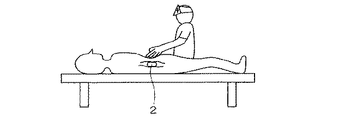
本実施形態の体内観察装置(体内装置)1は、図1に示すように、体内(生体内)に経口投入されるカプセル状の筐体2と、該筐体2の内部に設けられ、この筐体2に設けられた光学的に透明な観察壁面2aを通して体内を観察する観察系(観察手段)3とを具備し、さらに、筐体2の内部には、観察時に観察壁面2aと生体組織とを密着させる流体移送手段の吸引ポンプ装置(異物除去手段、密着補助手段)10が設けられている。
Hereinafter, an embodiment of an in- vivo device concerning the present invention is described based on a drawing.
<First Embodiment>
As shown in FIG. 1, an in-vivo observation device (in-vivo device) 1 of the present embodiment is provided in a capsule-
上記筐体2は、プラスチック等で内部を密閉するように形成され、少なくとも一端側には透明な素材よりなる観察壁面2aがカバー状に設けられている。この観察壁面2aの内側には、体内の各部を撮像する対物レンズ4が配されており、該対物レンズ4の結像位置には、たとえば、CMOSイメージャ等の撮像素子5が配されている。また、対物レンズ4の周囲には、照明光を照射して対物レンズ4の視野範囲を照明するLED6が配されている。すなわち、これら対物レンズ4、撮像素子5及びLED6は、上記観察系3を構成している。
The
上述した吸引ポンプ装置10は、図示しない駆動源やバルブ類を備えたポンプ本体11と、該ポンプ本体11の上流及び下流に接続された管路12,13とを具備して構成される。
ポンプ本体11は、観察壁面2aが設けられた筐体2の前端側に開口する管路12を通して吸引した体液、気体等の流体(以下、「体液」と呼ぶ)を、筐体2の後端に開口する管路13を通して後方へ流出させる機能を有している。この結果、吸引ポンプ装置10が筐体2の前方に存在している体液を開口部(一方の開口部)12aから吸液して後方の開口部(他方の開口部)13aから排液するので、筐体2の前方では、生体組織を吸引して観察壁面2aに密着させた状態としての観察が可能となる。このように生体組織が吸引されて観察壁面2aに密着する現象は、たとえば腸のように比較的細い管状の臓器において、特に、先端が閉塞しているような管状の臓器において有効となる。
なお、上述した吸引ポンプ装置10は、ポンプ本体11を逆転させることにより、筐体2の後端側の開口部13aから前端側の開口部12aに体液を流すこともできる。
The
The pump
The above-described
さらに、筐体2の内部には、上記観察系3を制御する制御部20と、観察系3で取得した撮像画像を記録するメモリ21と、観察系3で取得した撮像画像に基づいて体内観察装置1が所定の部位、たとえば、腸内に達したか否かを判断する判断部22と、上述した各構成品に電力を供給する電源として設けられた電池23とを備えている。
判断部22は、体内観察装置1が腸内に達したと判断すると、その旨の信号を制御部20に送る機能を有している。制御部20は、この信号を受けて上記吸引ポンプ装置10を作動すると共に、観察系3により取得した撮像画像を上記メモリ21に記録するようになっている。
Further, inside the
When the
このように構成された体内観察装置1により、体内を観察する場合について、以下に図2を参照して説明する。なお、本実施形態においては、体内観察装置1が観察対象となる腸内位置に達したときに、吸引ポンプ装置1を作動して観察壁面2aに生体組織を密着させて詳細な観察を行うよう設定している。
図示しない患者に経口投入された体内観察装置1は、消化管に沿って体内を移動する。なお、この際、図示しないスイッチが入るようになっており、電池23から各構成品に電力が供給される。また、制御部20は、体内を撮像するよう観察系3を作動させる。
ここで、体内観察装置1が腸内に達した場合には、判断部22が、観察系3で撮像した撮像画像に基づいて、たとえば、撮像画像に腸内特有のヒダ状の組織が確認されたことを受けて腸内に達したと判断する。
The case where the inside of the body is observed with the in-
The in-
Here, when the in-
判断部22は、腸内に達したと判断すると、その旨の信号を発信して制御部20に知らせる。該制御部20は、この信号を受けて吸引ポンプ装置10を作動させると共に、観察系3で撮像した撮像画像をメモリ21に記録するよう制御を行う。
最初に、制御部20の制御信号により、吸引ポンプ装置10を作動させる。この場合の吸引ポンプ装置10は、図2(a)に示すように、筐体2の前方から吸引した体液を後方へ排出するように正転方向の運転がなされる。従って、観察壁面2aの前方(観察方向前方)に存在する体液は、ポンプ本体11が運転されて発生する吸引力を受けて、開口部12aから管路12内に流入する。この体液は、管路12を通ってポンプ本体11内に導かれた後、さらにポンプ本体11から吐出されて管路13を通り、開口部13aから筐体2の後方へ排液される。この時、腸内に存在している食物残渣等の異物についても、体液の流動と共に筐体後方へ排出される。
When the
First, the
上述した吸引ポンプ装置10の運転を継続することにより、図2(b)に示すように、体内観察装置1の観察方向前方に存在している体液が減少すると共に、腸の内壁が負圧により開口部12aの方向へ吸引される。この結果、図2(c)に示すように、腸内壁の生体組織が開口部12aを設けてある観察壁面2aに密着するので、観察系3は、体液や食物残渣等の異物を介することなく良好な視界のもとで生体組織を直接観察することができるようになる。そして、このような密着状態の生体組織を観察することにより、鮮明な撮像画像をメモリ21に記録することができる。
By continuing the operation of the
こうして観察が終了した後には、ポンプ本体11を逆転させることにより、筐体2の後方に排出した体液等を前方へ戻してやる。このようなポンプ本体11を逆転作動させる指示は、たとえば体外から無線信号を筐体2内の制御部20等へ送信することにより行うことができる。
上述したポンプ本体11を逆転作動するための指示手段としては、無線信号の他にも、たとえば図3に示すように、ポンプ本体11の適所に圧力センサ16を内蔵しておき、その検出圧力を利用してもよい。この場合、圧力センサ16が所定値以上の高圧を検出した時、ポンプ本体11を自動的に正転運転から逆転運転へ移行するようにしてもよいし、あるいは、ポンプ本体11の正転運転を停止すると共に図示しないバルブ類を開放し、開口部12aと開口部13aとの間を連通状態として体液等が自由に流通できるようにしてもよい。なお、圧力センサ16の設置位置については、ポンプ本体11に限定されることはなく、管路12,13の途中であってもよい。
また、観察系3で撮影した画像の明るさを検出することにより、画像の明るさが所定値(閾値)以上に明るくなった時点で生体組織が吸引されて観察壁面2aに密着するまで近づいたと判断し、ポンプ本体11の正転運転を停止したり、あるいは、正転運転から逆転運転に移行するようにしてもよい。
After the observation is thus completed, the body fluid discharged to the rear of the
As an instruction means for reversely operating the pump
Further, by detecting the brightness of the image taken by the
上述した体内観察装置1によれば、密着補助手段として設けた吸引ポンプ装置10を作動して観察対象となる生体組織を観察壁面2aに密着させ、観察壁面2aから直接生体組織の観察を行うことができるので、腸内の洗腸等を行わなくても体液等の異物の影響を受けることなく鮮明な画像から生体組織の状態を確実に認識することができる。特に、患者が炎症性腸疾患等の疾病を有している場合には、洗腸による症状の悪化を防止しつつ腸内の状態を確実に観察することができる。また、腸内の全長にわたって観察を行うことができるので、従来の内視鏡検査では観察を行うことが困難であった位置、たとえば、肛門から十分離れた位置でも確実に観察を行うことができる。
According to the in-
また、このような体内観察装置1においては、ポンプ本体11の駆動をパルス駆動とすることが好ましい。すなわち、ポンプ本体11を継続運転して体液を吸引すると、吸引力が強くなりすぎたり、あるいは、消費電力が大きくなって電池23の容量に問題が生じることも考えられる。このため、パルス駆動を採用することにより、ポンプ本体11の運転がパルスに応じた断続運転となり、吸引力の調整や省エネルギー運転が容易になる。
Moreover, in such an in-
なお、本実施形態においては、判断部22が観察系3で撮像した撮像画像に基づいて腸内に達したか否かを判断し、該判断に応じて吸引ポンプ装置10を作動させたが、これに限られず、たとえば、生体外で体内観察装置1の体内位置を確認し、所望する位置に達したときに信号を送り、該信号を受けたときに、吸引ポンプ装置10を作動するように構成しても構わない。さらに、この際、制御部20が、該信号を受けたときに観察系3を作動するように設定しても構わない。こうすることで、観察を希望する位置でのみ観察系3を作動させることができるので、省電力化を図ることができる。
In the present embodiment, the
<第2の実施形態>
次に、本発明に係る体内装置の第2の実施形態について、図4及び図5を参照して説明する。なお、第2の実施形態において上述した第1の実施形態と同一の構成要素については、同一の符号を付しその詳細な説明は省略する。
図4に示す第2の実施形態では、体内観察装置(体内装置)1Aの筐体2が、観察壁面2aの周囲から観察方向へ向けて突出する筒状部材として、フード7を備えている。このフード7は、観察方向の先端を開口させて観察壁面2aの開口部12aから体液を吸引できるようになっている。
<Second Embodiment>
Next, a second embodiment of the in- vivo device according to the present invention will be described with reference to FIGS. In addition, in the second embodiment, the same components as those in the first embodiment described above are denoted by the same reference numerals, and detailed description thereof is omitted.
In the second embodiment shown in FIG. 4, the
このようなフード7を設けることにより、体内観察装置1Aの観察方向先端部が観察対象の生体組織にある程度近づいた場合、フード7によって吸引領域がある程度まで制限されるので、効率よく確実に吸い寄せることができる。
また、上述したフード7に代えて、たとえば図5に示す体内観察装置(体内装置)1A′のように、観察壁面2aの周囲から観察方向へ突出する筒状部材を筐体2の先端部に着脱自在としたフード7Aを採用してもよい。このような構成とすれば、体内観察装置1A′の用途、すなわち観察対象となる生体組織の形状や位置等に応じて最適な形状のフード7Aを適宜選択交換して使用することができる。なお、図5に示した着脱自在のフード7Aは、先端の開口部を傾斜させて開口部12a側を短くした形状とされる。
また、上述したフード7,7Aの全体、あるいは先端部近傍のみを柔軟な材質で制作することにより、吸引時に接触する生体組織に悪影響を及ぼすことが改善されるので、生体組織を無理なく吸引して観察することが可能になる。
By providing such a
Further, instead of the
In addition, since the
<第3の実施形態>
続いて、本発明に係る体内装置の第3の実施形態について、図6及び図7を参照して説明する。なお、第3の実施形態において上述した第1及び第2の実施形態と同一の構成要素については、同一の符号を付しその詳細な説明は省略する。
図6に示す第3の実施形態では、体内観察装置(体内装置)1Bが、カプセル形状とした筐体2の一側面部に形成した観察壁面2a′を備えた構成とされる。この観察壁面2a′は、筐体2の側面に形成した凹部に設けられている。そして、この観察壁面2a′には、吸引ポンプ装置10に接続された管路12の開口部12aが配設されており、ポンプ本体11の作動により開口部12aから吸引した体液は、略円形断面となる筐体2の直径方向に延びる管路12,13を通って開口部13aから排出される。
<Third Embodiment>
Subsequently, a third embodiment of the in- vivo device according to the present invention will be described with reference to FIGS. In addition, about the component same as the 1st and 2nd embodiment mentioned above in 3rd Embodiment, the same code | symbol is attached | subjected and the detailed description is abbreviate | omitted.
In the third embodiment shown in FIG. 6, the in-vivo observation device (in-vivo device) 1B includes an
このような構成とすれば、横長となるカプセル形状の体内観察装置1Bが安定した状態で外周面側の生体組織に係止されるので、吸引ポンプ装置10の作動により、体液と共に開口部12aへ向けて吸引された生体組織が観察壁面2a′に密着する。従って、体内装置1Bが腸のような管状臓器を観察する場合、特に、水平または水平に近い部分の生体組織を観察する場合には、体内観察装置1Bの安定した観察姿勢を容易に維持することができるので、確実な観察を行って鮮明な撮像画像を得ることができる。
また、上述した側面部の観察壁面2a′を備えた体内観察装置においては、たとえば図7に示す体内観察装置(体内装置)1B′のように、凹部とした観察壁面2a′の周囲を取り囲むようにして異物除去手段のブラシ8を設けることが好ましい。このブラシ8は、適当な密度で筐体2の外周面(側面)から突出した状態に設けられたものであり、体内観察装置1B′の移動時に進行方向前方の異物を除去するだけでなく、開口部12aから体液等が除去された観察領域内に異物が侵入するのを防止することもできる。従って、ブラシ8のような異物除去手段は、吸引ポンプ装置10の負担を軽減すると共に、良好な観察環境の維持に有効である。
With such a configuration, the horizontally long capsule-shaped in-
Further, in the in-vivo observation device provided with the above-described
<第4の実施形態>
続いて、本発明に係る体内装置の第4の実施形態について、図8を参照して説明する。なお、第4の実施形態において上述した第1ないし第3の実施形態と同一の構成要素については、同一の符号を付しその詳細な説明は省略する。
この実施形態の体内観察装置(体内装置)1Cは、筐体2の側面に外径拡張手段のバルーン30を設けたものである。このバルーン30、拡張時に体内観察装置1Cの外径を拡大して、特に管腔の大きな臓器を塞ぐため、筐体2の側面(外周面)を全周にわたって取り囲むように設けられたリング状の部材である。
<Fourth Embodiment>
Next, a fourth embodiment of the internal device according to the present invention will be described with reference to FIG. In addition, about the component same as the 1st thru | or 3rd embodiment mentioned above in 4th Embodiment, the same code | symbol is attached | subjected and the detailed description is abbreviate | omitted.
The in-vivo observation device (in-vivo device) 1C of this embodiment is provided with a
バルーン30の拡張は、筐体2の内部に設置された拡張手段31から管路32を介して圧縮ガス等の流体を供給することにより行われる。ここで、拡張手段31は、圧縮ガスを貯蔵するボンベ等の容器に開閉弁を備えたものでもよいし、あるいは、吸引ポンプ装置10で吸引した体液をバルーン30内に送り込んで膨らませるものでもよい。
このようなバルーン30の拡張は、吸引ポンプ装置10と同様に、所定の条件で制御部20から出力される信号や生体外からの信号を受けて、拡張手段31または吸引ポンプ装置10が作動して実施される。そして、バルーン30が拡張して管腔に密着すると、管腔内がバルーン30を境にして分離されるので、吸引ポンプ10による体液の吸引を効率よく行うことができる。
Expansion of the
In the expansion of the
<第5の実施形態>
さて、これまで説明した実施形態においては、観察時に観察壁面が生体組織に密着した状態とする密着補助手段を体内装置(筐体)内に設けたものであったが、以下に説明する実施形態では、体内装置自体の自重を利用して生体組織に密着させている。すなわち、観察時に観察壁面と生体組織とを密着させる密着補助手段は、体液と体内装置との比重差となる。
<Fifth Embodiment>
In the embodiment described so far, the closet assisting means for providing the observation wall surface in close contact with the living tissue at the time of observation is provided in the in- vivo device (housing). Then, it is made to contact | adhere to a biological tissue using the dead weight of the internal body apparatus itself. That is, the adhesion assisting means for bringing the observation wall surface and the living tissue into close contact with each other becomes a specific gravity difference between the body fluid and the in- vivo device .
図9及び図10は、たとえば胃のように大きな臓器内を観察する体内観察装置(体内装置)1Dを示している。この体内観察装置1Dは、生体内に存在する体液の比重より大きな比重に設定されている。すなわち、図示の例では、カプセル全体の比重を胃液より大きく設定した体内観察装置1Dが、自重によって胃液中で確実に沈下するので、胃壁の生体組織に密着した状態で胃液に視界を妨げられることなく観察できる。この場合、体内観察装置1Dを飲み込んだ患者が適宜体位を変化させることにより、体内観察装置1Dは自重により低い位置へと移動するので、胃のように広い臓器内でもまんべんなく生体組織を観察することができる。
なお、この場合の体内観察装置1Dは、上述した各体内観察装置の比重設定を変更して使用してもよいし、あるいは、吸引ポンプ装置10を取り除いたものでもよい。
9 and 10 show an in-vivo observation device (in-vivo device) 1D for observing the inside of a large organ such as the stomach. This in-
Note that the in-
上述した体内観察装置1Dは、その重心を観察壁面2a側に偏心させておくことが好ましい。
このように重心を観察壁面2a側とする体内観察装置(体内装置)1D′は、図10に示すように、たとえば重り9を設けて重心が観察壁面2a側に移動するよう調整したり、あるいは、筐体2内に収納される各種構成部品の配置を工夫して重心位置を調整すればよい。このような構成により、体液中を沈下する際に重力で下向きとなった観察壁面2aが生体組織側を向いた状態で密着するので、より確実な観察が可能となる。
The in-
In this way, the in-vivo observation device (in-body device) 1D ′ having the center of gravity as the
<第6の実施形態>
続いて、観察時に観察壁面を生体組織に密着させる密着補助手段が、生体外からの作用として圧力を用いた場合について説明する。
図11に示す例では、生体内に経口投入した体内観察装置1が所望の観察位置に到達したら、観察対象の臓器周辺に体外から圧力をかけて観察壁面2aに生体組織を密着させる。このような処置は、医師が画像を見ながら手で圧迫を加えることにより行われるものであるから、特別な道具が不要で簡便に生体組織を観察することができる。なお、この場合の画像は、体内観察装置1から送られてきたものでもよいし、あるいは、体外から入手したものでもよい。
<Sixth Embodiment>
Next, a case where the closet assisting means for closely attaching the observation wall surface to the living tissue during observation uses pressure as an action from outside the living body will be described.
In the example shown in FIG. 11, when the in-
図12(a),(b)に示す例では、医師の手に代えて、密着補助手段として生体外から筐体2に作用を発生する作用発生部を設けた体外密着補助装置の圧迫具40を使用している。この圧迫具40は、筐体2内に設けた発信手段(図示省略)から送信されたデータを受信するアンテナ(受信手段)41が内部に設けられている押圧部42と、受信したデータを画面表示して示す表示部43と、この装置を持って押圧操作するためのグリップ部44とを具備して構成される。
アンテナ41は、体内にある筐体2から送信されてくる画像データや位置検出用の信号等を検出するものであり、図示の構成例では押圧用の先端部42aを曲面とした凸状の押圧部42に内蔵されている。このアンテナ41で検出した画像データや位置検出用の信号は、液晶モニタ、ELモニタ、プラズマモニタ等の表示部43に表示される。
In the example shown in FIGS. 12 (a) and 12 (b), instead of the doctor's hand, the
The
上述した圧迫具40は、たとえば医師が押圧操作用のグリップ部44を手に持ち、表示部43の画面を見ながら患者の体を圧迫する押圧操作を行うものである。以下、その作業手順を簡単に説明する。
患者が筐体2を経口投入してから適当な時間が経過した後、図示しないスイッチをオンにした圧迫具40を患者の体に近づけると、表示部43には、筐体2から送信された画像データと、筐体2の位置情報とが画面表示される。この位置情報に基づいて筐体2が目的の観察位置付近にあることを確認した後、医師は画像データを見ながら圧迫具40を操作し、押圧部42の先端部42aで圧迫する方向や強さなどを判断する。そして、押圧部42で適当な圧迫を加えることにより、筐体2と観察対象の生体組織とを密着させて観察する。
このようにして、圧迫具40を使用した処置を行うことにより、情報入手と圧迫操作とを一つの装置で、しかも同一の視界内において作業を行うことができるので、利便性の向上により医師の作業負担を軽減することができる。
In the above-described
After a suitable time has elapsed since the patient orally put the
In this way, by performing treatment using the
次に、上述した圧迫具40の第1変形例を図13に示して説明する。なお、上述した圧迫具40と同一の構成要素については、同一の符号を付しその詳細な説明は省略する。
さて、第1変形例の圧迫具40Aは、押圧部42内に適宜オン・オフ可能な電磁石(電磁コイル)45を備えている点が異なっている。また、このような圧迫具40Aと対にして使用される筐体2については、圧迫具40A側の磁気吸引に引き寄せられる磁石14が必要となる。この磁石14は、専用に追加して設けたものでもよいが、電磁石45により磁気吸引できる金属製等の内蔵部品を利用したものでもよい。すなわち、この場合の電磁石45が作用発生部の磁場発生装置となり、磁石14が被作用部となる。なお、磁石14に代えて、強磁性体を使用することも可能である。
Next, a first modification of the above-described
Now, the
このような構成を採用することにより、観察対象位置で圧迫具40Aの適所に設けた図示省略の電磁石用スイッチをオンにすれば、電磁石45に通電されて磁気吸引力が発生する。このため、体内の観察位置にある筐体2は、磁石14が磁気吸引されて圧迫具40A側に吸い寄せられる。この結果、体内観察装置は管腔内の壁面に密着するので、筐体2と観察対象の生体組織とを密着させて観察することができるようになり、観察時の操作性がより一層向上したものとなる。
By adopting such a configuration, when an electromagnet switch (not shown) provided at an appropriate position of the
続いて、上述した圧迫具40の第2変形例を図14に示して説明する。なお、上述した圧迫具40,40Aと同一の構成要素については、同一の符号を付しその詳細な説明は省略する。
さて、第2変形例の圧迫具40Bは、上述した第1変形例の圧迫具40Aに加えて、給電用アンテナ46を備えている点が異なっている。また、このような圧迫具40Bと対にして使用される筐体2については、給電用アンテナ46と協働して発電する受電用アンテナ15が必要となる。
Subsequently, a second modification of the above-described
Now, the
このような構成を採用することにより、観察対象位置で電磁石45に通電して電磁吸引力を発生させると、筐体2の磁石14が圧迫具40Bに引き寄せられる。この時、磁石14が磁極を有する永久磁石であれば、電磁石45側の磁極の向きにより給電用アンテナ46と受電アンテナ15とが正対するようになる。すなわち、図14(b)に示すように、電磁石45により形成される押圧部42側の磁極が、先端部42a側をS極とし表示部43側をN極とした場合、体内観察装置側では、磁石14のN極側が電磁石15のS極に吸引される。
By adopting such a configuration, when the
従って、体内観察装置1のN極側に観察壁面2aを配置しておけば、体外からの磁気吸引力を受けて観察壁面2aが管腔の内壁面と正対するので、管腔の生体組織を確実に観察することができる。
また、給電用アンテナ46と受電用アンテナ15とが正対する位置関係になれば、最も発電効率のよい状態となり、筐体内の電池に給電することで、長時間の使用に耐えうるものとなる。
Therefore, if the
In addition, when the
続いて、上述した圧迫具40の第3変形例を図15に示して説明する。なお、上述した圧迫具40,40A、40Bと同一の構成要素については、同一の符号を付しその詳細な説明は省略する。
この第3変形例では、圧迫具40Cの内部に筐体2の位置検出手段として磁気センサ47が設けられている。この磁気センサ47は、筐体2内に設置されている磁石14を検出することにより、筐体2の正確な位置を検出できるようにしたものである。
このような構成としても、比較的簡易な構成で生体内における筐体2の現在位置を正確に認識することができるので、体外から適切な位置に押圧を加えて筐体2を管腔内の壁面に密着させて観察することができる。
Next, a third modification of the above-described
In the third modification, a
Even with such a configuration, the current position of the
<第7の実施形態>
ところで、上述した各実施形態においては、筐体2を観察したい生体組織に密着させる密着補助手段を有し、体液等により視界が妨げられるのを防止して良好な観察画像を得るものであったが、以下の実施形態では、上述した筐体2が目的の生体組織に密着して正確に投薬する投薬手段を備えているものを示して説明する。なお、以下の説明で使用する図面については、上述した各実施形態の観察系、密着補助手段及び制御部等を省略し、主に投薬手段のみを示す。
<Seventh Embodiment>
By the way, in each of the above-described embodiments, there is provided an adhesion assisting means for bringing the
図16に示す投薬手段50は、筐体2の外周面に開口する投薬開口(投薬開口部)51aを備えたシリンダ室51内に薬剤を染み込ませたスポンジ状の薬剤収納部52を設置し、この薬剤収納部52を筐体2の内側からピストン53で圧縮することにより薬剤を押し出して投薬するように構成されている。この場合の薬剤収納部52は、筐体2内に薬剤を貯蔵して搬送する薬剤貯蔵・搬送手段として機能するものである。
A
このような投薬手段50による投薬は、上述した観察手段3により密着した生体組織が投薬対象であることを確認した後、たとえば制御部20からの投薬信号や体外からの投薬信号等により、ピストン53を作動させて投薬する。すなわち、薬剤収納部52が投薬対象となる患部の生体組織に密着した状態でピストン53をシリンダ室51内に押し込んで圧力をかけると、薬剤収納部52に染み込むように貯蔵されている薬剤が投薬開口51aから押し出されるので、患部の生体組織に対して薬剤を直接かつ正確に塗布することができる。
For such dosing by the dosing means 50, after confirming that the living tissue adhered by the observation means 3 is a dosing object, the
次に、上述した投薬手段50の第1変形例を図17に示して説明する。なお、上述した図15の投薬手段50と同一の構成要素については、同じ符号を付しその詳細な説明は省略する。
第1変形例の投薬手段50Aは、薬剤貯蔵・搬送部材として機能する薬剤収納部52の投薬開口51aに、微小な針54を複数設けておく。この針54は密着により生体組織に刺さるので、この状態からピストン53を押し込んで圧力をかけると、薬剤収納部52内の薬剤が押し出されて針54から患部の生体組織に直接注入される。従って、患部の生体組織に対して正確に薬剤を注入して投薬するので、効率のよい投薬が可能になる。
Next, a first modification of the above-described dosing means 50 will be described with reference to FIG. Note that the same components as those in the
The
ところで、この場合の薬剤収納部52については、上述したスポンジ状の採用が可能であることは勿論である。しかし、これに限定されることはなく、たとえばピストン53の圧力に耐えて投薬開口51aを塞ぐことができるようシリンダ室51に固定された板状部材に、複数の針54を設けたものでもよい。
By the way, it is needless to say that the above-described sponge-like shape can be adopted for the
続いて、上述した投薬手段50の第2変形例を図18に示して説明する。なお、上述した投薬手段及びその変形例と同一の構成要素については、同じ符号を付しその詳細な説明は省略する。
第2変形例の投薬手段50Bでは、薬剤貯蔵・搬送手段の薬剤収納部53に、薬剤をしみこませたゲル状の物質を貯蔵する。そして、投薬対象の近傍でピストン53を作動させることにより、この物質が押し出されて患部近傍に放出されるため、患部の生体組織に薬剤を含んだゲル状の物質が粘着する。この結果、ゲル状の物質が長時間にわたって患部に滞在するので、この物質から徐々に薬剤が放出されることとなり、長時間にわたる投薬が可能となる。
Subsequently, a second modification of the above-described
In the medication means 50B of the second modification, a gel substance impregnated with a medicine is stored in the
また、図示の例では、筐体2の外周壁面を利用してシリンダ室を形成し、このシリンダ室が投薬管路55を備えた壁面56で区画された空間を薬剤貯蔵用の薬剤収納部52としている。なお、投薬管路55は薬剤収納部52と筐体2の外部との間を連通状態とし、その先端が筐体2の壁面に開口して薬剤投入口(薬剤開口部)55aとなるので、ピストン53の作動により圧縮されて押し出された薬剤は、薬剤投入口55aから患部近傍へ放出される。
In the illustrated example, a cylinder chamber is formed using the outer peripheral wall surface of the
続いて、上述した投薬手段50の第3変形例を図19に示して説明する。なお、上述した投薬手段及びその変形例と同一の構成要素については、同じ符号を付しその詳細な説明は省略する。
第3変形例の投薬手段50Cでは、薬剤収納部52Aに貯蔵したゲル状の薬剤を電気泳動により筐体2の表面に導き、密着する生体組織に直接塗布するようになっている。この場合、薬剤収納部52Aには、電源57に接続された正極58及び負極59の電極が配設されている。
Then, the 3rd modification of the medication means 50 mentioned above is shown in FIG. 19, and is demonstrated. In addition, about the same component as the medication means mentioned above and its modification, the same code | symbol is attached | subjected and the detailed description is abbreviate | omitted.
In the medication means 50C of the third modified example, the gel-like medicine stored in the
正極58は、薬剤収納部52Aの外周面側となる投薬面側に、すなわち筐体2に開口する投薬開口60側に配設されている。また、負極59は、筐体2の中心側となる薬剤収納部52Aの底面に配設されている。従って、筐体2が所定の患部位置に到達してから電源57をオンにして通電すると、正極58及び負極59間に電気泳動が生じるので、ゲル状の薬剤はゆっくりと投薬開口60に導かれ、筐体2に密着する生体組織に直接塗布される。このため、薬剤収納部52A内の薬剤を、長時間及び広範囲にわたって、確実に患部の生体組織に塗布することができる。
The
続いて、上述した投薬手段50の第4変形例を図20に示して説明する。なお、上述した投薬手段及びその変形例と同一の構成要素については、同じ符号を付しその詳細な説明は省略する。
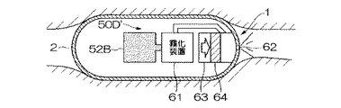
第4変形例の投薬手段50Dでは、薬剤貯蔵・搬送手段として設けた容器の薬剤収納部52Bに貯蔵した薬剤を噴霧装置61で霧化してから放出する。このような霧化装置61を備えた構成とすれば、薬剤を拡散させて生体組織の広範囲にわたって投薬することができる。なお、図中の符号62は、筐体2に開口した放出口である。
Then, the 4th modification of the medication means 50 mentioned above is shown in FIG. 20, and is demonstrated. In addition, about the same component as the medication means mentioned above and its modification, the same code | symbol is attached | subjected and the detailed description is abbreviate | omitted.
In the medication unit 50D of the fourth modified example, the medicine stored in the
また、上述した第4変形例の投薬手段50Dは、図21に示す第5変形例の投薬手段50D′のように、霧化した薬剤を圧縮して押し出すことが好ましい。すなわち、霧化装置61で霧化された薬剤をシリンダ63内を摺動するピストン64で加圧放出することにより、単に霧化して放出する場合と比較して、より一層広範囲にわたって投薬することができる。このような加圧放出は、特に、腸のような長い臓器での投薬に適している。
Moreover, it is preferable that the medication means 50D of the fourth modification described above compresses and extrudes the atomized medicine like the medication means 50D ′ of the fifth modification shown in FIG. In other words, the medicine atomized by the
続いて、上述した投薬手段50の第6変形例を図22に示して説明する。なお、上述した投薬手段及びその変形例と同一の構成要素については、同じ符号を付しその詳細な説明は省略する。
第6変形例の投薬手段50Eでは、投薬前に空気等を放出して患部表面に存在する体液等を除去する異物除去手段として、圧縮空気放出装置(空気放出手段)70を備えている。この圧縮空気放出装置70は、ピストン71がシリンダ72内の空気を圧縮して放出口73から患部付近に噴射するものであり、このような空気の噴射圧力により、生体組織の表面に付着している体液等の異物を除去することができる。従って、筐体2の観察系3で露出した患部の生体組織を確認するとともに、確実に投薬することができる。なお、このような異物除去手段を利用して患部周辺の異物を除去し、上述した観察系3に良好な視野を確保することもできる。
Subsequently, a sixth modification of the above-described
The
また、上述した異物除去手段を備えている場合には、異物除去及び投薬の順序で処置を実施する。図22に示した構成例では、上述した圧縮空気放出装置70と同様に構成された薬剤放出装置65を備えている。この場合、圧縮空気放出装置70で異物除去を行った後、薬剤放出装置65を作動させ、シリンダ66内に貯蔵している薬剤がピストン67に圧縮される。従って、薬剤収納部としても機能するシリンダ66の薬剤は、ピストン67の圧縮を受けて放出口62から筐体2の外部へ放出され、異物の除去された生体組織に確実に投薬される。
Further, when the foreign matter removing means described above is provided, the treatment is performed in the order of foreign matter removal and medication. The configuration example shown in FIG. 22 includes a
続いて、上述した投薬手段50の第7変形例を図23に示して説明する。なお、上述した投薬手段及びその変形例と同一の構成要素については、同じ符号を付しその詳細な説明は省略する。
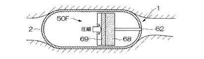
第7変形例の投薬手段50Fは、異物除去及び投薬の順序で自動的に処置して投薬を行うように構成したものである。この投薬手段50Fは、シリンダ68及びピストン69を具備してなり、シリンダ68内に貯蔵した空気及び薬剤をピストン69で押し出すように構成されている。すなわち、シリンダ68のピストン69側に薬剤を貯蔵し、筐体2に開口する放出口62側に空気を貯蔵しておくことで、放出口62から最初に空気を放出した後、続けて薬剤を自動的に放出することができる。従って、生体組織表面に存在する異物を最初に除去してから、投薬対象の生体組織に対して直接、薬剤を自動的に投薬することができる。
Subsequently, a seventh modification of the above-described dosing means 50 will be described with reference to FIG. In addition, about the same component as the medication means mentioned above and its modification, the same code | symbol is attached | subjected and the detailed description is abbreviate | omitted.
The dosing means 50F of the seventh modified example is configured to perform dosing by automatically treating in the order of foreign substance removal and dosing. This dosing means 50 </ b> F includes a
続いて、上述した投薬手段50の第8変形例を図24に示して説明する。なお、上述した投薬手段及びその変形例と同一の構成要素については、同じ符号を付しその詳細な説明は省略する。
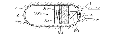
第8変形例の投薬手段50Gは、体外から磁石を近づけることで開閉する磁気応答バルブ80を用いたことに特徴がある。この磁気応答バルブ80は、薬剤を貯蔵したシリンダ81の出口から放出口62に連通する薬剤出口流路に配設されている。なお、シリンダ81内のピストン82は、バネ83により薬剤を押し出す方向の付勢を受けている。
Subsequently, an eighth modification of the above-described dosing means 50 will be described with reference to FIG. In addition, about the same component as the medication means mentioned above and its modification, the same code | symbol is attached | subjected and the detailed description is abbreviate | omitted.
The dispensing means 50G of the eighth modification is characterized in that a magnetic response valve 80 that opens and closes by bringing a magnet closer from the outside of the body is used. The magnetic response valve 80 is disposed in a drug outlet channel that communicates with the
このような構成の投薬手段50Gは、磁気応答バルブ80を閉じた状態でシリンダ81内に薬剤を貯蔵している。従って、筐体2が投薬対象の患部に到達したことを確認したら、体外から患部付近に磁石を近づけて磁気応答バルブ80を開とする。この結果、バネ83の付勢を受けたピストン82が薬剤を押し出すので、放出口62から生体組織に投薬される。
The medication means 50G having such a configuration stores the medicine in the
以上説明したように、本発明の体内装置は、観察系3の良好な観察視野を確保するため、観察対象の生体組織に観察壁面を密着させて体液等の異物を除去する密着補助手段を備えたものである。
また、体内装置が、生体組織に密着した状態で薬剤を投薬する投薬手段を備えることで、目的の患部に対して正確かつ確実な投薬が可能になる。
なお、本発明は上述した実施の形態に限定されることはなく、本発明の要旨を逸脱しない範囲内において適宜変更することができる。
As described above, the in- vivo device of the present invention includes a close-up assisting means for removing a foreign substance such as a bodily fluid by bringing an observation wall into close contact with a living tissue to be observed in order to ensure a good observation field of the
In addition, since the intracorporeal device includes a dosing unit that dispenses the drug in a state of being in close contact with the living tissue, accurate and reliable dosing can be performed on the target affected part.
In addition, this invention is not limited to embodiment mentioned above, In the range which does not deviate from the summary of this invention, it can change suitably.
1,1A〜1D,1A′,1B′,1D′体内観察装置(体内装置) 2筐体 2a 観察壁面 3観察系(観察手段) 4対物レンズ 5撮像素子 6LED 7,7Aフード(筒状部材) 8ブラシ(異物除去手段) 9重り 10吸引ポンプ装置(異物除去手段、密着補助手段) 11ポンプ本体(異物除去手段、流体移送手段) 12,13管路 12a(一方の開口部) 13a開口部(他方の開口部) 14磁石 15受電用アンテナ 16圧力センサ 20制御部 21メモリ 22判断部 23電池(電源) 30バルーン(外径拡張手段) 31拡張手段 32管路 40,40A,40B,40C圧迫具(密着補助手段) 41アンテナ(受信手段) 42押圧部 42a先端部 43表示部 44グリップ部 45電磁石(磁場発生装置) 46給電用アンテナ 47磁気センサ(位置検知手段) 50,50A〜50G,50D′投薬手段 51シリンダ室 51a投薬開口(投薬開口部) 52、52A,52B薬剤収納部 53ピストン 54針 55投薬管路 55a薬剤投入口(投薬開口部) 56壁面 57電源 58正極 59負極 60投薬開口 61噴霧装置 62放出口 63薬剤シリンダ 64,67,69、71,82ピストン 65薬剤放出装置 66,68,72,81シリンダ 70圧縮空気放出装置(空気放出手段) 73放出口 80磁気応答バルブ 83バネ
1, 1A to 1D, 1A ', 1B', 1D 'In-vivo observation device (in-vivo device) 2 Housing 2a Observation wall 3 Observation system (observation means) 4 Objective lens 5 Imaging element 6 LED 7, 7A Hood (tubular member) 8 brushes (foreign matter removing means) 9 weights 10 suction pump devices ( foreign matter removing means, close contact assisting means) 11 pump body ( foreign matter removing means, fluid transfer means) 12, 13 pipeline 12a (one opening) 13a opening ( The other opening) 14 magnets 15 power receiving antenna 16 pressure sensor 20 control unit 21 memory 22 determination unit 23 battery (power source) 30 balloon (outer diameter expansion unit) 31 expansion unit 32 conduit 40, 40A, 40B, 40C compression tool (adhesion aiding means) 41 antenna (receiving means) 42 pressing portion 42a tip 43 display unit 44 grip portion 45 electromagnet (magnetic field generator) 46 feed antenna 4 A magnetic sensor (position detecting means) 50,50A~50G, 50D 'administration means 51 the cylinder chamber 51a dosing opening (dosing openings) 52, 52A, 52B medicine container portion 53 the piston 54 needle 55 dosing pipe 55a agent inlet (dosing (Opening) 56 wall surface 57 power source 58 positive electrode 59 negative electrode 60 dosing opening 61 spraying device 62 discharge port 63 drug cylinder 64, 67, 69, 71, 82 piston 65 drug discharge device 66, 68, 72, 81 cylinder 70 compressed air discharge device (Air release means) 73 Release port 80 Magnetic response valve 83 Spring
Claims (13)
前記生体内の組織表面と前記筐体との間の異物を除去するための異物除去手段とを備え、
前記異物除去手段が、前記筐体と前記生体内の組織表面とを密着させることで、前記異物を除去する密着補助手段であることを特徴とする体内装置。 A capsule-like housing that is orally injected into a living body;
Foreign matter removing means for removing foreign matter between the tissue surface in the living body and the housing ,
An intracorporeal device , wherein the foreign matter removing means is an adhesion assisting means for removing the foreign matter by bringing the casing and a tissue surface in the living body into close contact with each other .
前記筐体内に、該筐体の観察壁面を通して前記生体内を観察する観察手段を備え、
前記異物除去手段が、前記観察壁面と前記生体内の組織表面との間の異物を除去することを特徴とする体内装置。 The intracorporeal device of claim 1.
In the casing, provided with an observation means for observing the inside of the living body through the observation wall surface of the casing,
The intracorporeal device, wherein the foreign matter removing means removes foreign matter between the observation wall surface and the tissue surface in the living body.
前記筐体内に、投薬開口部を通して所望の部位に薬剤を投与する投薬手段を備え、
前記異物除去手段が、前記投薬開口部と前記生体内の組織表面との間の異物を除去することを特徴とする体内装置。 The intracorporeal device of claim 1.
A dispensing means for administering a drug to a desired site through a medication opening in the housing is provided,
The intracorporeal device, wherein the foreign matter removing means removes foreign matter between the medication opening and the tissue surface in the living body.
前記筐体内に、前記密着補助手段を備えていることを特徴とする体内装置。 In vivo device according to any one of claims 1 to 3,
An in-vivo device comprising the close-in support means in the housing.
生体外から前記筐体に作用を発生する作用発生部を有する体外密着補助装置と、
を備えていることを特徴とする医療機器。 An intracorporeal device according to any one of claims 1 to 3 ,
An extracorporeal adhesion assisting device having an action generating portion for generating an action on the housing from outside the living body;
A medical device characterized by comprising:
前記密着補助手段は、前記作用発生部が発生した作用を受ける被作用部をさらに有していることを特徴とする医療機器。 The medical device according to claim 5 ,
The medical device according to claim 1, wherein the adhesion assisting means further includes an actuated part that receives an action generated by the action generating part.
前記筐体が、2つの開口部を備え、
前記密着補助手段が、前記一方の開口部で前記生体内の流体を吸引すると共に、吸引した流体を前記他方の開口部から排出する流体移送手段であり、
該流体移送手段によって、前記筐体が前記生体内の組織表面に密着することを特徴とする体内装置。 The intracorporeal device according to claim 4 ,
The housing includes two openings;
The adhesion assisting means is a fluid transfer means for sucking the fluid in the living body through the one opening and discharging the sucked fluid from the other opening,
An intracorporeal device wherein the casing is brought into close contact with the tissue surface in the living body by the fluid transfer means.
装置全体の比重は、生体内に存在する前記流体の比重よりも大きく設定されていることを特徴とする体内装置。 The intracorporeal device according to claim 4 ,
The internal device is characterized in that the specific gravity of the entire device is set larger than the specific gravity of the fluid existing in the living body.
前記作用発生部が、前記生体に押し付ける押圧部であることを特徴とする医療機器。 The medical device according to claim 5 ,
The medical device, wherein the action generating unit is a pressing unit that presses against the living body.
前記作用発生部が磁場発生装置であり、
前記被作用部が、永久磁石または強磁性体であることを特徴とする医療機器。 The medical device according to claim 6 ,
The action generator is a magnetic field generator;
The medical device, wherein the affected part is a permanent magnet or a ferromagnetic material.
前記筐体内にデータを送信する送信手段を備え、
前記作用発生部に前記送信手段から送信されたデータを表示する表示部を備えたことを特徴とする医療機器。 The medical device according to claim 5 or 6 ,
A transmission means for transmitting data in the housing;
A medical device comprising a display unit that displays data transmitted from the transmission unit on the action generating unit.
前記体外密着補助装置に前記筐体の位置を検知する位置検知手段を備えたことを特徴とする医療機器。 The medical device according to claim 5 or 6 ,
A medical device comprising a position detecting means for detecting the position of the casing in the extracorporeal close-contact assistance device.
前記筐体内に受電用アンテナを備え、
前記作用発生部に給電用アンテナを備えたことを特徴とする医療機器。 The medical device according to claim 5 or 6 ,
A power receiving antenna is provided in the housing,
A medical device comprising a power feeding antenna in the action generating unit.
Priority Applications (7)
| Application Number | Priority Date | Filing Date | Title |
|---|---|---|---|
| JP2003361782A JP4503979B2 (en) | 2003-10-22 | 2003-10-22 | Internal devices and medical devices |
| US10/952,391 US20050124875A1 (en) | 2003-10-01 | 2004-09-28 | Vivo observation device |
| PCT/JP2004/014488 WO2005032370A1 (en) | 2003-10-01 | 2004-10-01 | Body inside observation device |
| EP04791955A EP1669026A4 (en) | 2003-10-01 | 2004-10-01 | Body inside observation device |
| CN2008100823959A CN101254087B (en) | 2003-10-01 | 2004-10-01 | Body inside observation device |
| US12/050,511 US20080242928A1 (en) | 2003-10-01 | 2008-03-18 | In vivo observation device |
| US12/051,428 US20080234546A1 (en) | 2003-10-01 | 2008-03-19 | In vivo observation device |
Applications Claiming Priority (1)
| Application Number | Priority Date | Filing Date | Title |
|---|---|---|---|
| JP2003361782A JP4503979B2 (en) | 2003-10-22 | 2003-10-22 | Internal devices and medical devices |
Publications (3)
| Publication Number | Publication Date |
|---|---|
| JP2005124708A JP2005124708A (en) | 2005-05-19 |
| JP2005124708A5 JP2005124708A5 (en) | 2006-12-07 |
| JP4503979B2 true JP4503979B2 (en) | 2010-07-14 |
Family
ID=34641619
Family Applications (1)
| Application Number | Title | Priority Date | Filing Date |
|---|---|---|---|
| JP2003361782A Expired - Fee Related JP4503979B2 (en) | 2003-10-01 | 2003-10-22 | Internal devices and medical devices |
Country Status (1)
| Country | Link |
|---|---|
| JP (1) | JP4503979B2 (en) |
Families Citing this family (58)
| Publication number | Priority date | Publication date | Assignee | Title |
|---|---|---|---|---|
| US8836513B2 (en) | 2006-04-28 | 2014-09-16 | Proteus Digital Health, Inc. | Communication system incorporated in an ingestible product |
| US8802183B2 (en) | 2005-04-28 | 2014-08-12 | Proteus Digital Health, Inc. | Communication system with enhanced partial power source and method of manufacturing same |
| US9198608B2 (en) | 2005-04-28 | 2015-12-01 | Proteus Digital Health, Inc. | Communication system incorporated in a container |
| EP2671507A3 (en) | 2005-04-28 | 2014-02-19 | Proteus Digital Health, Inc. | Pharma-informatics system |
| US8912908B2 (en) | 2005-04-28 | 2014-12-16 | Proteus Digital Health, Inc. | Communication system with remote activation |
| WO2006126653A1 (en) * | 2005-05-27 | 2006-11-30 | Olympus Corporation | Device for introduction into subject |
| JP2007000263A (en) * | 2005-06-22 | 2007-01-11 | Pentax Corp | Confocal endoscope |
| SG132553A1 (en) * | 2005-11-28 | 2007-06-28 | Pang Ah San | A device for laparoscopic or thoracoscopic surgery |
| JP5064018B2 (en) * | 2005-12-28 | 2012-10-31 | オリンパスメディカルシステムズ株式会社 | Intra-subject introduction system |
| JPWO2007077922A1 (en) * | 2005-12-28 | 2009-06-11 | オリンパスメディカルシステムズ株式会社 | Intra-subject introduction system and intra-subject observation method |
| JP2009544338A (en) | 2006-05-02 | 2009-12-17 | プロテウス バイオメディカル インコーポレイテッド | Treatment regimen customized to the patient |
| SG175681A1 (en) | 2006-10-25 | 2011-11-28 | Proteus Biomedical Inc | Controlled activation ingestible identifier |
| EP2069004A4 (en) | 2006-11-20 | 2014-07-09 | Proteus Digital Health Inc | Active signal processing personal health signal receivers |
| AU2008210291B2 (en) | 2007-02-01 | 2013-10-03 | Otsuka Pharmaceutical Co., Ltd. | Ingestible event marker systems |
| MY154556A (en) | 2007-02-14 | 2015-06-30 | Proteus Digital Health Inc | In-body power source having high surface area electrode |
| US8932221B2 (en) | 2007-03-09 | 2015-01-13 | Proteus Digital Health, Inc. | In-body device having a multi-directional transmitter |
| EP2063771A1 (en) | 2007-03-09 | 2009-06-03 | Proteus Biomedical, Inc. | In-body device having a deployable antenna |
| US8540632B2 (en) | 2007-05-24 | 2013-09-24 | Proteus Digital Health, Inc. | Low profile antenna for in body device |
| EP2192946B1 (en) | 2007-09-25 | 2022-09-14 | Otsuka Pharmaceutical Co., Ltd. | In-body device with virtual dipole signal amplification |
| CN101808567B (en) * | 2007-09-26 | 2012-09-05 | 奥林巴斯医疗株式会社 | Introduction-into-subject system |
| US9017248B2 (en) | 2007-11-08 | 2015-04-28 | Olympus Medical Systems Corp. | Capsule blood detection system and method |
| JP5031601B2 (en) * | 2008-01-29 | 2012-09-19 | 富士フイルム株式会社 | Capsule endoscope and operation control method of capsule endoscope |
| ES2636844T3 (en) | 2008-03-05 | 2017-10-09 | Proteus Biomedical, Inc. | Ingestible multimode communication systems and markers, and methods to use them |
| JP5314913B2 (en) * | 2008-04-03 | 2013-10-16 | オリンパスメディカルシステムズ株式会社 | Capsule medical system |
| CA2730275C (en) | 2008-07-08 | 2019-05-21 | Proteus Biomedical, Inc. | Ingestible event marker data framework |
| US8540633B2 (en) | 2008-08-13 | 2013-09-24 | Proteus Digital Health, Inc. | Identifier circuits for generating unique identifiable indicators and techniques for producing same |
| CA2750158A1 (en) | 2009-01-06 | 2010-07-15 | Proteus Biomedical, Inc. | Ingestion-related biofeedback and personalized medical therapy method and system |
| KR20110104079A (en) * | 2009-01-06 | 2011-09-21 | 프로테우스 바이오메디컬, 인코포레이티드 | Pharmaceutical dosages delivery system |
| GB2480965B (en) | 2009-03-25 | 2014-10-08 | Proteus Digital Health Inc | Probablistic pharmacokinetic and pharmacodynamic modeling |
| SG10201810784SA (en) | 2009-04-28 | 2018-12-28 | Proteus Digital Health Inc | Highly Reliable Ingestible Event Markers And Methods For Using The Same |
| EP2432458A4 (en) | 2009-05-12 | 2014-02-12 | Proteus Digital Health Inc | Ingestible event markers comprising an ingestible component |
| US8882748B2 (en) * | 2009-10-08 | 2014-11-11 | Palo Alto Research Center Incorporated | Transmucosal drug delivery device and method including chemical permeation enhancers |
| US9017310B2 (en) * | 2009-10-08 | 2015-04-28 | Palo Alto Research Center Incorporated | Transmucosal drug delivery device and method including microneedles |
| TWI517050B (en) | 2009-11-04 | 2016-01-11 | 普羅托斯數位健康公司 | System for supply chain management |
| CN102905672B (en) | 2010-04-07 | 2016-08-17 | 普罗秋斯数字健康公司 | Miniature ingestible device |
| TWI557672B (en) | 2010-05-19 | 2016-11-11 | 波提亞斯數位康健公司 | Computer system and computer-implemented method to track medication from manufacturer to a patient, apparatus and method for confirming delivery of medication to a patient, patient interface device |
| EP2642983A4 (en) | 2010-11-22 | 2014-03-12 | Proteus Digital Health Inc | Ingestible device with pharmaceutical product |
| WO2015112603A1 (en) | 2014-01-21 | 2015-07-30 | Proteus Digital Health, Inc. | Masticable ingestible product and communication system therefor |
| US9756874B2 (en) | 2011-07-11 | 2017-09-12 | Proteus Digital Health, Inc. | Masticable ingestible product and communication system therefor |
| CA2842952C (en) | 2011-07-21 | 2019-01-08 | Proteus Digital Health, Inc. | Mobile communication device, system, and method |
| US9235683B2 (en) | 2011-11-09 | 2016-01-12 | Proteus Digital Health, Inc. | Apparatus, system, and method for managing adherence to a regimen |
| JP5439632B1 (en) | 2012-02-15 | 2014-03-12 | オリンパスメディカルシステムズ株式会社 | Medical system |
| KR20150038038A (en) | 2012-07-23 | 2015-04-08 | 프로테우스 디지털 헬스, 인코포레이티드 | Techniques for manufacturing ingestible event markers comprising an ingestible component |
| MX340182B (en) | 2012-10-18 | 2016-06-28 | Proteus Digital Health Inc | Apparatus, system, and method to adaptively optimize power dissipation and broadcast power in a power source for a communication device. |
| JP2016508529A (en) | 2013-01-29 | 2016-03-22 | プロテウス デジタル ヘルス, インコーポレイテッド | Highly expandable polymer film and composition containing the same |
| WO2014144738A1 (en) | 2013-03-15 | 2014-09-18 | Proteus Digital Health, Inc. | Metal detector apparatus, system, and method |
| EP3968263A1 (en) | 2013-06-04 | 2022-03-16 | Otsuka Pharmaceutical Co., Ltd. | System, apparatus and methods for data collection and assessing outcomes |
| US9796576B2 (en) | 2013-08-30 | 2017-10-24 | Proteus Digital Health, Inc. | Container with electronically controlled interlock |
| US10084880B2 (en) | 2013-11-04 | 2018-09-25 | Proteus Digital Health, Inc. | Social media networking based on physiologic information |
| US11051543B2 (en) | 2015-07-21 | 2021-07-06 | Otsuka Pharmaceutical Co. Ltd. | Alginate on adhesive bilayer laminate film |
| JP6542702B2 (en) * | 2016-03-31 | 2019-07-10 | 英敏 太田 | Stomach space filling device |
| CN109843149B (en) | 2016-07-22 | 2020-07-07 | 普罗秋斯数字健康公司 | Electromagnetic sensing and detection of ingestible event markers |
| EP3531901A4 (en) | 2016-10-26 | 2021-01-27 | Proteus Digital Health, Inc. | Methods for manufacturing capsules with ingestible event markers |
| JP6767084B2 (en) * | 2017-02-14 | 2020-10-14 | 英敏 太田 | Body fluid control device and body fluid control system |
| CA3116906A1 (en) * | 2018-11-02 | 2020-05-07 | Bionaut Labs Ltd. | Magnetomechanic triggering of payload release from miniaturized devices |
| US11534544B2 (en) | 2019-03-22 | 2022-12-27 | Daegu Gyeongbuk Institute Of Science And Technology | Device for conveying biological material |
| KR102173512B1 (en) * | 2019-05-14 | 2020-11-03 | 재단법인대구경북과학기술원 | Device for conveying biological material and capsule-shaped endoscope comprising the same |
| CN110772210B (en) * | 2019-11-08 | 2022-09-20 | 重庆金山医疗技术研究院有限公司 | Diagnosis interaction system and method |
Citations (13)
| Publication number | Priority date | Publication date | Assignee | Title |
|---|---|---|---|---|
| JPS5819233A (en) * | 1981-07-29 | 1983-02-04 | オリンパス光学工業株式会社 | Medical capsule |
| JPH04144533A (en) * | 1990-10-05 | 1992-05-19 | Olympus Optical Co Ltd | Endoscope |
| JPH06142081A (en) * | 1992-11-05 | 1994-05-24 | Olympus Optical Co Ltd | Capsule apparatus for intracavitary diagnosis |
| JPH06160734A (en) * | 1992-11-16 | 1994-06-07 | Mitsubishi Cable Ind Ltd | Side view type endoscope |
| JP2002153419A (en) * | 2000-11-22 | 2002-05-28 | Sanguroo:Kk | Endoscope |
| JP2003038424A (en) * | 2001-07-30 | 2003-02-12 | Olympus Optical Co Ltd | Encapsulated endoscope |
| JP2003093332A (en) * | 2001-09-21 | 2003-04-02 | Olympus Optical Co Ltd | Capsulated medical apparatus |
| JP2003111720A (en) * | 2001-08-29 | 2003-04-15 | Siemens Ag | Equipment for performing minimum invasive diagnostic and invasive in patient body |
| JP2003135389A (en) * | 2001-11-06 | 2003-05-13 | Olympus Optical Co Ltd | Capsule type medical apparatus |
| JP2003135388A (en) * | 2001-10-30 | 2003-05-13 | Olympus Optical Co Ltd | Endoscope apparatus |
| JP2003325441A (en) * | 2002-03-08 | 2003-11-18 | Olympus Optical Co Ltd | Capsule endoscope |
| JP2003325438A (en) * | 2002-05-10 | 2003-11-18 | Olympus Optical Co Ltd | Capsule type medical treatment device |
| JP2004275409A (en) * | 2003-03-14 | 2004-10-07 | Olympus Corp | Ultrasonic capsule endoscope system |
Family Cites Families (1)
| Publication number | Priority date | Publication date | Assignee | Title |
|---|---|---|---|---|
| WO2002095351A2 (en) * | 2001-05-20 | 2002-11-28 | Given Imaging Ltd. | A floatable in vivo sensing device |
-
2003
- 2003-10-22 JP JP2003361782A patent/JP4503979B2/en not_active Expired - Fee Related
Patent Citations (13)
| Publication number | Priority date | Publication date | Assignee | Title |
|---|---|---|---|---|
| JPS5819233A (en) * | 1981-07-29 | 1983-02-04 | オリンパス光学工業株式会社 | Medical capsule |
| JPH04144533A (en) * | 1990-10-05 | 1992-05-19 | Olympus Optical Co Ltd | Endoscope |
| JPH06142081A (en) * | 1992-11-05 | 1994-05-24 | Olympus Optical Co Ltd | Capsule apparatus for intracavitary diagnosis |
| JPH06160734A (en) * | 1992-11-16 | 1994-06-07 | Mitsubishi Cable Ind Ltd | Side view type endoscope |
| JP2002153419A (en) * | 2000-11-22 | 2002-05-28 | Sanguroo:Kk | Endoscope |
| JP2003038424A (en) * | 2001-07-30 | 2003-02-12 | Olympus Optical Co Ltd | Encapsulated endoscope |
| JP2003111720A (en) * | 2001-08-29 | 2003-04-15 | Siemens Ag | Equipment for performing minimum invasive diagnostic and invasive in patient body |
| JP2003093332A (en) * | 2001-09-21 | 2003-04-02 | Olympus Optical Co Ltd | Capsulated medical apparatus |
| JP2003135388A (en) * | 2001-10-30 | 2003-05-13 | Olympus Optical Co Ltd | Endoscope apparatus |
| JP2003135389A (en) * | 2001-11-06 | 2003-05-13 | Olympus Optical Co Ltd | Capsule type medical apparatus |
| JP2003325441A (en) * | 2002-03-08 | 2003-11-18 | Olympus Optical Co Ltd | Capsule endoscope |
| JP2003325438A (en) * | 2002-05-10 | 2003-11-18 | Olympus Optical Co Ltd | Capsule type medical treatment device |
| JP2004275409A (en) * | 2003-03-14 | 2004-10-07 | Olympus Corp | Ultrasonic capsule endoscope system |
Also Published As
| Publication number | Publication date |
|---|---|
| JP2005124708A (en) | 2005-05-19 |
Similar Documents
| Publication | Publication Date | Title |
|---|---|---|
| JP4503979B2 (en) | Internal devices and medical devices | |
| EP1669026A1 (en) | Body inside observation device | |
| US20080234546A1 (en) | In vivo observation device | |
| JP4578740B2 (en) | Capsule medical device | |
| JP4744026B2 (en) | Capsule endoscope and capsule endoscope system | |
| JP4149838B2 (en) | Capsule medical device | |
| JP4733918B2 (en) | Capsule dosing system | |
| JP4716922B2 (en) | Capsule type medical device and drug introduction system using the same | |
| JP3863839B2 (en) | Microcapsule robot and endoscope system | |
| JP4642934B2 (en) | Capsule medical device | |
| JP4526253B2 (en) | In-vivo observation device | |
| US20140228641A1 (en) | Diagnostic capsules, delivery / retrieval systems, kits and methods | |
| JP4642941B2 (en) | Capsule medical device | |
| JPWO2007097393A1 (en) | Capsule endoscope system | |
| JP2003325438A (en) | Capsule type medical treatment device | |
| US20100076261A1 (en) | Examination device | |
| JP2004041709A (en) | Capsule medical care device | |
| WO2004078036A1 (en) | Collecting device of capsule type medical unit and its collecting method | |
| JP2009006154A (en) | Capsule type medical device | |
| JP4129269B2 (en) | Capsule medical device | |
| JP2005131012A (en) | Capsule medication system | |
| JP2006325874A (en) | Capsule ultrasonic endoscope and capsule ultrasonic endoscope system | |
| CN110151110B (en) | Fixable capsule endoscope for monitoring gastrorrhagia and real-time monitoring system for gastrorrhagia | |
| WO2007034712A1 (en) | Device for washing capsule endoscope | |
| JP2005288184A (en) | Capsule endoscope apparatus |
Legal Events
| Date | Code | Title | Description |
|---|---|---|---|
| A521 | Written amendment |
Free format text: JAPANESE INTERMEDIATE CODE: A523 Effective date: 20061018 |
|
| A621 | Written request for application examination |
Free format text: JAPANESE INTERMEDIATE CODE: A621 Effective date: 20061018 |
|
| A521 | Written amendment |
Free format text: JAPANESE INTERMEDIATE CODE: A821 Effective date: 20061019 |
|
| A131 | Notification of reasons for refusal |
Free format text: JAPANESE INTERMEDIATE CODE: A131 Effective date: 20091013 |
|
| A521 | Written amendment |
Free format text: JAPANESE INTERMEDIATE CODE: A523 Effective date: 20091201 |
|
| A521 | Written amendment |
Free format text: JAPANESE INTERMEDIATE CODE: A821 Effective date: 20091202 |
|
| A131 | Notification of reasons for refusal |
Free format text: JAPANESE INTERMEDIATE CODE: A131 Effective date: 20100105 |
|
| A521 | Written amendment |
Free format text: JAPANESE INTERMEDIATE CODE: A523 Effective date: 20100301 Free format text: JAPANESE INTERMEDIATE CODE: A821 Effective date: 20100301 |
|
| TRDD | Decision of grant or rejection written | ||
| A01 | Written decision to grant a patent or to grant a registration (utility model) |
Free format text: JAPANESE INTERMEDIATE CODE: A01 Effective date: 20100406 |
|
| A01 | Written decision to grant a patent or to grant a registration (utility model) |
Free format text: JAPANESE INTERMEDIATE CODE: A01 |
|
| A61 | First payment of annual fees (during grant procedure) |
Free format text: JAPANESE INTERMEDIATE CODE: A61 Effective date: 20100422 |
|
| R151 | Written notification of patent or utility model registration |
Ref document number: 4503979 Country of ref document: JP Free format text: JAPANESE INTERMEDIATE CODE: R151 |
|
| FPAY | Renewal fee payment (event date is renewal date of database) |
Free format text: PAYMENT UNTIL: 20130430 Year of fee payment: 3 |
|
| FPAY | Renewal fee payment (event date is renewal date of database) |
Free format text: PAYMENT UNTIL: 20140430 Year of fee payment: 4 |
|
| S531 | Written request for registration of change of domicile |
Free format text: JAPANESE INTERMEDIATE CODE: R313531 |
|
| R350 | Written notification of registration of transfer |
Free format text: JAPANESE INTERMEDIATE CODE: R350 |
|
| R250 | Receipt of annual fees |
Free format text: JAPANESE INTERMEDIATE CODE: R250 |
|
| R250 | Receipt of annual fees |
Free format text: JAPANESE INTERMEDIATE CODE: R250 |
|
| LAPS | Cancellation because of no payment of annual fees |