JP4166509B2 - Capsule endoscope - Google Patents
Capsule endoscope Download PDFInfo
- Publication number
- JP4166509B2 JP4166509B2 JP2002164786A JP2002164786A JP4166509B2 JP 4166509 B2 JP4166509 B2 JP 4166509B2 JP 2002164786 A JP2002164786 A JP 2002164786A JP 2002164786 A JP2002164786 A JP 2002164786A JP 4166509 B2 JP4166509 B2 JP 4166509B2
- Authority
- JP
- Japan
- Prior art keywords
- capsule
- capsule endoscope
- imaging
- image
- image information
- Prior art date
- Legal status (The legal status is an assumption and is not a legal conclusion. Google has not performed a legal analysis and makes no representation as to the accuracy of the status listed.)
- Expired - Fee Related
Links
Images


Classifications
-
- A—HUMAN NECESSITIES
- A61—MEDICAL OR VETERINARY SCIENCE; HYGIENE
- A61B—DIAGNOSIS; SURGERY; IDENTIFICATION
- A61B1/00—Instruments for performing medical examinations of the interior of cavities or tubes of the body by visual or photographical inspection, e.g. endoscopes; Illuminating arrangements therefor
- A61B1/04—Instruments for performing medical examinations of the interior of cavities or tubes of the body by visual or photographical inspection, e.g. endoscopes; Illuminating arrangements therefor combined with photographic or television appliances
- A61B1/041—Capsule endoscopes for imaging
-
- A—HUMAN NECESSITIES
- A61—MEDICAL OR VETERINARY SCIENCE; HYGIENE
- A61B—DIAGNOSIS; SURGERY; IDENTIFICATION
- A61B5/00—Measuring for diagnostic purposes; Identification of persons
- A61B5/06—Devices, other than using radiation, for detecting or locating foreign bodies ; determining position of probes within or on the body of the patient
- A61B5/065—Determining position of the probe employing exclusively positioning means located on or in the probe, e.g. using position sensors arranged on the probe
-
- A—HUMAN NECESSITIES
- A61—MEDICAL OR VETERINARY SCIENCE; HYGIENE
- A61B—DIAGNOSIS; SURGERY; IDENTIFICATION
- A61B1/00—Instruments for performing medical examinations of the interior of cavities or tubes of the body by visual or photographical inspection, e.g. endoscopes; Illuminating arrangements therefor
- A61B1/00002—Operational features of endoscopes
- A61B1/0002—Operational features of endoscopes provided with data storages
-
- A—HUMAN NECESSITIES
- A61—MEDICAL OR VETERINARY SCIENCE; HYGIENE
- A61B—DIAGNOSIS; SURGERY; IDENTIFICATION
- A61B1/00—Instruments for performing medical examinations of the interior of cavities or tubes of the body by visual or photographical inspection, e.g. endoscopes; Illuminating arrangements therefor
- A61B1/00002—Operational features of endoscopes
- A61B1/00025—Operational features of endoscopes characterised by power management
- A61B1/00036—Means for power saving, e.g. sleeping mode
-
- A—HUMAN NECESSITIES
- A61—MEDICAL OR VETERINARY SCIENCE; HYGIENE
- A61B—DIAGNOSIS; SURGERY; IDENTIFICATION
- A61B2560/00—Constructional details of operational features of apparatus; Accessories for medical measuring apparatus
- A61B2560/02—Operational features
- A61B2560/0204—Operational features of power management
- A61B2560/0209—Operational features of power management adapted for power saving
Description
【0001】
【発明の属する技術分野】
本発明は、カプセル本体に、撮影装置を内蔵し、この撮影装置により体腔内を撮影するようにしたカプセル式内視鏡に関する。
【0002】
【従来の技術とその課題】
内視鏡を食道内に挿入し、病変の有無を直接に観察して検査することは信頼性が高いが、この方法での検査には大掛かりな施設が必要である。それだけでなく、患者や術者の負担も大きかった。従って、内視鏡検査は集団検診などでの一次スクリーニングとしては採用し難いものとされてきた。
【0003】
一般に、集団検診などでの一次スクリーニングとしては最低限、病変可能性を診断できればよいものであって、コスト削減と患者の苦痛と心理的不安が少ない簡便な検査方法であることが重要であった。
【0004】
よって、新たに食道内の病変の有無を直接に観察して的確に診断できる方式を一次スクリーニングのプログラムに採用できる簡便な検査手段の確立が望まれていた。
【0005】
そこで、内視鏡をカプセル状に構成し、そのカプセルを飲み込むことにより、このカプセルが食道を通過中に食道内を撮影し、その画像信号を無線等により、リアルタイムに体外に伝送するカメラ方式のものを提案した。
【0006】
しかし、リアルタイムに画像を伝送する場合のビデオフレームは一般に1秒に2駒と非常に遅いものである。それにも拘わらず、カプセルが食道を通過する時間は1秒程度と非常に短い。その結果、カプセルが食道を通過する間に1枚か2枚程度のフレームしか撮影できない。この程度のフレーム枚数では検査結果を十分に信頼することができず、食道の診断に向かない。また、食道以外の胃、十二指腸、小腸、大腸などの臓器内の病変周辺あるいは関心領域の検査用として撮影する場合にもフレーム枚数が少なく精査できないという不具合があった。
【0007】
本発明の目的はカプセルが食道や体内臓器の病変周辺あるいは関心領域を通る短い時間において多くのフレーム枚数の画像が撮影できるカプセル式内視鏡を提供することにある。
【0008】
【課題を解決するための手段】
請求項1に係る発明は、撮像素子、照明手段、画像信号処理回路、画像情報伝送回路および送信用アンテナを、カプセル本体に設け、前記撮像素子で得た信号を前記画像信号処理回路によって処理して画像情報を生成し、この画像情報を、前記画像情報伝送回路および前記送信用アンテナにより体外に送信するカプセル式内視鏡であって、前記カプセル本体の位置を検出する位置検出装置を設け、検出された前記カプセル本体の位置情報に応じて、前記カプセル本体の撮影の形態を制御することを特徴とするカプセル式内視鏡である。
請求項2に係る発明は、前記画像情報を蓄積するメモリを前記カプセル本体に設け、このメモリに蓄積した前記画像情報を、前記体外に送信することを特徴とする請求項1に記載のカプセル式内視鏡である。
請求項3に係る発明は、前記撮影形態が、前記撮像素子による撮像速度、あるいは撮像のオン・オフ動作、あるいは撮影回数によって決定されることを特徴とする請求項1または請求項2に記載のカプセル式内視鏡である。
請求項4に係る発明は、前記位置検出装置が、前記カプセル本体に設けられた電磁波検出センサと、前記体外に設けられた体外プレートからなることを特徴とする請求項1、請求項2または請求項3に記載のカプセル式内視鏡である。
請求項5に係る発明は、前記体外プレートが磁気プレート、あるいは導電プレート、あるいは磁気コイルであることを特徴とする請求項4に記載のカプセル式内視鏡である。
請求項6に係る発明は、前記位置検出装置が、ジャイロ、あるいは加速度センサ、あるいは速度センサを有することを特徴とする請求項1から請求項3のいずれか1項に記載のカプセル式内視鏡である。
請求項7に係る発明は、前記撮像素子が前記カプセル本体の先端部に設けられ、前記カプセル本体の後端部に柔らかい尾を形成したことを特徴とする請求項1から請求項6のいずれか1項に記載のカプセル式内視鏡である。
請求項8に係る発明は、前記撮像素子が前記カプセル本体の先端部に設けられ、前記カプセルの重心が前記先端部に位置することを特徴とする請求項1から請求項7のいずれか1項に記載のカプセル式内視鏡である。
請求項9に係る発明は、前記カプセル本体に、動作スケジュールが設定されたプログラムを設け、前記プログラムの動作スケジュールに従って、前記撮像素子、前記照明手段、前記画像信号処理回路、前記画像情報伝送回路、前記送信用アンテナが制御されることを特徴とする請求項1から請求項8のいずれか1項に記載のカプセル式内視鏡である。
【0009】
【発明の実施の形態】
(第1の実施形態)
図1乃至図5を参照して本発明の第1の実施形態に係るカプセル式内視鏡について説明する。
【0010】
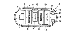
図1はいわゆる小型カメラとして構成したカプセル式内視鏡1を概略的に示す。カプセル式内視鏡1は保護用外皮となる透光性のあるカプセル本体2を備える。カプセル本体2は口から飲み込んで食道を通過できる外形と大きさを有したケースで形成されている。カプセル本体2の内部には密閉した収納室を形成する。図1に示すようにカプセル本体2は中間部分が直径に比べて軸方向に長い、円筒状のものである。カプセル本体2の両端部分はいずれも中空半球状に軸方向外方へ突き出すように形成され、その少なくとも外面は滑らかな形状になっている。カプセル本体2は直径に比べて軸方向に長い形状であるため、飲み込み易いと共に飲み込む向きが軸方向に決まり易い。
【0011】
図1に示すようにカプセル本体2の収納室には各種の内蔵物が組み込まれている。カプセル本体2には、基板3と、これに取り付けた撮像素子4及び複数の照明素子5を備えた撮影装置と、画像(映像)信号処理回路6と、メモリ7と、画像(映像)信号伝送回路8と、バッテリ9と、アンテナ10と、位置検出手段11等が収納されている。
【0012】
上記撮像素子4としては例えばC−MOSやCCDなどの固体撮像素子を用いる。また、照明素子5には例えばLED等を用いる。図2に示すように複数の照明素子5は撮像素子4の周囲に均等な間隔で配置されている。各照明素子5から放出した照明光はカプセル本体2の透明な前端壁部を透して撮影視野内に放射され、この照明光により撮影視野内を照明する。上記撮像素子4はその照明した撮影視野内を撮影する。
【0013】
上記画像信号処理回路6は上記撮影装置の撮像素子4で撮像した信号を処理して画像信号を生成し、この画像信号をメモリ7に送り、一旦、メモリ7に蓄積させる。メモリ7に蓄積された画像信号は画像信号伝送回路8により順次、取り出され、逐次、送信信号に変換される。そして、送信信号は逐次的に上記アンテナ10を通じて体外に無線送信される。上記バッテリ9は各素子や回路等の電源である。
【0014】
上記位置検出手段11はその場所の電磁界を検出するセンサを備え、このセンサが検出した電磁界により、上記カプセル本体2の位置を検出する。例えば後述する磁気プレートや導電プレート等の体外プレート12に感応して体外プレート12を検知し、それ自身の位置を判断する。また、体外に配置した体外プレート12を磁気コイルに置き換え、その磁気コイルの発する電磁界に感応させるようにしても良い。
【0015】
図3は体外に設置されるレシーバ15を示す。このレシーバ15は上記カプセル式内視鏡1から無線送信により送られた画像信号を受信・記録する。上記レシーバ15は受信アンテナ16と画像信号受信回路17と画像記録手段(メモリ)18が設けられている。画像信号受信回路17で受信した画像信号は画像記録手段18に記録される。画像記録手段18は画像信号をモニタ19に伝送し、モニタ19は撮影した画像を映し出す。図示しないインターネットなどの通信手段を通じて画像信号を遠隔地にある画像受信機に送信することもできる。
【0016】
尚、撮像素子4、画像情報伝送回路8、画像信号処理回路6及びメモリ7には設定変更可能なプログラムを備える。撮像素子4による画像の撮影速度、画像情報伝送回路8による伝送速度、または画像信号処理回路6による画像信号をメモリ7に蓄積するタイミングや時間を任意に設定し、また変更可能なプログラマブルなものとして構成とした。これら設定や変更はカプセル本体2を飲み込む前にカプセル本体2内のタイマなどのプログラムを変更するものであっても、カプセル本体2を飲み込んだ後に生体外からの情報によりプログラムを変更するものであっても、またはそれら両方の変更が可能なものでもあっても良い。この場合、カプセル本体2には図1に示すように上記プログラム内容の変更を指示する情報を受ける受信器41とアンテナ42を備える。
【0017】
次に、上記カプセル式内視鏡1の使用方法について説明する。まず、図4(a)に示すように、患者20の食道21に対応して体外プレート12を位置決めし、体外プレート12を患者20の体外表面に設置する。
【0018】
この後、軸方向を飲み込み方向に向けてカプセル式内視鏡1を口から飲み込む。
【0019】
図4(a)に示すように、カプセル式内視鏡1は、食道21の長手方向へその長手軸方向を向けた姿勢のまま、同じ姿勢で食道21を通る。カプセル式内視鏡1が患者20の食道21を通るとき、カプセル式内視鏡1の位置検出手段11が体外プレート12を感知し、撮影装置が動作を開始する。位置検出手段11は、体外プレート12を感知している間、カプセル式内視鏡1が食道21の中に位置していると判断する。
【0020】
図4(a)及び図4(b)に示すように、カプセル式内視鏡1が食道21中に位置していることを検知している間、照明素子5を点灯させると共にその撮影装置の撮影動作が断続的に続く。これにより照明した食道21内領域を撮像素子4により多数回撮影する。
【0021】
上記カプセル式内視鏡1が食道21内を通過する所要時間は通常、1秒以内の極めて短い時間である。この間に撮像装置は食道の全域を連続的にスキャンできる枚数の画像を高速で撮影する。食道21の全域を連続的に観察できるために最低必要なフレームレートは、5フレーム/秒である。この最低必要なフレームレートは、食道21の長さが通常の人で、30cmであり、例えば、カプセル内視鏡の観察深度が6cm、食道21を通過するに要する時間が1秒であるとすると、以下の式から算出される。
【0022】
30(cm)/6(cm)/1(秒)/=5(フレーム/秒)
もちろん、条件には個人差や観察深度の変動があり、例えば、食道21を通過する時間が0.5秒で、観察深度が1cmであるとすると、その間に30(cm)/1(cm)=30枚の画像を得る必要がある場合、60フレーム/秒のフレームレートが必要である。
【0023】
しかしながら、5フレーム/秒以下の場合には、例えば2フレーム/秒の場合、観察深度を10cm以上に設計することは容易でない上、特に食道のような円管状の臓器の遠点を10cm以上離れた遠点を観察することは容易でないため、連続的な観察は難しい。また、食道21を通過する時間は、カプセルを徐々に飲み込む努力をしても、食道21の全域を連続的に観察するためには、5フレーム/秒以上の速度が少なくとも必要である。
【0024】
また、上記画像信号処理回路6は撮像素子4で撮像した信号を順次処理して画像信号を生成し、この画像信号をメモリ7にリアルタイムに蓄積させる。例えば、10万画素の画像を、JPEG方式で圧縮し、30枚分をメモリ7に順次保存する。ここで、画像信号を生成し、この画像信号をメモリ7にリアルタイムに蓄積させる記録速度をV1とする。
【0025】
上記カプセル式内視鏡1が食道21を通過し、胃内に落ちた後は位置検出手段11が体外プレート12を感知しなくなるので、撮影動作を停止する。従って、上記カプセル式内視鏡1は食道21を通過するときだけ高速での撮影動作を行なう。上記カプセル式内視鏡1は胃内に落ちた後に撮影動作を停止し、撮影動作を続行することがないので、メモリ7の容量を無駄にせず、有効に利用することができる。また、メモリ7の残りの容量を他の撮影のために残しておくこともできる。
【0026】
上記撮影装置の撮像素子4で撮像した画像信号はメモリ7に一旦蓄積させられ、このメモリ7に蓄積された画像情報は順次読み出され、また撮像動作中でも順次読み出され、画像信号伝送回路8によりアンテナ10を通じて無線で体外に送信される。撮像素子4で撮像した画像信号をメモリ7に蓄積させる動作は先の画像情報が画像信号伝送回路8によっての送信終了を待つことなく行なわれ、順次、メモリ7に記憶される。
【0027】
ところで、上記画像信号伝送回路8による送信速度V2はフレームレートが毎秒2駒と遅いものである。しかし、送信動作終了を待つことなく、撮像素子4で撮像した画像信号をメモリ7に蓄積する動作を続ける。つまり、送信動作を続けながら画像信号の取り込み動作を続けるため、メモリ7には大量の画像信号を蓄積できる。上記送信速度V2が記録速度V1よりも遅くても記録速度V1をかなり速くできる。
【0028】
また、メモリ7に蓄積された画像信号はその蓄積された順に画像信号伝送回路8によりアンテナ10を通じて無線で体外に送信される。メモリ7への画像信号の蓄積動作と画像信号伝送回路8による送信動作は個別に行なわれる。メモリ7には短時間で大量の画像信号が蓄積し、このメモリ7に蓄積された画像情報は順次、画像信号伝送回路8により無線で体外に送信される。
【0029】
一方、図3に示す体外に設置されたレシーバ15ではカプセル式内視鏡1から送信された画像信号を受信アンテナ16で受信し、これを画像信号受信回路17により画像記録手段18に記録する。また、モニタ19に画像信号を伝送し、モニタ19に画像を映し出し、あるいは図示しないインターネットなどの通信手段を通じて遠隔地の画像受信機に画像信号を送信する。
【0030】
上記位置検出手段11によるカプセル本体2の位置を検出して撮影時点や撮影回数などを制御する。これにより種々の撮影形態を採用することができる。例えば、体外プレート12に対応した位置を通過する際には60フレーム/秒のフレームレートで画像を得、体外プレート12に対応した位置を通過後には2フレーム/秒のフレームレートで画像を得るように切り換え、各部位に応じて適切な撮影を行なう。
【0031】
なお、上記実施形態での位置検出手段11は体外プレート12を検出してカプセル式内視鏡1の存在する位置を判別するものであったが、この場合に限らず、他の位置検出方式を用いてカプセル式内視鏡1の位置を判別するものであってもよい。また、上記位置検出手段は、ジャイロ、加速度センサ、またはカプセル本体2の移動速度を検出するセンサ等であってもよい。
【0032】
さらに、位置検出手段11によって検出される位置を図1に示すメモリ43に記憶しておき、また、メモリ43に記憶しておいた位置情報を、アンテナ44を含む送信機45により、体外に無線で送信するようにしてもよい。また、図1に示すように上記検出手段11によって検出された上記カプセル本体2の位置情報に応じて上記撮像素子4による撮像速度及び撮像のオン−オフ動作等を調節する調節器48を組み込んでも良い。
【0033】
(第2の実施形態)
図6を参照して本発明の第2の実施形態に係るカプセル式内視鏡について説明する。本実施形態に係るカプセル式内視鏡1はタイマ31をカプセル本体2内に設け、この付加したタイマ31によってその時間データに基づき、タイマプログラムに従って撮影装置の撮影時点や回数などを制御するようにした。これ以外の構成は上述した第1の実施形態のものと同じである。
【0034】
上記タイマ31の時間データに基づき、タイマプログラムに従って撮影時点や回数などを制御することにより種々の撮影形態を採用することができる。例えば、カプセル式内視鏡1が食道21を通り過ぎた後、カプセル式内視鏡1は胃や小腸、大腸を経て肛門より排出されるが、胃や小腸・大腸を通る時間は食道を通るときとは逆に一昼夜程度の長い時間をかけて通る。そこで、タイマ31によってあらかじめ設定したスケジュールに従い撮像速度を変更若しくはオン・オフするようにする。このようにすれば、メモリ7の保存容量を有効に利用できると共に、照明手段を点灯させるバッテリ9の消耗を軽減できる。また、食道21を通り過ぎた後の胃や腸の撮影検査を含め、消化器全体にわたって撮影検査を行なうことができる。
【0035】
(第3の実施形態)
図7を参照して本発明の第3の実施形態に係るカプセル式内視鏡について説明する。本実施形態に係るカプセル式内視鏡1は重心Wを撮像素子4が位置する場所の近傍に配設するようにした。ここではカプセル本体2の長手軸上でかつ基板3に位置する所に位置させるようにした。撮像素子4が位置する、カプセル本体2の前方部位に、カプセル式内視鏡1の重心Wを位置させた。重心Wの位置はカプセル本体2の形状や材料はもちろん内蔵する各部品の数や大きさ、さらには配置等によって決まるが、それらを考慮して設計することにより定める。
【0036】
このようにカプセル式内視鏡1の重心Wの位置を撮像素子4が位置するカプセル本体2の前方に配置したからカプセル式内視鏡1を飲み込み易いと共に、飲み込んだ後もカプセル本体2の向きが安定し、食道21内を安定的に確実に撮影することができる。
【0037】
(第4の実施形態)
図8を参照して本発明の第4の実施形態に係るカプセル式内視鏡について説明する。本実施形態に係るカプセル式内視鏡1はそのカプセル本体2の形状が長手軸方向の前方端部を半球状に形成し、カプセル本体2の後端側部分は後方へ次第に細くなるように形成したものである。カプセル本体2の前方端部の径は後端側部分の径よりも大きい。カプセル本体2が先太の形状であれば、カプセル式内視鏡1の重心Wがカプセル本体2の前方部分に位置するようになる。このような形状のカプセル本体2であるため、カプセル本体2を所定の向きで飲み易い。
【0038】
(第5の実施形態)
図9を参照して本発明の第5の実施形態に係るカプセル式内視鏡について説明する。本実施形態に係るカプセル式内視鏡1は前述した第1実施形態の形態のカプセル本体2にあって、その長手軸方向の両端部それぞれに撮像装置を組み込むように構成した。よってカプセル本体2の長手軸方向の前方及び後方の両方をそれぞれ撮影できる。各撮像装置は基板3に撮像素子4と照明素子5を取り付けて構成される。
【0039】
このような構成のカプセル式内視鏡1によれば、カプセル本体2を飲み込んだとき、進行方向の前方部位だけではなく、後方部位も撮影することができる。このため、より多くの部位を撮影できる。それだけではなく、異なる向きから食道内を撮影でき、その結果、診断の信頼性が一層増す。
【0040】
また、カプセル本体2を飲み込むとき、後方部位を撮影することができるため、カプセル本体2が胃に落ちる直前および胃に落ちた瞬間に食道の出口付近の特に重要な関心領域を撮影することができる。
【0041】
(第6の実施形態)
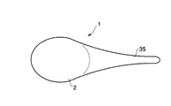
図10及び図11を参照して本発明の第6の実施形態に係るカプセル式内視鏡について説明する。本実施形態に係るカプセル式内視鏡1はそのカプセル本体2の後方部を柔らかい扁平な尾35として形成したものである。
【0042】
このような形状の尾35を持ったカプセル式内視鏡1によれば、カプセル本体2を飲み込み易いと共に、カプセル式内視鏡1を飲み込んだとき、尾35によってカプセル本体2の向きが安定し、確実に食道内を撮影することができる。また、カプセル本体2または尾35の部分をアンテナとしたり、その尾35の部分にアンテナを組み込んで構成したものであっても良い。例えば、カプセル本体2の外壁を利用してアンテナを構成してもよい。
【0043】
本発明は前述した各実施形態に限定されず、他の形態にも種々適用が可能である。上記実施形態では食道内の撮影に関して多くのものを説明したが、撮影の対象臓器は食道に限らず、食道以外の胃、十二指腸、小腸、大腸などの臓器内病変周辺等の関心領域検査用として撮影する場合にも適用ができる。この場合には位置検出手段の位置やタイマのプログラムを関心領域に合わせて設定すれば良い。
【0044】
また、上記実施形態で説明した各素子や回路等の電源になるバッテリをカプセル本体内に収納したカプセル式内視鏡に限定する必要はなく、例えば図6に示すように上記カプセル本体2内に電力受信器46を設け、カプセル本体2に向けて生体外からマイクロ波などの電波や光などの生体を透過する伝送手段により電力を上記カプセル本体2内に設けた電力受信器46に継続的に供給するタイプのカプセル式内視鏡でも当然良い。また、電力受信器46で受けた電力を蓄電する電池を設け、または上記バッテリ9に充電するようにしても良い。このような構成によれば、体内にあるカプセル式内視鏡に体外から非接触により電力を継続的に供給することができるので、体内のカプセル式内視鏡を長時間、確実に動作させることができるという効果を有する。具体的にはカプセル本体内に電力受信アンテナまたは太陽電池などの電力受信手段を内蔵し、体外の電力送信アンテナまたは発光板・発光部である発光手段を体内に向けて配置する構成となる。
【0045】
尚、本発明は前述した各実施形態に限定されるものではなく、他の形態にも適用が可能である。
【0046】
(付記)
前述した説明によれば、以下に列挙する事項および以下に列挙した事項のものを任意に組み合わせた事項が得られる。
【0047】
1.撮像素子、照明手段、バッテリ、画像信号処理回路、メモリ、画像情報伝送回路および無線送信用アンテナを、カプセル本体内に収納し、撮像素子で撮像した信号を画像信号処理回路によって処理して画像情報を生成し、この生成した画像情報を、一旦、メモリに蓄積し、メモリに蓄積した画像情報を、画像情報伝送回路により、体外に無線で送信するようにしたことを特徴とするカプセル式内視鏡。
1-1.1において、撮像素子による画像の撮影速度が、画像情報伝送回路による伝送速度に対して同一若しくは速いことを特徴とするカプセル式内視鏡。
1-2.1において、撮像素子による画像の撮影速度が、5フレーム/秒以上であることを特徴とするカプセル式内視鏡。
1-3.1において、撮像素子による画像の撮影速度が、プログラマブルであることを特徴とするカプセル式内視鏡。
1-4.1において、画像情報伝送回路による伝送速度が、プログラマブルであることを特徴とするカプセル式内視鏡。
【0048】
2.カプセル本体内に位置検出手段を収納し、位置検出手段によりカプセル本体の位置を検出するようにしたことを特徴とする請求項1に記載のカプセル式内視鏡。
2-1.2において、位置検出手段が、電磁界を検出するセンサであり、体外に設けた磁気コイルもしくは金属プレートに感応して位置を検出するようにしたことを特徴とするカプセル式内視鏡。
2-2.2において、位置検出手段によって検出される位置に応じて撮像素子による画像の撮像速度を変更もしくはオンーオフすることを特徴とするカプセル式内視鏡。
2-3.2において、位置検出手段によって検出される位置を体外に無線で送信するようにしたことを特徴とするカプセル式内視鏡。
2-4.2において、位置検出手段によって検出される位置をメモリに記憶するようにしたことを特徴とするカプセル式内視鏡。
2-5.2において、位置検出手段は、ジャイロ、加速度センサ、またはカプセル本体の移動速度を検出するセンサであることを特徴とするカプセル式内視鏡。
【0049】
3.撮像素子、照明手段、バッテリ、画像信号処理回路、メモリ、画像情報伝送回路、無線送信用アンテナおよびタイマを、カプセル本体内に収納し、タイマによってあらかじめ設定されたスケジュールに従い、撮像素子で撮像し、撮像した信号を画像信号処理回路によって処理して画像情報を生成し、生成した画像情報を、一旦、メモリに蓄積し、メモリに蓄積した画像情報を逐次、画像情報伝送回路により、体外に無線で送信するようにしたことを特徴とするカプセル式内視鏡。
【0050】
4.撮像素子を設置したカプセル本体の飲み込み方向の前端部とその反対側の後端部とが前後非対称の外形の構造体を形成することによってカプセル本体の進行方向に撮像部が向くように構成したことを特徴とする請求項1、請求項2または請求項3に記載のカプセル式内視鏡。
4-1.4において、カプセル本体の飲み込み方向の前端部の外径が、その反対側の後端部の径に対して小さいことを特徴とするカプセル式内視鏡。
【0051】
4-2.4において、カプセル本体の前後中央よりも飲み込み前方部位にカプセル本体の重心が位置することを特徴とするカプセル式内視鏡。
【0052】
5.カプセル本体の前後両端部に撮像部を有することを特徴とする請求項4に記載されたカプセル式内視鏡。
【0053】
6-1.体内を照明する手段と、体内を撮像する手段を有したカプセル内視鏡を口から飲み込み、カプセル内視鏡が食道を通る間に食道内を撮影する食道の撮影方法。
6-2.6-1において、食道を通る間に食道の全域を連続的に撮影する食道の撮影方法。
6-3.6-1において、5フレーム/秒以上の撮影速度で食道を撮影する6の撮影方法。
6-4.6-1において、カプセル内視鏡において撮影した画像をメモリに蓄積し、メモリから取り出した画像信号を、体外に無線で送信し、食道の観察を行う撮影方法。
【0054】
【発明の効果】
以上説明したように本発明によれば、カプセルが食道を通過する短い時間に多くのフレーム枚数の画像が撮影でき、検査の信頼性が増す。
【図面の簡単な説明】
【図1】本発明の第1の実施形態に係るカプセル式内視鏡を概略的に示す縦断面図。
【図2】同じく本発明の第1の実施形態に係るカプセル式内視鏡を概略的に示す横断面図。
【図3】同じく本発明の第1の実施形態においての体外に設置されるレシーバの概略図。
【図4】(a)は本発明の第1の実施形態に係るカプセル式内視鏡の使用説明図、(b)は(a)中b−b線に沿う部分の横断面図。
【図5】同じく本発明の第1の実施形態に係るカプセル式内視鏡の回路構成の説明図。
【図6】本発明の第2の実施形態に係るカプセル式内視鏡を概略的に示す縦断面図。
【図7】本発明の第3の実施形態に係るカプセル式内視鏡を概略的に示す縦断面図。
【図8】本発明の第4の実施形態に係るカプセル式内視鏡を概略的に示す縦断面図。
【図9】本発明の第5の実施形態に係るカプセル式内視鏡を概略的に示す縦断面図。
【図10】本発明の第6の実施形態に係るカプセル式内視鏡の側面図。
【図11】同じく本発明の第6の実施形態に係るカプセル式内視鏡の平面図。
【符号の説明】
1…カプセル式内視鏡
2…カプセル本体
3…基板
4…撮像素子
5…照明素子
6…画像信号処理回路
7…メモリ
8…画像信号伝送回路
9…バッテリ
10…アンテナ
11…位置検出手段
12…体外プレート
15…レシーバ
16…受信アンテナ
17…画像信号受信回路
18…画像記録手段
19…モニタ
20…患者
21…食道
31…タイマ
41…尾
W…重心[0001]
BACKGROUND OF THE INVENTION
The present invention relates to a capsule endoscope in which an imaging device is built in a capsule body and the inside of a body cavity is imaged by the imaging device.
[0002]
[Prior art and its problems]
Although it is highly reliable to insert an endoscope into the esophagus and directly observe and examine the presence or absence of lesions, this method requires a large facility. Not only that, but the burden on patients and surgeons was great. Therefore, endoscopy has been considered difficult to adopt as primary screening for mass screening.
[0003]
In general, primary screening for mass screening, etc., should be possible at least to diagnose the possibility of lesions, and it was important to have a simple test method that reduced costs and reduced patient pain and psychological anxiety. .
[0004]
Therefore, it has been desired to establish a simple examination means that can adopt a new method of directly observing the presence or absence of a lesion in the esophagus and accurately diagnosing it in the primary screening program.
[0005]
Therefore, an endoscope is configured in a capsule shape, and by swallowing the capsule, the inside of the esophagus is photographed while the capsule passes through the esophagus, and the image signal is transmitted to the outside of the body in real time by wireless or the like. Suggested a thing.
[0006]
However, video frames for transmitting images in real time are generally very slow, two frames per second. Nevertheless, the time for the capsule to pass through the esophagus is as short as 1 second. As a result, only one or two frames can be taken while the capsule passes through the esophagus. With this number of frames, the test results cannot be sufficiently trusted and are not suitable for diagnosis of the esophagus. In addition, there is a problem that the number of frames is too small to scrutinize even when photographing around a lesion in an organ other than the esophagus such as the stomach, duodenum, small intestine, large intestine, or region of interest.
[0007]
An object of the present invention is to provide a capsule endoscope that can capture a large number of frames in a short time during which the capsule passes through the esophagus, the periphery of a lesion in a body organ, or a region of interest.
[0008]
[Means for Solving the Problems]
The invention according to
The invention according to claim 2A memory for storing the image information is provided in the capsule body, and the image information stored in the memory is transmitted to the outside of the body.The capsule endoscope according to
The invention according to claim 3The imaging mode is determined by the imaging speed of the imaging device, the on / off operation of imaging, or the number of times of imaging.It is characterized
The invention according to claim 4The position detection device includes an electromagnetic wave detection sensor provided in the capsule body and an extracorporeal plate provided outside the body.The capsule endoscope according to
The invention according to claim 5The extracorporeal plate is a magnetic plate, a conductive plate, or a
The invention according to
Claim 7The invention according to7. The capsule-type inside according to
The invention according to
The invention according to
[0009]
DETAILED DESCRIPTION OF THE INVENTION
(First embodiment)
A capsule endoscope according to a first embodiment of the present invention will be described with reference to FIGS. 1 to 5.
[0010]
FIG. 1 schematically shows a
[0011]
As shown in FIG. 1, various built-in objects are incorporated in the storage chamber of the
[0012]
As the
[0013]
The image
[0014]
The position detecting means 11 includes a sensor for detecting the electromagnetic field at the location, and detects the position of the
[0015]
FIG. 3 shows the
[0016]
The
[0017]
Next, a method for using the
[0018]
Thereafter, the
[0019]
As shown in FIG. 4A, the
[0020]
As shown in FIGS. 4A and 4B, while detecting that the
[0021]
The time required for the
[0022]
30 (cm) / 6 (cm) / 1 (second) / = 5 (frame / second)
Of course, there are individual differences and observation depth variations in the conditions. For example, if the time for passing through the
[0023]
However, in the case of 5 frames / second or less, for example, 2 frames /Second placeIn this case, it is not easy to design the observation depth to be 10 cm or more, and it is not easy to observe a far point that is 10 cm or more away from a far point of a tubular organ such as the esophagus, so continuous observation is difficult. . Further, the time for passing through the
[0024]
The image
[0025]
After the
[0026]
The image signal picked up by the
[0027]
By the way, the transmission speed V2 by the image
[0028]
The image signals stored in the
[0029]
On the other hand, in the
[0030]
The position of the
[0031]
The position detection means 11 in the above embodiment detects the
[0032]
Further, the position detected by the position detection means 11 is stored in the
[0033]
(Second Embodiment)
A capsule endoscope according to a second embodiment of the present invention will be described with reference to FIG. In the
[0034]
Based on the time data of the
[0035]
(Third embodiment)
A capsule endoscope according to a third embodiment of the present invention will be described with reference to FIG. In the
[0036]
Thus, since the position of the center of gravity W of the
[0037]
(Fourth embodiment)
A capsule endoscope according to a fourth embodiment of the present invention will be described with reference to FIG. In the
[0038]
(Fifth embodiment)
A capsule endoscope according to a fifth embodiment of the present invention will be described with reference to FIG. The
[0039]
According to the
[0040]
Further, when the
[0041]
(Sixth embodiment)
A capsule endoscope according to a sixth embodiment of the present invention will be described with reference to FIGS. 10 and 11. In the
[0042]
According to the
[0043]
The present invention is not limited to the above-described embodiments, and can be variously applied to other forms. In the above embodiment, a lot of things have been described regarding imaging in the esophagus, but the target organ for imaging is not limited to the esophagus, but for examination of a region of interest such as the stomach, duodenum, small intestine, colon, etc. It can also be applied when shooting. In this case, the position detection means and the timer program may be set in accordance with the region of interest.
[0044]
Further, it is not necessary to limit the battery serving as a power source for each element or circuit described in the above embodiment to a capsule endoscope housed in the capsule body. For example, as shown in FIG. A power receiver 46 is provided, and power is continuously transmitted to the power receiver 46 provided in the capsule
[0045]
The present invention is not limited to the above-described embodiments, and can be applied to other forms.
[0046]
(Appendix)
According to the above description, items listed below and items obtained by arbitrarily combining the items listed below can be obtained.
[0047]
1. An image sensor, an illumination means, a battery, an image signal processing circuit, a memory, an image information transmission circuit, and a wireless transmission antenna are housed in the capsule body, and a signal captured by the image sensor is processed by the image signal processing circuit to obtain image information. The capsule-type endoscope is characterized in that the generated image information is temporarily stored in a memory, and the image information stored in the memory is wirelessly transmitted outside the body by an image information transmission circuit. mirror.
The capsule endoscope according to 1-1.1, wherein an image capturing speed of the image sensor is the same as or higher than a transmission speed of the image information transmission circuit.
The capsule endoscope according to 1-2.1, wherein an image capturing speed of the image sensor is 5 frames / second or more.
The capsule endoscope according to 1-3.1, wherein an image capturing speed of the image sensor is programmable.
The capsule endoscope according to 1-4.1, wherein a transmission speed of the image information transmission circuit is programmable.
[0048]
2. 2. The capsule endoscope according to
In 2.1.2, the position detection means is a sensor for detecting an electromagnetic field, and the position is detected in response to a magnetic coil or a metal plate provided outside the body. mirror.
The capsule endoscope according to 2.2.2, wherein the imaging speed of the image by the imaging device is changed or turned on / off according to the position detected by the position detecting means.
The capsule endoscope according to 2-3.2, wherein the position detected by the position detecting means is transmitted wirelessly outside the body.
The capsule endoscope according to 2-4, wherein the position detected by the position detecting means is stored in a memory.
2-5. The capsule endoscope according to 2-5, wherein the position detecting means is a gyroscope, an acceleration sensor, or a sensor that detects a moving speed of the capsule body.
[0049]
3. An image sensor, an illumination means, a battery, an image signal processing circuit, a memory, an image information transmission circuit, a wireless transmission antenna and a timer are housed in the capsule body, and imaged with the image sensor according to a schedule preset by the timer, The captured signal is processed by an image signal processing circuit to generate image information. The generated image information is temporarily stored in a memory, and the image information stored in the memory is sequentially transmitted to the outside of the body wirelessly by an image information transmission circuit. A capsule endoscope characterized by being transmitted.
[0050]
4). The capsule body with the image sensor installed is configured so that the front end in the swallowing direction and the rear end on the opposite side form a structure with an asymmetrical front-rear direction so that the imaging section faces the moving direction of the capsule body The capsule endoscope according to
The capsule endoscope according to 4-1.4, wherein the outer diameter of the front end portion of the capsule body in the swallowing direction is smaller than the diameter of the rear end portion on the opposite side.
[0051]
In 4-2.4, the capsule endoscope is characterized in that the center of gravity of the capsule body is located in a front part of swallowing from the front and rear center of the capsule body.
[0052]
5. 5. The capsule endoscope according to
[0053]
6-1. An esophageal imaging method in which a capsule endoscope having means for illuminating the body and means for imaging the body is swallowed from the mouth, and the inside of the esophagus is imaged while the capsule endoscope passes through the esophagus.
In 6-2.6-1, the esophageal imaging method in which the entire esophagus is continuously imaged while passing through the esophagus.
In 6-3.6-1, 6 shooting methods for shooting the esophagus at a shooting speed of 5 frames / second or more.
6. An imaging method in 6-6.6-1, in which an image taken with a capsule endoscope is stored in a memory, and an image signal taken out from the memory is wirelessly transmitted outside the body to observe the esophagus.
[0054]
【The invention's effect】
As described above, according to the present invention, a large number of frames can be taken in a short time during which the capsule passes through the esophagus, and the reliability of the inspection is increased.
[Brief description of the drawings]
FIG. 1 is a longitudinal sectional view schematically showing a capsule endoscope according to a first embodiment of the present invention.
FIG. 2 is a cross-sectional view schematically showing a capsule endoscope according to the first embodiment of the present invention.
FIG. 3 is a schematic view of a receiver installed outside the body in the first embodiment of the present invention.
4A is a diagram illustrating use of the capsule endoscope according to the first embodiment of the present invention, and FIG. 4B is a cross-sectional view of a portion along the line bb in FIG. 4A.
FIG. 5 is an explanatory diagram of a circuit configuration of the capsule endoscope according to the first embodiment of the present invention.
FIG. 6 is a longitudinal sectional view schematically showing a capsule endoscope according to a second embodiment of the present invention.
FIG. 7 is a longitudinal sectional view schematically showing a capsule endoscope according to a third embodiment of the present invention.
FIG. 8 is a longitudinal sectional view schematically showing a capsule endoscope according to a fourth embodiment of the present invention.
FIG. 9 is a longitudinal sectional view schematically showing a capsule endoscope according to a fifth embodiment of the present invention.
FIG. 10 is a side view of a capsule endoscope according to a sixth embodiment of the present invention.
FIG. 11 is a plan view of a capsule endoscope according to the sixth embodiment of the present invention.
[Explanation of symbols]
1 ... Capsule endoscope
2 ... Capsule body
3 ... Board
4 ... Image sensor
5 ... Lighting element
6 ... Image signal processing circuit
7 ... Memory
8. Image signal transmission circuit
9 ... Battery
10 ... Antenna
11: Position detecting means
12 ... External plate
15 ... Receiver
16 ... Receiving antenna
17 Image signal receiving circuit
18. Image recording means
19 ... Monitor
20 ... patient
21 ... Esophageal
31 ... Timer
41 ... tail
W ... Center of gravity
Claims (9)
前記カプセル本体の位置を検出する位置検出装置を設け、
検出された前記カプセル本体の位置情報に応じて、前記カプセル本体の撮影の形態を制御することを特徴とするカプセル式内視鏡。Imaging device, illumination means, the image signal processing circuits, the images information transmission circuit and the transmission antenna, provided in the capsule body, to generate image information signals obtained by the imaging device and processed by the image signal processing circuit , the image information, a capsule-type endoscope to be sent to outside by the image information transmission circuit and the transmitting antenna,
A position detection device for detecting the position of the capsule body is provided,
A capsule endoscope that controls a photographing mode of the capsule body in accordance with the detected position information of the capsule body .
Priority Applications (1)
| Application Number | Priority Date | Filing Date | Title |
|---|---|---|---|
| JP2002164786A JP4166509B2 (en) | 2001-06-20 | 2002-06-05 | Capsule endoscope |
Applications Claiming Priority (3)
| Application Number | Priority Date | Filing Date | Title |
|---|---|---|---|
| JP2001186827 | 2001-06-20 | ||
| JP2001-186827 | 2001-06-20 | ||
| JP2002164786A JP4166509B2 (en) | 2001-06-20 | 2002-06-05 | Capsule endoscope |
Related Child Applications (1)
| Application Number | Title | Priority Date | Filing Date |
|---|---|---|---|
| JP2005061562A Division JP4027944B2 (en) | 2001-06-20 | 2005-03-04 | Capsule endoscope |
Publications (3)
| Publication Number | Publication Date |
|---|---|
| JP2003070728A JP2003070728A (en) | 2003-03-11 |
| JP2003070728A5 JP2003070728A5 (en) | 2005-10-13 |
| JP4166509B2 true JP4166509B2 (en) | 2008-10-15 |
Family
ID=26617274
Family Applications (1)
| Application Number | Title | Priority Date | Filing Date |
|---|---|---|---|
| JP2002164786A Expired - Fee Related JP4166509B2 (en) | 2001-06-20 | 2002-06-05 | Capsule endoscope |
Country Status (1)
| Country | Link |
|---|---|
| JP (1) | JP4166509B2 (en) |
Families Citing this family (55)
| Publication number | Priority date | Publication date | Assignee | Title |
|---|---|---|---|---|
| KR100870033B1 (en) * | 2001-01-16 | 2008-11-21 | 기븐 이미징 리미티드 | System and method for wide field imaging of body lumens |
| US9113846B2 (en) | 2001-07-26 | 2015-08-25 | Given Imaging Ltd. | In-vivo imaging device providing data compression |
| IL155175A (en) | 2003-03-31 | 2012-01-31 | Given Imaging Ltd | Diagnostic device using data compression |
| CA2523288C (en) * | 2003-04-25 | 2009-06-23 | Olympus Corporation | Wireless in-vivo information acquiring system and body-insertable device |
| WO2004096023A1 (en) * | 2003-04-25 | 2004-11-11 | Olympus Corporation | Radio-type in-subject information acquisition system and outside-subject device |
| AU2007203429B2 (en) * | 2003-04-25 | 2009-06-11 | Olympus Corporation | Radio-type in-subject information acquisition system, device for introduction into subject, and outside-subject device |
| US7214182B2 (en) * | 2003-04-25 | 2007-05-08 | Olympus Corporation | Wireless in-vivo information acquiring system, body-insertable device, and external device |
| JP4562998B2 (en) * | 2003-05-20 | 2010-10-13 | オリンパス株式会社 | Capsule endoscope |
| JP4573502B2 (en) * | 2003-06-04 | 2010-11-04 | オリンパス株式会社 | Capsule endoscope and capsule endoscope apparatus |
| JP4526245B2 (en) * | 2003-07-04 | 2010-08-18 | オリンパス株式会社 | Video signal processing device |
| JP2005052637A (en) * | 2003-07-18 | 2005-03-03 | Pentax Corp | Capsule type device and capsule type device driving control system |
| JP4698938B2 (en) * | 2003-08-26 | 2011-06-08 | オリンパス株式会社 | Capsule endoscope and capsule endoscope system |
| JP2005074031A (en) * | 2003-09-01 | 2005-03-24 | Pentax Corp | Capsule endoscope |
| JP3993546B2 (en) * | 2003-09-08 | 2007-10-17 | オリンパス株式会社 | In-subject introduction apparatus and wireless in-subject information acquisition system |
| JP4656825B2 (en) * | 2003-09-08 | 2011-03-23 | オリンパス株式会社 | In-subject introduction apparatus and wireless in-subject information acquisition system |
| US7918786B2 (en) | 2003-11-11 | 2011-04-05 | Olympus Corporation | Capsule type medical device system, and capsule type medical device |
| JP4009581B2 (en) * | 2003-11-18 | 2007-11-14 | オリンパス株式会社 | Capsule medical system |
| WO2005053517A1 (en) * | 2003-12-01 | 2005-06-16 | Olympus Corporation | Endoscope system |
| WO2005060348A2 (en) * | 2003-12-24 | 2005-07-07 | Given Imaging Ltd. | Device, system and method for in-vivo imaging of a body lumen |
| JP2005192821A (en) * | 2004-01-07 | 2005-07-21 | Olympus Corp | Capsule type medical apparatus |
| JP4455067B2 (en) * | 2004-01-14 | 2010-04-21 | オリンパス株式会社 | Capsule endoscope device |
| JP3967731B2 (en) * | 2004-04-06 | 2007-08-29 | オリンパス株式会社 | Capsule endoscope |
| WO2005082226A1 (en) | 2004-02-27 | 2005-09-09 | Olympus Corporation | Endoscope |
| JP4231805B2 (en) * | 2004-02-27 | 2009-03-04 | オリンパス株式会社 | Capsule endoscope |
| JP4555604B2 (en) | 2004-05-10 | 2010-10-06 | オリンパス株式会社 | Capsule endoscope and capsule endoscope system |
| JP4573585B2 (en) * | 2004-07-06 | 2010-11-04 | オリンパス株式会社 | Intra-subject introduction apparatus and intra-subject introduction system |
| JP4578873B2 (en) * | 2004-07-08 | 2010-11-10 | オリンパス株式会社 | Intra-subject introduction apparatus and intra-subject introduction system |
| JP4598456B2 (en) * | 2004-08-06 | 2010-12-15 | オリンパス株式会社 | In-subject image acquisition system and in-subject introduction device |
| JP4554301B2 (en) * | 2004-08-30 | 2010-09-29 | オリンパス株式会社 | Position detection apparatus and in-subject introduction system |
| JP4505292B2 (en) * | 2004-09-13 | 2010-07-21 | オリンパス株式会社 | Intra-subject introduction system |
| US8050738B2 (en) | 2004-08-30 | 2011-11-01 | Olympus Corporation | Position detecting apparatus using the magnetic field direction of the earth's magnetic field |
| EP1792560B1 (en) * | 2004-08-30 | 2011-03-30 | Olympus Corporation | Position sensor |
| JP2006075533A (en) * | 2004-09-13 | 2006-03-23 | Olympus Corp | Intra-patient introduction system, receiver, and intra-patient introduction apparatus |
| EP1830691A2 (en) * | 2004-12-30 | 2007-09-12 | Given Imaging Ltd. | Device, system, and method for programmable in vivo imaging |
| JP4695432B2 (en) | 2005-04-12 | 2011-06-08 | オリンパスメディカルシステムズ株式会社 | In-subject introduction apparatus, in-subject information display apparatus, and in-subject information acquisition system |
| US7308292B2 (en) * | 2005-04-15 | 2007-12-11 | Sensors For Medicine And Science, Inc. | Optical-based sensing devices |
| JP4709579B2 (en) | 2005-04-26 | 2011-06-22 | オリンパスメディカルシステムズ株式会社 | Capsule endoscope |
| JP4855759B2 (en) | 2005-10-19 | 2012-01-18 | オリンパス株式会社 | Receiving apparatus and in-subject information acquisition system using the same |
| JP4855771B2 (en) | 2005-12-20 | 2012-01-18 | オリンパスメディカルシステムズ株式会社 | In-vivo image capturing apparatus and in-vivo image capturing system |
| KR20090009826A (en) * | 2006-03-30 | 2009-01-23 | 기븐 이미징 리미티드 | In-vivo sensing device and method for communicating between imagers and processor thereof |
| JP5019589B2 (en) * | 2007-03-28 | 2012-09-05 | 富士フイルム株式会社 | Capsule endoscope, capsule endoscope system, and method for operating capsule endoscope |
| JP5065812B2 (en) | 2007-08-29 | 2012-11-07 | オリンパスメディカルシステムズ株式会社 | In-vivo image acquisition device and in-vivo image acquisition system |
| JP4914790B2 (en) * | 2007-09-04 | 2012-04-11 | オリンパスメディカルシステムズ株式会社 | Intra-subject introduction device and method for producing intra-subject introduction device |
| KR100876673B1 (en) * | 2007-09-06 | 2009-01-07 | 아이쓰리시스템 주식회사 | Capsule-type endoscope capable of controlling frame rate of image |
| EP2072003B1 (en) | 2007-12-17 | 2016-08-10 | Olympus Corporation | Image display apparatus and image display system |
| JP2009226066A (en) | 2008-03-24 | 2009-10-08 | Olympus Corp | Capsule medical device |
| US8261751B2 (en) | 2008-07-08 | 2012-09-11 | Olympus Medical Systems Corp. | Guiding system, position controlling apparatus, and guiding method |
| CN102421350B (en) | 2009-03-11 | 2014-12-17 | 奥林巴斯医疗株式会社 | Image processing system, external device therefor, and image processing method therefor |
| CN102361585B (en) | 2009-03-23 | 2014-06-25 | 奥林巴斯医疗株式会社 | Image processing system, external apparatus and image processing method therefor |
| JP5355169B2 (en) * | 2009-03-24 | 2013-11-27 | オリンパス株式会社 | Capsule type medical device and capsule type medical system |
| EP2386239A4 (en) | 2009-05-12 | 2012-08-15 | Olympus Medical Systems Corp | Subject in-vivo imaging system and subject in-vivo introducing device |
| JP4700756B2 (en) * | 2010-04-19 | 2011-06-15 | オリンパス株式会社 | Capsule endoscope |
| JP5185991B2 (en) * | 2010-10-28 | 2013-04-17 | オリンパス株式会社 | Wireless in-subject information acquisition apparatus and wireless in-subject information acquisition system |
| JP5816469B2 (en) * | 2011-06-16 | 2015-11-18 | オリンパス株式会社 | Biological information acquisition system and method of operating biological information acquisition system |
| JP5480219B2 (en) * | 2011-09-22 | 2014-04-23 | オリンパス株式会社 | Receiving apparatus and in-subject information acquisition system using the same |
-
2002
- 2002-06-05 JP JP2002164786A patent/JP4166509B2/en not_active Expired - Fee Related
Also Published As
| Publication number | Publication date |
|---|---|
| JP2003070728A (en) | 2003-03-11 |
Similar Documents
| Publication | Publication Date | Title |
|---|---|---|
| JP4166509B2 (en) | Capsule endoscope | |
| JP4027944B2 (en) | Capsule endoscope | |
| US7704205B2 (en) | System and method of obtaining images of a subject using a capsule type medical device | |
| US8428685B2 (en) | System and method for magnetically maneuvering an in vivo device | |
| US7869856B2 (en) | Encapsulated medical imaging device and method | |
| JP4329394B2 (en) | Small photographing device | |
| JP2008521541A (en) | In vivo electrical stimulation devices, systems, and methods | |
| US20050043583A1 (en) | Endoscopy apparatus | |
| US8540623B2 (en) | Apparatus, system and method to indicate in-vivo device location | |
| JP2007082664A (en) | Capsule endoscope | |
| JP2005192632A (en) | Subject interior moving state detecting system | |
| WO2005023102A1 (en) | In-subject introducing device and wireless in-subject information capturing system | |
| US8206285B2 (en) | Apparatus, system and method to indicate in-vivo device location | |
| JP2006043276A (en) | System for obtaining intra-subject image and intra-subject introduction device | |
| JP4020834B2 (en) | Capsule type medical device and capsule type medical device communication system | |
| JP4383134B2 (en) | Wireless in-vivo information acquisition device | |
| JP4656824B2 (en) | Wireless in-vivo information acquisition device | |
| US20070142704A1 (en) | Image detection and storage device | |
| JP4590175B2 (en) | Wireless in-vivo information acquisition system | |
| JP2005278817A (en) | Position detecting system for inside of examinee's body | |
| ES2742101T3 (en) | Passive capsule endoscope for the intestine |
Legal Events
| Date | Code | Title | Description |
|---|---|---|---|
| A521 | Request for written amendment filed |
Free format text: JAPANESE INTERMEDIATE CODE: A523 Effective date: 20050601 |
|
| A621 | Written request for application examination |
Free format text: JAPANESE INTERMEDIATE CODE: A621 Effective date: 20050601 |
|
| A977 | Report on retrieval |
Free format text: JAPANESE INTERMEDIATE CODE: A971007 Effective date: 20071228 |
|
| TRDD | Decision of grant or rejection written | ||
| A01 | Written decision to grant a patent or to grant a registration (utility model) |
Free format text: JAPANESE INTERMEDIATE CODE: A01 Effective date: 20080722 |
|
| A01 | Written decision to grant a patent or to grant a registration (utility model) |
Free format text: JAPANESE INTERMEDIATE CODE: A01 |
|
| A61 | First payment of annual fees (during grant procedure) |
Free format text: JAPANESE INTERMEDIATE CODE: A61 Effective date: 20080730 |
|
| FPAY | Renewal fee payment (event date is renewal date of database) |
Free format text: PAYMENT UNTIL: 20110808 Year of fee payment: 3 |
|
| FPAY | Renewal fee payment (event date is renewal date of database) |
Free format text: PAYMENT UNTIL: 20120808 Year of fee payment: 4 |
|
| FPAY | Renewal fee payment (event date is renewal date of database) |
Free format text: PAYMENT UNTIL: 20130808 Year of fee payment: 5 |
|
| S531 | Written request for registration of change of domicile |
Free format text: JAPANESE INTERMEDIATE CODE: R313531 |
|
| R350 | Written notification of registration of transfer |
Free format text: JAPANESE INTERMEDIATE CODE: R350 |
|
| LAPS | Cancellation because of no payment of annual fees |